WO2024214733A1 - 照明装置 - Google Patents
照明装置 Download PDFInfo
- Publication number
- WO2024214733A1 WO2024214733A1 PCT/JP2024/014514 JP2024014514W WO2024214733A1 WO 2024214733 A1 WO2024214733 A1 WO 2024214733A1 JP 2024014514 W JP2024014514 W JP 2024014514W WO 2024214733 A1 WO2024214733 A1 WO 2024214733A1
- Authority
- WO
- WIPO (PCT)
- Prior art keywords
- light
- lens
- cup
- frame
- fresnel lens
- Prior art date
- Legal status (The legal status is an assumption and is not a legal conclusion. Google has not performed a legal analysis and makes no representation as to the accuracy of the status listed.)
- Ceased
Links
Images


Classifications
-
- F—MECHANICAL ENGINEERING; LIGHTING; HEATING; WEAPONS; BLASTING
- F21—LIGHTING
- F21S—NON-PORTABLE LIGHTING DEVICES; SYSTEMS THEREOF; VEHICLE LIGHTING DEVICES SPECIALLY ADAPTED FOR VEHICLE EXTERIORS
- F21S2/00—Systems of lighting devices, not provided for in main groups F21S4/00 - F21S10/00 or F21S19/00, e.g. of modular construction
-
- F—MECHANICAL ENGINEERING; LIGHTING; HEATING; WEAPONS; BLASTING
- F21—LIGHTING
- F21V—FUNCTIONAL FEATURES OR DETAILS OF LIGHTING DEVICES OR SYSTEMS THEREOF; STRUCTURAL COMBINATIONS OF LIGHTING DEVICES WITH OTHER ARTICLES, NOT OTHERWISE PROVIDED FOR
- F21V29/00—Protecting lighting devices from thermal damage; Cooling or heating arrangements specially adapted for lighting devices or systems
- F21V29/85—Protecting lighting devices from thermal damage; Cooling or heating arrangements specially adapted for lighting devices or systems characterised by the material
-
- G—PHYSICS
- G02—OPTICS
- G02B—OPTICAL ELEMENTS, SYSTEMS OR APPARATUS
- G02B6/00—Light guides; Structural details of arrangements comprising light guides and other optical elements, e.g. couplings
-
- F—MECHANICAL ENGINEERING; LIGHTING; HEATING; WEAPONS; BLASTING
- F21—LIGHTING
- F21Y—INDEXING SCHEME ASSOCIATED WITH SUBCLASSES F21K, F21L, F21S and F21V, RELATING TO THE FORM OR THE KIND OF THE LIGHT SOURCES OR OF THE COLOUR OF THE LIGHT EMITTED
- F21Y2115/00—Light-generating elements of semiconductor light sources
- F21Y2115/10—Light-emitting diodes [LED]
Definitions
- the present invention relates to a lighting device.
- Illumination devices such as spotlights are known that combine a cup lens and a Fresnel lens to improve light efficiency (see, for example, Patent Documents 1 and 2).
- Cup lenses and Fresnel lenses are naturally made from transparent, light-transmitting materials, but the surrounding materials are generally made from light-absorbing materials (black resin or materials with a black-colored surface) to prevent unnecessary light reflection within the frame that makes up the housing and to prevent light leakage from within the frame to the outside.
- light-absorbing materials black resin or materials with a black-colored surface
- the surroundings of light sources such as LEDs (Light Emitting Diodes) become hot due to heat generation, but in addition to that, light leaking from the cup lens can be absorbed by the surrounding materials, causing them to become hot, and this can exceed the heat resistance temperature of the materials made of resin, etc. If the heat resistance temperature is exceeded, the materials can become deformed, making it impossible to guarantee stable operation.
- LEDs Light Emitting Diodes
- the light-absorbing material Since one of the causes of the temperature rise is the light-absorbing material, it is possible to consider changing it to a material with other properties (light-transmitting material, light-diffusing and reflective material, etc.). However, since light-absorbing materials are originally designed to prevent unnecessary light reflection, there are concerns that changing it to this type of material could increase light leakage to the outside and result in a deterioration in the quality of the light (e.g. appearance).
- the present invention has been made in consideration of the above, and aims to provide a lighting device that can suppress temperature rise within the frame, reduce light leakage from within the frame to the outside, and maintain the quality of the light.
- an illumination device comprises a light source, a cup lens, a Fresnel lens, a light guide, and a specified structure.
- the light source is disposed on a base portion of a frame.
- the cup lens is disposed with its incident side facing the light source.
- the Fresnel lens is disposed on the exit side of the cup lens.
- the light guide has a substantially cylindrical wall portion surrounding the side of the cup lens, and a support portion extending inward from the wall portion and supporting a flange portion of the cup lens. The structure suppresses temperature rise within the frame and reduces light leakage from within the frame to the outside.
- the lighting device can suppress temperature rise within the frame, reduce light leakage from within the frame to the outside, and maintain the quality of the light.
- FIG. 1 is a cross-sectional view of a main part of a lighting device according to an embodiment.
- FIG. 2 is a perspective view of the ring-shaped sheet.
- FIG. 3 is a cross-sectional view showing another example of a main part of a lighting device.
- FIG. 1 is a cross-sectional view of the main parts of a lighting device 1 according to one embodiment.
- the lighting device 1 is substantially cylindrical, and its axial direction is the optical axis direction.
- the optical axis direction is the Z axis, but the position during use is arbitrary.
- the lighting device 1 has a roughly cylindrical frame 2 that also serves as a heat sink and constitutes a housing.
- the frame 2 has a roughly cylindrical wall portion 2a and a base portion 2b that extends inward from the wall portion 2a.
- a substrate 4 is disposed on the emission side (lower side in FIG. 1) of the base portion 2b via a heat dissipation sheet 3, and a light source 5 such as an LED (Light Emitting Diode) is disposed on the emission side (lower side in FIG. 1) of the substrate 4 with its light-emitting surface facing the emission side (lower side in FIG. 1).
- a substrate cover 6 is also provided on the base portion 2b via the heat dissipation sheet 3, and the substrate cover 6 is configured to sandwich the end of the substrate 4 between the base portion 2b.
- a cup lens 7 is arranged on the emission side of the light source 5, with its incident side facing the light source 5.
- the cup lens 7 has a body portion 7a that is approximately truncated cone shaped and an approximately annular flange portion 7b that is provided on the bottom side of the body portion 7a, where the area of the body portion 7a is larger.
- the side of the body portion 7a with the smaller area is the incident side, and the opposite side (lower side in Figure 1) is the emission side.
- the cup lens 7 also has an approximately cylindrical recess 7c provided on the incident side.
- the body portion 7a of the cup lens 7 may be approximately truncated pyramid shaped instead of approximately truncated cone shaped.
- the flange portion 7b is approximately rectangular frame shaped.
- a roughly cylindrical light guide 8 is disposed around the cup lens 7.
- the light guide 8 has a roughly cylindrical wall portion 8a that surrounds the side of the cup lens 7, and a support portion 8b that extends inward from the wall portion 8a and supports the flange portion 7b of the cup lens 7.
- a roughly annular cup lens holder 9 is provided at the tip of the support portion 8b of the light guide 8 to prevent the flange portion 7b of the cup lens 7 from coming off the support portion 8b of the light guide 8. Note that the cup lens holder 9 may not be provided in some cases.
- a roughly cylindrical Fresnel lens cylinder 10 is arranged around the light guide 8, and a roughly disk-shaped Fresnel lens 11 is arranged on the output side of the cup lens 7.
- the Fresnel lens 11 may be roughly rectangular instead of roughly disk-shaped.
- the Fresnel lens cylinder 10 has a wall 10a that is arranged between the wall 2a of the frame 2 and the wall 8a of the light guide 8, and a support 10b that extends inward from the wall 10a and supports the outer periphery of the Fresnel lens 11.
- a roughly cylindrical lens cylinder 13 is arranged inside the exit side (lower side in Figure 1) of the Fresnel lens cylinder 10.
- the lens cylinder 13 does not move in the optical axis direction (Z-axis direction) but can rotate around the optical axis.
- a spiral groove and a convex portion are provided on the outer surface of the lens cylinder 13 and the inner surface of the wall portion 10a of the Fresnel lens cylinder 10, and by rotating the lens cylinder 13, the Fresnel lens cylinder 10 can move in the optical axis direction. This causes the Fresnel lens 11 to approach or move away from the cup lens 7, making the light distribution variable.
- the cup lens 7 focuses the light emitted from the light source 5 within a wide angle range
- the Fresnel lens 11 focuses the light emitted from the cup lens 7 within a range from wide angle to narrow angle. Therefore, when the cup lens 7 and the Fresnel lens 11 are close to each other, the light distribution is wide-angle, and when they are far apart, the light distribution is narrow-angle.
- a ring-shaped sheet 12 is disposed on the cup lens 7 side of the outer periphery of the Fresnel lens 11.
- Figure 2 is a perspective view of the ring-shaped sheet 12.
- Fresnel lens cylinder 10 has been described as being approximately cylindrical, all or some of these may be, for example, approximately rectangular tubular, or generally speaking, approximately cylindrical.
- the Fresnel lens cylinder 10 is approximately rectangular tubular
- the Fresnel lens 11 will be approximately rectangular plate-like
- the ring-shaped sheet 12 in FIG. 2 will be a frame-shaped sheet with a rectangular corner frame shape.
- the ring-shaped sheet is an example of a frame-shaped sheet.
- the light guide 8 and cup lens holder 9 are formed from a transparent light-transmitting material, and a ring-shaped sheet 12 formed from a light-diffusing reflective material, a light-reflective material, or a light-absorbing material is arranged on the cup lens 7 side of the outer periphery of the Fresnel lens 11.
- a ring-shaped sheet 12 formed from a light-diffusing reflective material, a light-reflective material, or a light-absorbing material is arranged on the cup lens 7 side of the outer periphery of the Fresnel lens 11.
- at least the side of the Fresnel lens cylinder 10 and frame 2 that surround the transparent light guide 8 and cup lens holder 9 facing the cup lens 7 is formed from a light-absorbing material.
- Table 1 below shows the upper limit temperature and actual measured temperature of each part according to the light distribution state, the material or surface state of the light guide 8 and cup lens holder 9, and the presence or absence and material or surface state of the ring-shaped sheet 12.
- the light distribution is "wide angle” (the state in which the cup lens 7 and Fresnel lens 11 are close to each other), but the temperature of the ring-shaped sheet 12 is shown not only for the “wide angle” (shown as “wide”) but also for the "narrow angle” (shown as "narrow”).
- the materials or surface conditions of the light guide 8 and cup lens holder 9 are listed as follows: both are “black” (light absorbing material), both are “white” (light diffusive reflective material), and both are “transparent” (light transmissive material).
- the option is “none.” If the light guide 8 and cup lens holder 9 are "transparent,” the options are “black” (light-absorbing material) and “white” (light-diffusing, reflective material).
- “Environment” is the environment in which the lighting device 1 is placed, which is “35°C” in this case.
- the light guide 8 and cup lens holder 9 are "black.”
- the actual temperature of the light guide 8 is "101.1°C,” which exceeds the upper limit temperature of "85°C.”
- the actual temperature of the light guide 8 is "84.6°C,” which is below the upper limit temperature of "85°C.”
- the actual temperature of the lens cylinder 13 is "79.7°C,” which is below the upper limit temperature of "85°C.”
- the actual temperature of the ring-shaped sheet 12 is "85.0°C,” which is below the desired temperature of "90°C.”
- the actual temperature is "92.9°C,” which exceeds the desired temperature of "90°C.”
- the temperature of the ring-shaped sheet 12 rises at a narrow angle because, at a wide angle when the cup lens 7 and the Fresnel lens 11 are close to each other, the light from the cup lens 7 is concentrated in the center of the Fresnel lens 11 and does not hit the outer periphery, but when the cup lens 7 and the Fres
- the actual temperature of the light guide 8 is "84.9°C", which is below the upper limit temperature of "85°C”.
- the actual temperature of the lens cylinder 13 is "79.2°C", which is below the upper limit temperature of "85°C”.
- the actual temperature of the ring-shaped sheet 12 is "83.9°C", which is below the desired temperature of "90°C”. In the case of narrow angle, the actual temperature is "86.7°C", which is below the desired temperature of "90°C”. Therefore, this is more desirable than when the ring-shaped sheet 12 is "black”.
- the Fresnel lens cylinder 10 that surrounds the transparent light guide 8 and cup lens holder 9, and at least the side of the frame 2 that faces the cup lens 7 are made of a light-absorbing material, so that the leaked light can be effectively absorbed and problems prevented.
- Table 1 shows the cases where the ring-shaped sheet 12 is “black” and “white,” the effect of suppressing temperature rise is also observed when the ring-shaped sheet 12 is "gray” or is a "light-reflective material” such as a mirror-reflecting (aluminum-reflecting) surface.
- FIG. 3 is a cross-sectional view showing another example of the main parts of the lighting device 1, which is a second embodiment of the present invention.
- the biggest difference between the configuration of FIG. 3 and that of FIG. 1 is that a roughly cylindrical metal (e.g., aluminum) sleeve 14 is provided to surround the side of the cup lens 7.
- the other basic configuration is the same as that of FIG. 1, but the details are different.
- the Fresnel lens cylinder 10 that supports the Fresnel lens 11 engages with a roughly cylindrical drive cylinder 15 that surrounds the light guide 8 at a spiral groove and a convex portion, and the Fresnel lens cylinder 10 and the drive cylinder 15 rotate relatively to each other, allowing the Fresnel lens 11 to move in the optical axis direction (Z-axis direction).
- all or part of the frame 2, light guide 8, cup lens holder 9, and Fresnel lens cylinder 10 are not limited to being approximately cylindrical, but may be approximately cylindrical, in which case the sleeve 14 and drive cylinder 15 may also be approximately cylindrical.
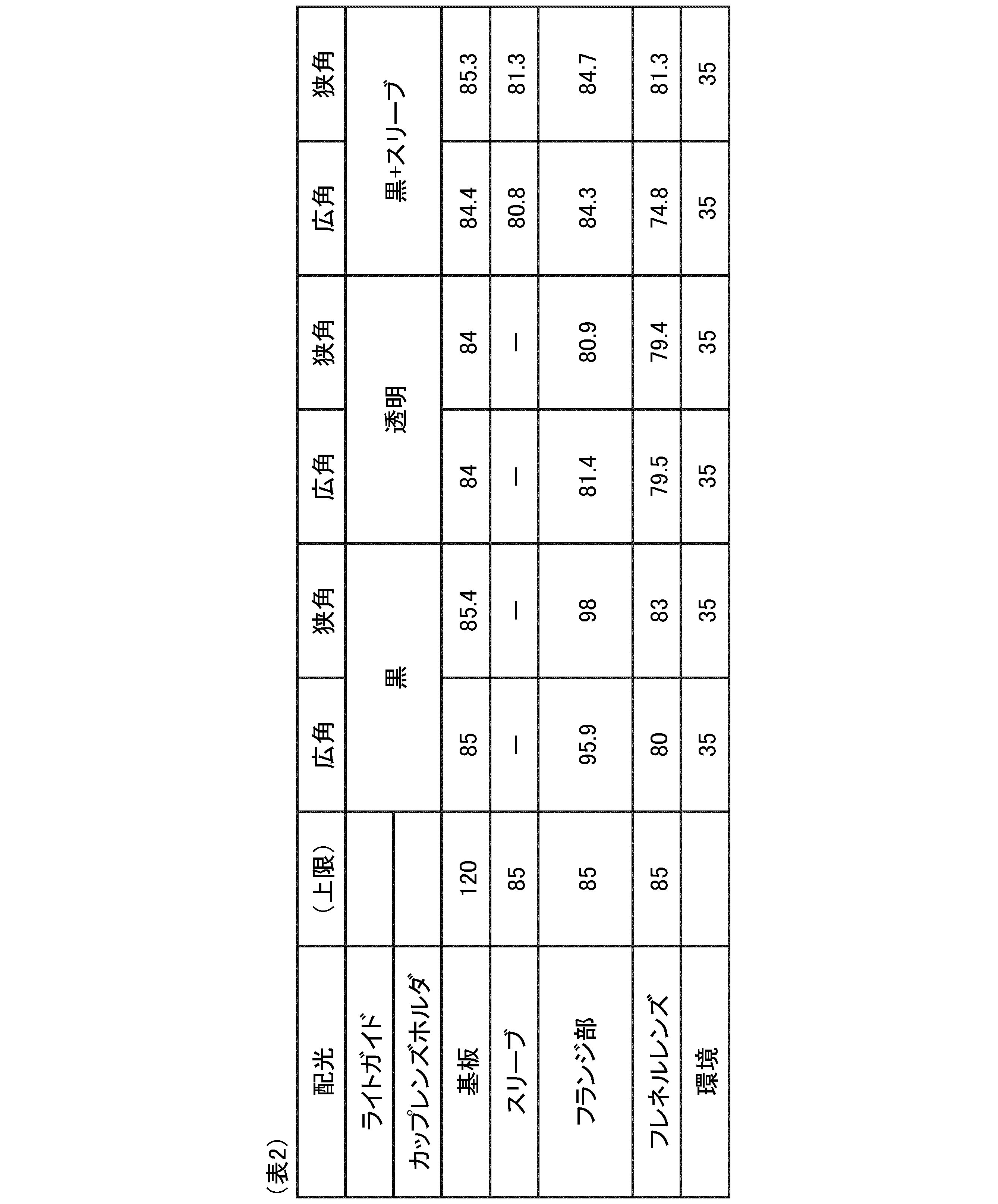
- Table 2 below shows the temperature of each part in relation to the state of light distribution and the material or surface state of the light guide 8 and cup lens holder 9. Note that when the light guide 8 and cup lens holder 9 are "black + sleeve", this indicates that the light guide 8 and cup lens holder 9 are “black” and also have a sleeve 14, while other light guides 8 and cup lens holders 9 that are "black” or “transparent” indicate that they do not have a sleeve 14.
- the flange portion 7b of the cup lens 7 is "84.3°C” for "wide angle” and “84.7°C” for “narrow angle”, both below the upper limit temperature of "85°C”.
- the sleeve 14 in this case is "80.8°C” for "wide angle” and “81.3°C” for “narrow angle”, both below the upper limit temperature of "85°C”. This is thought to be because the metal sleeve 14 disperses heat around the cup lens 7 and prevents the temperature from rising.
- the light guide 8 and cup lens holder 9 are made of a "black” light-absorbing material, unnecessary light reflection is suppressed, and it is possible to prevent glare on the exit side and light leakage behind the frame 2.
- a ring-shaped sheet (frame-shaped sheet) may be provided on the cup lens 7 side of the outer periphery of the Fresnel lens 11.
- the lighting device comprises a light source arranged on the base of a frame, a cup lens arranged with its incident side facing the light source, a Fresnel lens arranged on the exit side of the cup lens, a light guide having a substantially cylindrical wall portion surrounding the side of the cup lens and a support portion extending inward from the wall portion and supporting the flange portion of the cup lens, and a structure that suppresses temperature rise within the frame and reduces light leakage from within the frame to the outside. This makes it possible to suppress temperature rise within the frame and reduce light leakage from within the frame to the outside, thereby maintaining the quality of light.
- the structure includes the light guide formed of a light-transmitting material, a Fresnel lens cylinder having a substantially cylindrical wall portion surrounding the wall portion of the light guide and a support portion supporting the outer periphery of the Fresnel lens, and at least the side facing the cup lens is formed of a light-absorbing material, the frame having a side facing the cup lens formed of a light-absorbing material, and a light-diffusing and reflecting material or a frame-shaped sheet formed of a light-reflective material that is disposed on the cup lens side of the outer periphery of the Fresnel lens.
- the light guide transmits light, preventing heat generation in the light guide, and the light that transmits through the light guide is absorbed by the Fresnel lens cylinder, preventing unnecessary reflection.
- light that hits the outer periphery of the Fresnel lens when the light distribution angle is narrow is diffusely reflected by the ring-shaped sheet, preventing temperature rise in the outer periphery of the Fresnel lens.
- the structure also includes the light guide formed of a light-transmitting material, a Fresnel lens cylinder having a substantially cylindrical wall portion surrounding the wall portion of the light guide and a support portion supporting the outer periphery of the Fresnel lens, at least the side facing the cup lens being formed of a light-absorbing material, the frame having the side facing the cup lens being formed of a light-absorbing material, and a frame-shaped sheet formed of a light-absorbing material and disposed on the cup lens side of the outer periphery of the Fresnel lens.
- This makes it possible to specifically configure a structure that suppresses temperature rise within the frame and reduces light leakage from within the frame to the outside.
- the ring-shaped sheet formed of a light-absorbing material is less effective at suppressing temperature rise than a light-diffusing reflective material, but it does have the effect of suppressing the temperature below an upper limit temperature.
- the device also has a cup lens holder made of a light-transmitting material that covers the flange portion of the cup lens and the support portion of the light guide. This prevents the temperature of the cup lens holder from rising even when the cup lens holder is installed.
- the structure also has the light guide formed from a light-absorbing material, and a roughly cylindrical metal sleeve that surrounds the side of the cup lens. This makes it possible to specifically configure a structure that suppresses temperature rise within the frame and reduces light leakage from within the frame to the outside. In other words, the metal sleeve disperses heat around the cup lens, preventing temperature rise. Furthermore, because the light guide is formed from a light-absorbing material, unnecessary light reflection is suppressed.
- the Fresnel lens also has a frame-shaped sheet formed of a light diffusive reflecting material, a light reflecting material, or a light absorbing material, which is placed on the cup lens side of the outer periphery of the Fresnel lens. This prevents the temperature of the outer periphery of the Fresnel lens from rising.
- the cup lens also focuses the light emitted from the light source within a wide angle range, and the Fresnel lens focuses the light emitted from the cup lens within a range from wide angle to narrow angle. This makes it possible to cover a wide range of angles from wide angle to narrow angle.
- a Fresnel lens cylinder which has a roughly cylindrical wall portion surrounding the side of the Fresnel lens, and a support portion extending inward from the wall portion and supporting the outer periphery of the Fresnel lens, and the Fresnel lens cylinder is movable in the optical axis direction relative to the frame, and the light distribution from wide angle to narrow angle can be varied by the distance between the cup lens and the Fresnel lens in the optical axis direction. This makes it possible to vary the light distribution from wide angle to narrow angle.
- the cup lens has a body part that is shaped like a truncated cone or pyramid, and the flange part is shaped like a ring or a square frame and is provided on the bottom side where the area of the body part is larger.
- the side of the body part with the smaller area becomes the entrance side, and the Fresnel lens is shaped like a disk or a square plate. This makes it possible to configure a lighting device that is shaped like a cylinder.
- the present invention is not limited to the above-described embodiment.
- the present invention also includes configurations in which the above-described components are appropriately combined. Furthermore, further effects and modifications can be easily derived by those skilled in the art. Therefore, the broader aspects of the present invention are not limited to the above-described embodiment, and various modifications are possible.
Landscapes
- Physics & Mathematics (AREA)
- Engineering & Computer Science (AREA)
- General Engineering & Computer Science (AREA)
- General Physics & Mathematics (AREA)
- Optics & Photonics (AREA)
- Planar Illumination Modules (AREA)
Abstract
実施形態の照明装置(1)は、光源(5)と、カップレンズ(7)と、フレネルレンズ(11)と、ライトガイド(8)と、所定の構造とを備える。前記光源(5)は、フレーム(2)の基台部(2b)に配置される。前記カップレンズ(7)は、前記光源(5)に入射側を向けて配置される。前記フレネルレンズ(11)は、前記カップレンズ(7)の出射側に配置される。前記ライトガイド(8)は、前記カップレンズ(7)の側面側を包囲する略筒状の壁部(2a)と、該壁部(2a)から内側に延在し前記カップレンズ(7)のフランジ部(7b)を支持する支持部(8b)とを有する。前記構造は、前記フレーム(2)内の温度上昇を抑えるとともに、前記フレーム(2)内から外部への漏れ光を低減する。
Description
本発明は、照明装置に関する。
スポットライト等の照明装置として、光効率向上のためにカップレンズとフレネルレンズとを組み合わせたものが知られている(例えば、特許文献1、2等を参照)。
カップレンズやフレネルレンズは当然ながら透明な光透過性部材により形成されるが、その周囲の部材は、筐体を構成するフレーム内での不要な光の反射を防ぎ、フレーム内から外部への光漏れを防ぐために、一般に光吸収性部材(黒色の樹脂や、表面が黒色に着色された部材)で構成されている。
ところで、LED(Light Emitting Diode)等の光源の周囲は発熱により高温となるが、それ以外にも、カップレンズから漏れる光によりその周囲の部材に光が吸収されて高温になり、樹脂等により形成される部材の耐熱温度を超えてしまう場合がある。耐熱温度を超えてしまうことで、部材の変形等が生じ、安定した動作を保証できなくなる。
温度上昇の原因の一つが光吸収性部材であることから、それを他の性質の部材(光透過性部材、光拡散反射性部材等)に変えることも考えられるが、そもそも光吸収性部材は不要な光の反射を防ぐためのものであることから、その変更により外部への漏れ光の増加やそれによる光の質(例えば見栄え)の悪化が懸念される。
本発明は、上記に鑑みてなされたものであって、フレーム内の温度上昇を抑えるとともに、フレーム内から外部への漏れ光を低減し光の質を維持することのできる照明装置を提供することを目的とする。
上述した課題を解決し、目的を達成するために、本発明の一態様に係る照明装置は、光源と、カップレンズと、フレネルレンズと、ライトガイドと、所定の構造とを備える。前記光源は、フレームの基台部に配置される。前記カップレンズは、前記光源に入射側を向けて配置される。前記フレネルレンズは、前記カップレンズの出射側に配置される。前記ライトガイドは、前記カップレンズの側面側を包囲する略筒状の壁部と、該壁部から内側に延在し前記カップレンズのフランジ部を支持する支持部とを有する。前記構造は、前記フレーム内の温度上昇を抑えるとともに、前記フレーム内から外部への漏れ光を低減する。
本発明の一態様に係る照明装置は、フレーム内の温度上昇を抑えるとともに、フレーム内から外部への漏れ光を低減し光の質を維持することができる。
以下、実施形態に係る照明装置について図面を参照して説明する。なお、この実施形態によりこの発明が限定されるものではない。また、図面における各要素の寸法の関係、各要素の比率などは、現実と異なる場合がある。図面の相互間においても、互いの寸法の関係や比率が異なる部分が含まれている場合がある。また、1つの実施形態や変形例に記載された内容は、原則として他の実施形態や変形例にも同様に適用される。
図1は、一実施形態にかかる照明装置1の要部の断面図である。図1において、照明装置1は略円柱状であり、その軸方向が光軸方向となっている。図では光軸方向がZ軸とされているが、使用時における姿勢は任意である。
照明装置1は、ヒートシンクを兼ね、筐体を構成する略円筒状のフレーム2を有している。フレーム2は、略円筒状の壁部2aと、壁部2aから内側に延在する基台部2bとを有している。基台部2bの出射側(図1における下側)には、放熱シート3を介して基板4が配置され、基板4の出射側(図1における下側)にはLED(Light Emitting Diode)等の光源5が出射側(図1における下側)に発光面を向けて配置されている。基台部2bには、放熱シート3を介して基板カバー6も設けられ、基板カバー6は基板4の端部を基台部2bとの間で挟み込むようになっている。
光源5の出射側には、光源5に入射側を向けてカップレンズ7が配置されている。カップレンズ7は、略円錐台の形状の本体部7aと、この本体部7aの面積が大きい底面側に設けられる略円環状のフランジ部7bとを有し、本体部7aの面積が小さい側(図1の上側)が入射側となり、反対側(図1の下側)が出射側となっている。また、カップレンズ7は、入射側に設けられた略円柱状の凹部7cを有している。なお、カップレンズ7の本体部7aは略円錐台の形状に代えて略角錐台の形状としてもよい。この場合、フランジ部7bは略角枠状となる。
カップレンズ7の周囲には、略円筒状のライトガイド8が配置されている。ライトガイド8は、カップレンズ7の側面側を包囲する略円筒状の壁部8aと、この壁部8aから内側に延在しカップレンズ7のフランジ部7bを支持する支持部8bとを有している。
ライトガイド8の支持部8bの先端には、カップレンズ7のフランジ部7bがライトガイド8の支持部8bから外れないようにするための、略円環状のカップレンズホルダ9が設けられている。なお、カップレンズホルダ9は設けられない場合もある。
ライトガイド8の周囲には、略円筒状のフレネルレンズシリンダ10が配置されており、カップレンズ7の出射側には略円板状のフレネルレンズ11が配置されている。フレネルレンズ11は略円板状に代えて略角板状としてもよい。フレネルレンズシリンダ10は、フレーム2の壁部2aとライトガイド8の壁部8aとの間に配置される壁部10aと、この壁部10aから内側に延在しフレネルレンズ11の外周部を支持する支持部10bとを有している。
フレネルレンズシリンダ10の出射側(図1の下側)の内側には略円筒状のレンズシリンダ13が配置されている。レンズシリンダ13は光軸方向(Z軸方向)に対しては移動せず、光軸を中心に回転が可能になっている。レンズシリンダ13の外面とフレネルレンズシリンダ10の壁部10aの内面とには、例えば螺旋状の溝と凸部とが設けられ、レンズシリンダ13が回転することにより、フレネルレンズシリンダ10は光軸方向に移動が可能である。これにより、フレネルレンズ11がカップレンズ7に対して接近・離間することとなり、配光が可変となる。
カップレンズ7は、光源5から出た光を広角の範囲内で集光し、フレネルレンズ11は、カップレンズ7から出た光を広角から狭角の範囲内で集光する。従って、カップレンズ7とフレネルレンズ11とが近づいた状態では広角の配光となり、離れた状態では狭角の配光となる。
また、フレネルレンズ11の外周部のカップレンズ7側には、リング状シート12が配置されている。図2は、リング状シート12の斜視図である。
なお、フレーム2やライトガイド8やカップレンズホルダ9やフレネルレンズシリンダ10やレンズシリンダ13が略円筒状である場合について説明したが、これらの全てまたは一部は例えば略角筒状でもよく、一般化すれば略筒状であればよい。フレネルレンズシリンダ10が略角筒状となる場合、フレネルレンズ11は略角板状となり、図2のリング状シート12は、矩形状の角枠状の枠状シートとなる。リング状シートは枠状シートの一例である。
本発明の第1の実施形態では、ライトガイド8およびカップレンズホルダ9が透明な光透過性部材により形成されるとともに、光拡散反射性部材、光反射性部材または光吸収性部材により形成されたリング状シート12がフレネルレンズ11の外周部のカップレンズ7側に配置されるものとしている。また、透明なライトガイド8およびカップレンズホルダ9を包囲するフレネルレンズシリンダ10およびフレーム2の少なくともカップレンズ7に対向する側が光吸収性部材により形成されている。
以下の表1は、配光の状態と、ライトガイド8およびカップレンズホルダ9の材質または表面の状態、リング状シート12の有無および材質または表面の状態に対し、各部の上限温度と実測による温度とを示している。配光は原則として「広角」(カップレンズ7とフレネルレンズ11とが近づいた状態)としているが、リング状シート12の温度については「広角」(「広」と表示)以外に「狭角」(「狭」と表示)の場合についても示している。
ライトガイド8およびカップレンズホルダ9の材質または表面の状態としては、両者とも「黒」(光吸収性部材)の場合と、両者とも「白」(光拡散反射性部材)の場合と、両者とも「透明」(光透過性部材)の場合とが挙げられている。
リング状シート12については、ライトガイド8およびカップレンズホルダ9が「黒」または「白」の場合は「なし」で、ライトガイド8およびカップレンズホルダ9が「透明」の場合は、「黒」(光吸収性部材)の場合と、「白」(光拡散反射性部材)の場合とが挙げられている。
「環境」は照明装置1が置かれた環境であり、ここでは「35°C」となっている。

表1においてライトガイド8およびカップレンズホルダ9が「黒」の場合である。この場合、ライトガイド8が実測で「101.1°C」であり、上限温度「85°C」を超えている。
表1において、ライトガイド8およびカップレンズホルダ9が「白」の場合でも、ライトガイド8が実測で「90.0°C」であり、上限温度「85°C」を超えている。このことから、ライトガイド8およびカップレンズホルダ9を「白」にしても温度上昇は防げないことがわかる。また、表1からはわからないが、ライトガイド8およびカップレンズホルダ9が「白」の場合は、ライトガイド8およびカップレンズホルダ9の表面から光が拡散反射し、光漏れによる弊害も発生する。
一方、ライトガイド8およびカップレンズホルダ9が「透明」で、リング状シート12が「黒」の場合、ライトガイド8が実測で「84.6°C」であり、上限温度「85°C」を下回っている。また、レンズシリンダ13は実測で「79.7°C」であり、上限温度「85°C」を下回っている。リング状シート12は実測で「85.0°C」であり、希望温度「90°C」を下回っている。しかし、狭角の場合については、実測で「92.9°C」であり、希望温度「90°C」を超えている。狭角の際にリング状シート12(フレネルレンズ11の外周部)の温度が上昇するのは、カップレンズ7とフレネルレンズ11とが近づいている広角の際にはカップレンズ7の光がフレネルレンズ11の中央に集まり外周部には当たらなかったのが、カップレンズ7とフレネルレンズ11とが離れることでカップレンズ7の光がフレネルレンズ11の外周部にも当たることによる。
ライトガイド8およびカップレンズホルダ9が「透明」で、リング状シート12が「白」の場合、ライトガイド8が実測で「84.9°C」であり、上限温度「85°C」を下回っている。また、レンズシリンダ13は実測で「79.2°C」であり、上限温度「85°C」を下回っている。リング状シート12は実測で「83.9°C」であり、希望温度「90°C」を下回っている。また、狭角の場合についても、実測で「86.7°C」であり、希望温度「90°C」を下回っている。よって、リング状シート12が「黒」の場合よりも望ましい。
なお、表1からはわからないが、ライトガイド8およびカップレンズホルダ9が「透明」となることで、ライトガイド8およびカップレンズホルダ9を透過した光が漏れ光となって、出射側に出ることでグレア感が出てしまったり、フレーム2の背後から漏れてしまったりする弊害が考えられる。しかし、前述のように第1の実施形態では、透明なライトガイド8およびカップレンズホルダ9を包囲するフレネルレンズシリンダ10およびフレーム2の少なくともカップレンズ7に対向する側が光吸収性部材により形成されているため、漏れ光を有効に吸収し、弊害を防止することができる。
なお、表1ではリング状シート12が「黒」の場合と「白」の場合とについて示されているが、リング状シート12が「グレー」の場合や、鏡面反射(アルミ反射)のような「光反射性部材」の場合であっても、温度上昇を抑える効果がある。
図3は、照明装置1の要部の他の例を示す断面図であり、本発明の第2の実施形態である。図3においては、図1の構成と比較して最も異なる点は、カップレンズ7の側面側を包囲する略円筒状の金属製(例えば、アルミニウム製)のスリーブ14が設けられた点である。また、その他の基本的な構成は図1と同様であるが、細部は異なっている。例えば、フレネルレンズ11を支持するフレネルレンズシリンダ10は、ライトガイド8を包囲する略円筒状の駆動シリンダ15と螺旋状の溝と凸部とで噛み合っており、フレネルレンズシリンダ10と駆動シリンダ15とが相対的に回転することで、フレネルレンズ11は光軸方向(Z軸方向)に移動可能になっている。
また、第1の実施形態と同様に、フレーム2やライトガイド8やカップレンズホルダ9やフレネルレンズシリンダ10の全部または一部は略円筒状に限らず略筒状であればよく、その場合、スリーブ14や駆動シリンダ15も略筒状となってもよい。
以下の表2は、配光の状態と、ライトガイド8およびカップレンズホルダ9の材質または表面の状態に対し、各部の温度を示している。なお、ライトガイド8およびカップレンズホルダ9が「黒+スリーブ」とあるのは、ライトガイド8およびカップレンズホルダ9が「黒」で、更にスリーブ14がある場合を示しており、その他のライトガイド8およびカップレンズホルダ9が「黒」または「透明」は、スリーブ14がない場合を示している。
表2において、ライトガイド8およびカップレンズホルダ9が「黒」でスリーブ14がない場合、カップレンズ7のフランジ部7bは、「広角」の場合は「95.9°C」、「狭角」の場合は「98°C」であり、上限温度「85°C」を超えている。また、ライトガイド8およびカップレンズホルダ9が「透明」でスリーブ14がない場合、カップレンズ7のフランジ部7bは、「広角」の場合は「81.4°C」、「狭角」の場合は「80.9°C」であり、上限温度「85°C」を下回っている。しかし、表2からは分からないが、ライトガイド8およびカップレンズホルダ9が「透明」となることで、ライトガイド8およびカップレンズホルダ9を透過した光が漏れ光となって、出射側に出ることでグレア感が出てしまったり、フレーム2の背後から漏れてしまったりする不都合が発生する。
この点、ライトガイド8およびカップレンズホルダ9が「黒」でスリーブ14がある場合、カップレンズ7のフランジ部7bは、「広角」の場合は「84.3°C」、「狭角」の場合は「84.7°C」であり、上限温度「85°C」を下回っている。なお、この際のスリーブ14は「広角」の場合は「80.8°C」、「狭角」の場合は「81.3°C」であり、上限温度「85°C」を下回っている。これは、金属製のスリーブ14によりカップレンズ7の周辺の熱が分散され、温度上昇が防止されるものと考えられる。また、ライトガイド8およびカップレンズホルダ9は「黒」の光吸収性部材により形成されているため、不要な光の反射が抑制され、出射側でのグレア感やフレーム2背後の漏れ光を防止することができる。
なお、第2の実施形態を示す図3では、第1の実施形態(図1、図2)におけるリング状シート12に相当するものは示されていないが、第1の実施形態と同様に、リング状シート(枠状シート)がフレネルレンズ11の外周部のカップレンズ7側に設けられるようにしてもよい。
以上、本発明の実施形態について説明したが、本発明は上記実施形態に限定されるものではなく、その趣旨を逸脱しない限りにおいて種々の変更が可能である。
以上のように、実施形態に係る照明装置は、フレームの基台部に配置された光源と、前記光源に入射側を向けて配置されたカップレンズと、前記カップレンズの出射側に配置されたフレネルレンズと、前記カップレンズの側面側を包囲する略筒状の壁部と、該壁部から内側に延在し前記カップレンズのフランジ部を支持する支持部とを有するライトガイドと、前記フレーム内の温度上昇を抑えるとともに、前記フレーム内から外部への漏れ光を低減する構造と、を備える。これにより、フレーム内の温度上昇を抑えるとともに、フレーム内から外部への漏れ光を低減し光の質を維持することができる。
また、前記構造は、光透過性部材により形成された前記ライトガイドと、前記ライトガイドの壁部を包囲する略筒状の壁部を有し、前記フレネルレンズの外周部を支持する支持部を有し、少なくとも前記カップレンズに対向する側が光吸収性部材により形成されたフレネルレンズシリンダと、前記カップレンズに対向する側が光吸収性部材により形成された前記フレームと、前記フレネルレンズの外周部の前記カップレンズ側に配置される光拡散反射性部材あるいは光反射性部材により形成された枠状シートと、を有する。これにより、フレーム内の温度上昇を抑えるとともに、フレーム内から外部への漏れ光を低減する構造を具体的に構成することができる。すなわち、ライトガイドが光を透過することによりライトガイドでの発熱が防止され、ライトガイドを透過した光はフレネルレンズシリンダで吸収されるため不要な反射が防止される。また、特に狭角の配光時にフレネルレンズの外周部に当たる光はリング状シートにより拡散反射され、フレネルレンズの外周部の温度上昇が防止される。
また、前記構造は、光透過性部材により形成された前記ライトガイドと、前記ライトガイドの壁部を包囲する略筒状の壁部を有し、前記フレネルレンズの外周部を支持する支持部を有し、少なくとも前記カップレンズに対向する側が光吸収性部材により形成されたフレネルレンズシリンダと、前記カップレンズに対向する側が光吸収性部材により形成された前記フレームと、前記フレネルレンズの外周部の前記カップレンズ側に配置される光吸収性部材により形成された枠状シートと、を有する。これにより、フレーム内の温度上昇を抑えるとともに、フレーム内から外部への漏れ光を低減する構造を具体的に構成することができる。光吸収性部材により形成されたリング状シートは、光拡散反射性部材による場合よりは温度上昇を抑える効果は劣るが、上限温度以下に抑える効果はある。
また、前記カップレンズのフランジ部と前記ライトガイドの支持部とを覆う、光透過性部材により形成されたカップレンズホルダを有する。これにより、カップレンズホルダが設けられる場合にも、カップレンズホルダの温度上昇が防止される。
また、前記構造は、光吸収性部材により形成された前記ライトガイドと、前記カップレンズの側面側を包囲する略筒状の金属製のスリーブと、を有する。これにより、フレーム内の温度上昇を抑えるとともに、フレーム内から外部への漏れ光を低減する構造を具体的に構成することができる。すなわち、金属製のスリーブによりカップレンズの周辺の熱が分散され、温度上昇が防止される。また、ライトガイドは光吸収性部材により形成されているため、不要な光の反射が抑制される。
また、前記フレネルレンズの外周部の前記カップレンズ側に配置される光拡散反射性部材、光反射性部材あるいは光吸収性部材により形成された枠状シートを有する。これにより、フレネルレンズの外周部の温度上昇が防止される。
また、前記カップレンズは、前記光源から出た光を広角の範囲内で集光し、前記フレネルレンズは、前記カップレンズから出た光を広角から狭角の範囲内で集光する。これにより、広角から狭角までをカバーすることができる。
また、前記フレネルレンズの側面側を包囲する略筒状の壁部と、該壁部から内側に延在し前記フレネルレンズの外周部を支持する支持部を有するフレネルレンズシリンダを備え、前記フレネルレンズシリンダは前記フレームに対して光軸方向に移動可能とされ、前記カップレンズと前記フレネルレンズの光軸方向の距離により広角から狭角までの配光が可変とされる。これにより、広角から狭角までの配光を可変とすることができる。
また、前記カップレンズは、略円錐台または略角錐台の形状の本体部と、前記本体部の面積が大きい底面側に設けられる略円環状または略角枠状の前記フランジ部とを有し、前記本体部の面積が小さい側が前記入射側となり、前記フレネルレンズは、略円板状または略角板状である。これにより、略円筒状の照明装置を構成することができる。
また、上記実施の形態により本発明が限定されるものではない。上述した各構成要素を適宜組み合わせて構成したものも本発明に含まれる。また、さらなる効果や変形例は、当業者によって容易に導き出すことができる。よって、本発明のより広範な態様は、上記の実施の形態に限定されるものではなく、様々な変更が可能である。
1 照明装置,2 フレーム,2a 壁部,2b 基台部,3 放熱シート,4 基板,5 光源,6 基板カバー,7 カップレンズ,7a 本体部,7b フランジ部,7c 凹部,8 ライトガイド,8a 壁部,8b 支持部,9 カップレンズホルダ,10 フレネルレンズシリンダ,10a 壁部,10b 支持部,11 フレネルレンズ,12 リング状シート,13 レンズシリンダ,14 スリーブ,15 駆動シリンダ
Claims (9)
- フレームの基台部に配置された光源と、
前記光源に入射側を向けて配置されたカップレンズと、
前記カップレンズの出射側に配置されたフレネルレンズと、
前記カップレンズの側面側を包囲する略筒状の壁部と、該壁部から内側に延在し前記カップレンズのフランジ部を支持する支持部とを有するライトガイドと、
前記フレーム内の温度上昇を抑えるとともに、前記フレーム内から外部への漏れ光を低減する構造と、
を備える照明装置。 - 前記構造は、
光透過性部材により形成された前記ライトガイドと、
前記ライトガイドの壁部を包囲する略筒状の壁部を有し、前記フレネルレンズの外周部を支持する支持部を有し、少なくとも前記カップレンズに対向する側が光吸収性部材により形成されたフレネルレンズシリンダと、
前記カップレンズに対向する側が光吸収性部材により形成された前記フレームと、
前記フレネルレンズの外周部の前記カップレンズ側に配置される光拡散反射性部材あるいは光反射性部材により形成された枠状シートと、を有する、
請求項1に記載の照明装置。 - 前記構造は、
光透過性部材により形成された前記ライトガイドと、
前記ライトガイドの壁部を包囲する略筒状の壁部を有し、前記フレネルレンズの外周部を支持する支持部を有し、少なくとも前記カップレンズに対向する側が光吸収性部材により形成されたフレネルレンズシリンダと、
前記カップレンズに対向する側が光吸収性部材により形成された前記フレームと、
前記フレネルレンズの外周部の前記カップレンズ側に配置される光吸収性部材により形成された枠状シートと、を有する、
請求項1に記載の照明装置。 - 前記カップレンズのフランジ部と前記ライトガイドの支持部とを覆う、光透過性部材により形成されたカップレンズホルダを有する、
請求項2または3に記載の照明装置。 - 前記構造は、光吸収性部材により形成された前記ライトガイドと、前記カップレンズの側面側を包囲する略筒状の金属製のスリーブと、を有する、
請求項1に記載の照明装置。 - 前記フレネルレンズの外周部の前記カップレンズ側に配置される光拡散反射性部材、光反射性部材あるいは光吸収性部材により形成された枠状シートを有する、
請求項5に記載の照明装置。 - 前記カップレンズは、前記光源から出た光を広角の範囲内で集光し、
前記フレネルレンズは、前記カップレンズから出た光を広角から狭角の範囲内で集光する、
請求項1に記載の照明装置。 - 前記フレネルレンズの側面側を包囲する略筒状の壁部と、該壁部から内側に延在し前記フレネルレンズの外周部を支持する支持部を有するフレネルレンズシリンダを備え、
前記フレネルレンズシリンダは前記フレームに対して光軸方向に移動可能とされ、前記カップレンズと前記フレネルレンズの光軸方向の距離により広角から狭角までの配光が可変とされる、
請求項1に記載の照明装置。 - 前記カップレンズは、略円錐台または略角錐台の形状の本体部と、前記本体部の面積が大きい底面側に設けられる略円環状または略角枠状の前記フランジ部とを有し、前記本体部の面積が小さい側が前記入射側となり、
前記フレネルレンズは、略円板状または略角板状である、
請求項1に記載の照明装置。
Applications Claiming Priority (2)
| Application Number | Priority Date | Filing Date | Title |
|---|---|---|---|
| JP2023064834A JP7642702B2 (ja) | 2023-04-12 | 2023-04-12 | 照明装置 |
| JP2023-064834 | 2023-04-12 |
Publications (1)
| Publication Number | Publication Date |
|---|---|
| WO2024214733A1 true WO2024214733A1 (ja) | 2024-10-17 |
Family
ID=93059441
Family Applications (1)
| Application Number | Title | Priority Date | Filing Date |
|---|---|---|---|
| PCT/JP2024/014514 Ceased WO2024214733A1 (ja) | 2023-04-12 | 2024-04-10 | 照明装置 |
Country Status (2)
| Country | Link |
|---|---|
| JP (1) | JP7642702B2 (ja) |
| WO (1) | WO2024214733A1 (ja) |
Citations (3)
| Publication number | Priority date | Publication date | Assignee | Title |
|---|---|---|---|---|
| JP2015088389A (ja) * | 2013-10-31 | 2015-05-07 | パナソニックIpマネジメント株式会社 | 照明装置 |
| JP2017208206A (ja) * | 2016-05-17 | 2017-11-24 | パナソニックIpマネジメント株式会社 | 照明装置 |
| JP2021072280A (ja) * | 2019-10-30 | 2021-05-06 | 日亜化学工業株式会社 | 光源装置 |
Family Cites Families (1)
| Publication number | Priority date | Publication date | Assignee | Title |
|---|---|---|---|---|
| JP7235801B2 (ja) | 2021-05-12 | 2023-03-08 | ミネベアミツミ株式会社 | 照明装置 |
-
2023
- 2023-04-12 JP JP2023064834A patent/JP7642702B2/ja active Active
-
2024
- 2024-04-10 WO PCT/JP2024/014514 patent/WO2024214733A1/ja not_active Ceased
Patent Citations (3)
| Publication number | Priority date | Publication date | Assignee | Title |
|---|---|---|---|---|
| JP2015088389A (ja) * | 2013-10-31 | 2015-05-07 | パナソニックIpマネジメント株式会社 | 照明装置 |
| JP2017208206A (ja) * | 2016-05-17 | 2017-11-24 | パナソニックIpマネジメント株式会社 | 照明装置 |
| JP2021072280A (ja) * | 2019-10-30 | 2021-05-06 | 日亜化学工業株式会社 | 光源装置 |
Also Published As
| Publication number | Publication date |
|---|---|
| JP2024151475A (ja) | 2024-10-25 |
| JP7642702B2 (ja) | 2025-03-10 |
Similar Documents
| Publication | Publication Date | Title |
|---|---|---|
| TWI297758B (en) | Illumination apparatus | |
| JP5010010B2 (ja) | 発光装置 | |
| JP5649047B2 (ja) | レンズ部材及び光学ユニット | |
| JP6821064B2 (ja) | 極薄直接点灯バックライト用の光学レンズ | |
| US20150009679A1 (en) | Beam-control member and illumination device | |
| US20150070900A1 (en) | Catadioptric spotlight | |
| JP6250137B2 (ja) | 光源装置及び照明装置 | |
| CA2862702C (en) | Optical system and lighting device comprised thereof | |
| JP2013251105A (ja) | 照明用レンズおよび照明装置 | |
| JP6241601B2 (ja) | 照明装置 | |
| JP7642702B2 (ja) | 照明装置 | |
| JP2020510285A (ja) | コリメータ及び照明ユニット | |
| JP2008053660A (ja) | 発光モジュール | |
| JP7304520B2 (ja) | 照明装置 | |
| JP2011077002A (ja) | 照明器具 | |
| JP6340723B2 (ja) | 照明器具 | |
| JP6241599B2 (ja) | 照明装置 | |
| JP7226933B2 (ja) | 照明器具 | |
| WO2016194930A1 (ja) | 光源ユニット、及び照明器具 | |
| JP6721862B2 (ja) | 照明装置 | |
| JP7394304B2 (ja) | 照明装置 | |
| JP7046305B2 (ja) | 光学装置および照明装置 | |
| JP6429672B2 (ja) | 発光装置及びこれを用いた照明器具 | |
| JP2020053194A (ja) | 照明装置 | |
| JP6606832B2 (ja) | 照明器具 |
Legal Events
| Date | Code | Title | Description |
|---|---|---|---|
| 121 | Ep: the epo has been informed by wipo that ep was designated in this application |
Ref document number: 24788757 Country of ref document: EP Kind code of ref document: A1 |
|
| NENP | Non-entry into the national phase |
Ref country code: DE |
|
| 122 | Ep: pct application non-entry in european phase |
Ref document number: 24788757 Country of ref document: EP Kind code of ref document: A1 |