WO2024214484A1 - 光接続アセンブリ - Google Patents
光接続アセンブリ Download PDFInfo
- Publication number
- WO2024214484A1 WO2024214484A1 PCT/JP2024/010317 JP2024010317W WO2024214484A1 WO 2024214484 A1 WO2024214484 A1 WO 2024214484A1 JP 2024010317 W JP2024010317 W JP 2024010317W WO 2024214484 A1 WO2024214484 A1 WO 2024214484A1
- Authority
- WO
- WIPO (PCT)
- Prior art keywords
- optical
- connecting part
- optical connection
- optical connecting
- connection part
- Prior art date
- Legal status (The legal status is an assumption and is not a legal conclusion. Google has not performed a legal analysis and makes no representation as to the accuracy of the status listed.)
- Ceased
Links
Images




Classifications
-
- G—PHYSICS
- G02—OPTICS
- G02B—OPTICAL ELEMENTS, SYSTEMS OR APPARATUS
- G02B6/00—Light guides; Structural details of arrangements comprising light guides and other optical elements, e.g. couplings
- G02B6/24—Coupling light guides
- G02B6/26—Optical coupling means
-
- G—PHYSICS
- G02—OPTICS
- G02B—OPTICAL ELEMENTS, SYSTEMS OR APPARATUS
- G02B6/00—Light guides; Structural details of arrangements comprising light guides and other optical elements, e.g. couplings
- G02B6/24—Coupling light guides
- G02B6/26—Optical coupling means
- G02B6/32—Optical coupling means having lens focusing means positioned between opposed fibre ends
-
- G—PHYSICS
- G02—OPTICS
- G02B—OPTICAL ELEMENTS, SYSTEMS OR APPARATUS
- G02B6/00—Light guides; Structural details of arrangements comprising light guides and other optical elements, e.g. couplings
- G02B6/24—Coupling light guides
- G02B6/36—Mechanical coupling means
Definitions
- Optical communication modules which perform optical communication via optical transmission media such as optical fiber, have a structure in which a communication LSI (Large Scale Integration) and multiple optical IC (Integrated Circuit) boards electrically connected to the communication LSI are mounted on the same board.
- a communication LSI Large Scale Integration
- optical IC Integrated Circuit
- the optical connection assembly disclosed in Patent Document 1 employs a fitting structure using a guide pin to connect a ferrule attached to the tip of an optical fiber while maintaining a relative position with respect to a silicon substrate serving as a receptacle arranged on an optical IC board.
- the optical connection assembly disclosed in Patent Document 2 employs a fitting structure in which a glass plate is bonded to the receptacle to cover a metallic mirror lens provided in the receptacle located in the optical IC, and a guide pin penetrating the glass plate is used to connect the receptacle and a fiber connector attached to the tip of the optical fiber.
- the optical connection assembly of the present disclosure comprises a first optical connection part including a substrate formed of a glass material, a second optical connection part formed of a ductile material, and a positioning structure that maintains the relative positional relationship between the first optical connection part and the second optical connection part.
- the positioning structure has a protrusion provided on the first optical connection part and a recess provided on the second optical connection part. The protrusion of the first optical part is detachably inserted into the recess of the second optical connection part.
- FIG. 1 is a diagram showing an example of an optical communication module to which the optical connection assembly of the present disclosure can be applied.
- FIG. 2 is a diagram showing an example of a basic arrangement of optical connecting parts constituting the optical connecting assembly of the present disclosure.
- 3A and 3B are diagrams showing a first configuration example and a second configuration example of the optical connection assembly of the present disclosure.
- FIG. 4 is a diagram showing a third configuration example of the optical connection assembly of the present disclosure and its cross-sectional view.
- FIG. 5 is a diagram showing a specific configuration of a pair of a first optical connecting part and a second optical connecting part for each of the first and third configuration examples of the optical connecting assembly of the present disclosure.
- FIG. 1 is a diagram showing an example of an optical communication module to which the optical connection assembly of the present disclosure can be applied.
- FIG. 2 is a diagram showing an example of a basic arrangement of optical connecting parts constituting the optical connecting assembly of the present disclosure.
- 3A and 3B are diagrams showing a first configuration
- FIG. 6 is a diagram showing a fourth configuration example of the optical connection assembly of the present disclosure and its front view.
- FIG. 7 is a diagram showing a fifth configuration example of the optical connection assembly of the present disclosure and its front view.
- FIG. 8 is a diagram showing a modified example of the second optical connecting part functioning as a ferrule in the first configuration example, the second configuration example, or the fourth configuration example of the optical connecting assembly of the present disclosure.
- the inventors have studied the conventional technology and found the following problems. That is, the above-mentioned optical communication module is required to be miniaturized in order to realize efficient use of the storage space. On the other hand, as the optical communication module becomes smaller, the optical IC board approaches the communication LSI, which becomes hot, and the optical connection assembly on the optical IC board is exposed to a high-temperature environment caused by the heat generated by the communication LSI. Furthermore, since the optical connection assembly is repeatedly attached and detached from the optical IC board at irregular intervals due to replacement of optical wiring, etc., a fitting structure such as that described in Patent Document 1 and Patent Document 2 is generally adopted.
- Patent Document 1 discloses a fitting structure in which the alignment of the receptacle and ferrule is performed using a guide pin.
- the optical connection assembly described in Patent Document 1 it is difficult to maintain a stable low-loss optical connection on an optical IC board, which is expected to be in a high-temperature environment of 85°C or more. This instability in optical connection loss is caused by not taking into consideration the heat resistance and thermal expansion coefficient of the ferrule.
- the member that holds the guide pin is generally made of a resin material to prevent damage when the guide pin is attached.
- Patent Document 2 also discloses a connection structure in which a metallic mirror lens having a thermal expansion coefficient different from that of silicon or glass is provided in a receptacle, and the metallic mirror lens reflects light. Even with this configuration, it is difficult to maintain a stable, low-loss optical connection on an optical IC board, which is expected to be exposed to high-temperature environments of 85°C or higher. The main reason for this is the structure in which a metallic mirror lens, which is easily affected by high-temperature environments, is provided on the optical IC board. Another factor is that the mirror lens is made of a metal having a thermal expansion coefficient different from that of silicon or glass.
- glass materials are brittle materials, and the use of glass materials in optical connection assemblies that require components to be attached and detached can also cause a decrease in the durability of the optical connection assembly itself.
- the configuration disclosed in Patent Document 2 partially uses a glass plate.
- the glass plate is used as a cover that functions to prevent dust and resin from entering the installation space of the metal mirror lens, and does not have a waveguide or fiber positioning structure.
- the relative positions of the glass plate and the guide pin are determined with respect to the metal mirror lens, and such a structure does not take advantage of the advantages of glass material, which has a small thermal expansion coefficient.
- the glass plate has a small thermal expansion coefficient, it does not function to realize the relative positioning of the guide pin and the beam position, or the relative positioning of the optical fiber position and the optical waveguide.
- the technology of Patent Document 2 does not take into consideration the risk of the glass plate being damaged when the guide pin is inserted into the glass plate.
- the present disclosure provides an optical connection assembly with a structure that provides sufficient durability while maintaining a stable, low-loss optical connection in the expected usage environment.
- the optical connection assembly of the present disclosure comprises: (1) A first optical connecting part including a substrate formed of a glass material, a second optical connecting part formed of a ductile material, and a positioning structure for maintaining a relative positional relationship between the first optical connecting part and the second optical connecting part.
- the positioning structure has a protrusion provided on the first optical connecting part and a recess provided on the second optical connecting part.
- the protrusion of the first optical part is inserted into the recess of the second optical connecting part in a detachable state.
- the recess provided on the second optical connecting part may have any shape that realizes a fitting structure with the protrusion, and includes, for example, a through hole, a groove, etc.
- one of the optical connection parts that make up the optical connection assembly is a part made of glass material.
- Such glass optical connection parts have heat resistance even in high temperature environments of 85°C or more, which is difficult for resins such as PPS (Poly Phenylene Sulfide) and PEI (Poly Ether Imide) that are commonly used in optical connectors, and have a small thermal expansion coefficient. Therefore, it is expected that the range of uses for glass parts will expand in the future as parts for connecting optical transmission media such as optical fibers to optical ICs whose boards are placed near heat-generating semiconductors such as ASICs (Application Specific Integrated Circuits), which are becoming more practical.
- ASICs Application Specific Integrated Circuits
- a protrusion integrated with the first optical connection part made of glass is provided in advance, and a recess into which the protrusion is inserted is provided in the second optical connection part made of a ductile material such as metal or heat-resistant resin, for example, so that damage to the glass substrate that becomes the first optical connection part can be reduced when the first optical connection part and the second optical connection part are mated.
- the mating direction of the first optical connection part and the second optical connection part may be perpendicular or horizontal to the optical IC substrate.
- the material of the protrusion may be a material having a thermal expansion coefficient of 10 times or less than that of the glass material.
- a part of a member having a linear expansion coefficient significantly different from that of the glass material is integrated into the first optical connection component made of glass as a protrusion, stress is generated in the first optical connection component when the member is inserted into the first optical connection component in a high temperature environment, which may result in damage to the first optical connection component. Therefore, by selecting a material having a thermal expansion coefficient of 10 times or less than that of the glass material as the material of the protrusion, damage to the first optical connection component can be reduced.
- the protrusion may be a guide pin adhesively fixed to the first optical connecting part with a portion of the guide pin inserted into a recess provided in the first optical connecting part.
- the recess provided in the first optical connecting part may have any shape that can maintain a space for accommodating a portion of the guide pin, and may include, for example, a through hole, a groove, etc.
- the portion of the guide pin that is partially accommodated in the recess of the first optical connecting part and that is exposed from the recess of the first optical connecting part corresponds to the protrusion. In this way, even if a guide pin is used, it is possible to realize a positioning structure for the first optical connecting part and the second optical connecting part.
- the difference between the inner diameter of the recess of the first optical connecting part and the outer diameter of the guide pin may be 2 ⁇ m or less, and adhesive is filled between the inner circumference of the recess of the first optical connecting part and the outer circumference of the guide pin.
- a heat-resistant adhesive is suitable as the adhesive.
- the difference between the inner diameter of the recess of the first optical connecting part and the outer diameter of the guide pin may be 2 ⁇ m or less, or may be 1 ⁇ m or less.
- the first optical connection part may include one or more optical waveguides.
- Each optical waveguide may include an optical fiber embedded inside the glass substrate that becomes the first optical connection part, or a refractive index change region formed inside the glass substrate.
- the ductile material may be a material mainly composed of a metal having a linear thermal expansion coefficient of 1 ⁇ 10 ⁇ 6 /K or more and 7 ⁇ 10 ⁇ 6 /K or less.
- a metal as the material of the second optical connecting part, damage caused by the insertion operation of the guide pin can be reduced.
- the material of the second optical connecting part in order to be applied to use on an optical IC board, may be a metal having a thermal expansion coefficient approximately equal to that of silicon.
- the material of the second optical connecting part is, for example, Kovar, Invar, a metal ceramic composite material, or the like.
- the first optical connecting part may be disposed on an optical IC board, and the second optical connecting part may be disposed on an opposite side of the optical IC board from the first optical connecting part.
- a part of the material of the second optical connecting part may be a resin material having a linear thermal expansion coefficient of 3 ⁇ 10 ⁇ 5 /K or less as a ductile material.
- the second optical connecting part may have a double structure composed of, for example, a ferrule part formed of a resin material and a metal frame surrounding the reference surface of the ferrule part facing the first optical connecting part.
- the recess into which the protrusion of the first optical connecting part is inserted may be provided in the ferrule part or in the metal frame.
- the metal material applied to the frame may be a metal having a thermal expansion coefficient that is the same as or close to that of silicon. Thermal deformation of the resin ferrule part is reduced, and damage due to the insertion operation of the protrusion integrated with the first optical connecting part is reduced.
- the resin material for example, liquid crystal polymer, PPS, etc.
- a first optical connecting part made of glass having an optical waveguide and integrated with a protrusion is arranged on the optical IC board.
- a stable fitting structure can be realized even on the optical IC board that is greatly affected by heat.
- the optical connection assembly may have a lens structure arranged on a reference surface facing the second optical connection part.
- the lens structure may be formed on a reference surface facing the second optical connection part.
- the optical connection assembly may include a clip member that maintains a state in which the protrusion of the first optical connection part is inserted into the recess of the second optical connection part.
- the clip member has a main body that grips the second optical connection part while applying a biasing force to the second optical connection part, and hook portions provided on both ends of the main body.
- the first optical connection part has step portions that are provided in one-to-one correspondence with the hook portions and against which the hook portions abut when the main body is gripping the second optical connection part. This structure makes it possible to stably maintain the fitted state between the first optical connection part and the second optical connection part.
- the main body may have a first portion formed along a first direction and a pair of second portions formed along a second direction intersecting the first direction.
- a first end of each second portion in the second direction may be connected to a corresponding end of the first portion in the first direction.
- the hook portion may be provided at a second end different from the first end of each second portion in the second direction.
- the clip member may have a cushion member.
- the first part may have a surface that faces the second optical connecting part when the main body is gripping the second optical connecting part.
- the cushion member may be disposed on the surface of the first part that faces the second optical connecting part.
- the optical connection assembly may include a clip member that maintains the protrusion of the first optical connection part inserted into the recess of the second optical connection part, and a lens array arranged on a reference surface of the first optical connection part facing the second optical connection part.
- the clip member has a main body that holds the first optical connection part while applying a biasing force to the first optical connection part, and hooks provided on both ends of the main body.
- the second optical connection part has a step portion that is provided in one-to-one correspondence with the hooks and against which the hooks abut when the main body holds the first optical connection part. This structure also makes it possible to stably maintain the mating state between the first optical connection part and the second optical connection part.
- the clip member first grips the first optical connecting part and completes rough alignment, and then the protrusion of the second optical connecting part is inserted into the recess of the second optical connecting part, thereby maintaining proper insertion operation and preventing damage to the first optical connecting part made of glass.
- the main body may have a first portion formed along a first direction and a pair of second portions formed along a second direction intersecting the first direction.
- a first end of each second portion in the second direction may be connected to a corresponding end of the first portion in the first direction.
- the hook portion may be provided at a second end different from the first end of each second portion in the second direction.
- the clip member may have a cushion member.
- the first part may have a surface that faces the first optical connecting part when the main body is gripping the first optical connecting part.
- the cushion member may be disposed on the surface of the first part that faces the first optical connecting part.
- FIG. 1 is a diagram showing an example of an optical communication module to which the optical connection assembly of the present disclosure can be applied.
- an optical communication module 10 that performs optical communication via an optical fiber 500, which is an optical transmission medium, has a structure in which a communication LSI 20 and a plurality of optical IC boards 30, each connected to the communication LSI 20 via electrical wiring 40, are mounted on the same board.
- the optical connection assembly 100 of the present disclosure is detachably attached to the optical IC board 30 in order to optically connect the optical IC and the optical fiber 500.
- the optical connection assembly 100 includes an optical connection part that functions as a ferrule attached to the tip of the optical fiber 500, and an optical connection part that functions as a receptacle installed on the optical IC board 30.
- optical connection parts are relatively positioned by a detachable fitting structure.
- the fitting structure is composed of a protrusion provided on one of these optical connection parts and a recess provided on the other. The relative positions of the two optical connection parts are determined by inserting the protrusion into the recess.
- the recess includes a through hole, groove, etc. that defines the space in which the protrusion is housed.
- the optical communication module 10 is required to be compact in order to realize efficient use of the storage space.
- the optical IC board 30 approaches the communication LSI 20, which becomes hot. Therefore, the optical connection assembly 100 on the optical IC board 30 is exposed to a high-temperature environment caused by the heat generated by the communication LSI 20. Therefore, the optical connection assembly 100 disclosed herein is composed of two optical connection parts, one of which is made of a glass material with a small thermal expansion coefficient.
- the glass material used for the first optical connection part is a brittle material. For this reason, when two optical connection parts are connected using a fitting structure, it is expected that chipping may occur in the glass optical connection part, or that the glass optical connection part may break due to the application of excessive force. For this reason, in the optical connection assembly 100 disclosed herein, of the two optical connection parts intended for attachment and detachment, a protrusion is provided on the first glass optical connection part so as to protrude, and a recess is provided on the second optical connection part into which the protrusion is inserted.
- FIG. 2 is a diagram showing an example of a basic arrangement of each of the optical connection components constituting the optical connection assembly of the present disclosure (indicated as "basic arrangement" in FIG. 2).
- the upper two rows (indicated as “vertical connection” in FIG. 2) show examples of vertical connection of a first optical connection component made of glass and a second optical connection component made of a ductile material
- the lower two rows (indicated as “horizontal connection” in FIG. 2) show examples of horizontal connection of a first optical connection component and a second optical connection component.
- the top row (indicated as "first arrangement example” in FIG. 2) shows an example in which a first optical connection component is arranged on an optical IC board.
- the second row (indicated as "second arrangement example” in FIG. 2) shows an example in which a second optical connection component is arranged on an optical IC board.
- the third row (indicated as “third arrangement example” in FIG. 2) shows an example in which a first optical connection component is arranged on an optical IC board.
- the bottom row (labeled "fourth arrangement example” in Figure 2) shows an example in which a second optical connection component is arranged on an optical IC board.
- the optical connection assembly 100A shown in the top row of FIG. 2 is a first arrangement example of the optical connection assembly 100 of the present disclosure, and includes a first optical connection part 110A made of glass, a second optical connection part 120A made of a ductile material, and a positioning structure that vertically connects the first optical connection part 110A and the second optical connection part 120A.
- the first optical connection part 110A is mounted on the optical IC board 30, and the second optical connection part 120A is positioned facing the first optical connection part 110A.
- the state in which the first optical connection part and the second connection part in each arrangement example are positioned along the vertical or horizontal direction is referred to as the "fitted state.”
- the glass substrate that becomes the first optical connection part 110A has a first reference surface 600a facing the second optical connection part 120A, a plurality of optical waveguides arranged inside, and a protrusion provided to protrude from the first reference surface 600a.
- the plurality of waveguides may be optical fibers embedded in the glass substrate of the first optical connection part 110A, or may be a refractive index change region drawn inside the glass substrate.
- the plurality of optical waveguides provided in various types of first optical connection parts including the first optical connection part 110A are simply referred to as cores 510.
- the protrusion provided to protrude from the glass substrate of the first optical connection part 110A means an exposed portion of a guide pin 150 that is adhesively fixed to a recess provided in the glass substrate.
- a guide pin 150 the protrusion provided in various types of first optical connection parts including the first optical connection part 110A is simply referred to as a guide pin 150.
- the second optical connection part 120A is a ferrule made of a ductile material attached to the tip portion of the optical fiber 500.
- the ductile material is a heat-resistant resin, metal, etc., having a thermal expansion coefficient that is approximately the same as or smaller than that of glass material.
- the ferrule that becomes the second optical connection part 120A has a second reference surface 600b facing the first optical connection part 110A and a recess into which the guide pin 150 provided on the first optical connection part 110A is inserted, and the tip portion of the optical fiber 500 is stored inside.
- the end face of the optical fiber 500 is disposed on the second reference surface 600b.
- the recess of the second optical connection part 120A is a structure for maintaining a space capable of storing the guide pin 150 exposed from the first reference surface 600a of the first optical connection part 110A, and may be, for example, a through hole, a groove, etc.
- the recess provided in various types of second optical connection parts including the second optical connection part 120A is referred to as a guide hole 151.
- the optical fiber 500 held by various types of second optical connection parts including the second optical connection part 120A is suitable for an optical fiber with low bending loss (hereinafter referred to as "low bending loss fiber”) in order to be able to accommodate flexible bending shapes.
- An optical fiber with an enhanced light confinement function in the core is suitable for a low bending loss fiber, and can be realized, for example, by a structure in which the refractive index of the core is higher than that of the core in a general optical fiber, or a refractive index structure in which a trench layer with a refractive index lower than that of the cladding is provided between the core and the cladding.
- a jacket layer is usually provided around the outer periphery of the cladding to maintain the outer diameter of the fiber in compliance with the standard.
- the composition of the optical fiber 500 is such that a dopant is added to the silica glass to control the refractive index.
- the central core is made of silica glass to which germanium dioxide (GeO 2 ) is added.
- the cladding located on the outer periphery of the core is made of pure silica glass or silica glass to which fluorine is added.
- the jacket layer is made of pure silica glass. With such a fiber composition, an optical fiber with good cost performance and shape controllability can be obtained.
- the jacket layer may or may not contain chlorine (Cl).
- the central core may be co-doped with GeO 2 and F.
- a combination of multiple methods may be used in the manufacturing stage of the optical fiber 500, such as a method of applying a carbon coat to the outer periphery of the glass part and a method of applying a compressive strain to the outer periphery of the glass part by adjusting the thermal history during drawing.
- the optical fiber 500 is provided with a bent portion that has been heated in advance.
- a burner, a CO2 laser, an arc discharge, a heater, etc. can be applied as a heating means for forming the bent portion.
- the CO2 laser allows for precise control of the curvature distribution at the bent portion, since the irradiation intensity, irradiation range, and irradiation time can be easily adjusted.
- glass materials are opaque, so the irradiation energy of the CO2 laser is absorbed by the surface layer of the glass material and is transmitted by re-radiation and thermal conduction.
- the irradiation power of the CO2 laser is appropriately adjusted so that the surface layer of the glass material does not evaporate, and the temperature of the inside of the glass in the heated region rises to a temperature above the working point for a certain period of time, thereby removing the distortion inside the glass.
- the cooling rate of the optical fiber 500 after drawing may be 10 ⁇ 4 ° C./sec or less.
- the optical connection assembly 100B shown in the second row of FIG. 2 is a second arrangement example of the optical connection assembly 100 of the present disclosure, and includes a first optical connection part 110B made of glass, a second optical connection part 120B made of a ductile material, and a positioning structure that vertically connects the first optical connection part 110B and the second optical connection part 120B.
- the second optical connection part 120B is mounted on the optical IC board 30, and the first optical connection part 110B is positioned facing the second optical connection part 120B.
- the glass substrate that becomes the first optical connection part 110B is attached to the tip portion of the optical fiber 500, and the end face of the optical fiber 500 and the guide pin 150 are arranged on the first reference surface 600a facing the second optical connection part 120B.
- the second optical connection part 120B mounted on the optical IC board 30 has a second reference surface 600b facing the first optical connection part 110B and an opening that connects the surface facing the optical IC board 30 to the second reference surface 600b.
- the opening of the second optical connection part 120B defines a space for propagating an optical signal between the first optical connection part 110B and the optical input/output part of the optical IC, and a guide hole 151 that accommodates the guide pin 150 provided on the first optical connection part 110B is also provided on the second reference surface 600b.
- the ductile material of the second optical connection part 120B is a heat-resistant resin, metal, etc. that has a thermal expansion coefficient that is approximately the same as or smaller than the thermal expansion coefficient of the glass material.
- the optical connection assembly 100C shown in the third row of FIG. 2 is a third arrangement example of the optical connection assembly 100 of the present disclosure, and includes a first optical connection part 110C made of glass, a second optical connection part 120C made of a ductile material, and a positioning structure that horizontally connects the first optical connection part 110C and the second optical connection part 120C.
- the first optical connection part 110C is mounted on the optical IC board 30, and the second optical connection part 120C is positioned facing the first optical connection part 110C.
- the glass substrate that becomes the first optical connection part 110C includes a first reference surface 600a facing the second optical connection part 120C, a plurality of cores 510 arranged inside, and a guide pin 150 provided on the first reference surface 600a.
- the plurality of cores 510 extend from the first reference surface 600a along the direction indicated by the arrow S1. However, the first end of the core 510 is located on the first reference surface 600a, but the second end of the core 510 is away from the inclined surface of the glass substrate on which the reflecting part 152 is arranged.
- the reflecting part 152 has the function of reflecting light propagating in the horizontal direction indicated by the arrow S1 to the vertical direction indicated by the arrow S2, or reflecting light propagating in the vertical direction to the horizontal direction, and is an optical component that optically connects the second end of the core 510 to the optical input/output part of the optical IC. If the inclined surface is designed to meet the total reflection upper surface for the signal light propagating through the core 510 in the glass substrate, the reflecting part 152 is not necessary.
- the second optical connection part 120C is a ferrule made of a ductile material attached to the tip of the optical fiber 500.
- the ductile material is a heat-resistant resin, metal, etc., that has a thermal expansion coefficient that is approximately the same as or smaller than that of glass materials.
- the ferrule that becomes the second optical connection part 120C has a second reference surface 600b that faces the first optical connection part 110C and a guide hole 151 into which the guide pin 150 provided on the first optical connection part 110C is inserted, and the tip of the optical fiber 500 is stored inside.
- the end face of the optical fiber 500 is disposed on the second reference surface 600b.
- the guide hole 151 of the second optical connection part 120C stores the guide pin 150 exposed from the first reference surface 600a of the first optical connection part 110C.
- the optical connection assembly 100D shown in the bottom row of Figure 2 is a fourth arrangement example of the optical connection assembly 100 of the present disclosure, and includes a first optical connection part 110D made of glass, a second optical connection part 120D made of a ductile material, and a positioning structure that horizontally connects the first optical connection part 110D and the second optical connection part 120D.
- the second optical connection part 120D is mounted on the optical IC board 30, and the first optical connection part 110D is positioned facing the second optical connection part 120D.
- the glass substrate that becomes the first optical connection part 110D is attached to the tip portion of the optical fiber 500, and the end face of the optical fiber 500 and the guide pin 150 are arranged on the first reference surface 600a that faces the second optical connection part 120D.
- the second optical connection part 120D mounted on the optical IC board 30 has a second reference surface 600b that faces the first optical connection part 110D and an opening that connects the surface that faces the optical IC board 30 to the second reference surface 600b. This opening defines the propagation path of light that propagates between the optical fiber 500 and the optical input/output part of the optical IC, and the reflecting mirror 153 is arranged on the propagation path.
- the reflecting mirror 153 has the function of reflecting light propagating in the horizontal direction indicated by the arrow S1 in the vertical direction indicated by the arrow S2, or reflecting light in the vertical direction in the horizontal direction.
- a guide hole 151 that accommodates a guide pin 150 provided on the first optical connecting part 110D is also provided on the second reference surface 600b of the second optical connecting part 120D.
- the ductile material of the second optical connecting part 120D is a heat-resistant resin, metal, or the like that has a thermal expansion coefficient that is approximately the same as or smaller than the thermal expansion coefficient of the glass material.
- the mating state of the first optical connection part and the second optical connection part is achieved by inserting the guide pin 150 into the guide hole 151 until the first reference surface 600a and the second reference surface 600b come into contact.
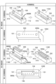
- FIG. 3 is a diagram showing a first and second configuration example of the optical connection assembly of the present disclosure (labeled "optical connection assembly 1" in FIG. 3).
- the upper part of FIG. 3 shows a specific configuration of the first arrangement example shown in the top row of FIG. 2.
- the lower part of FIG. 3 shows a specific configuration of the third arrangement example shown in the third row of FIG. 2.
- the first configuration example in the upper part of Figure 3 is a specific configuration of the first arrangement example in Figure 2.
- the optical connection assembly 100A includes a first optical connection part 110A made of glass, a second optical connection part 120A made of a ductile material, and a positioning structure that maintains the relative positional relationship between the first optical connection part 110A and the second optical connection part 120A.
- the first optical connection part 110A is mounted on the optical IC substrate 30.
- the core 510 provided in the glass substrate of the first optical connection part 110A extends from the surface facing the optical input/output part of the optical IC to the first reference surface 600a with the first end optically coupled to the optical input/output part of the optical IC.
- the glass substrate of the first optical connection part 110A is provided with a guide pin 150.
- the second optical connection part 120A is attached to the tip portion of the optical fiber 500 provided with a bent portion, and functions as a ferrule made of a ductile material.
- the second optical connection part 120A is provided with a guide hole 151 into which the guide pin 150 of the first optical connection part 110A is inserted.
- the end face of the optical fiber 500 is arranged on the second reference surface 600b of the second optical connection part 120A facing the first optical connection part 110A.
- a positioning structure is formed by the guide pin 150 of the first optical connecting part 110A and the guide hole 151 of the second optical connecting part 120A.
- the first optical connection part 110A and the second optical connection part 120A having the above-mentioned structure are vertically connected in a positioned state by inserting the guide pin 150 into the guide hole 151.
- the second configuration example in the lower part of Figure 3 is a specific configuration of the third arrangement example in Figure 2.
- the optical connection assembly 100C includes a first optical connection part 110C made of glass, a second optical connection part 120C made of a ductile material, and a positioning structure that maintains the relative positional relationship between the first optical connection part 110C and the second optical connection part 120C.
- the first optical connection part 110C is mounted on the optical IC substrate 30.
- the core 510 provided in the glass substrate of the first optical connection part 110C has a first end located on the first reference surface 600a, and a second end extending to the front of the inclined surface of the glass substrate on which the reflecting part 152 is arranged.
- the reflecting part 152 reflects light from the second end of the core 510 toward the optical input/output part of the optical IC, and also reflects light from the optical input/output part of the optical IC toward the second end of the core 510, thereby optically coupling the core 510 and the optical input/output part of the optical IC.
- the glass substrate of the first optical connection part 110C is provided with a guide pin 150.
- the second optical connection part 120C is attached to the tip portion of the optical fiber 500 and functions as a ferrule made of a ductile material.
- the second optical connection part 120C is provided with a guide hole 151 into which the guide pin 150 of the first optical connection part 110C is inserted.
- the end face of the optical fiber 500 is disposed on the second reference surface 600b of the second optical connecting part 120C, which faces the first optical connecting part 110C.
- the guide pin 150 of the first optical connecting part 110C and the guide hole 151 of the second optical connecting part 120C form a positioning structure.
- the first optical connection part 110C and the second optical connection part 120C having the above-mentioned structure are connected horizontally in a positioned state by inserting the guide pin 150 into the guide hole 151.
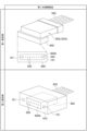
- FIG. 4 shows a third configuration example of the optical connection assembly of the present disclosure and its cross-sectional view (labeled "optical connection assembly 2" in FIG. 4).
- the upper part of FIG. 4 shows a specific configuration of the second arrangement example shown in the second part of FIG. 2.
- the lower part of FIG. 4 shows the cross-sectional structure of the optical connection assembly taken along line I-I shown in the upper part of FIG. 4.
- the third configuration example in the upper part of Figure 4 is a specific configuration of the second arrangement example in Figure 2.
- the optical connection assembly 100E includes a first optical connection part 110E made of glass, a second optical connection part 120E made of a ductile material, and a positioning structure that maintains the relative positional relationship between the first optical connection part 110E and the second optical connection part 120E.
- the first optical connection part 110E is adhesively fixed to a ferrule 300 attached to the tip of an optical fiber 500 having a bent portion.
- the end face of the optical fiber 500 is arranged on the end face of the ferrule 300, and the optical fiber 500 is optically connected to a core 510 provided inside the glass substrate of the first optical connection part 110E.
- the core 510 of the first optical connection part 110E extends from a surface facing the ferrule end face to a first reference surface 600a with the first end optically coupled to the optical fiber 500.
- the glass substrate of the first optical connection part 110E is provided with guide pins 150.
- a lens array 400 having a lens surface 410 corresponding one-to-one to the core 510 is adhesively fixed to the region of the first reference surface 600a between the guide pins 150 and where the second end of the core 510 is located.
- the second optical connecting part 120E is mounted on the optical IC substrate 30.
- the second optical connecting part 120E has an opening 154 extending from a second reference surface 600b facing the first optical connecting part 110E toward the optical IC.
- the second reference surface 600b of the second optical connecting part 120E has guide holes 151 into which the guide pins 150 of the first optical connecting part 110E are inserted, so as to sandwich the opening 154.
- the guide pins 150 of the first optical connecting part 110E and the guide holes 151 of the second optical connecting part 120E form a positioning structure.
- the first optical connecting part 110E and the second optical connecting part 120E having the above-mentioned structure are vertically connected in a positioned state by inserting the guide pin 150 into the guide hole 151.
- the lower part of Figure 4 shows a cross-sectional view of a third configuration example including an optical connecting assembly 100E in which the first optical connecting part 110E and the second optical connecting part 120E are vertically connected on the optical IC substrate 30.
- the second optical connection part 120E having the opening 154 is mounted on the optical IC substrate 30, and the guide pin 150 is inserted into the guide hole 151 with the first reference surface 600a and the second reference surface 600b in contact.
- the second optical connection part 120E is arranged on the optical IC substrate 30, the first optical connection part 110E is arranged on the second optical connection part 120E, and a layered structure is realized in which the ferrule 300 is arranged on the first optical connection part 110E.
- the lens array 400 adhesively fixed to the glass substrate of the first optical connection part 110E and the lens 155 arranged in the optical input/output part of the optical IC are located in the space defined by the opening 154 of the second optical connection part 120E.
- the lens surfaces 410 of the lens array 400 and the lenses 155 of the optical IC substrate 30 correspond one-to-one, and each functions as a collimating lens.
- FIG. 5 is a diagram showing a specific configuration of a set of a first optical connection part and a second optical connection part for each of the first and third configuration examples of the optical connection assembly of the present disclosure (indicated as "optical connection parts" in FIG. 5).
- the upper two rows (indicated as “first configuration example” in FIG. 5) show examples of the first optical connection part and the second optical connection part of the first configuration example shown in the upper row of FIG. 3, and the lower two rows (indicated as "third configuration example” in FIG. 5) show examples of the first optical connection part and the second optical connection part of the third configuration example shown in the upper row of FIG. 4.
- the top row (indicated as "first optical connection part” in FIG.
- the fourth row shows an assembly process of the first optical connection part made of a glass material, which is applied to the first configuration example.
- the second row (indicated as “second optical connection part” in FIG. 5) shows a front configuration of the second optical connection part made of a ductile material, which is applied to the first configuration example.
- the third row (labeled "first optical connection part” in FIG. 4) shows the assembly process of the first optical connection part applied to the third configuration example.
- the bottom row shows the front configuration of the second optical connection part applied to the third configuration example.
- the first optical connecting part 110A applied to the first configuration example shown in the upper part of Figure 3 is manufactured as shown in the top part of Figure 5. That is, a plurality of cores 510 extending from the first reference surface 600a to the surface facing the optical IC substrate 30 are formed in the glass substrate 111 which becomes the first optical connecting part 110A. Also, a pin insertion port 112 is formed in the first reference surface 600a, and a guide pin 150 is adhesively fixed thereto. That is, adhesive 113 is filled between the pin insertion port 112 and the guide pin 150, and thus the guide pin 150 is provided in the first optical connecting part 110A.
- a through hole for inserting the optical fiber is formed in the glass substrate 111.
- This through hole is formed using a process that combines photolithography and dry etching such as RIE (Reactive Ion Etching) or a hole drilling technique using a laser.
- RIE Reactive Ion Etching
- any glass hole drilling technique can be applied as long as the error of the position of the through hole from the specified design position is 1 ⁇ m or less, and the inner diameter of the through hole can be within ⁇ 1 ⁇ m or less from the target inner diameter.
- the through hole for inserting the optical fiber provided in the glass substrate 111 does not have to be perpendicular to the first reference surface 600a of the glass substrate.
- the through hole is formed so that the first reference surface 600a of the glass substrate or the angle between the first reference surface 600a and the through hole is ⁇ , in other words, the through hole is formed so that the through hole is inclined at an angle of 90°- ⁇ , for example 8°, with respect to the normal direction of the first reference surface 600a, thereby effectively reducing reflection at the connection interface with the optical input/output part of the optical IC.
- the core 510 formed inside the glass substrate 111 may be a refractive index change region in which a refractive index change occurs due to laser irradiation.
- the material of the guide pin 150 may be a material having a thermal expansion coefficient of 10 times or less than that of the glass substrate 111. If a part of a material having a linear expansion coefficient significantly different from that of the glass material is provided on the glass substrate 111 as the guide pin 150, stress will be generated in the glass substrate 111 when it is inserted into the glass substrate 111 in a high temperature environment. As a result, there is a risk of the glass substrate 111 being damaged. Therefore, by selecting a material having a thermal expansion coefficient of 10 times or less than that of the glass material as the material of the guide pin 150, damage to the glass substrate 111 that becomes the first optical connection component 110A can be reduced.
- the guide pin 150 is adhesively fixed to the glass substrate 111 in a state where a part of the guide pin 150 is inserted into the pin insertion port 112 provided in the glass substrate 111 that becomes the first optical connection part 110A.
- the difference between the inner diameter of the pin insertion port 112 of the glass substrate 111 and the outer diameter of the guide pin 150 may be 2 ⁇ m or less, and adhesive 113 is filled between the inner circumference of the pin insertion port 112 and the outer circumference of the guide pin 150.
- the adhesive 113 may be a heat-resistant adhesive.
- the guide pin 150 that becomes the protrusion can be easily provided on the glass substrate 111.
- the difference between the inner diameter of the pin insertion port 112 of the glass substrate 111 and the outer diameter of the guide pin 150 may be 2 ⁇ m or less, or may be 1 ⁇ m or less.
- an optical fiber is embedded as the core 510, or a refractive index change region is formed by laser drawing.
- a flexible arrangement pattern such as a two-dimensional arrangement of the cores 510 as the optical propagation region can be realized.
- the fitting structure on the optical IC substrate 30 can be safely realized without damaging the glass substrate 111.
- the second optical connecting part 120A applied to the first configuration example shown in the upper part of Fig. 3 has a structure as shown in the second part of Fig. 5. That is, the second optical connecting part 120A functions as a ferrule attached to the tip part of the optical fiber 500, and the end face of the optical fiber 500 and the guide hole 151 into which the guide pin 150 is inserted are arranged on the second reference surface 600b facing the first reference surface 600a of the first optical connecting part 110A.
- the ductile material of the second optical connecting part 120A may be a material mainly composed of a metal having a linear thermal expansion coefficient of 1 x 10 -6 /K or more and 7 x 10 -6 /K or less.
- the material of the second optical connecting part 120A may be a metal whose thermal expansion coefficient is approximately the same as that of silicon.
- the material of the second optical connecting part 120A is, for example, Kovar having a linear expansion coefficient of 5 ⁇ 10 ⁇ 6 /K or less, Invar having a linear expansion coefficient of 2 ⁇ 10 ⁇ 6 /K or less, a metal ceramic composite material, or the like.
- the first optical connection part 110E applied to the third configuration example shown in the upper part of FIG. 4 is manufactured as shown in the third part of FIG. 5. That is, a plurality of cores 510 extending from the first reference surface 600a to the surface facing the optical IC substrate 30 are formed in the glass substrate 111 that becomes the first optical connection part 110E. Also, a pin insertion port 112 is formed in the first reference surface 600a, and the guide pin 150 is adhesively fixed thereto. That is, the space between the pin insertion port 112 and the guide pin 150 is filled with adhesive 113, and thus the guide pin 150 is provided in the first optical connection part 110A.
- This configuration is the same as the manufacturing process of the first optical connection part 110A described above.
- the lens array 400 is adhesively fixed on the first reference surface 600a.
- This lens array 400 has a lens surface 410 that corresponds one-to-one to the plurality of cores 510 provided inside the glass substrate 111.
- the formation of the cores 510 in this first optical connecting part 110E and the material of the guide pins 150 are the same as in the case of the first optical connecting part 110A described above.
- the lens array 400 by appropriately bonding the lens array 400 to the glass substrate 111 that becomes the first optical connecting part 110E, it becomes possible to convert the light from the multiple cores 510 provided inside the glass substrate 111 into a predetermined beam and propagate it spatially.
- the second optical connection part 120E applied to the third configuration example shown in the upper part of FIG. 4 has a structure as shown in the bottom part of FIG. 5.
- the second optical connection part 120E is provided with an opening 154 that defines a space for propagating light from the core 510 of the first optical connection part 110E.
- This opening 154 surrounds the optical input/output part of the optical IC, and a lens 155 is disposed at the optical input/output part of the optical IC.
- the second optical connection part 120E is also provided with guide holes 151 on either side of the opening 154.
- the second optical connection part 120E is made of the same material as the second optical connection part 120A described above.
- FIG. 6 shows a fourth configuration example of the optical connection assembly of the present disclosure and its front view (labeled "optical connection assembly 3" in FIG. 6).
- the upper part of FIG. 6 shows a fourth configuration example in which a structure for stabilizing the optical connection state is added to the first configuration example shown in the upper part of FIG. 3.
- the lower part of FIG. 6 shows a front view of the fourth configuration example when viewed from the direction indicated by arrow A shown in the upper part of FIG. 6.
- the fourth configuration example in the upper part of Figure 6 includes the entirety of the first configuration example shown in the upper part of Figure 3. However, in addition to the first configuration example, this fourth configuration example includes a structure for maintaining the mated state of the first optical connecting part 110A and the second optical connecting part 120A. The maintenance of such a mated state is achieved by the clip member 700.
- the optical connection assembly 100A includes a first optical connection part 110A made of glass, a second optical connection part 120A made of a ductile material, and a positioning structure that maintains the relative positional relationship between the first optical connection part 110A and the second optical connection part 120A.
- the first optical connection part 110A mounted on the optical IC board 30 has a core 510 provided in its glass board, and a guide pin 150 provided on the first reference surface 600a.
- the second optical connection part 120A provided at the tip portion of the optical fiber 500 has a guide hole 151 into which the guide pin 150 of the first optical connection part 110A is inserted, and the end face of the optical fiber 500 is disposed on the second reference surface 600b.
- the guide pin 150 of the first optical connection part 110A and the guide hole 151 of the second optical connection part 120A form a positioning structure.
- the first optical connection part 110A and the second optical connection part 120A having such a structure are vertically connected in a positioned state by inserting the guide pin 150 into the guide hole 151.
- this fourth configuration example includes a clip member 700 as a structure for maintaining the fitted state of the first optical connecting part 110A and the second optical connecting part 120A.
- the clip member 700 has a main body 730 that grips the second optical connection part 120A while applying a biasing force to the second optical connection part 120A, hooks 720 provided on both ends of the main body 730, and a cushion member 710 for protecting the surface of the gripped second optical connection part 120A.
- the main body 730 is formed in a U-shape. More specifically, the main body 730 has a first portion 731 formed along the first direction A1 and a pair of second portions 732 formed along the second direction A2.
- the second direction A2 intersects (orthogonal in this example) with the first direction A1.
- the first portion 731 and the pair of second portions 732 are each formed in a rectangular plate shape.
- the longitudinal direction of the first portion 731 is along the first direction A1.
- the longitudinal direction of the second portion 732 is along the second direction A2.
- the first end of each second portion 732 in the second direction A2 is connected to the corresponding end of the first portion 731 in the first direction A1.
- the hook portion 720 is provided at a second end (an end not connected to the first portion 731) different from the first end of each second portion 732 in the second direction A2.
- the first optical connecting part 110A is provided in one-to-one correspondence with the hook part 720, and has a step part 450 against which the hook part 720 abuts when the main body 730 grips the second optical connecting part 120A.
- the mating state of the first optical connecting part 110A and the second optical connecting part 120A is realized by inserting the guide pin 150 into the guide hole 151 until the first reference surface 600a of the first optical connecting part 110A abuts the second reference surface 600b of the second optical connecting part 120A.
- the hook part 720 of the clip member 700 gripping the second optical connecting part 120A fits into the step part 450 of the first optical connecting part 110A, and the mating state of the first optical connecting part 110A and the second optical connecting part 120A is stably maintained.
- the first portion 731 has a surface 731a that faces the second optical connecting part 120A when the main body 730 holds the second optical connecting part 120A.
- the cushion member 710 is disposed on the surface 731a.
- the length from the top of the main body 730 of the clip member 700 to the hook portion 720 (the length from the first end of the second portion 732 to the hook portion 720) is shorter than the sum of the thickness of the cushion member 710, the thickness of the second optical connecting part 120A, and the thickness from the first reference surface 600a of the first optical connecting part 110A to the step portion 450.
- the cushion member 710 contacts the surface of the second optical connecting part 120A.
- the thickness of the cushion member 710 shrinks to generate a biasing force.
- the Young's modulus of the cushion member 710 may be 100 MPa or more and 40 GPa or less.
- the Young's modulus of the cushion member 710 can be measured using the weight loading method, tuning fork measurement method, etc.
- FIG. 7 shows a fifth configuration example of the optical connection assembly of the present disclosure and its front view (labeled "Optical Connection Assembly 4" in FIG. 7).
- the upper part of FIG. 7 shows a fifth configuration example in which a structure for stabilizing the optical connection state is added to the third configuration example shown in the upper part of FIG. 4.
- the lower part of FIG. 7 shows a front view of the fifth configuration example when viewed from the direction indicated by arrow A shown in the upper part of FIG. 7.
- the fifth configuration example in the upper part of FIG. 7 includes the entirety of the third configuration example shown in the upper part of FIG. 4. However, in addition to the third configuration example, this fifth configuration example includes a structure for maintaining the interlocking state of the first optical connecting part 110E and the second optical connecting part 120E. The maintenance of this interlocking state is achieved by the clip member 700.
- the optical connection assembly 100E includes a first optical connection part 110E made of glass, a second optical connection part 120E made of a ductile material, and a positioning structure that maintains the relative positional relationship between the first optical connection part 110E and the second optical connection part 120E.
- the first optical connection part 110E is adhesively fixed to a ferrule 300 attached to the tip portion of the optical fiber 500.
- the first optical connection part 110E has a core 510 provided therein, and a lens array 400 having a guide pin 150 and a lens surface 410 is adhesively fixed to the first reference surface 600a.
- the second optical connection part 120E is mounted on the optical IC substrate 30.
- the second optical connection part 120E has an opening 154 and guide holes 151 provided on the second reference surface 600b so as to sandwich the opening 154.
- the guide pin 150 of the first optical connecting part 110E and the guide hole 151 of the second optical connecting part 120E form a positioning structure.
- this fifth configuration example as in the fourth configuration example described above, the guide pin 150 of the first optical connecting part 110E is detachably fitted into the guide hole 151 of the second optical connecting part 120E. In this case, there is a possibility that the guide pin 150 may unintentionally come out of the guide hole 151 during use. Therefore, this fifth configuration example includes a clip member 700 as a structure for maintaining the fitted state of the first optical connecting part 110E and the second optical connecting part 120E.
- the clip member 700 has a main body 730 that grips the first optical connection part 110E while applying a biasing force to the first optical connection part 110E adhesively fixed to the ferrule 300, hooks 720 provided at both ends of the main body 730, and a cushion member 710 for protecting the surface of the gripped first optical connection part 110E.
- the second optical connection part 120E has a step portion 460 that is provided in one-to-one correspondence with the hooks 720 and against which the hooks 720 abut when the main body 730 grips the first optical connection part 110E, as shown in the lower part of FIG. 7.
- the mating state of the first optical connection part 110E and the second optical connection part 120E is realized by inserting the guide pin 150 into the guide hole 151 until the first reference surface 600a of the first optical connection part 110E abuts the second reference surface 600b of the second optical connection part 120E. At this time, the hook portion 720 of the clip member 700 gripping the second optical connecting part 120E fits into the step portion 460 of the first optical connecting part 110E, and the fitted state between the first optical connecting part 110E and the second optical connecting part 120E is stably maintained.
- the surface 731a of the first portion 731 faces the first optical connecting part 110E when the main body 730 grips the first optical connecting part 110E.
- the cushion member 710 is disposed on the surface 731a.
- the length from the top of the main body 730 of the clip member 700 to the hook portion 720 (the length from the first end of the second portion 732 to the hook portion 720) is shorter than the sum of the thickness of the cushion member 710, the thickness of the first optical connecting part 110E, and the thickness from the second reference surface 600b to the step portion 460 of the second optical connecting part 120E.
- the cushion member 710 contacts the surface of the first optical connecting part 110E.
- the thickness of the cushion member 710 shrinks to generate a biasing force.
- the Young's modulus of the cushion member 710 may be 100 MPa or more and 40 GPa or less.
- the Young's modulus of the cushion member 710 can be measured using the weight loading method, tuning fork measurement method, etc.
- the relationship L1 ⁇ L2 ⁇ L3 may be satisfied in order to avoid damage to the first optical connecting part 110E as described above.
- FIG. 8 is a diagram showing a modified example of the second optical connection part functioning as a ferrule in the first, second, or fourth configuration example of the optical connection assembly of the present disclosure (denoted as "second optical connection part" in FIG. 8).
- the upper part of FIG. 8 shows a first modified example of the second optical connection part shown in FIG. 2, FIG. 3, FIG. 5, etc.
- the lower part of FIG. 8 shows a second modified example of the second optical connection part shown in FIG. 2, FIG. 3, FIG. 5, etc.
- the first optical connection part made of glass is disposed on the optical IC board
- the second optical connection part made of a ductile material is disposed on the opposite side of the optical IC board from the first optical connection part.
- the second optical connection part is composed of a member of a different ductile material.
- the example of the second optical connection part shown in the upper row of FIG. 8 includes a ferrule part 350 having a structure similar to that of the second optical connection part 120A of the first configuration example, and a metal frame 800 surrounding the tip part of the ferrule part 350 including the second reference surface 600b.
- the end face of the optical fiber 500 is disposed on the second reference surface 600b surrounded by the metal frame 800 mainly composed of metal, and guide holes 151 are provided to sandwich these end faces.
- the material of the metal frame 800 may be a material mainly made of metal having a linear thermal expansion coefficient of 1 ⁇ 10 ⁇ 6 /K or more and 7 ⁇ 10 ⁇ 6 /K or less.
- the material of the metal frame 800 may be a metal having a thermal expansion coefficient that is approximately equal to that of silicon, and may be, for example, Kovar having a linear expansion coefficient of 5 ⁇ 10 ⁇ 6 /K or less, Invar having a linear expansion coefficient of 2 ⁇ 10 ⁇ 6 /K or less, or a metal ceramic composite material.
- the material mainly made of metal contains 30% or more of metal.
- the material of the ferrule portion 350 may be a resin material having a linear thermal expansion coefficient of 3 ⁇ 10 ⁇ 5 /K or less.
- the material of the ferrule portion 350 may be, for example, a liquid crystal polymer having a linear expansion coefficient of 1 ⁇ 10 ⁇ 5 /K or less, or PPS having a linear expansion coefficient of 2.5 ⁇ 10 ⁇ 5 /K or less.
- the guide hole 151 into which the guide pin 150 is inserted may be provided in either the resin part or the metal part.
- the lower part of Figure 8 shows an example of a second optical connection part in which a ferrule part 360 having a guide hole 151 attached to the tip part of an optical fiber 500 is surrounded by a metal frame 810 with the second reference surface 600b exposed. The optical fiber 500 is disposed on the second reference surface 600b, while the guide hole 151 is provided in the metal frame 810.
- the frame surrounding the tip of the ferrule portion 350, 360 is made of a material mainly composed of a metal having a thermal expansion coefficient that is equal to or close to that of silicon. This reduces the thermal deformation of the resin ferrule portion 350, 360, and reduces damage caused by the insertion of the guide pin 150.
- the resin material of the ferrule portion 350, 360 has a larger thermal expansion coefficient than silicon, so there is a risk of peeling or the like occurring when it is directly bonded to the silicon of the optical IC substrate. Therefore, in the configuration example of the optical connection assembly to which the second optical connection part is applied shown in the upper and lower examples of FIG. 8, the first optical connection part is disposed on the optical IC substrate. In this case, by inserting the guide pin 150 into the guide hole 151 provided in the resin ferrule portion 350 or the metal frame 810, a stable fitting structure can be realized even on the optical IC substrate that is greatly affected by heat.
Landscapes
- Physics & Mathematics (AREA)
- General Physics & Mathematics (AREA)
- Optics & Photonics (AREA)
- Optical Couplings Of Light Guides (AREA)
- Mechanical Coupling Of Light Guides (AREA)
- Light Receiving Elements (AREA)
Priority Applications (2)
| Application Number | Priority Date | Filing Date | Title |
|---|---|---|---|
| JP2025513847A JPWO2024214484A1 (https=) | 2023-04-13 | 2024-03-15 | |
| CN202480024950.XA CN121057969A (zh) | 2023-04-13 | 2024-03-15 | 光连接组件 |
Applications Claiming Priority (2)
| Application Number | Priority Date | Filing Date | Title |
|---|---|---|---|
| JP2023-065819 | 2023-04-13 | ||
| JP2023065819 | 2023-04-13 |
Publications (1)
| Publication Number | Publication Date |
|---|---|
| WO2024214484A1 true WO2024214484A1 (ja) | 2024-10-17 |
Family
ID=93059120
Family Applications (1)
| Application Number | Title | Priority Date | Filing Date |
|---|---|---|---|
| PCT/JP2024/010317 Ceased WO2024214484A1 (ja) | 2023-04-13 | 2024-03-15 | 光接続アセンブリ |
Country Status (4)
| Country | Link |
|---|---|
| JP (1) | JPWO2024214484A1 (https=) |
| CN (1) | CN121057969A (https=) |
| TW (1) | TW202447260A (https=) |
| WO (1) | WO2024214484A1 (https=) |
Citations (11)
| Publication number | Priority date | Publication date | Assignee | Title |
|---|---|---|---|---|
| JP2003344713A (ja) * | 2002-05-29 | 2003-12-03 | Kyocera Corp | 光素子モジュール及びその製造方法 |
| JP2004240220A (ja) * | 2003-02-06 | 2004-08-26 | Seiko Epson Corp | 光モジュール及びその製造方法、混成集積回路、混成回路基板、電子機器、光電気混載デバイス及びその製造方法 |
| US20130216190A1 (en) * | 2012-02-20 | 2013-08-22 | Tyco Electronics Corporation | Optical assembly with ferrule and frame |
| JP2015512531A (ja) * | 2012-04-05 | 2015-04-27 | ナノプレシジョン プロダクツ インコーポレイテッドNanoprecision Products, Inc. | 位置合わせピンをクランプ留めするための対応構造を有する、光ファイバコネクタ用のフェルール |
| JP2016009081A (ja) * | 2014-06-24 | 2016-01-18 | 富士通コンポーネント株式会社 | 光コネクタの製造方法及び光コネクタ |
| JP2019008173A (ja) * | 2017-06-26 | 2019-01-17 | 住友電気工業株式会社 | 光接続デバイス、光処理装置、光接続デバイスを作製する方法 |
| US10330872B2 (en) * | 2015-11-24 | 2019-06-25 | Hewlett Packard Enterprise Development Lp | Interfacing a ferrule with a socket |
| WO2020027125A1 (ja) * | 2018-08-01 | 2020-02-06 | 住友電気工業株式会社 | 光接続部品 |
| JP2020098319A (ja) * | 2018-12-14 | 2020-06-25 | 株式会社フジクラ | フェルール、ファイバ付きフェルール及びファイバ付きフェルールの製造方法 |
| US11112574B1 (en) * | 2020-04-30 | 2021-09-07 | Hewlett Packard Enterprise Development Lp | Optoelectronic system with a wedge-shaped adapter |
| JP2022509356A (ja) * | 2018-10-23 | 2022-01-20 | クードクアンタ フロリダ インコーポレイテッド | フォトニック集積回路用のマイクロミラー光学ベンチを備えた取外し可能なエッジカプラ |
-
2024
- 2024-03-15 JP JP2025513847A patent/JPWO2024214484A1/ja active Pending
- 2024-03-15 WO PCT/JP2024/010317 patent/WO2024214484A1/ja not_active Ceased
- 2024-03-15 CN CN202480024950.XA patent/CN121057969A/zh active Pending
- 2024-04-08 TW TW113112942A patent/TW202447260A/zh unknown
Patent Citations (11)
| Publication number | Priority date | Publication date | Assignee | Title |
|---|---|---|---|---|
| JP2003344713A (ja) * | 2002-05-29 | 2003-12-03 | Kyocera Corp | 光素子モジュール及びその製造方法 |
| JP2004240220A (ja) * | 2003-02-06 | 2004-08-26 | Seiko Epson Corp | 光モジュール及びその製造方法、混成集積回路、混成回路基板、電子機器、光電気混載デバイス及びその製造方法 |
| US20130216190A1 (en) * | 2012-02-20 | 2013-08-22 | Tyco Electronics Corporation | Optical assembly with ferrule and frame |
| JP2015512531A (ja) * | 2012-04-05 | 2015-04-27 | ナノプレシジョン プロダクツ インコーポレイテッドNanoprecision Products, Inc. | 位置合わせピンをクランプ留めするための対応構造を有する、光ファイバコネクタ用のフェルール |
| JP2016009081A (ja) * | 2014-06-24 | 2016-01-18 | 富士通コンポーネント株式会社 | 光コネクタの製造方法及び光コネクタ |
| US10330872B2 (en) * | 2015-11-24 | 2019-06-25 | Hewlett Packard Enterprise Development Lp | Interfacing a ferrule with a socket |
| JP2019008173A (ja) * | 2017-06-26 | 2019-01-17 | 住友電気工業株式会社 | 光接続デバイス、光処理装置、光接続デバイスを作製する方法 |
| WO2020027125A1 (ja) * | 2018-08-01 | 2020-02-06 | 住友電気工業株式会社 | 光接続部品 |
| JP2022509356A (ja) * | 2018-10-23 | 2022-01-20 | クードクアンタ フロリダ インコーポレイテッド | フォトニック集積回路用のマイクロミラー光学ベンチを備えた取外し可能なエッジカプラ |
| JP2020098319A (ja) * | 2018-12-14 | 2020-06-25 | 株式会社フジクラ | フェルール、ファイバ付きフェルール及びファイバ付きフェルールの製造方法 |
| US11112574B1 (en) * | 2020-04-30 | 2021-09-07 | Hewlett Packard Enterprise Development Lp | Optoelectronic system with a wedge-shaped adapter |
Also Published As
| Publication number | Publication date |
|---|---|
| CN121057969A (zh) | 2025-12-02 |
| TW202447260A (zh) | 2024-12-01 |
| JPWO2024214484A1 (https=) | 2024-10-17 |
Similar Documents
| Publication | Publication Date | Title |
|---|---|---|
| US10782474B2 (en) | Detachable optical connectors for optical chips comprising a connector support and methods of fabricating the same | |
| US10488602B2 (en) | Fiber-to-waveguide optical interface devices and coupling devices with lenses for photonic systems | |
| US11105981B2 (en) | Optical connectors and detachable optical connector assemblies for optical chips | |
| JP7559766B2 (ja) | 光ファイバ接続部品及び光ファイバ接続構造 | |
| CN112368616B (zh) | 光连接部件 | |
| US10191216B2 (en) | Fiber-to-waveguide optical interface device and components for photonic systems | |
| US20190064454A1 (en) | Glass-based ferrule assemblies and coupling apparatus for optical interface devices for photonic systems | |
| US20250052947A1 (en) | Bent optical fiber, method for manufacturing bent optical fiber, and optical connection component | |
| JP2018004830A (ja) | 高耐熱性光ファイバモジュールおよびその作製方法 | |
| WO2024214484A1 (ja) | 光接続アセンブリ | |
| JP4699262B2 (ja) | 光導波路コネクタ及びそれを用いた光接続構造、並びに光導波路コネクタの製造方法 | |
| TW202530777A (zh) | 光連接組件及安裝方法 | |
| CN112105977B (zh) | 光连接器部及光连接构造体 | |
| US20250110288A1 (en) | Optical connection terminal, connection structure for optical connection terminal, and method for making optical device | |
| US20230393348A1 (en) | Optical ferrule assemblies | |
| CN119065074A (zh) | 光模块 | |
| JPH10288718A (ja) | 光導波路デバイス |
Legal Events
| Date | Code | Title | Description |
|---|---|---|---|
| 121 | Ep: the epo has been informed by wipo that ep was designated in this application |
Ref document number: 24788514 Country of ref document: EP Kind code of ref document: A1 |
|
| WWE | Wipo information: entry into national phase |
Ref document number: 2025513847 Country of ref document: JP |
|
| NENP | Non-entry into the national phase |
Ref country code: DE |
|
| 122 | Ep: pct application non-entry in european phase |
Ref document number: 24788514 Country of ref document: EP Kind code of ref document: A1 |