WO2024204516A1 - 鋼材の炭化物形態検出装置、鋼材の炭化物形態検出方法及び鋼材の炭化物形態検出プログラム - Google Patents
鋼材の炭化物形態検出装置、鋼材の炭化物形態検出方法及び鋼材の炭化物形態検出プログラム Download PDFInfo
- Publication number
- WO2024204516A1 WO2024204516A1 PCT/JP2024/012601 JP2024012601W WO2024204516A1 WO 2024204516 A1 WO2024204516 A1 WO 2024204516A1 JP 2024012601 W JP2024012601 W JP 2024012601W WO 2024204516 A1 WO2024204516 A1 WO 2024204516A1
- Authority
- WO
- WIPO (PCT)
- Prior art keywords
- cross
- image data
- steel material
- data
- crystal grain
- Prior art date
- Legal status (The legal status is an assumption and is not a legal conclusion. Google has not performed a legal analysis and makes no representation as to the accuracy of the status listed.)
- Ceased
Links
Images








Classifications
-
- G—PHYSICS
- G06—COMPUTING OR CALCULATING; COUNTING
- G06V—IMAGE OR VIDEO RECOGNITION OR UNDERSTANDING
- G06V20/00—Scenes; Scene-specific elements
- G06V20/60—Type of objects
- G06V20/69—Microscopic objects, e.g. biological cells or cellular parts
- G06V20/698—Matching; Classification
-
- G—PHYSICS
- G01—MEASURING; TESTING
- G01N—INVESTIGATING OR ANALYSING MATERIALS BY DETERMINING THEIR CHEMICAL OR PHYSICAL PROPERTIES
- G01N33/00—Investigating or analysing materials by specific methods not covered by groups G01N1/00 - G01N31/00
- G01N33/20—Metals
- G01N33/204—Structure thereof, e.g. crystal structure
-
- G—PHYSICS
- G06—COMPUTING OR CALCULATING; COUNTING
- G06T—IMAGE DATA PROCESSING OR GENERATION, IN GENERAL
- G06T7/00—Image analysis
-
- G—PHYSICS
- G06—COMPUTING OR CALCULATING; COUNTING
- G06V—IMAGE OR VIDEO RECOGNITION OR UNDERSTANDING
- G06V10/00—Arrangements for image or video recognition or understanding
- G06V10/20—Image preprocessing
- G06V10/28—Quantising the image, e.g. histogram thresholding for discrimination between background and foreground patterns
-
- G—PHYSICS
- G06—COMPUTING OR CALCULATING; COUNTING
- G06V—IMAGE OR VIDEO RECOGNITION OR UNDERSTANDING
- G06V10/00—Arrangements for image or video recognition or understanding
- G06V10/40—Extraction of image or video features
- G06V10/42—Global feature extraction by analysis of the whole pattern, e.g. using frequency domain transformations or autocorrelation
- G06V10/422—Global feature extraction by analysis of the whole pattern, e.g. using frequency domain transformations or autocorrelation for representing the structure of the pattern or shape of an object therefor
-
- G—PHYSICS
- G06—COMPUTING OR CALCULATING; COUNTING
- G06V—IMAGE OR VIDEO RECOGNITION OR UNDERSTANDING
- G06V10/00—Arrangements for image or video recognition or understanding
- G06V10/88—Image or video recognition using optical means, e.g. reference filters, holographic masks, frequency domain filters or spatial domain filters
-
- G—PHYSICS
- G06—COMPUTING OR CALCULATING; COUNTING
- G06V—IMAGE OR VIDEO RECOGNITION OR UNDERSTANDING
- G06V20/00—Scenes; Scene-specific elements
- G06V20/60—Type of objects
- G06V20/69—Microscopic objects, e.g. biological cells or cellular parts
- G06V20/695—Preprocessing, e.g. image segmentation
Definitions
- the present invention relates to a device for detecting the carbide morphology of steel. Or, the present invention relates to a method for detecting the carbide morphology of steel. Or, the present invention relates to a program for detecting the carbide morphology of steel.
- Carbide morphology is used as one of the indices for evaluating the properties of steel materials.
- Patent Document 1 describes a method for manufacturing a steel part for bearings with excellent fatigue properties by heating a steel having a carbide morphology in the structure of spheroidized carbide with an average aspect ratio of 3 or less at an average heating rate of 0.5°C/s or more from Ac 3 point -10°C to Ac 3 point, at Ac 3 point or more and at Ac 3 point +130°C or less, with a holding time of 500 seconds or less at Ac 3 point or more, and then quenching the steel.
- the carbide morphology in steel is evaluated by exposing the steel structure through etching and observing it with a scanning electron microscope (SEM).
- SEM scanning electron microscope
- various structures including the surfaces of the crystal grains and the grain boundaries of the crystal grains are observed. For this reason, the carbide morphology in steel is evaluated based on the observer's experience and has not been provided as objective, quantified data.
- One of the objects of one embodiment of the present invention is to provide a detection device that can properly digitize the carbide morphology in steel.
- one of the objects of one embodiment of the present invention is to provide a detection method that can properly digitize the carbide morphology in steel.
- one of the objects of one embodiment of the present invention is to provide a detection program that can properly digitize the carbide morphology in steel.
- the carbide morphology detection device comprises an identification unit that identifies the cross-sectional area of the crystal grains that compose the steel material from a microscopic image of the steel material, an extraction unit that extracts image data of the cross-sectional area of the crystal grains from the microscopic image based on the identified cross-sectional area of the crystal grains, and a data conversion unit that binarizes the extracted image data.
- the carbide morphology detection device comprises a data conversion unit that binarizes image data of a microscopic image of a steel material, an identification unit that identifies the cross-sectional areas of the crystal grains that make up the steel material from the binarized image data, and an extraction unit that extracts image data of the cross-sectional areas of the crystal grains from the binarized image data based on the identified cross-sectional areas of the crystal grains.
- the identification unit may include a mask data generation unit that generates mask data from a microscopic image or binarized image data of the steel material, and the mask data generation unit generates mask data by setting a portion in the microscopic image or binarized image data that has a brightness value equal to or less than a first predetermined value as a portion to be masked, and the identification unit may identify a cross-sectional region of the crystal grains that make up the steel material based on the mask data.
- the identification unit may include a machine learning unit that trains a machine learning model using multiple microscopic images of steel material for training or multiple binarized image data for training, and the identification unit may input the microscopic images of the steel material or the binarized image data to the trained machine learning model to identify the cross-sectional area of the crystal grains that make up the steel material.
- the extraction unit may extract image data of the cross-sectional area of the crystal grain from the microscope image or the binarized image data.
- the data conversion unit may binarize the image data of the cross-sectional area of the crystal grain or the microscope image based on a second predetermined value.
- the carbide morphology detection method uses a carbide morphology detection device that includes an identification unit, an extraction unit, and a data conversion unit, in which the identification unit identifies the cross-sectional area of the crystal grains that make up the steel material from a microscopic image of the steel material, the extraction unit extracts image data of the cross-sectional area from the microscopic image based on the identified cross-sectional area of the crystal grain, and the data conversion unit binarizes the extracted image data to determine the structure of the carbide.
- the carbide morphology detection method uses a carbide morphology detection device that includes an identification unit, an extraction unit, and a data conversion unit, in which the data conversion unit binarizes image data of a microscopic image of a steel material, the identification unit identifies cross-sectional areas of crystal grains that make up the steel material from the binarized image data, and the extraction unit extracts image data of the cross-sectional areas of the crystal grains from the binarized image data based on the identified cross-sectional areas of the crystal grains, thereby determining the structure of the carbide.
- the identification unit may include a mask data generation unit, which generates mask data by setting portions in the microscope image or binarized image data having a brightness value equal to or less than a first predetermined value as portions to be masked, and the identification unit may identify cross-sectional regions of crystal grains that make up the steel material based on the mask data.
- a mask data generation unit which generates mask data by setting portions in the microscope image or binarized image data having a brightness value equal to or less than a first predetermined value as portions to be masked, and the identification unit may identify cross-sectional regions of crystal grains that make up the steel material based on the mask data.
- the identification unit may include a machine learning unit, which trains a machine learning model using multiple microscopic images of steel material for training or multiple binary image data for training, and the identification unit may input the microscopic images or binary image data of the steel material to the trained machine learning model to identify the cross-sectional area of the crystal grains that make up the steel material.
- the extraction unit may extract image data of the cross-sectional area of the crystal grain from the microscope image or the binarized image data.
- the data conversion unit may binarize the image data of the cross-sectional area of the crystal grain or the microscope image based on a second predetermined value.
- the carbide morphology detection program causes a computer to identify the cross-sectional areas of the crystal grains that make up the steel material from a microscopic image of the steel material, extract image data of the cross-sectional areas from the microscopic image based on the identified cross-sectional areas of the crystal grains, and binarize the extracted image data to determine the structure of the carbide.
- the carbide morphology detection program binarizes image data of a microscope image of a steel material, causes a computer to identify the cross-sectional areas of the crystal grains that make up the steel material from the binarized image data, and causes the computer to extract image data of the cross-sectional areas from the binarized image data based on the identified cross-sectional areas of the crystal grains, thereby determining the structure of the carbide.
- the computer may be caused to generate mask data from a microscopic image or binarized image data of the steel material, and the computer may be caused to set portions in the microscopic image or binarized image data having a brightness value equal to or less than a first predetermined value as portions to be masked, generating the mask data, and the computer may be caused to identify cross-sectional regions of the crystal grains that make up the steel material based on the mask data.
- the computer may be made to train a machine learning model using multiple microscopic images of steel material for training or multiple binary image data for training, and the computer may input the microscopic images or binary image data of the steel material into the trained machine learning model to identify the cross-sectional area of the crystal grains that make up the steel material.
- the computer may be configured to extract image data of the cross-sectional area of the crystal grain from the microscope image or the binarized image data.
- the computer may binarize the image data of the cross-sectional area of the crystal grain or the image data of the microscopic image based on a second predetermined value.
- One embodiment of the present invention provides a detection device that can properly digitize the carbide morphology in steel.
- one embodiment of the present invention provides a detection method that can properly digitize the carbide morphology in steel.
- one embodiment of the present invention provides a detection program that can properly digitize the carbide morphology in steel.
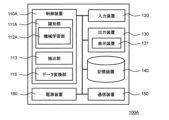
- FIG. 1 is a block diagram showing a carbide morphology detection device 100 according to an embodiment of the present invention.
- 1 is a block diagram showing a carbide form detection device 100A according to an embodiment of the present invention. This is an SEM image of the surface of a steel material whose structure has been exposed by etching.
- the left diagram is an enlarged view of area A, and is a binarized version of area A shown in the left diagram.
- the left diagram is an enlarged view of region B, which is a binarized version of region B shown in the left diagram.
- 1 is an SEM image of the surface of a steel material in which the structure of the steel material has been exposed by etching in one embodiment of the present invention.
- FIG. 4 is a diagram showing mask data according to an embodiment of the present invention.
- FIG. 2 is a diagram showing an extracted cross-sectional area of a crystal grain according to an embodiment of the present invention.
- FIG. 2 is a flow diagram of a carbide morphology detection method according to an embodiment of the present invention.
- FIG. 2 is a flow diagram of a carbide morphology detection method according to an embodiment of the present invention.
- FIG. 2 is a flow diagram of a carbide morphology detection method according to an embodiment of the present invention.
- FIG. 2 is a flow diagram of a carbide morphology detection method according to an embodiment of the present invention.
- FIG. 2 is a flow diagram of a carbide morphology detection method according to an embodiment of the present invention.
- FIG. 2 is a flow diagram of a carbide morphology detection method according to an embodiment of the present invention.
- FIG. 2 is a flow diagram of a carbide morphology detection method according to an embodiment of the present invention.
- FIG. 2 is a flow diagram of a carbide morphology detection method according to
- FIG. 2 is a flow diagram of a carbide morphology detection method according to an embodiment of the present invention.
- FIG. 2 is a flow diagram of a carbide morphology detection method according to an embodiment of the present invention.
- FIG. 2 is a flow diagram of a carbide morphology detection method according to an embodiment of the present invention.
- FIG. 2 is a flow diagram of a carbide morphology detection method according to an embodiment of the present invention.
- FIG. 2 is a flow diagram of a carbide morphology detection method according to an embodiment of the present invention.
- FIG. 2 is a flow diagram of a carbide morphology detection method according to an embodiment of the present invention.
- FIG. 2 is a flow diagram of a carbide morphology detection method according to an embodiment of the present invention.
- FIG. 2 is a flow diagram of a carbide morphology detection method according to an embodiment of the present invention.
- FIG. 2 is a flow diagram of a carbide morphology detection method according to an embodiment
- FIG. 2 is a flow diagram of a carbide morphology detection method according to an embodiment of the present invention.
- FIG. 2 is a flow diagram of a carbide morphology detection method according to an embodiment of the present invention.
- FIG. 2 is a flow diagram of a carbide morphology detection method according to an embodiment of the present invention.
- FIG. 2A is an SEM image of the surface of the steel material with the structure exposed by etching.
- region A shows the internal structure of the crystal grains.
- region B shows a state in which structures including the surfaces of the crystal grains and the grain boundaries of the crystal grains are mixed.
- the left image of FIG. 2B is an enlarged view of region A
- the left image of FIG. 2C is an enlarged view of region B.
- white linear particles are observed in region A showing the internal structure of the crystal grains. These white linear particles indicate carbides present inside the crystal grains.
- FIG. 2A and FIG. 2C although white linear particles are observed in region B, it is difficult to distinguish them from the surrounding structures.
- the right diagram of Figure 2B shows the result of binarizing area A shown in the left diagram of Figure 2B. Comparing the left diagram of Figure 2B with the right diagram of Figure 2B, it is clear that the binarized carbide in the right diagram of Figure 2B properly reflects the shape in the left diagram of Figure 2B. By binarizing the carbide structure, only the carbide information is properly extracted, and it can be seen that the binarized carbide information can be used as an index for evaluating the properties of steel.
- the right image in Figure 2C shows the result of binarizing region B shown in the left image in Figure 2C. Comparing the right image in Figure 2B, which shows the binarized carbide, with the right image in Figure 2C, which shows the binarized region B, it is clear that the structures shown in white are different, and it can be seen that information such as the surfaces of crystal grains and grain boundaries of crystal grains is included as noise in region B.
- [Carbide morphology detection device] 1A is a block diagram showing a carbide morphology detection device 100 according to an embodiment of the present invention.
- the carbide morphology detection device 100 includes, for example, a control device 110, an input device 120, an output device 130, a storage device 140, a communication device 150, and a power supply device 160.
- the carbide morphology detection device 100 further includes, for example, an identification unit 111, an extraction unit 113, and a data conversion unit 115.
- the control device 110 is composed of a known central processing unit (CPU), operating system (OS), and control programs or modules for controlling the carbide morphology detection device 100.
- the control device 110 may be provided as a single program including the OS and the control programs or modules.
- the control programs or modules constituting the control device 110 are stored in the storage device 140 and executed by the CPU.
- control device 110 is shown to have an identification unit 111, an extraction unit 113, and a data conversion unit 115.
- the identification unit 111, the extraction unit 113, and the data conversion unit 115 may not be included in the control device 110, but may be provided together with the control device 110.
- the identification unit 111 is configured with a program or module for identifying the cross-sectional area of the crystal grains constituting the steel material from the SEM image of the steel material.
- the program or module constituting the identification unit 111 is stored in the storage device 140 and executed by the CPU.
- the identification unit 111 includes a mask data generation unit 112.
- the mask data generation unit 112 is a program or module for generating mask data from the SEM image of the steel material, and is stored in the storage device 140 and executed by the CPU.
- the identification unit 111 includes the mask data generation unit 112, but the mask data generation unit 112 may be provided together with the identification unit 111 without being included in the identification unit 111.
- the identification unit 111 can identify the cross-sectional area of the crystal grains constituting the steel material based on the mask data generated by the mask data generation unit 112.
- the term "mask data" refers to data indicating an area to be excluded from the SEM image of the steel in order to identify the cross-sectional area of the crystal grains constituting the steel, which corresponds to the above-mentioned area A.
- the area to be excluded from the SEM image of the steel is an area including structures that become noise, such as the surfaces of the crystal grains and the grain boundaries of the crystal grains, which correspond to the above-mentioned area B.
- the mask data generating unit 112 can generate mask data by setting a portion in the SEM image having a brightness value equal to or less than a predetermined value (hereinafter also referred to as the first predetermined value) as a portion to be masked.
- the first predetermined value may be a brightness value previously set from the observation of the SEM image of the steel, or may be a brightness value set by the user for the actual SEM image of the steel that is processed by the mask data generating unit 112 and that is confirmed by the user on the display device 131.
- the average value of the brightness of the pixel of interest and the brightness of the pixels around it may be set as the first predetermined value (adaptive binarization).
- the extraction unit 113 is configured with a program or module for extracting image data of the cross-sectional area of the crystal grain from the SEM image based on the cross-sectional area of the crystal grain identified by the identification unit 111.
- the program or module configuring the extraction unit 113 is stored in the storage device 140 and executed by the CPU.
- the extraction unit 113 extracts image data of the cross-sectional area of the crystal grain from the SEM image based on the cross-sectional area of the crystal grain that constitutes the steel material identified by the identification unit 111.
- the extraction unit 113 extracts image data of the cross-sectional area of the crystal grain by subtracting an area including a noise structure from the SEM image based on the mask data generated by the mask data generation unit 112.
- the data conversion unit 115 is configured with a program or module for binarizing the image data extracted by the extraction unit 113.
- the program or module constituting the data conversion unit 115 is stored in the storage device 140 and executed by the CPU.
- the data conversion unit 115 binarizes the image data of the cross-sectional region of the crystal grain based on a predetermined value (hereinafter also referred to as the second predetermined value) in the image data of the cross-sectional region of the crystal grain.
- the brightness value of the part having a brightness equal to or greater than the second predetermined value (or greater than the second predetermined value) in the image data is converted to 1, and the brightness value of the part having a brightness less than the second predetermined value (or equal to or less than the second predetermined value) is converted to 0.
- the data conversion unit 115 can identify the part having a brightness value of 1 as a carbide structure.
- the second predetermined value may be a brightness value set in advance from the observation of the SEM image of the steel material, or may be a brightness value set by the user for the actual SEM image of the steel material to be processed by the data conversion unit 115, which the user confirmed on the display device 131.
- the average value of the luminance of the pixel of interest and the luminance of its surrounding pixels may be set as the second predetermined value (adaptive binarization).
- the input device 120 is a device for operating the carbide morphology detection device 100, and may be any known input device such as a keyboard, a mouse, or a touch panel disposed on a display device (e.g., a liquid crystal display or an organic EL display).
- the input device 120 may include a scanning electron microscope for acquiring the SEM image described above.
- the input device 120 may include a drive or reader such as a CD drive, DVD drive, or memory card reader to which media storing image data of the SEM image can be connected.
- the output device 130 includes a display device 131 that displays various images generated by the carbide morphology detection device 100.
- the display device 131 can display, for example, SEM images, mask data, cross-sectional areas of crystal grains that make up the steel material, binarized image data, etc.
- the display device 131 can be, for example, a liquid crystal display or an organic EL display, but is not limited to these.
- the output device 130 may also include a printer that prints the images displayed by the display device 131.
- the storage device 140 is a device that stores one or more programs or modules selected from the operating system (OS) and control programs or modules that constitute the control device 110, the programs or modules that constitute the identification unit 111, the programs or modules that constitute the mask data generation unit 112, the programs or modules that constitute the extraction unit 113, and the programs or modules that constitute the data conversion unit 115.
- the storage device 140 is composed of, for example, a known main storage device such as a random access memory (RAM) and known auxiliary storage devices such as a read-only memory (ROM), a hard disk, or a solid-state drive (SSD) and a memory card.
- the auxiliary storage device may be arranged outside the carbide morphology detection device 100 and arranged on a server or network drive that can communicate via the communication device 150.
- the communication device 150 is a known wired or wireless communication device that can be controlled by the control device 110.
- the communication device 150 can be connected to a communication network such as a local area network (LAN), a wide area network (WAN), or the Internet.
- the communication device 150 may be a communication device that conforms to a wireless communication standard such as Wi-Fi (registered trademark) (a communication means using the IEEE 802.11 standard) or Bluetooth (registered trademark).
- the communication device 150 may perform data communication with a server or a network drive located outside the carbide morphology detection device 100.
- the communication device 150 may include serial buses such as Universal Serial Bus (USB), PCI Express, and Serial ATA (SATA), and parallel buses such as Small Computer System Interface (SCSI) and Peripheral Component Interconnect (PCI).
- USB Universal Serial Bus
- SATA Serial ATA
- PCI Peripheral Component Interconnect
- the power supply unit 160 is a device that supplies external power to each device of the carbide morphology detection device 100, and is not particularly limited.
- the identification unit identifies the cross-sectional areas of the crystal grains constituting the steel material from a scanning electron microscope image of the steel material
- the extraction unit extracts image data of the cross-sectional areas of the crystal grains from the scanning electron microscope image based on the identified cross-sectional areas of the crystal grains
- the data conversion unit binarizes the extracted image data to determine the structure of the carbides.
- the carbide morphology detection device it is also possible to identify the cross-sectional areas of the crystal grains constituting the steel material after binarizing the scanning electron microscope image of the steel material.
- the data conversion unit 115 may be configured with a program or module for binarizing the SEM image of the steel.
- the data conversion unit 115 binarizes the SEM image of the steel based on a predetermined value (hereinafter also referred to as the second predetermined value) in the SEM image of the steel. More specifically, the brightness value of the part having a brightness equal to or greater than the second predetermined value (or greater than the second predetermined value) in the SEM image of the steel is converted to 1, and the brightness value of the part having a brightness less than the second predetermined value (or less than the second predetermined value) is converted to 0. By such processing, the data conversion unit 115 can determine the part having a brightness value of 1 as a structure that may be a carbide.
- the second predetermined value may be a brightness value set in advance from the observation of the SEM image of the steel, or may be a brightness value set by the user for the actual SEM image of the steel that the data conversion unit 115 processes and that the user has confirmed on the display device 131.
- the average value of the luminance of the pixel of interest and the luminance of its surrounding pixels may be set as the second predetermined value (adaptive binarization).
- the identification unit 111 is configured with a program or module for identifying the cross-sectional area of the crystal grains that make up the steel material from the image data that has been binarized by the data conversion unit 115.
- the mask data generation unit 112 is a program or module for generating mask data from the binarized image data.
- the identification unit 111 can identify the cross-sectional area of the crystal grains that make up the steel material based on the mask data generated by the mask data generation unit 112.
- the extraction unit 113 is configured with a program or module for extracting image data of the binarized cross-sectional region of the crystal grain based on the cross-sectional region of the crystal grain identified by the identification unit 111.
- the extraction unit 113 extracts image data of the cross-sectional region of the crystal grain from the binarized image data based on the cross-sectional region of the crystal grain constituting the steel material identified by the identification unit 111.
- the extraction unit 113 extracts image data of the cross-sectional region of the crystal grain by subtracting a region including a noise structure from the binarized image data based on the mask data generated by the mask data generation unit 112. Through such processing, the extraction unit 113 can determine the extracted region as a region where a carbide structure exists.
- FIG. 1B is a block diagram showing a carbide morphology detection device 100A according to one embodiment of the present invention.
- the carbide morphology detection device 100A includes, for example, a control device 110A, an input device 120, an output device 130, a storage device 140, a communication device 150, and a power supply device 160.
- the carbide morphology detection device 100A further includes, for example, an identification unit 111A, an extraction unit 113, and a data conversion unit 115.
- the configurations of the input device 120, the output device 130, the storage device 140, the communication device 150, the power supply device 160, the extraction unit 113, and the data conversion unit 115 are the same as those of the devices described for the carbide morphology detection device 100, and therefore detailed description thereof will be omitted.
- the control device 110A is composed of a known central processing unit (CPU), operating system (OS), and control programs or modules for controlling the carbide morphology detection device 100.
- the control device 110A may be provided as a single program including the OS and the control programs or modules.
- the control programs or modules constituting the control device 110A are stored in the storage device 140 and executed by the CPU.
- control device 110A is shown to have an identification unit 111A, an extraction unit 113, and a data conversion unit 115.
- identification unit 111A, the extraction unit 113, and the data conversion unit 115 may not be included in the control device 110A, but may be provided together with the control device 110A.
- the identification unit 111A is configured with a program or module for identifying the cross-sectional area of the crystal grains constituting the steel material from the SEM image of the steel material.
- the program or module constituting the identification unit 111A is stored in the storage device 140 and executed by the CPU.
- the identification unit 111A includes a machine learning unit 112A.
- the machine learning unit 112A is a program or module for learning a machine learning model, and is stored in the storage device 140 and executed by the CPU.
- the identification unit 111A includes the machine learning unit 112A, but the machine learning unit 112A may be provided together with the identification unit 111A without being included in the identification unit 111A.
- the identification unit 111A can identify the cross-sectional area of the crystal grains constituting the steel material based on the machine learning model learned by the machine learning unit 112A.
- the machine learning unit 112A trains a machine learning model using multiple SEM images of steel materials for training.
- the machine learning performed by the machine learning unit 112A may be supervised learning, unsupervised learning, or reinforcement learning, but in one embodiment, the machine learning model may be trained by supervised learning that provides the cross-sectional area of the crystal grains that make up the steel material in the SEM images used for training.
- the machine learning unit 112A may perform deep learning using a neural network. In another embodiment, the machine learning unit 112A may perform machine learning to identify the cross-sectional area of the crystal grains that make up the steel material using a Trainable Weka Segmentation (TWS) method. For example, features are extracted from the SEM image using multiple filters, and a feature vector is created for each pixel. A decision tree is trained as a machine learning model using the created feature vector, and a classifier based on the random forest method is created. Note that the random forest method is a technique in which multiple feature vectors obtained by filtering are randomly selected, and the vectors are identified based on the weighted average probability obtained by multiple decision trees. The created classifier is applied to the SEM image to perform classification by class.
- TWS Trainable Weka Segmentation
- the identification unit 111A can automatically identify the cross-sectional area of the crystal grains that make up the steel material by using the machine learning model learned by the machine learning unit 112A.
- the identification unit 111A may be configured with a program or module for identifying the cross-sectional area of the crystal grains that make up the steel material from the image data that has been binarized by the data conversion unit 115.
- the machine learning unit 112A trains a machine learning model using image data in which the data conversion unit 115 binarizes SEM images of multiple learning steel materials.
- the machine learning performed by the machine learning unit 112A may be supervised learning, unsupervised learning, or reinforcement learning, but in one embodiment, the machine learning model may be trained by supervised learning that provides the cross-sectional area of the crystal grains that make up the steel material in the binarized image data used for training.
- the machine learning unit 112A extracts features from the binarized image data using multiple filters, and creates a feature vector for each pixel.
- the created feature vector may be used to train a decision tree as a machine learning model, and a classifier based on the random forest method may be created. By applying the created classifier to the binarized image data, classification by class can be performed.
- the identification unit 111A can automatically identify the cross-sectional area of the crystal grains that make up the steel material by using the machine learning model learned by the machine learning unit 112A.
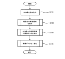
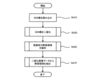
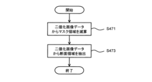
- FIGS. 4 to 7 are flow diagrams of a carbide morphology detection method according to one embodiment.
- the identification unit 111 reads an SEM image of the steel material (S110).
- the SEM image of the steel material may be read via the input device 120, or the identification unit 111 may read an SEM image stored in the storage device 140.
- the identification unit 111 may also read an SEM image stored in a server or network drive via a network connected to the communication device 150.
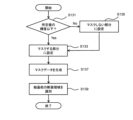
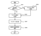
- the identification unit 111 identifies the cross-sectional area of the crystal grains that make up the steel from the read SEM image of the steel (S130). In one embodiment, the mask data generation unit 112 determines whether the pixels that make up the SEM image have a brightness value equal to or less than a first predetermined value (S131). The mask data generation unit 112 sets pixels that have a brightness value equal to or less than the first predetermined value as a portion to be masked (S133). The mask data generation unit 112 also sets pixels that have a brightness value higher than the first predetermined value as a portion not to be masked (S135). The mask data generation unit 112 synthesizes the portions set in this way and generates mask data from the SEM image (S137). The identification unit 111 can identify the cross-sectional area of the crystal grains that make up the steel based on the mask data (S139).
- the extraction unit 113 extracts image data of the cross-sectional area of the crystal grain from the SEM image based on the cross-sectional area of the crystal grain identified by the identification unit 111 (S150). Specifically, the extraction unit 113 subtracts a mask area including a noise structure from the SEM image based on the mask data generated by the mask data generation unit 112 (S151), and extracts image data of the cross-sectional area of the crystal grain (S153).
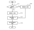
- the data conversion unit 115 binarizes the image data extracted by the extraction unit 113 (S170). Specifically, the data conversion unit 115 binarizes the image data of the cross-sectional region of the extracted crystal grain based on a second predetermined value for each pixel constituting the image data of the cross-sectional region of the crystal grain (S171). More specifically, the data conversion unit 115 converts the brightness value of a portion having a brightness equal to or greater than the second predetermined value (or greater than the second predetermined value) in the image data to 1 (S173), and converts the brightness value of a portion having a brightness less than the second predetermined value (or equal to or less than the second predetermined value) to 0 (S175).
- the data conversion unit 115 synthesizes the portions set in this way and generates image data in which the cross-sectional region of the crystal grain is binarized from the image data of the cross-sectional region of the crystal grain (S177). As a result, the data conversion unit 115 can identify the portion having a brightness value of 1 as a carbide structure.
- the second predetermined value may be a brightness value previously set based on observation of an SEM image of the steel material, or may be a brightness value set by the user for the actual SEM image of the steel material that is to be processed by the data conversion unit 115 and that the user has confirmed on the display device 131.
- the average value of the brightness of the pixel of interest and the brightness of the pixels surrounding it may be set as the second predetermined value (adaptive binarization).
- the identification unit identifies the cross-sectional areas of the crystal grains constituting the steel material from a scanning electron microscope image of the steel material
- the extraction unit extracts image data of the cross-sectional areas of the crystal grains from the scanning electron microscope image based on the identified cross-sectional areas of the crystal grains
- the data conversion unit binarizes the extracted image data to determine the structure of the carbides.
- the carbide morphology detection method according to the present invention it is also possible to identify the cross-sectional areas of the crystal grains constituting the steel material after binarizing the scanning electron microscope image of the steel material.
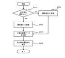
- the data conversion unit 115 reads the SEM image of the steel (S210). The process of reading the SEM image is the same as the process of S110 described above, so detailed description will be omitted.
- the data conversion unit 115 binarizes the SEM image of the steel (S230).
- the data conversion unit 115 binarizes the SEM image of the steel based on a predetermined value (hereinafter also referred to as the second predetermined value) in the SEM image of the steel (S231).
- the brightness value of a portion in the SEM image of the steel that has a brightness equal to or greater than the second predetermined value (or greater than the second predetermined value) is converted to 1 (S233), and the brightness value of a portion that has a brightness less than the second predetermined value (or less than the second predetermined value) is converted to 0 (S235).
- the data conversion unit 115 can determine that the portion having a brightness value of 1 is a structure that may be a carbide (S239).
- the second predetermined value may be a brightness value previously set from observation of an SEM image of the steel material, or may be a brightness value set by the user for the actual SEM image of the steel material that the data conversion unit 115 processes and that the user has confirmed using the display device 131.
- the average value of the brightness of the pixel of interest and the brightness of the pixels surrounding it may be set as the second predetermined value (adaptive binarization).
- the identification unit 111 identifies the cross-sectional area of the crystal grains constituting the steel material from the image data binarized by the data conversion unit 115 (S250).
- the mask data generation unit 112 judges whether the pixels constituting the binarized image data have a brightness value equal to or less than a first predetermined value (S251).
- the mask data generation unit 112 sets the pixels having a brightness value equal to or less than the first predetermined value as a portion to be masked (S253).
- the mask data generation unit 112 also sets the pixels having a brightness value higher than the first predetermined value as a portion not to be masked (S255).
- the mask data generation unit 112 synthesizes the portions set in this way and generates mask data from the binarized image data (S257).
- the identification unit 111 can identify the cross-sectional area of the crystal grains constituting the steel material in the binarized image data based on the mask data (S259).
- the extraction unit 113 extracts image data of the cross-sectional region of the crystal grain from the binarized image data based on the cross-sectional region of the crystal grain in the binarized image data identified by the identification unit 111 (S270). Specifically, the extraction unit 113 subtracts a mask region including a noise structure from the binarized image data based on the mask data generated by the mask data generation unit 112 (S271), and extracts image data of the cross-sectional region of the crystal grain (S273). As a result, the extraction unit 113 can identify the cross-sectional region of the crystal grain extracted from the binarized image data as a carbide structure.
- FIGS. 12 to 15 are flow diagrams of a carbide morphology detection method according to one embodiment.
- the identification unit 111A reads in an SEM image of the steel material (S310). The process of reading in the SEM image is the same as the process of S110 described above, so a detailed description will be omitted.
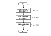
- the identification unit 111A identifies the cross-sectional area of the crystal grains that make up the steel material from the read SEM image of the steel material (S330).
- the machine learning unit 112A trains a machine learning model using multiple SEM images of steel material for training (S331).
- the machine learning performed by the machine learning unit 112A may be supervised learning, unsupervised learning, or reinforcement learning, but in one embodiment, the machine learning model may be trained by supervised learning that provides the cross-sectional area of the crystal grains that make up the steel material in the SEM image used for training.
- the machine learning unit 112A may perform deep learning using a neural network. In another embodiment, the machine learning unit 112A may perform machine learning using the TWS method to identify the cross-sectional area of the crystal grains that make up the steel material. For example, features are extracted from the SEM image using multiple filters, and a feature vector is created for each pixel. Using the created feature vector, a decision tree is trained as a machine learning model, and a classifier based on the random forest method is created. Note that the random forest method is a method of randomly selecting multiple feature vectors from multiple feature vectors obtained by filtering, and identifying them based on the weighted average probability obtained by multiple decision trees. The created classifier is applied to the SEM image to perform classification by class (S333). As a result, the machine learning unit 112A identifies the cross-sectional area of the crystal grains that make up the steel material (S335).
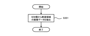
- the extraction unit 113 extracts image data of the cross-sectional area of the crystal grain from the SEM image based on the cross-sectional area of the crystal grain identified by the identification unit 111A (S150). Specifically, the extraction unit 113 extracts image data of the cross-sectional area of the crystal grain based on the cross-sectional area of the crystal grain identified by the identification unit 111A (S351).
- the data conversion unit 115 binarizes the image data extracted by the extraction unit 113 (S370). Specifically, the data conversion unit 115 binarizes the image data of the cross-sectional region of the extracted crystal grain based on the second predetermined value for each pixel constituting the image data of the cross-sectional region of the crystal grain (S371). More specifically, the data conversion unit 115 converts the brightness value of the part having a brightness equal to or greater than the second predetermined value (or greater than the second predetermined value) in the image data to 1 (S373), and converts the brightness value of the part having a brightness less than the second predetermined value (or equal to or less than the second predetermined value) to 0 (S375).
- the parts set in this way are combined, and the data conversion unit 115 generates image data in which the cross-sectional region of the crystal grain is binarized from the image data of the cross-sectional region of the crystal grain (S377).
- the data conversion unit 115 can identify the part having a brightness value of 1 as a carbide structure.
- the second predetermined value may be a brightness value previously set based on observation of an SEM image of the steel material, or may be a brightness value set by the user for the actual SEM image of the steel material that is to be processed by the data conversion unit 115 and that the user has confirmed on the display device 131.
- the average value of the brightness of the pixel of interest and the brightness of the pixels surrounding it may be set as the second predetermined value (adaptive binarization).
- FIGS. 16 to 19 are flow diagrams of the carbide morphology detection method according to one embodiment.
- the data conversion unit 115 reads the SEM image of the steel material (S410). The process of reading the SEM image is the same as the process of S110 described above, and therefore a detailed description is omitted.
- the data conversion unit 115 binarizes the SEM image of the steel material (S430).
- the data conversion unit 115 binarizes the SEM image of the steel material based on a predetermined value (hereinafter also referred to as a second predetermined value) in the SEM image of the steel material (S431). More specifically, the brightness value of a portion having a brightness equal to or greater than the second predetermined value (or greater than the second predetermined value) in the SEM image of the steel material is converted to 1 (S433), and the brightness value of a portion having a brightness less than the second predetermined value (or equal to or less than the second predetermined value) is converted to 0 (S435). Through such processing, the data conversion unit 115 can determine the portion having a brightness value of 1 as a structure that may be a carbide (S439).
- the second predetermined value may be a brightness value previously set from the observation of the SEM image of the steel material, or may be a brightness value set by the user for the actual SEM image of the steel material that is processed by the data conversion unit 115 and that is confirmed by the user through the display device 131.
- the average value of the brightness of the pixel of interest and the brightness of the pixels around it may be set as the second predetermined value (adaptive binarization).
- the identification unit 111A identifies the cross-sectional areas of the crystal grains that make up the steel from the image data that has been binarized by the data conversion unit 115 (S430).
- the machine learning unit 112A trains a machine learning model using multiple sets of binarized image data for learning (S431).
- the machine learning performed by the machine learning unit 112A may be supervised learning, unsupervised learning, or reinforcement learning, but in one embodiment, the machine learning model may be trained by supervised learning that provides the cross-sectional areas of the crystal grains that make up the steel in the SEM image used for learning.
- the machine learning unit 112A may perform deep learning using a neural network. In another embodiment, the machine learning unit 112A may perform machine learning to identify the cross-sectional area of the crystal grains that make up the steel material using a Trainable Weka Segmentation (TWS) method. For example, features are extracted from the SEM image using multiple filters, and a feature vector is created for each pixel. Using the created feature vector, a decision tree is trained as a machine learning model, and a classifier based on the random forest method is created. Note that the random forest method is a method of randomly selecting multiple feature vectors from multiple feature vectors obtained by filtering, and identifying them based on the weighted average probability obtained by multiple decision trees.
- TWS Trainable Weka Segmentation
- the created classifier is applied to the binarized image data to perform classification by class (S433).
- the machine learning unit 112A identifies the cross-sectional area of the crystal grains that make up the steel material in the binarized image data (S435).
- the extraction unit 113 extracts image data of the cross-sectional region of the crystal grain from the binarized image data based on the cross-sectional region of the crystal grain in the binarized image data identified by the identification unit 111A (S370). Specifically, the extraction unit 113 extracts image data of the cross-sectional region of the crystal grain from the binarized image data based on the cross-sectional region of the crystal grain identified by the identification unit 111A (S351). As a result, the extraction unit 113 can identify the cross-sectional region of the crystal grain extracted from the binarized image data as a carbide structure.
- Carbide morphology detection program In one embodiment of the present invention, a program for executing the above-mentioned carbide morphology detection method can be provided. Alternatively, in one embodiment, the program can be provided as a recording medium storing the program. The following description will be given with reference to FIGS. 4 to 7.
- This program causes the identification unit 111 to read an SEM image of the steel material (S110).
- the SEM image of the steel material may be read via the input device 120, or the identification unit 111 may read an SEM image stored in the storage device 140.
- the identification unit 111 may read an SEM image stored on a server or network drive via a network connected to the communication device 150.
- This program causes the identification unit 111 to identify the cross-sectional area of the crystal grains that make up the steel from the loaded SEM image of the steel (S130). In one embodiment, this program causes the mask data generation unit 112 to determine whether the pixels that make up the SEM image have a brightness value equal to or less than a first predetermined value (S131). This program causes the mask data generation unit 112 to set pixels that have a brightness value equal to or less than the first predetermined value as a portion to be masked (S133). This program also causes the mask data generation unit 112 to set pixels that have a brightness value higher than the first predetermined value as a portion not to be masked (S135).
- This program causes the portions set in this way to be combined, and causes the mask data generation unit 112 to generate mask data from the SEM image (S137).
- This program causes the identification unit 111 to identify the cross-sectional area of the crystal grains that make up the steel based on the mask data (S139).
- This program causes the extraction unit 113 to extract image data of the cross-sectional area of the crystal grain from the SEM image based on the cross-sectional area of the crystal grain identified by the identification unit 111 (S150). Specifically, this program causes the extraction unit 113 to subtract a mask area including a noise structure from the SEM image based on the mask data generated by the mask data generation unit 112 (S151), and extract image data of the cross-sectional area of the crystal grain (S153).
- This program causes the data conversion unit 115 to binarize the image data extracted by the extraction unit 113 (S170). Specifically, this program causes the data conversion unit 115 to binarize the image data of the cross-sectional region of the extracted crystal grain, using a second predetermined value as a reference for each pixel constituting the image data of the cross-sectional region of the crystal grain (S171).
- this program causes the data conversion unit 115 to convert the brightness value of a portion in the image data having a brightness equal to or greater than the second predetermined value (or greater than the second predetermined value) to 1 (S173), and to convert the brightness value of a portion having a brightness less than the second predetermined value (or equal to or less than the second predetermined value) to 0 (S175).
- This program synthesizes the portions set in this way, and causes the data conversion unit 115 to generate image data in which the cross-sectional region of the crystal grain is binarized from the image data of the cross-sectional region of the crystal grain (S177). As a result, this program causes the data conversion unit 115 to identify the portion having a brightness value of 1 as a carbide structure.
- the second predetermined value may be a brightness value previously set based on observation of an SEM image of the steel material, or may be a brightness value set by the user for the actual SEM image of the steel material that is to be processed by the data conversion unit 115 and that the user has confirmed on the display device 131.
- the average value of the brightness of the pixel of interest and the brightness of the pixels surrounding it may be set as the second predetermined value (adaptive binarization).
- the identification unit identifies the cross-sectional areas of the crystal grains constituting the steel material from a scanning electron microscope image of the steel material
- the extraction unit extracts image data of the cross-sectional areas of the crystal grains from the scanning electron microscope image based on the identified cross-sectional areas of the crystal grains
- the data conversion unit binarizes the extracted image data, thereby determining the structure of the carbide.
- This program causes the data conversion unit 115 to read the SEM image of the steel (S210).
- the process of reading the SEM image is the same as the process of S110 described above, so detailed description will be omitted.
- This program causes the data conversion unit 115 to binarize the SEM image of the steel (S230).
- This program causes the data conversion unit 115 to binarize the SEM image of the steel based on a predetermined value (hereinafter also referred to as the second predetermined value) in the SEM image of the steel (S231).
- this program converts the brightness value of a portion in the SEM image of the steel that has a brightness equal to or greater than the second predetermined value (or greater than the second predetermined value) to 1 (S233), and converts the brightness value of a portion that has a brightness less than the second predetermined value (or less than the second predetermined value) to 0 (S235).
- the program can cause the data conversion unit 115 to determine that a portion having a brightness value of 1 is a structure that may be a carbide (S239).
- the second predetermined value may be a brightness value previously set from observation of an SEM image of the steel material, or may be a brightness value set by the user for the actual SEM image of the steel material that the data conversion unit 115 processes and that the user has confirmed using the display device 131.
- the average value of the brightness of the pixel of interest and the brightness of the pixels surrounding it may be set as the second predetermined value (adaptive binarization).
- This program causes the identification unit 111 to identify the cross-sectional area of the crystal grains constituting the steel material from the image data binarized by the data conversion unit 115 (S250).
- this program causes the mask data generation unit 112 to determine whether the pixels constituting the binarized image data have a brightness value equal to or less than a first predetermined value (S251).
- This program causes the mask data generation unit 112 to set pixels having a brightness value equal to or less than the first predetermined value as a portion to be masked (S253).
- This program also causes the mask data generation unit 112 to set pixels having a brightness value higher than the first predetermined value as a portion not to be masked (S255).
- This program causes the portions set in this way to be combined, and causes the mask data generation unit 112 to generate mask data from the binarized image data (S257).
- This program causes the identification unit 111 to identify the cross-sectional area of the crystal grains constituting the steel material in the binarized image data based on the mask data (S259).
- This program causes the extraction unit 113 to extract image data of the cross-sectional region of the crystal grain from the binarized image data based on the cross-sectional region of the crystal grain in the binarized image data identified by the identification unit 111 (S270). Specifically, this program causes the extraction unit 113 to subtract a mask region including a noise structure from the binarized image data based on the mask data generated by the mask data generation unit 112 (S271), and extract image data of the cross-sectional region of the crystal grain (S273). As a result, this program can cause the extraction unit 113 to identify the cross-sectional region of the crystal grain extracted from the binarized image data as a carbide structure.
- This program causes the identification unit 111A to read in an SEM image of the steel material (S310).
- the process of reading in the SEM image is the same as the process of S110 described above, so a detailed explanation will be omitted.
- This program causes the identification unit 111A to identify the cross-sectional area of the crystal grains that make up the steel material from the read SEM image of the steel material (S330).
- This program causes the machine learning unit 112A to train a machine learning model using multiple SEM images of steel materials for training (S331).
- the machine learning performed by the machine learning unit 112A may be supervised learning, unsupervised learning, or reinforcement learning, but in one embodiment, the machine learning model may be trained by supervised learning that provides the cross-sectional areas of the crystal grains that make up the steel material in the SEM images used for training.
- the program may cause the machine learning unit 112A to perform deep learning using a neural network.
- the program may cause the machine learning unit 112A to use the TWS method to perform machine learning to identify the cross-sectional area of the crystal grains that make up the steel material.
- the program uses multiple filters to extract features from the SEM image and create a feature vector for each pixel.
- the program uses the created feature vector to train a decision tree as a machine learning model and create a classifier based on the random forest method.
- the created classifier is applied to the SEM image to perform classification by class (S333).
- the program causes the machine learning unit 112A to identify the cross-sectional area of the crystal grains that make up the steel material (S335).
- This program causes the extraction unit 113 to extract image data of the cross-sectional area of the crystal grain from the SEM image based on the cross-sectional area of the crystal grain identified by the identification unit 111A (S150). Specifically, this program causes the extraction unit 113 to extract image data of the cross-sectional area of the crystal grain based on the cross-sectional area of the crystal grain identified by the identification unit 111A (S351).
- This program causes the data conversion unit 115 to binarize the image data extracted by the extraction unit 113 (S370). Specifically, this program causes the data conversion unit 115 to binarize the image data of the cross-sectional region of the extracted crystal grain, using a second predetermined value as a reference for each pixel constituting the image data of the cross-sectional region of the crystal grain (S371). More specifically, this program causes the data conversion unit 115 to convert the brightness value of a portion having a brightness equal to or greater than the second predetermined value (or greater than the second predetermined value) in the image data to 1 (S373), and to convert the brightness value of a portion having a brightness less than the second predetermined value (or equal to or less than the second predetermined value) to 0 (S375).
- This program synthesizes the portions set in this way, and causes the data conversion unit 115 to generate image data in which the cross-sectional region of the crystal grain is binarized from the image data of the cross-sectional region of the crystal grain (S377).
- this program causes the data conversion unit 115 to identify the portion having a brightness value of 1 as a carbide structure.
- the second predetermined value may be a brightness value previously set based on observation of an SEM image of the steel material, or may be a brightness value set by the user for the actual SEM image of the steel material that is to be processed by the data conversion unit 115 and that the user has confirmed on the display device 131.
- the average value of the brightness of the pixel of interest and the brightness of the pixels surrounding it may be set as the second predetermined value (adaptive binarization).
- This program causes the data conversion unit 115 to binarize the SEM image of the steel material based on a predetermined value (hereinafter also referred to as a second predetermined value) in the SEM image of the steel material (S431). More specifically, the program converts the brightness value of a portion having a brightness equal to or greater than the second predetermined value (or greater than the second predetermined value) in the SEM image of the steel material to 1 (S433), and converts the brightness value of a portion having a brightness less than the second predetermined value (or equal to or less than the second predetermined value) to 0 (S435).
- a predetermined value hereinafter also referred to as a second predetermined value
- the program allows the data conversion unit 115 to determine a portion having a brightness value of 1 as a structure that may be a carbide (S439).
- the second predetermined value may be a brightness value previously set from the observation of the SEM image of the steel material, or may be a brightness value set by the user for the actual SEM image of the steel material that is processed by the data conversion unit 115 and that is confirmed by the user on the display device 131.
- the average value of the brightness of the pixel of interest and the brightness of the pixels around it may be set as the second predetermined value (adaptive binarization).
- This program causes the identification unit 111A to identify the cross-sectional area of the crystal grains that make up the steel material from the image data binarized by the data conversion unit 115 (S430).
- This program causes the machine learning unit 112A to train a machine learning model using multiple binarized image data for training (S431).
- the machine learning performed by the machine learning unit 112A may be supervised learning, unsupervised learning, or reinforcement learning, but in one embodiment, the machine learning model may be trained by supervised learning that provides the cross-sectional area of the crystal grains that make up the steel material in the SEM image used for training.
- the program may cause the machine learning unit 112A to perform deep learning using a neural network.
- the program may cause the machine learning unit 112A to perform machine learning using a Trainable Weka Segmentation (TWS) method to identify the cross-sectional area of the crystal grains that make up the steel material.
- TWS Trainable Weka Segmentation
- the program uses multiple filters to extract features from an SEM image and create a feature vector for each pixel.
- the program uses the created feature vector to train a decision tree as a machine learning model and creates a classifier based on the random forest method.
- the program applies the created classifier to the binarized image data to perform classification by class (S433).
- the program causes the machine learning unit 112A to identify the cross-sectional area of the crystal grains that make up the steel material in the binarized image data (S435).
- This program causes the extraction unit 113 to extract image data of the cross-sectional region of the crystal grain from the binarized image data based on the cross-sectional region of the crystal grain in the binarized image data identified by the identification unit 111A (S370). Specifically, this program causes the extraction unit 113 to extract image data of the cross-sectional region of the crystal grain from the binarized image data based on the cross-sectional region of the crystal grain identified by the identification unit 111A (S351). As a result, this program can cause the extraction unit 113 to identify the cross-sectional region of the crystal grain extracted from the binarized image data as a carbide structure.
- FIG. 3A is an SEM image of the surface of a steel material whose structure has been exposed by etching.
- the identification unit 111 reads the SEM image of FIG. 3A, and the mask data generation unit 112 generates mask data from the SEM image.
- FIG. 3B is a diagram showing mask data according to an embodiment of the present invention. Based on the mask data generated by the mask data generation unit 112, the extraction unit 113 subtracts a mask region including a noise structure from the SEM image to extract image data of the cross-sectional region of the crystal grain.
- FIG. 3C is a diagram showing the cross-sectional region of the crystal grain extracted according to an embodiment of the present invention. The cross-sectional region of the crystal grain extracted in this way was binarized by the data conversion unit 115, and the carbide structure shown in the right diagram of FIG. 2B could be identified.
- microscopes other than a scanning electron microscope such as a transmission electron microscope (TEM), a scanning transmission electron microscope (STEM), and an atomic force microscope (AFM), which are capable of observing the crystal grains of steel material.
- TEM transmission electron microscope
- STEM scanning transmission electron microscope
- AFM atomic force microscope
- 100 Carbide morphology detection device 100A Carbide morphology detection device, 110 Control device, 110A Control device, 111 Identification unit, 111A Identification unit, 112 Mask data generation unit, 112A Machine learning unit, 113 Extraction unit, 115 Data conversion unit, 120 Input device, 130 Output device, 131 Display device, 140 Storage device, 150 Communication device, 160 Power supply device
Landscapes
- Engineering & Computer Science (AREA)
- General Physics & Mathematics (AREA)
- Physics & Mathematics (AREA)
- Theoretical Computer Science (AREA)
- Multimedia (AREA)
- Health & Medical Sciences (AREA)
- Life Sciences & Earth Sciences (AREA)
- General Health & Medical Sciences (AREA)
- Molecular Biology (AREA)
- Biomedical Technology (AREA)
- Computer Vision & Pattern Recognition (AREA)
- Chemical & Material Sciences (AREA)
- Crystallography & Structural Chemistry (AREA)
- Food Science & Technology (AREA)
- Medicinal Chemistry (AREA)
- Analytical Chemistry (AREA)
- Biochemistry (AREA)
- Immunology (AREA)
- Pathology (AREA)
- Analysing Materials By The Use Of Radiation (AREA)
- Image Analysis (AREA)
Abstract
鋼材中の炭化物形態を適正にデータ化可能な検出装置、鋼材中の炭化物形態を適正にデータ化可能な検出方法又は鋼材中の炭化物形態を適正にデータ化可能な検出プログラムを提供する。本発明の一実施形態に係る炭化物形態検出装置は、鋼材の顕微鏡像から鋼材を構成する結晶粒の断面領域を識別する識別部と、識別された結晶粒の断面領域に基づいて、顕微鏡像から結晶粒の前記断面領域の画像データを抽出する抽出部と、抽出された画像データを二値化するデータ変換部と、を備える。
Description
本発明は、鋼材の炭化物形態検出装置に関する。または、本発明は、鋼材の炭化物形態検出方法に関する。または、本発明は、鋼材の炭化物形態検出プログラムに関する。
鋼材の特性評価のための指標の1つとして、炭化物形態が用いられている。例えば、特許文献1には、組織中の炭化物形態をアスペクト比が平均で3以下の球状化炭化物とする鋼を、Ac3点-10℃~Ac3点での平均加熱速度を0.5℃/s以上、Ac3点以上Ac3点+130℃以下で、Ac3点以上の保持時間が500秒以下で加熱後、焼入れを行うことにより疲労特性に優れた軸受用鋼部品を製造する方法が記載されている。
一般に、鋼材中の炭化物形態は、エッチングにより鋼材の組織を露出させ、走査型電子顕微鏡(SEM)を用いた観察により評価される。しかし、組織を露出させた鋼材の表面には、炭化物形態が観察可能な結晶粒の内部構造の他に、結晶粒の表面や、結晶粒の粒界を含む様々な構造物が観察される。このため、鋼材中の炭化物形態は、観察者の経験に基づいた評価となり、客観的な数値化されたデータとしては提供されていなかった。
鋼材中の炭化物形態に基づいて鋼材の特性を評価するためには、鋼材中の炭化物形態を数値化されたデータとして取得する必要があるが、組織を露出させた鋼材の表面には様々な構造物が観察されるため、SEM像を単純に二値化するような処理では鋼材中の炭化物形態を適切にデータ化するのは困難である。
本発明の一実施形態は、鋼材中の炭化物形態を適正にデータ化可能な検出装置を提供することを目的の一つとする。または、本発明の一実施形態は、鋼材中の炭化物形態を適正にデータ化可能な検出方法を提供することを目的の一つとする。または、本発明の一実施形態は、鋼材中の炭化物形態を適正にデータ化可能な検出プログラムを提供することを目的の一つとする。
本発明の一実施形態に係る炭化物形態検出装置は、鋼材の顕微鏡像から鋼材を構成する結晶粒の断面領域を識別する識別部と、識別された結晶粒の断面領域に基づいて、顕微鏡像から結晶粒の断面領域の画像データを抽出する抽出部と、抽出された画像データを二値化するデータ変換部と、を備える。
本発明の一実施形態に係る炭化物形態検出装置は、鋼材の顕微鏡像の画像データを二値化するデータ変換部と、二値化された画像データから鋼材を構成する結晶粒の断面領域を識別する識別部と、識別された結晶粒の断面領域に基づいて、二値化された画像データから結晶粒の断面領域の画像データを抽出する抽出部と、を備える。
識別部は、鋼材の顕微鏡像又は二値化された画像データからマスクデータを生成するマスクデータ生成部を備え、マスクデータ生成部は、顕微鏡像又は二値化された画像データにおいて、第1の所定値以下の輝度値を有する部分をマスクする部分に設定して、マスクデータを生成し、識別部は、マスクデータに基づいて、鋼材を構成する結晶粒の断面領域を識別してもよい。
識別部は、複数の学習用の鋼材の顕微鏡像又は複数の学習用の二値化された画像データを用いて、機械学習モデルを学習させる機械学習部を備え、識別部は、学習した機械学習モデルに鋼材の顕微鏡像又は前記二値化された画像データを入力して、鋼材を構成する結晶粒の断面領域を識別してもよい。
抽出部は、顕微鏡像又は二値化された画像データから、結晶粒の断面領域の画像データを抽出してもよい。
データ変換部は、結晶粒の断面領域の画像データ又は顕微鏡像において、第2の所定値を基準として断面領域の画像データを二値化してもよい。
本発明の一実施形態に係る炭化物形態検出方法は、識別部と、抽出部と、データ変換部と、を備える炭化物形態検出装置を用い、識別部が、鋼材の顕微鏡像から鋼材を構成する結晶粒の断面領域を識別し、抽出部が識別された結晶粒の断面領域に基づいて、顕微鏡像から断面領域の画像データを抽出し、データ変換部が、抽出された画像データを二値化し、炭化物の構造体を決定する。
本発明の一実施形態に係る炭化物形態検出方法は、識別部と、抽出部と、データ変換部と、を備える炭化物形態検出装置を用い、データ変換部が、鋼材の顕微鏡像の画像データを二値化し、識別部が、二値化された画像データから鋼材を構成する結晶粒の断面領域を識別し、抽出部が識別された結晶粒の断面領域に基づいて、二値化された画像データから結晶粒の前記断面領域の画像データを抽出し、炭化物の構造体を決定する。
識別部が、マスクデータ生成部を備え、マスクデータ生成部が、顕微鏡像又は二値化された画像データにおいて、第1の所定値以下の輝度値を有する部分をマスクする部分に設定して、マスクデータを生成し、識別部が、マスクデータに基づいて、鋼材を構成する結晶粒の断面領域を識別してもよい。
識別部が、機械学習部を備え、機械学習部が、複数の学習用の鋼材の顕微鏡像又は複数の学習用の二値化された画像データを用いて、機械学習モデルを学習させ、識別部が、学習した機械学習モデルに鋼材の顕微鏡像又は二値化された画像データを入力して、鋼材を構成する結晶粒の断面領域を識別してもよい。
抽出部が、顕微鏡像又は二値化された画像データから、結晶粒の断面領域の画像データを抽出してもよい。
データ変換部が、結晶粒の断面領域の画像データ又は顕微鏡像において、第2の所定値を基準として断面領域の画像データを二値化してもよい。
本発明の一実施形態に係る炭化物形態検出プログラムは、コンピュータに、鋼材の顕微鏡像から鋼材を構成する結晶粒の断面領域を識別させ、コンピュータに、識別された結晶粒の断面領域に基づいて、顕微鏡像から断面領域の画像データを抽出させ、コンピュータに、抽出された画像データを二値化させ、炭化物の構造体を決定する。
本発明の一実施形態に係る炭化物形態検出プログラムは、鋼材の顕微鏡像の画像データを二値化させ、コンピュータに、二値化された画像データから鋼材を構成する結晶粒の断面領域を識別させ、コンピュータに、識別された結晶粒の断面領域に基づいて、二値化された画像データから断面領域の画像データを抽出させ、炭化物の構造体を決定する。
コンピュータに、鋼材の顕微鏡像又は二値化された画像データからマスクデータを生成させ、コンピュータに、顕微鏡像又は二値化された画像データにおいて、第1の所定値以下の輝度値を有する部分をマスクする部分に設定させて、マスクデータを生成させ、コンピュータに、マスクデータに基づいて、鋼材を構成する結晶粒の断面領域を識別させてもよい。
コンピュータに、複数の学習用の鋼材の顕微鏡像又は複数の学習用の二値化された画像データを用いて、機械学習モデルを学習させ、コンピュータに、学習した機械学習モデルに鋼材の顕微鏡像又は二値化された画像データを入力して、鋼材を構成する結晶粒の断面領域を識別させてもよい。
コンピュータに、顕微鏡像又は二値化された画像データから、結晶粒の断面領域の画像データを抽出させてもよい。
コンピュータに、結晶粒の断面領域の画像データ又は顕微鏡像において、第2の所定値を基準として断面領域の画像データを二値化させてもよい。
本発明の一実施形態は、鋼材中の炭化物形態を適正にデータ化可能な検出装置を提供する。または、本発明の一実施形態は、鋼材中の炭化物形態を適正にデータ化可能な検出方法を提供する。または、本発明の一実施形態は、鋼材中の炭化物形態を適正にデータ化可能な検出プログラムを提供する。
以下、本発明の一実施形態について、図面を参照しながら説明する。以下に示す実施形態は本発明の実施形態の一例であって、本発明はこれらの実施形態に限定されるものではない。
上述したように、組織を露出させた鋼材の表面のSEM像においては、様々な構造物が観察される。ここで、図2Aを参照する。図2Aは、エッチングにより鋼材の組織を露出させた鋼材の表面のSEM像である。図2Aにおいて、領域Aは、結晶粒の内部構造を示している。一方、領域Bは、結晶粒の表面や結晶粒の粒界を含む構造物が混在した状態を示している。図2Bの左図は領域Aの拡大図であり、図2Cの左図は領域Bの拡大図である。図2A及び図2Bの左図から明らかなように、結晶粒の内部構造を示す領域Aにおいては、白色の線状の粒子が観察される。この白色の線状の粒子が結晶粒の内部に存在する炭化物を示している。一方、図2A及び図2Cの左図から明らかなように、領域Bにおいては、白色の線状の粒子が観察はされるものの、周囲の構造物との識別が困難である。
図2Bの右図に、図2Bの左図に示した領域Aを二値化した結果を示す。図2Bの左図と図2Bの右図を比較すると、図2Bの右図においては、二値化された炭化物は、図2Bの左図の形状を適切に反映していることが明らかである。炭化物の構造を二値化したことにより、炭化物の情報のみが適切に抽出され、鋼材の特性を評価するための指標として二値化された炭化物の情報を利用可能であることが理解される。
図2Cの右図に、図2Cの左図に示した領域Bを二値化した結果を示す。二値化された炭化物を示す図2Bの右図と、領域Bを二値化した図2Cの右図を比較すると、白色で示された構造は明らかに異なっており、領域Bにおいては結晶粒の表面や結晶粒の粒界等の情報がノイズとして含まれていることが理解される。
炭化物の構造を鋼材の特性を評価するための指標として利用するためには、ノイズを含まない結晶粒の内部の領域を適切に選択して、その領域の画像データを二値化する必要がある。以下の実施形態においては、SEM像から適切な領域を選択して、炭化物の構造を二値化したデータとして取得するための装置、方法及びそれを実行するためのプログラムについて説明する。
[炭化物形態検出装置]
図1Aは、本発明の一実施形態に係る炭化物形態検出装置100を示すブロック構成図である。炭化物形態検出装置100は、例えば、制御装置110、入力装置120、出力装置130、記憶装置140、通信装置150及び電源装置160を備える。また、一実施形態において、炭化物形態検出装置100は、例えば、識別部111、抽出部113及びデータ変換部115をさらに備える。
図1Aは、本発明の一実施形態に係る炭化物形態検出装置100を示すブロック構成図である。炭化物形態検出装置100は、例えば、制御装置110、入力装置120、出力装置130、記憶装置140、通信装置150及び電源装置160を備える。また、一実施形態において、炭化物形態検出装置100は、例えば、識別部111、抽出部113及びデータ変換部115をさらに備える。
制御装置110は、炭化物形態検出装置100を制御するための公知の中央処理装置(CPU)、オペレーティングシステム(OS)及び制御プログラム又はモジュールで構成される。または、制御装置110は、OSと制御プログラム又はモジュールを含む1つのプログラムとして提供されてもよい。制御装置110を構成する制御プログラム又はモジュールは、記憶装置140に格納されてCPUで実行される。
図1Aにおいては、一実施形態として、制御装置110が、識別部111、抽出部113及びデータ変換部115を備える構成を示すが、識別部111、抽出部113及びデータ変換部115は、制御装置110に包含されずに、制御装置110と併設されていてもよい。
識別部111は、鋼材のSEM像から鋼材を構成する結晶粒の断面領域を識別するためのプログラム又はモジュールで構成される。識別部111を構成するプログラム又はモジュールは、記憶装置140に格納されてCPUで実行される。一実施形態において、識別部111は、マスクデータ生成部112を備える。マスクデータ生成部112は、鋼材のSEM像からマスクデータを生成するためのプログラム又はモジュールであり、記憶装置140に格納されてCPUで実行される。図1Aにおいては、識別部111が、マスクデータ生成部112を備える構成を示すが、マスクデータ生成部112は、識別部111に包含されずに、識別部111と併設されていてもよい。本実施形態において、識別部111は、マスクデータ生成部112が生成したマスクデータに基づいて、鋼材を構成する結晶粒の断面領域を識別することができる。
本明細書において、「マスクデータ」とは、鋼材のSEM像において、上述した領域Aに相当する鋼材を構成する結晶粒の断面領域を識別するために、鋼材のSEM像から除外される領域を示すデータである。鋼材のSEM像から除外される領域とは、上述した領域Bに相当する結晶粒の表面や結晶粒の粒界等のノイズとなる構造を含む領域である。一実施形態において、マスクデータ生成部112は、SEM像において、所定値(以下、第1の所定値とも称する)以下の輝度値を有する部分をマスクする部分に設定して、マスクデータを生成することができる。一実施形態において、第1の所定値は、鋼材のSEM像の観察から事前に設定された輝度値であってもよく、ユーザが表示装置131により確認したマスクデータ生成部112が処理する実際の鋼材のSEM像について、ユーザが設定した輝度値であってもよい。一実施形態において、注目画素の輝度とその周囲の画素の輝度との平均値を第1の所定値として設定してもよい(適応的二値化)。
抽出部113は、識別部111により識別された結晶粒の断面領域に基づいて、SEM像から結晶粒の断面領域の画像データを抽出するためのプログラム又はモジュールで構成される。抽出部113を構成するプログラム又はモジュールは、記憶装置140に格納されてCPUで実行される。一実施形態において、抽出部113は、識別部111により識別された鋼材を構成する結晶粒の断面領域に基づき、SEM像から結晶粒の断面領域の画像データを抽出する。換言すると、抽出部113は、マスクデータ生成部112により生成されたマスクデータに基づき、SEM像からノイズとなる構造を含む領域を減算して、結晶粒の断面領域の画像データを抽出する。
データ変換部115は、抽出部113により抽出された画像データを二値化するためのプログラム又はモジュールで構成される。データ変換部115を構成するプログラム又はモジュールは、記憶装置140に格納されてCPUで実行される。一実施形態において、データ変換部115は、結晶粒の断面領域の画像データにおいて、所定値(以下、第2の所定値とも称する)を基準として、結晶粒の断面領域の画像データを二値化する。より具体的には、画像データにおいて第2の所定値以上(又は第2の所定値より大きい)の輝度を有する部分の輝度値を1に変換し、第2の所定値未満(又は第2の所定値以下)の輝度を有する部分の輝度値を0に変換する。このような処理により、データ変換部115は、輝度値1を有する部分を炭化物の構造体として識別することができる。なお、第2の所定値は、鋼材のSEM像の観察から事前に設定された輝度値であってもよく、ユーザが表示装置131により確認したデータ変換部115が処理する実際の鋼材のSEM像について、ユーザが設定した輝度値であってもよい。一実施形態において、注目画素の輝度とその周囲の画素の輝度との平均値を第2の所定値として設定してもよい(適応的二値化)。
入力装置120は、炭化物形態検出装置100を操作するための装置であり、キーボード、マウス及び表示装置(例えば、液晶ディスプレイや有機ELディスプレイ)に配置されたタッチパネル等の公知の入力装置を用いることができる。一実施形態において、入力装置120は、上述したSEM像を取得するための走査型電子顕微鏡を含んでもよい。または、入力装置120は、SEM像の画像データを格納したメディアを接続可能なCDドライブ、DVDドライブ、メモリーカードリーダ等のドライブやリーダを含んでもよい。
出力装置130は、炭化物形態検出装置100により生成される各種画像を表示する表示装置131を含む。表示装置131は、例えば、SEM像、マスクデータ、鋼材を構成する結晶粒の断面領域、二値化された画像データ等を表示することができる。表示装置131として、例えば、液晶ディスプレイや有機ELディスプレイ等を用いることができるが、これらに限定されるものではない。また、出力装置130は、表示装置131が表示した画像を印刷するプリンタを含んでもよい。
記憶装置140は、制御装置110を構成するオペレーティングシステム(OS)及び制御プログラム又はモジュール、識別部111を構成するプログラム又はモジュール、マスクデータ生成部112を構成するプログラム又はモジュール、抽出部113を構成するプログラム又はモジュール、及びデータ変換部115を構成するプログラム又はモジュールから選択される1つ以上のプログラム又はモジュールを格納する装置である。記憶装置140は、例えば、ランダムアクセスメモリ(RAM)等の公知の主記憶装置と、リードオンリーメモリ(ROM)、ハードディスク、又はソリッドステートドライブ(SSD)及びメモリーカード等の公知の補助記憶装置とにより構成される。なお、補助記憶装置は、炭化物形態検出装置100の外部に配置され、通信装置150を介して通信可能なサーバやネットワークドライブに配置されてもよい。
通信装置150は、制御装置110により制御可能な公知の有線又は無線の通信装置である。通信装置150は、ローカルエリアネットワーク(LAN)、ワイドエリアネットワーク(WAN)及びインターネット等の通信ネットワークに接続することができる。通信装置150は、例えば、Wi-Fi(登録商標)(IEEE 802.11規格を使用する通信手段)やBluetooth(登録商標)等の無線通信規格に適合した通信装置であってもよい。通信装置150は、炭化物形態検出装置100の外部に配置されたサーバやネットワークドラブとのデータ通信を行ってもよい。一実施形態において、通信装置150は、ユニバーサル・シリアル・バス(USB)、PCI Express及びシリアルATA(SATA)等のシリアルバス、及びスモールコンピュータシステムインタフェース(SCSI)及びペリフェラル コンポーネント インターコネクト(PCI)等のパラレルバスを含んでもよい。
電源装置160は、炭化物形態検出装置100の各装置に外部からの電力を供給する装置であって、特に限定されない。
[炭化物形態検出装置の変形例]
上記の実施形態においては、鋼材の走査型電子顕微鏡像から鋼材を構成する結晶粒の断面領域を識別部が識別し、識別された結晶粒の断面領域に基づいて、走査型電子顕微鏡像から結晶粒の断面領域の画像データを抽出部が抽出し、抽出された画像データをデータ変換部が二値化することにより炭化物の構造体を決定する例を説明した。しかし、本発明に係る炭化物形態検出装置においては、鋼材の走査型電子顕微鏡像を二値化してから、鋼材を構成する結晶粒の断面領域を識別することもできる。
上記の実施形態においては、鋼材の走査型電子顕微鏡像から鋼材を構成する結晶粒の断面領域を識別部が識別し、識別された結晶粒の断面領域に基づいて、走査型電子顕微鏡像から結晶粒の断面領域の画像データを抽出部が抽出し、抽出された画像データをデータ変換部が二値化することにより炭化物の構造体を決定する例を説明した。しかし、本発明に係る炭化物形態検出装置においては、鋼材の走査型電子顕微鏡像を二値化してから、鋼材を構成する結晶粒の断面領域を識別することもできる。
データ変換部115は、鋼材のSEM像を二値化するためのプログラム又はモジュールで構成されてもよい。データ変換部115は、鋼材のSEM像において、所定値(以下、第2の所定値とも称する)を基準として、鋼材のSEM像を二値化する。より具体的には、鋼材のSEM像において第2の所定値以上(又は第2の所定値より大きい)の輝度を有する部分の輝度値を1に変換し、第2の所定値未満(又は第2の所定値以下)の輝度を有する部分の輝度値を0に変換する。このような処理により、データ変換部115は、輝度値1を有する部分を炭化物である可能性のある構造体として決定することができる。なお、第2の所定値は、鋼材のSEM像の観察から事前に設定された輝度値であってもよく、ユーザが表示装置131により確認したデータ変換部115が処理する実際の鋼材のSEM像について、ユーザが設定した輝度値であってもよい。一実施形態において、注目画素の輝度とその周囲の画素の輝度との平均値を第2の所定値として設定してもよい(適応的二値化)。
一実施形態において、識別部111は、データ変換部115が二値化した画像データから鋼材を構成する結晶粒の断面領域を識別するためのプログラム又はモジュールで構成される。一実施形態において、マスクデータ生成部112は、二値化した画像データからマスクデータを生成するためのプログラム又はモジュールである。本実施形態において、識別部111は、マスクデータ生成部112が生成したマスクデータに基づいて、鋼材を構成する結晶粒の断面領域を識別することができる。
抽出部113は、識別部111により識別された結晶粒の断面領域に基づいて、二値化した結晶粒の断面領域の画像データを抽出するためのプログラム又はモジュールで構成される。一実施形態において、抽出部113は、識別部111により識別された鋼材を構成する結晶粒の断面領域に基づき、二値化した画像データから結晶粒の断面領域の画像データを抽出する。換言すると、抽出部113は、マスクデータ生成部112により生成されたマスクデータに基づき、二値化した画像データからノイズとなる構造を含む領域を減算して、結晶粒の断面領域の画像データを抽出する。このような処理により、抽出部113は、抽出した領域を炭化物の構造体が存在する領域として決定することができる。
[機械学習を用いた炭化物形態検出装置]
上記の実施形態においては、マスクデータ生成部112が生成したマスクデータに基づき、SEM像から結晶粒の断面領域の画像データを抽出する例を説明した。しかし、本発明に係る炭化物形態検出装置は、機械学習を用いて、SEM像から結晶粒の断面領域の画像データを抽出するように構成することもできる。
上記の実施形態においては、マスクデータ生成部112が生成したマスクデータに基づき、SEM像から結晶粒の断面領域の画像データを抽出する例を説明した。しかし、本発明に係る炭化物形態検出装置は、機械学習を用いて、SEM像から結晶粒の断面領域の画像データを抽出するように構成することもできる。
図1Bは、本発明の一実施形態に係る炭化物形態検出装置100Aを示すブロック構成図である。炭化物形態検出装置100Aは、例えば、制御装置110A、入力装置120、出力装置130、記憶装置140、通信装置150及び電源装置160を備える。また、本実施形態においては、炭化物形態検出装置100Aは、例えば、識別部111A、抽出部113及びデータ変換部115をさらに備える。なお、炭化物形態検出装置100Aにおいて、入力装置120、出力装置130、記憶装置140、通信装置150、電源装置160、抽出部113及びデータ変換部115の構成は、炭化物形態検出装置100について説明した各装置の構成とそれぞれ同じ構成であるため、詳細な説明は省略する。
制御装置110Aは、炭化物形態検出装置100を制御するための公知の中央処理装置(CPU)、オペレーティングシステム(OS)及び制御プログラム又はモジュールで構成される。または、制御装置110Aは、OSと制御プログラム又はモジュールを含む1つのプログラムとして提供されてもよい。制御装置110Aを構成する制御プログラム又はモジュールは、記憶装置140に格納されてCPUで実行される。
図1Bにおいては、一実施形態として、制御装置110Aが、識別部111A、抽出部113及びデータ変換部115を備える構成を示すが、識別部111A、抽出部113及びデータ変換部115は、制御装置110Aに包含されずに、制御装置110Aと併設されていてもよい。
識別部111Aは、鋼材のSEM像から鋼材を構成する結晶粒の断面領域を識別するためのプログラム又はモジュールで構成される。識別部111Aを構成するプログラム又はモジュールは、記憶装置140に格納されてCPUで実行される。一実施形態において、識別部111Aは、機械学習部112Aを備える。機械学習部112Aは、機械学習モデルを学習させるためのプログラム又はモジュールであり、記憶装置140に格納されてCPUで実行される。図1Bにおいては、識別部111Aが、機械学習部112Aを備える構成を示すが、機械学習部112Aは、識別部111Aに包含されずに、識別部111Aと併設されていてもよい。本実施形態において、識別部111Aは、機械学習部112Aが学習させた機械学習モデルに基づいて、鋼材を構成する結晶粒の断面領域を識別することができる。
機械学習部112Aは、複数の学習用の鋼材のSEM像を用いて、機械学習モデルを学習させる。機械学習部112Aが実行する機械学習は、教師あり学習、教師なし学習、又は強化学習の何れでもよいが、一実施形態において、学習に用いるSEM像において鋼材を構成する結晶粒の断面領域を与える教師あり学習により機械学習モデルを学習させてもよい。
一実施形態において、機械学習部112Aは、ニューラルネットワークを用いた深層学習を行ってもよい。また、一実施形態において、機械学習部112Aは、Trainable Weka Segmentation(TWS)法を用いて、鋼材を構成する結晶粒の断面領域を識別するための機械学習を行ってもよい。例えば、複数のフィルタを用いてSEM像から特徴を抽出し、それぞれの画素について特徴ベクトルを作成する。作成した特徴ベクトルを用いて、機械学習モデルとして決定木を訓練し、ランダムフォレスト法に基づいた分類子を作成する。なお、ランダムフォレスト法は、フィルタリングにより得られた複数の特徴ベクトルの中からランダムに複数を選択し、それを複数個の決定木で得られる重み付き平均確率に基づいて識別する手法である。作成した分類子をSEM像に適用することにより、クラスごとの分類を実行する。
炭化物形態検出装置100Aにおいては、識別部111Aが、機械学習部112Aにより学習した機械学習モデルを利用することにより、鋼材を構成する結晶粒の断面領域を自動的に識別することができる。
[機械学習を用いた炭化物形態検出装置の変形例]
上述したように、本発明に係る炭化物形態検出装置においては、鋼材の走査型電子顕微鏡像を二値化してから、鋼材を構成する結晶粒の断面領域を識別することもできる。
上述したように、本発明に係る炭化物形態検出装置においては、鋼材の走査型電子顕微鏡像を二値化してから、鋼材を構成する結晶粒の断面領域を識別することもできる。
つまり、識別部111Aは、データ変換部115が二値化した画像データから鋼材を構成する結晶粒の断面領域を識別するためのプログラム又はモジュールで構成されてもよい。一実施形態において、機械学習部112Aは、複数の学習用の鋼材のSEM像をデータ変換部115が二値化した画像データを用いて、機械学習モデルを学習させる。機械学習部112Aが実行する機械学習は、教師あり学習、教師なし学習、又は強化学習の何れでもよいが、一実施形態において、学習に用いる二値化した画像データにおいて鋼材を構成する結晶粒の断面領域を与える教師あり学習により機械学習モデルを学習させてもよい。
一実施形態において、機械学習部112Aは、複数のフィルタを用いて二値化した画像データから特徴を抽出し、それぞれの画素について特徴ベクトルを作成する。作成した特徴ベクトルを用いて、機械学習モデルとして決定木を訓練し、ランダムフォレスト法に基づいた分類子を作成してもよい。作成した分類子を二値化した画像データに適用することにより、クラスごとの分類を実行することができる。
炭化物形態検出装置100Aにおいて、識別部111Aが、機械学習部112Aにより学習した機械学習モデルを利用することにより、鋼材を構成する結晶粒の断面領域を自動的に識別することができる。
[炭化物形態検出方法]
上述した本発明に係る炭化物形態検出装置100を用いた炭化物形態検出方法について説明する。
上述した本発明に係る炭化物形態検出装置100を用いた炭化物形態検出方法について説明する。
図4~図7は、一実施形態に係る炭化物形態検出方法のフロー図である。識別部111は、鋼材のSEM像を読み込む(S110)。鋼材のSEM像は、入力装置120を介して読み込まれてもよく、記憶装置140に格納されたSEM像を識別部111が読み込んでもよい。また、通信装置150に接続するネットワークを介して、サーバやネットワークドライブに格納されたSEM像を識別部111が読み込んでもよい。
識別部111は、読み込んだ鋼材のSEM像から鋼材を構成する結晶粒の断面領域を識別する(S130)。一実施形態において、マスクデータ生成部112は、SEM像を構成する画素について、第1の所定値以下の輝度値を有するか否かを判断する(S131)。マスクデータ生成部112は、第1の所定値以下の輝度値を有する画素をマスクする部分に設定する(S133)。また、マスクデータ生成部112は、第1の所定値より高い輝度値を有する画素をマスクしない部分に設定する(S135)。このようにして設定された部分を合成し、マスクデータ生成部112は、SEM像からマスクデータを生成する(S137)。識別部111は、マスクデータに基づいて、鋼材を構成する結晶粒の断面領域を識別することができる(S139)。
抽出部113は、識別部111により識別された結晶粒の断面領域に基づいて、SEM像から結晶粒の断面領域の画像データを抽出する(S150)。具体的には、抽出部113は、マスクデータ生成部112により生成されたマスクデータに基づき、SEM像からノイズとなる構造を含むマスク領域を減算して(S151)、結晶粒の断面領域の画像データを抽出する(S153)。
データ変換部115は、抽出部113により抽出された画像データを二値化する(S170)。具体的には、データ変換部115は、抽出された結晶粒の断面領域の画像データを構成する画素ごとに、第2の所定値を基準として、結晶粒の断面領域の画像データを二値化する(S171)。より具体的には、データ変換部115は、画像データにおいて第2の所定値以上(又は第2の所定値より大きい)の輝度を有する部分の輝度値を1に変換し(S173)、第2の所定値未満(又は第2の所定値以下)の輝度を有する部分の輝度値を0に変換する(S175)。このようにして設定された部分を合成し、データ変換部115は、結晶粒の断面領域の画像データから結晶粒の断面領域を二値化した画像データを生成する(S177)。その結果、データ変換部115は、輝度値1を有する部分を炭化物の構造体として識別することができる。なお、第2の所定値は、鋼材のSEM像の観察から事前に設定された輝度値であってもよく、ユーザが表示装置131により確認したデータ変換部115が処理する実際の鋼材のSEM像について、ユーザが設定した輝度値であってもよい。一実施形態において、注目画素の輝度とその周囲の画素の輝度との平均値を第2の所定値として設定してもよい(適応的二値化)。
[炭化物形態検出方法の変形例]
上記の実施形態においては、鋼材の走査型電子顕微鏡像から鋼材を構成する結晶粒の断面領域を識別部が識別し、識別された結晶粒の断面領域に基づいて、走査型電子顕微鏡像から結晶粒の断面領域の画像データを抽出部が抽出し、抽出された画像データをデータ変換部が二値化することにより炭化物の構造体を決定する例を説明した。しかし、本発明に係る炭化物形態検出方法においては、鋼材の走査型電子顕微鏡像を二値化してから、鋼材を構成する結晶粒の断面領域を識別することもできる。
上記の実施形態においては、鋼材の走査型電子顕微鏡像から鋼材を構成する結晶粒の断面領域を識別部が識別し、識別された結晶粒の断面領域に基づいて、走査型電子顕微鏡像から結晶粒の断面領域の画像データを抽出部が抽出し、抽出された画像データをデータ変換部が二値化することにより炭化物の構造体を決定する例を説明した。しかし、本発明に係る炭化物形態検出方法においては、鋼材の走査型電子顕微鏡像を二値化してから、鋼材を構成する結晶粒の断面領域を識別することもできる。
図8~図11は、一実施形態に係る炭化物形態検出方法のフロー図である。データ変換部115は、鋼材のSEM像を読み込む(S210)。SEM像を読み込む工程は、上述したS110の工程と同様の工程であるため、詳細な説明は省略する。データ変換部115は、鋼材のSEM像を二値化する(S230)。データ変換部115は、鋼材のSEM像において、所定値(以下、第2の所定値とも称する)を基準として、鋼材のSEM像を二値化する(S231)。より具体的には、鋼材のSEM像において第2の所定値以上(又は第2の所定値より大きい)の輝度を有する部分の輝度値を1に変換し(S233)、第2の所定値未満(又は第2の所定値以下)の輝度を有する部分の輝度値を0に変換する(S235)。このような処理により、データ変換部115は、輝度値1を有する部分を炭化物である可能性のある構造体として決定することができる(S239)。なお、第2の所定値は、鋼材のSEM像の観察から事前に設定された輝度値であってもよく、ユーザが表示装置131により確認したデータ変換部115が処理する実際の鋼材のSEM像について、ユーザが設定した輝度値であってもよい。一実施形態において、注目画素の輝度とその周囲の画素の輝度との平均値を第2の所定値として設定してもよい(適応的二値化)。
識別部111は、データ変換部115が二値化した画像データから鋼材を構成する結晶粒の断面領域を識別する(S250)。一実施形態において、マスクデータ生成部112は、二値化した画像データを構成する画素について、第1の所定値以下の輝度値を有するか否かを判断する(S251)。マスクデータ生成部112は、第1の所定値以下の輝度値を有する画素をマスクする部分に設定する(S253)。また、マスクデータ生成部112は、第1の所定値より高い輝度値を有する画素をマスクしない部分に設定する(S255)。このようにして設定された部分を合成し、マスクデータ生成部112は、二値化した画像データからマスクデータを生成する(S257)。識別部111は、マスクデータに基づいて、二値化した画像データにおいて、鋼材を構成する結晶粒の断面領域を識別することができる(S259)。
抽出部113は、識別部111により識別された二値化した画像データの結晶粒の断面領域に基づいて、二値化した画像データから結晶粒の断面領域の画像データを抽出する(S270)。具体的には、抽出部113は、マスクデータ生成部112により生成されたマスクデータに基づき、二値化した画像データからノイズとなる構造を含むマスク領域を減算して(S271)、結晶粒の断面領域の画像データを抽出する(S273)。その結果、抽出部113は、二値化された画像データから抽出された結晶粒の断面領域を炭化物の構造体として識別することができる。
[機械学習を用いた炭化物形態検出方法]
上記の実施形態においては、マスクデータ生成部112が生成したマスクデータに基づき、SEM像から結晶粒の断面領域の画像データを抽出する例を説明した。しかし、本発明に係る炭化物形態検出方法は、機械学習を用いて、SEM像から結晶粒の断面領域の画像データを抽出するように構成することもできる。
上記の実施形態においては、マスクデータ生成部112が生成したマスクデータに基づき、SEM像から結晶粒の断面領域の画像データを抽出する例を説明した。しかし、本発明に係る炭化物形態検出方法は、機械学習を用いて、SEM像から結晶粒の断面領域の画像データを抽出するように構成することもできる。
図12~図15は、一実施形態に係る炭化物形態検出方法のフロー図である。識別部111Aは、鋼材のSEM像を読み込む(S310)。SEM像を読み込む工程は、上述したS110の工程と同様の工程であるため、詳細な説明は省略する。識別部111Aは、読み込んだ鋼材のSEM像から鋼材を構成する結晶粒の断面領域を識別する(S330)。
機械学習部112Aは、複数の学習用の鋼材のSEM像を用いて、機械学習モデルを学習させる(S331)。機械学習部112Aが実行する機械学習は、教師あり学習、教師なし学習、又は強化学習の何れでもよいが、一実施形態において、学習に用いるSEM像において鋼材を構成する結晶粒の断面領域を与える教師あり学習により機械学習モデルを学習させてもよい。
一実施形態において、機械学習部112Aは、ニューラルネットワークを用いた深層学習を行ってもよい。また、一実施形態において、機械学習部112Aは、TWS法を用いて、鋼材を構成する結晶粒の断面領域を識別するための機械学習を行ってもよい。例えば、複数のフィルタを用いてSEM像から特徴を抽出し、それぞれの画素について特徴ベクトルを作成する。作成した特徴ベクトルを用いて、機械学習モデルとして決定木を訓練し、ランダムフォレスト法に基づいた分類子を作成する。なお、ランダムフォレスト法は、フィルタリングにより得られた複数の特徴ベクトルの中からランダムに複数を選択し、それを複数個の決定木で得られる重み付き平均確率に基づいて識別する手法である。作成した分類子をSEM像に適用することにより、クラスごとの分類を実行する(S333)。その結果、機械学習部112Aは、鋼材を構成する結晶粒の断面領域を識別する(S335)。
抽出部113は、識別部111Aにより識別された結晶粒の断面領域に基づいて、SEM像から結晶粒の断面領域の画像データを抽出する(S150)。具体的には、抽出部113は、識別部111Aにより識別された結晶粒の断面領域に基づき、結晶粒の断面領域の画像データを抽出する(S351)。
データ変換部115は、抽出部113により抽出された画像データを二値化する(S370)。具体的には、データ変換部115は、抽出された結晶粒の断面領域の画像データを構成する画素ごとに、第2の所定値を基準として、結晶粒の断面領域の画像データを二値化する(S371)。より具体的には、データ変換部115は、画像データにおいて第2の所定値以上(又は第2の所定値より大きい)の輝度を有する部分の輝度値を1に変換し(S373)、第2の所定値未満(又は第2の所定値以下)の輝度を有する部分の輝度値を0に変換する(S375)。このようにして設定された部分を合成し、データ変換部115は、結晶粒の断面領域の画像データから結晶粒の断面領域を二値化した画像データを生成する(S377)。その結果、データ変換部115は、輝度値1を有する部分を炭化物の構造体として識別することができる。なお、第2の所定値は、鋼材のSEM像の観察から事前に設定された輝度値であってもよく、ユーザが表示装置131により確認したデータ変換部115が処理する実際の鋼材のSEM像について、ユーザが設定した輝度値であってもよい。一実施形態において、注目画素の輝度とその周囲の画素の輝度との平均値を第2の所定値として設定してもよい(適応的二値化)。
[機械学習を用いた炭化物形態検出方法の変形例]
上述したように、本発明に係る炭化物形態検出方法においては、鋼材の走査型電子顕微鏡像を二値化してから、鋼材を構成する結晶粒の断面領域を識別することもできる。図16~図19は、一実施形態に係る炭化物形態検出方法のフロー図である。データ変換部115は、鋼材のSEM像を読み込む(S410)。SEM像を読み込む工程は、上述したS110の工程と同様の工程であるため、詳細な説明は省略する。データ変換部115は、鋼材のSEM像を二値化する(S430)。データ変換部115は、鋼材のSEM像において、所定値(以下、第2の所定値とも称する)を基準として、鋼材のSEM像を二値化する(S431)。より具体的には、鋼材のSEM像において第2の所定値以上(又は第2の所定値より大きい)の輝度を有する部分の輝度値を1に変換し(S433)、第2の所定値未満(又は第2の所定値以下)の輝度を有する部分の輝度値を0に変換する(S435)。このような処理により、データ変換部115は、輝度値1を有する部分を炭化物である可能性のある構造体として決定することができる(S439)。なお、第2の所定値は、鋼材のSEM像の観察から事前に設定された輝度値であってもよく、ユーザが表示装置131により確認したデータ変換部115が処理する実際の鋼材のSEM像について、ユーザが設定した輝度値であってもよい。一実施形態において、注目画素の輝度とその周囲の画素の輝度との平均値を第2の所定値として設定してもよい(適応的二値化)。
上述したように、本発明に係る炭化物形態検出方法においては、鋼材の走査型電子顕微鏡像を二値化してから、鋼材を構成する結晶粒の断面領域を識別することもできる。図16~図19は、一実施形態に係る炭化物形態検出方法のフロー図である。データ変換部115は、鋼材のSEM像を読み込む(S410)。SEM像を読み込む工程は、上述したS110の工程と同様の工程であるため、詳細な説明は省略する。データ変換部115は、鋼材のSEM像を二値化する(S430)。データ変換部115は、鋼材のSEM像において、所定値(以下、第2の所定値とも称する)を基準として、鋼材のSEM像を二値化する(S431)。より具体的には、鋼材のSEM像において第2の所定値以上(又は第2の所定値より大きい)の輝度を有する部分の輝度値を1に変換し(S433)、第2の所定値未満(又は第2の所定値以下)の輝度を有する部分の輝度値を0に変換する(S435)。このような処理により、データ変換部115は、輝度値1を有する部分を炭化物である可能性のある構造体として決定することができる(S439)。なお、第2の所定値は、鋼材のSEM像の観察から事前に設定された輝度値であってもよく、ユーザが表示装置131により確認したデータ変換部115が処理する実際の鋼材のSEM像について、ユーザが設定した輝度値であってもよい。一実施形態において、注目画素の輝度とその周囲の画素の輝度との平均値を第2の所定値として設定してもよい(適応的二値化)。
識別部111Aは、データ変換部115が二値化した画像データから鋼材を構成する結晶粒の断面領域を識別する(S430)。機械学習部112Aは、複数の学習用の二値化した画像データを用いて、機械学習モデルを学習させる(S431)。機械学習部112Aが実行する機械学習は、教師あり学習、教師なし学習、又は強化学習の何れでもよいが、一実施形態において、学習に用いるSEM像において鋼材を構成する結晶粒の断面領域を与える教師あり学習により機械学習モデルを学習させてもよい。
一実施形態において、機械学習部112Aは、ニューラルネットワークを用いた深層学習を行ってもよい。また、一実施形態において、機械学習部112Aは、Trainable Weka Segmentation(TWS)法を用いて、鋼材を構成する結晶粒の断面領域を識別するための機械学習を行ってもよい。例えば、複数のフィルタを用いてSEM像から特徴を抽出し、それぞれの画素について特徴ベクトルを作成する。作成した特徴ベクトルを用いて、機械学習モデルとして決定木を訓練し、ランダムフォレスト法に基づいた分類子を作成する。なお、ランダムフォレスト法は、フィルタリングにより得られた複数の特徴ベクトルの中からランダムに複数を選択し、それを複数個の決定木で得られる重み付き平均確率に基づいて識別する手法である。作成した分類子を二値化した画像データに適用することにより、クラスごとの分類を実行する(S433)。その結果、機械学習部112Aは、二値化した画像データにおいて、鋼材を構成する結晶粒の断面領域を識別する(S435)。
抽出部113は、識別部111Aにより識別された二値化した画像データの結晶粒の断面領域に基づいて、二値化した画像データから結晶粒の断面領域の画像データを抽出する(S370)。具体的には、抽出部113は、識別部111Aにより識別された結晶粒の断面領域に基づき、二値化した画像データから結晶粒の断面領域の画像データを抽出する(S351)。その結果、抽出部113は、二値化された画像データから抽出された結晶粒の断面領域を炭化物の構造体として識別することができる。
[炭化物形態検出プログラム]
本発明の一実施形態において、上述した炭化物形態検出方法を実行するためのプログラムを提供することができる。または、一実施形態において、プログラムを格納した記録媒体として提供することもできる。図4~図7を参照して説明する。
本発明の一実施形態において、上述した炭化物形態検出方法を実行するためのプログラムを提供することができる。または、一実施形態において、プログラムを格納した記録媒体として提供することもできる。図4~図7を参照して説明する。
本プログラムは、識別部111に、鋼材のSEM像を読み込ませる(S110)。鋼材のSEM像は、入力装置120を介して読み込ませてもよく、記憶装置140に格納されたSEM像を識別部111が読み込ませてもよい。また、通信装置150に接続するネットワークを介して、サーバやネットワークドライブに格納されたSEM像を識別部111に読み込ませてもよい。
本プログラムは、識別部111に、読み込んだ鋼材のSEM像から鋼材を構成する結晶粒の断面領域を識別させる(S130)。一実施形態において、本プログラムは、マスクデータ生成部112に、SEM像を構成する画素について、第1の所定値以下の輝度値を有するか否かを判断させる(S131)。本プログラムは、マスクデータ生成部112に、第1の所定値以下の輝度値を有する画素をマスクする部分に設定させる(S133)。また、本プログラムは、マスクデータ生成部112に、第1の所定値より高い輝度値を有する画素をマスクしない部分に設定させる(S135)。本プログラムは、このようにして設定された部分を合成させ、マスクデータ生成部112に、SEM像からマスクデータを生成させる(S137)。本プログラムは、識別部111に、マスクデータに基づいて、鋼材を構成する結晶粒の断面領域を識別させることができる(S139)。
本プログラムは、抽出部113に、識別部111により識別された結晶粒の断面領域に基づいて、SEM像から結晶粒の断面領域の画像データを抽出させる(S150)。具体的には、本プログラムは、抽出部113に、マスクデータ生成部112により生成されたマスクデータに基づき、SEM像からノイズとなる構造を含むマスク領域を減算させて(S151)、結晶粒の断面領域の画像データを抽出させる(S153)。
本プログラムは、データ変換部115に、抽出部113により抽出された画像データを二値化させる(S170)。具体的には、本プログラムは、データ変換部115に、抽出された結晶粒の断面領域の画像データを構成する画素ごとに、第2の所定値を基準として、結晶粒の断面領域の画像データを二値化させる(S171)。より具体的には、本プログラムは、データ変換部115に、画像データにおいて第2の所定値以上(又は第2の所定値より大きい)の輝度を有する部分の輝度値を1に変換させ(S173)、第2の所定値未満(又は第2の所定値以下)の輝度を有する部分の輝度値を0に変換させる(S175)。本プログラムは、このようにして設定された部分を合成させ、データ変換部115に、結晶粒の断面領域の画像データから結晶粒の断面領域を二値化した画像データを生成させる(S177)。その結果、本プログラムは、データ変換部115に、輝度値1を有する部分を炭化物の構造体として識別させることができる。なお、第2の所定値は、鋼材のSEM像の観察から事前に設定された輝度値であってもよく、ユーザが表示装置131により確認したデータ変換部115が処理する実際の鋼材のSEM像について、ユーザが設定した輝度値であってもよい。一実施形態において、注目画素の輝度とその周囲の画素の輝度との平均値を第2の所定値として設定してもよい(適応的二値化)。
[炭化物形態検出プログラムの変形例]
上記の実施形態においては、鋼材の走査型電子顕微鏡像から鋼材を構成する結晶粒の断面領域を識別部に識別させ、識別させた結晶粒の断面領域に基づいて、走査型電子顕微鏡像から結晶粒の断面領域の画像データを抽出部に抽出させ、抽出させた画像データをデータ変換部に二値化させることにより炭化物の構造体を決定させる例を説明した。しかし、本発明に係る炭化物形態検出プログラムにおいては、鋼材の走査型電子顕微鏡像を二値化させてから、鋼材を構成する結晶粒の断面領域を識別させることもできる。
上記の実施形態においては、鋼材の走査型電子顕微鏡像から鋼材を構成する結晶粒の断面領域を識別部に識別させ、識別させた結晶粒の断面領域に基づいて、走査型電子顕微鏡像から結晶粒の断面領域の画像データを抽出部に抽出させ、抽出させた画像データをデータ変換部に二値化させることにより炭化物の構造体を決定させる例を説明した。しかし、本発明に係る炭化物形態検出プログラムにおいては、鋼材の走査型電子顕微鏡像を二値化させてから、鋼材を構成する結晶粒の断面領域を識別させることもできる。
図8~図11を参照する。本プログラムは、データ変換部115に、鋼材のSEM像を読み込ませる(S210)。SEM像を読み込ませる工程は、上述したS110の工程と同様の工程であるため、詳細な説明は省略する。本プログラムは、データ変換部115に、鋼材のSEM像を二値化させる(S230)。本プログラムは、データ変換部115に、鋼材のSEM像において、所定値(以下、第2の所定値とも称する)を基準として、鋼材のSEM像を二値化させる(S231)。より具体的には、本プログラムは、鋼材のSEM像において第2の所定値以上(又は第2の所定値より大きい)の輝度を有する部分の輝度値を1に変換させ(S233)、第2の所定値未満(又は第2の所定値以下)の輝度を有する部分の輝度値を0に変換させる(S235)。本プログラムは、このような処理により、データ変換部115に、輝度値1を有する部分を炭化物である可能性のある構造体として決定させることができる(S239)。なお、第2の所定値は、鋼材のSEM像の観察から事前に設定された輝度値であってもよく、ユーザが表示装置131により確認したデータ変換部115が処理する実際の鋼材のSEM像について、ユーザが設定した輝度値であってもよい。一実施形態において、注目画素の輝度とその周囲の画素の輝度との平均値を第2の所定値として設定してもよい(適応的二値化)。
本プログラムは、識別部111に、データ変換部115が二値化した画像データから鋼材を構成する結晶粒の断面領域を識別させる(S250)。一実施形態において、本プログラムは、マスクデータ生成部112に、二値化した画像データを構成する画素について、第1の所定値以下の輝度値を有するか否かを判断させる(S251)。本プログラムは、マスクデータ生成部112に、第1の所定値以下の輝度値を有する画素をマスクする部分に設定させる(S253)。また、本プログラムは、マスクデータ生成部112に、第1の所定値より高い輝度値を有する画素をマスクしない部分に設定させる(S255)。本プログラムは、このようにして設定された部分を合成させ、マスクデータ生成部112に、二値化した画像データからマスクデータを生成させる(S257)。本プログラムは、識別部111に、マスクデータに基づいて、二値化した画像データにおいて、鋼材を構成する結晶粒の断面領域を識別させることができる(S259)。
本プログラムは、抽出部113に、識別部111により識別された二値化した画像データの結晶粒の断面領域に基づいて、二値化した画像データから結晶粒の断面領域の画像データを抽出させる(S270)。具体的には、本プログラムは、抽出部113に、マスクデータ生成部112により生成されたマスクデータに基づき、二値化した画像データからノイズとなる構造を含むマスク領域を減算させて(S271)、結晶粒の断面領域の画像データを抽出させる(S273)。その結果、本プログラムは、抽出部113に、二値化された画像データから抽出された結晶粒の断面領域を炭化物の構造体として識別させることができる。
[機械学習を用いた炭化物形態検出プログラム]
上記の実施形態においては、マスクデータ生成部112に生成させたマスクデータに基づき、SEM像から結晶粒の断面領域の画像データを抽出させる例を説明した。しかし、本発明に係る炭化物形態検出プログラムは、機械学習を用いて、SEM像から結晶粒の断面領域の画像データを抽出させるように構成することもできる。
上記の実施形態においては、マスクデータ生成部112に生成させたマスクデータに基づき、SEM像から結晶粒の断面領域の画像データを抽出させる例を説明した。しかし、本発明に係る炭化物形態検出プログラムは、機械学習を用いて、SEM像から結晶粒の断面領域の画像データを抽出させるように構成することもできる。
図12~図15を参照する。本プログラムは、識別部111Aに、鋼材のSEM像を読み込ませる(S310)。SEM像を読み込ませる工程は、上述したS110の工程と同様の工程であるため、詳細な説明は省略する。本プログラムは、識別部111Aに、読み込ませた鋼材のSEM像から鋼材を構成する結晶粒の断面領域を識別させる(S330)。
本プログラムは、機械学習部112Aに、複数の学習用の鋼材のSEM像を用いて、機械学習モデルを学習させる(S331)。機械学習部112Aに実行させる機械学習は、教師あり学習、教師なし学習、又は強化学習の何れでもよいが、一実施形態において、学習に用いるSEM像において鋼材を構成する結晶粒の断面領域を与える教師あり学習により機械学習モデルを学習させてもよい。
一実施形態において、本プログラムは、機械学習部112Aに、ニューラルネットワークを用いた深層学習を行わせてもよい。また、一実施形態において、本プログラムは、機械学習部112Aに、TWS法を用いさせ、鋼材を構成する結晶粒の断面領域を識別するための機械学習を行わせてもよい。例えば、本プログラムは、複数のフィルタを用いてSEM像から特徴を抽出させ、それぞれの画素について特徴ベクトルを作成させる。本プログラムは、作成させた特徴ベクトルを用いて、機械学習モデルとして決定木を訓練させ、ランダムフォレスト法に基づいた分類子を作成させる。作成させた分類子をSEM像に適用させることにより、クラスごとの分類を実行させる(S333)。その結果、本プログラムは、機械学習部112Aに、鋼材を構成する結晶粒の断面領域を識別させる(S335)。
本プログラムは、抽出部113に、識別部111Aにより識別させた結晶粒の断面領域に基づいて、SEM像から結晶粒の断面領域の画像データを抽出させる(S150)。具体的には、本プログラムは、抽出部113に、識別部111Aにより識別させた結晶粒の断面領域に基づき、結晶粒の断面領域の画像データを抽出させる(S351)。
本プログラムは、データ変換部115に、抽出部113により抽出させた画像データを二値化させる(S370)。具体的には、本プログラムは、データ変換部115に、抽出させた結晶粒の断面領域の画像データを構成する画素ごとに、第2の所定値を基準として、結晶粒の断面領域の画像データを二値化させる(S371)。より具体的には、本プログラムは、データ変換部115に、画像データにおいて第2の所定値以上(又は第2の所定値より大きい)の輝度を有する部分の輝度値を1に変換させ(S373)、第2の所定値未満(又は第2の所定値以下)の輝度を有する部分の輝度値を0に変換させる(S375)。本プログラムは、このようにして設定させた部分を合成させ、データ変換部115に、結晶粒の断面領域の画像データから結晶粒の断面領域を二値化させた画像データを生成させる(S377)。その結果、本プログラムは、データ変換部115に、輝度値1を有する部分を炭化物の構造体として識別させることができる。なお、第2の所定値は、鋼材のSEM像の観察から事前に設定された輝度値であってもよく、ユーザが表示装置131により確認したデータ変換部115が処理する実際の鋼材のSEM像について、ユーザが設定した輝度値であってもよい。一実施形態において、注目画素の輝度とその周囲の画素の輝度との平均値を第2の所定値として設定してもよい(適応的二値化)。
[機械学習を用いた炭化物形態検出プログラムの変形例]
上述したように、本発明に係る炭化物形態検出プログラムにおいては、鋼材の走査型電子顕微鏡像を二値化させてから、鋼材を構成する結晶粒の断面領域を識別することもできる。図16~図19を参照する。本プログラムは、データ変換部115に、鋼材のSEM像を読み込ませる(S410)。SEM像を読み込ませる工程は、上述したS110の工程と同様の工程であるため、詳細な説明は省略する。本プログラムは、データ変換部115に、鋼材のSEM像を二値化させる(S430)。本プログラムは、データ変換部115に、鋼材のSEM像において、所定値(以下、第2の所定値とも称する)を基準として、鋼材のSEM像を二値化させる(S431)。より具体的には、本プログラムは、鋼材のSEM像において第2の所定値以上(又は第2の所定値より大きい)の輝度を有する部分の輝度値を1に変換させ(S433)、第2の所定値未満(又は第2の所定値以下)の輝度を有する部分の輝度値を0に変換させる(S435)。本プログラムは、このような処理により、データ変換部115に、輝度値1を有する部分を炭化物である可能性のある構造体として決定させることができる(S439)。なお、第2の所定値は、鋼材のSEM像の観察から事前に設定された輝度値であってもよく、ユーザが表示装置131により確認したデータ変換部115が処理する実際の鋼材のSEM像について、ユーザが設定した輝度値であってもよい。一実施形態において、注目画素の輝度とその周囲の画素の輝度との平均値を第2の所定値として設定してもよい(適応的二値化)。
上述したように、本発明に係る炭化物形態検出プログラムにおいては、鋼材の走査型電子顕微鏡像を二値化させてから、鋼材を構成する結晶粒の断面領域を識別することもできる。図16~図19を参照する。本プログラムは、データ変換部115に、鋼材のSEM像を読み込ませる(S410)。SEM像を読み込ませる工程は、上述したS110の工程と同様の工程であるため、詳細な説明は省略する。本プログラムは、データ変換部115に、鋼材のSEM像を二値化させる(S430)。本プログラムは、データ変換部115に、鋼材のSEM像において、所定値(以下、第2の所定値とも称する)を基準として、鋼材のSEM像を二値化させる(S431)。より具体的には、本プログラムは、鋼材のSEM像において第2の所定値以上(又は第2の所定値より大きい)の輝度を有する部分の輝度値を1に変換させ(S433)、第2の所定値未満(又は第2の所定値以下)の輝度を有する部分の輝度値を0に変換させる(S435)。本プログラムは、このような処理により、データ変換部115に、輝度値1を有する部分を炭化物である可能性のある構造体として決定させることができる(S439)。なお、第2の所定値は、鋼材のSEM像の観察から事前に設定された輝度値であってもよく、ユーザが表示装置131により確認したデータ変換部115が処理する実際の鋼材のSEM像について、ユーザが設定した輝度値であってもよい。一実施形態において、注目画素の輝度とその周囲の画素の輝度との平均値を第2の所定値として設定してもよい(適応的二値化)。
本プログラムは、識別部111Aに、データ変換部115に二値化させた画像データから鋼材を構成する結晶粒の断面領域を識別させる(S430)。本プログラムは、機械学習部112Aに、複数の学習用の二値化させた画像データを用いて、機械学習モデルを学習させる(S431)。機械学習部112Aに実行させる機械学習は、教師あり学習、教師なし学習、又は強化学習の何れでもよいが、一実施形態において、学習に用いるSEM像において鋼材を構成する結晶粒の断面領域を与える教師あり学習により機械学習モデルを学習させてもよい。
一実施形態において、本プログラムは、機械学習部112Aに、ニューラルネットワークを用いた深層学習を行わせてもよい。また、一実施形態において、本プログラムは、機械学習部112Aに、Trainable Weka Segmentation(TWS)法を用いて、鋼材を構成する結晶粒の断面領域を識別させるための機械学習を行わせてもよい。例えば、本プログラムは、複数のフィルタを用いてSEM像から特徴を抽出させ、それぞれの画素について特徴ベクトルを作成させる。本プログラムは、作成させた特徴ベクトルを用いて、機械学習モデルとして決定木を訓練させ、ランダムフォレスト法に基づいた分類子を作成させる。本プログラムは、作成させた分類子を二値化させた画像データに適用させることにより、クラスごとの分類を実行させる(S433)。その結果、本プログラムは、機械学習部112Aに、二値化させた画像データにおいて、鋼材を構成する結晶粒の断面領域を識別させる(S435)。
本プログラムは、抽出部113に、識別部111Aにより識別させた二値化させた画像データの結晶粒の断面領域に基づいて、二値化させた画像データから結晶粒の断面領域の画像データを抽出させる(S370)。具体的には、本プログラムは、抽出部113に、識別部111Aにより識別させた結晶粒の断面領域に基づき、二値化させた画像データから結晶粒の断面領域の画像データを抽出させる(S351)。その結果、本プログラムは、抽出部113に、二値化させた画像データから抽出させた結晶粒の断面領域を炭化物の構造体として識別させることができる。
上述した炭化物形態検出装置100を用いて炭化物形態検出した例を以下に示す。図3Aは、エッチングにより鋼材の組織を露出させ鋼材の表面のSEM像である。識別部111は、図3AのSEM像を読み込み、マスクデータ生成部112が、SEM像からマスクデータを生成した。図3Bは、本発明の一実施例のマスクデータを示す図である。抽出部113は、マスクデータ生成部112により生成されたマスクデータに基づき、SEM像からノイズとなる構造を含むマスク領域を減算して、結晶粒の断面領域の画像データを抽出した。図3Cは、本発明の一実施例の結晶粒の断面領域を抽出した図である。このように抽出された結晶粒の断面領域をデータ変換部115により二値化し、図2Bの右図に示したような炭化物の構造体を識別することができた。
上述の実施形態及び実施例においては走査型電子顕微鏡による鋼材のSEM像を用いる場合について説明した。走査型電子顕微鏡以外であっても、鋼材の結晶粒の観察が可能である透過電子顕微鏡(TEM)、走査透過電子顕微鏡(STEM)、原子間力顕微鏡(AFM)等の顕微鏡を用いることも可能である。
以上、本発明の一実施形態について図面を参照しながら説明したが、本発明は上記の実施形態に限られるものではなく、本発明の趣旨を逸脱しない範囲で適宜変更することが可能である。例えば、本実施形態の鋼材の炭化物形態検出装置、鋼材の炭化物形態検出方法及び鋼材の炭化物形態検出プログラムを基にして、当業者が適宜構成要素の追加、削除若しくは設計変更を行ったものも、本発明の要旨を備えている限り、本発明の範囲に含まれる。さらに、上述した各実施形態は、相互に矛盾がない限り適宜組み合わせが可能であり、各実施形態に共通する技術事項については、明示の記載がなくても各実施形態に含まれる。
上述した各実施形態の態様によりもたらされる作用効果とは異なる他の作用効果であっても、本明細書の記載から明らかなもの、又は、当業者において容易に予測し得るものについては、当然に本発明によりもたらされるものと解される。
100 炭化物形態検出装置、100A 炭化物形態検出装置、110 制御装置、110A 制御装置、111 識別部、111A 識別部、112 マスクデータ生成部、112A 機械学習部、113 抽出部、115 データ変換部、120 入力装置、130 出力装置、131 表示装置、140 記憶装置、150 通信装置、160 電源装置
Claims (18)
- 鋼材の顕微鏡像から前記鋼材を構成する結晶粒の断面領域を識別する識別部と、
識別された前記結晶粒の断面領域に基づいて、前記顕微鏡像から前記結晶粒の前記断面領域の画像データを抽出する抽出部と、
抽出された前記画像データを二値化するデータ変換部と、を備える、炭化物形態検出装置。 - 鋼材の顕微鏡像の画像データを二値化するデータ変換部と、
二値化された画像データから前記鋼材を構成する結晶粒の断面領域を識別する識別部と、
識別された前記結晶粒の断面領域に基づいて、二値化された画像データから前記結晶粒の前記断面領域の画像データを抽出する抽出部と、を備える、炭化物形態検出装置。 - 前記識別部は、前記鋼材の顕微鏡像又は前記二値化された画像データからマスクデータを生成するマスクデータ生成部を備え、
前記マスクデータ生成部は、前記顕微鏡像又は前記二値化された画像データにおいて、第1の所定値以下の輝度値を有する部分をマスクする部分に設定して、前記マスクデータを生成し、
前記識別部は、前記マスクデータに基づいて、前記鋼材を構成する結晶粒の断面領域を識別する、請求項1又は2に記載の炭化物形態検出装置。 - 前記識別部は、複数の学習用の鋼材の顕微鏡像又は複数の学習用の二値化された画像データを用いて、機械学習モデルを学習させる機械学習部を備え、
前記識別部は、学習した前記機械学習モデルに前記鋼材の顕微鏡像又は前記二値化された画像データを入力して、前記鋼材を構成する結晶粒の断面領域を識別する、請求項1又は2に記載の炭化物形態検出装置。 - 前記抽出部は、前記顕微鏡像又は前記二値化された画像データから、前記結晶粒の前記断面領域の画像データを抽出する、請求項1又は2に記載の炭化物形態検出装置。
- 前記データ変換部は、前記結晶粒の前記断面領域の画像データ又は前記顕微鏡像において、第2の所定値を基準として前記断面領域の画像データを二値化する、請求項1又は2に記載の炭化物形態検出装置。
- 識別部と、抽出部と、データ変換部と、を備える炭化物形態検出装置を用い、
前記識別部が、鋼材の顕微鏡像から前記鋼材を構成する結晶粒の断面領域を識別し、
前記抽出部が識別された前記結晶粒の断面領域に基づいて、前記顕微鏡像から前記結晶粒の前記断面領域の画像データを抽出し、
前記データ変換部が、抽出された前記画像データを二値化し、炭化物の構造体を決定する、炭化物形態検出方法。 - 識別部と、抽出部と、データ変換部と、を備える炭化物形態検出装置を用い、
前記データ変換部が、鋼材の顕微鏡像の画像データを二値化し、
前記識別部が、二値化された画像データから前記鋼材を構成する結晶粒の断面領域を識別し、
前記抽出部が識別された前記結晶粒の断面領域に基づいて、前記二値化された画像データから前記結晶粒の前記断面領域の画像データを抽出し、炭化物の構造体を決定する、炭化物形態検出方法。 - 前記識別部が、マスクデータ生成部を備え、
前記マスクデータ生成部が、前記顕微鏡像又は前記二値化された画像データにおいて、第1の所定値以下の輝度値を有する部分をマスクする部分に設定して、マスクデータを生成し、
前記識別部が、前記マスクデータに基づいて、前記鋼材を構成する結晶粒の断面領域を識別する、請求項7又は8に記載の炭化物形態検出方法。 - 前記識別部が、機械学習部を備え、
前記機械学習部が、複数の学習用の鋼材の顕微鏡像又は複数の学習用の二値化された画像データを用いて、機械学習モデルを学習させ、
前記識別部が、学習した前記機械学習モデルに前記鋼材の顕微鏡像又は前記二値化された画像データを入力して、前記鋼材を構成する結晶粒の断面領域を識別する、請求項7又は8に記載の炭化物形態検出方法。 - 前記抽出部が、前記顕微鏡像又は前記二値化された画像データから、前記結晶粒の前記断面領域の画像データを抽出する、請求項7又は8に記載の炭化物形態検出方法。
- 前記データ変換部が、前記結晶粒の前記断面領域の画像データ又は前記顕微鏡像において、第2の所定値を基準として前記断面領域の画像データを二値化する、請求項7又は8に記載の炭化物形態検出方法。
- コンピュータに、鋼材の顕微鏡像から前記鋼材を構成する結晶粒の断面領域を識別させ、
前記コンピュータに、識別された前記結晶粒の断面領域に基づいて、前記顕微鏡像から前記断面領域の画像データを抽出させ、
前記コンピュータに、抽出された前記画像データを二値化させ、炭化物の構造体を決定する、炭化物形態検出プログラム。 - コンピュータに、鋼材の顕微鏡像の画像データを二値化させ、
前記コンピュータに、二値化された画像データから前記鋼材を構成する結晶粒の断面領域を識別させ、
前記コンピュータに、識別された前記結晶粒の断面領域に基づいて、前記二値化された画像データから前記断面領域の画像データを抽出させ、炭化物の構造体を決定する、炭化物形態検出プログラム。 - 前記コンピュータに、前記顕微鏡像又は前記二値化された画像データにおいて、第1の所定値以下の輝度値を有する部分をマスクする部分に設定させて、マスクデータを生成させ、
前記コンピュータに、前記マスクデータに基づいて、前記鋼材を構成する結晶粒の断面領域を識別させる、請求項13又は14に記載の炭化物形態検出プログラム。 - 前記コンピュータに、複数の学習用の鋼材の顕微鏡像又は複数の学習用の二値化された画像データを用いて、機械学習モデルを学習させ、
前記コンピュータに、学習した前記機械学習モデルに前記鋼材の顕微鏡像又は前記二値化された画像データを入力して、前記鋼材を構成する結晶粒の断面領域を識別させる、請求項13又は14に記載の炭化物形態検出プログラム。 - 前記コンピュータに、前記顕微鏡像又は前記二値化された画像データから、前記結晶粒の前記断面領域の画像データを抽出させる、請求項13又は14に記載の炭化物形態検出プログラム。
- 前記コンピュータに、前記結晶粒の前記断面領域の画像データ又は前記顕微鏡像において、第2の所定値を基準として前記断面領域の画像データを二値化させる、請求項13又は14に記載の炭化物形態検出プログラム。
Priority Applications (2)
| Application Number | Priority Date | Filing Date | Title |
|---|---|---|---|
| JP2025511132A JPWO2024204516A1 (ja) | 2023-03-31 | 2024-03-28 | |
| US19/345,452 US20260024361A1 (en) | 2023-03-31 | 2025-09-30 | Apparatus for detecting carbide morphology in steel material, method for detecting carbide morphology in steel material, and program for detecting carbide morphology in steel material |
Applications Claiming Priority (2)
| Application Number | Priority Date | Filing Date | Title |
|---|---|---|---|
| JP2023-058438 | 2023-03-31 | ||
| JP2023058438 | 2023-03-31 |
Related Child Applications (1)
| Application Number | Title | Priority Date | Filing Date |
|---|---|---|---|
| US19/345,452 Continuation US20260024361A1 (en) | 2023-03-31 | 2025-09-30 | Apparatus for detecting carbide morphology in steel material, method for detecting carbide morphology in steel material, and program for detecting carbide morphology in steel material |
Publications (1)
| Publication Number | Publication Date |
|---|---|
| WO2024204516A1 true WO2024204516A1 (ja) | 2024-10-03 |
Family
ID=92906728
Family Applications (1)
| Application Number | Title | Priority Date | Filing Date |
|---|---|---|---|
| PCT/JP2024/012601 Ceased WO2024204516A1 (ja) | 2023-03-31 | 2024-03-28 | 鋼材の炭化物形態検出装置、鋼材の炭化物形態検出方法及び鋼材の炭化物形態検出プログラム |
Country Status (3)
| Country | Link |
|---|---|
| US (1) | US20260024361A1 (ja) |
| JP (1) | JPWO2024204516A1 (ja) |
| WO (1) | WO2024204516A1 (ja) |
Cited By (1)
| Publication number | Priority date | Publication date | Assignee | Title |
|---|---|---|---|---|
| CN120726075A (zh) * | 2025-08-28 | 2025-09-30 | 深圳中科飞测科技股份有限公司 | 一种自动绘制感兴趣区域的方法及相关产品 |
Citations (3)
| Publication number | Priority date | Publication date | Assignee | Title |
|---|---|---|---|---|
| JPH10197515A (ja) * | 1997-01-14 | 1998-07-31 | Mitsubishi Heavy Ind Ltd | Co基耐熱合金の使用温度の推定方法 |
| JP2021099257A (ja) * | 2019-12-23 | 2021-07-01 | 大同特殊鋼株式会社 | 材料評価方法 |
| WO2023282043A1 (ja) * | 2021-07-08 | 2023-01-12 | Jfeスチール株式会社 | 検査方法、分類方法、管理方法、鋼材の製造方法、学習モデルの生成方法、学習モデル、検査装置及び鋼材の製造設備 |
-
2024
- 2024-03-28 WO PCT/JP2024/012601 patent/WO2024204516A1/ja not_active Ceased
- 2024-03-28 JP JP2025511132A patent/JPWO2024204516A1/ja active Pending
-
2025
- 2025-09-30 US US19/345,452 patent/US20260024361A1/en active Pending
Patent Citations (3)
| Publication number | Priority date | Publication date | Assignee | Title |
|---|---|---|---|---|
| JPH10197515A (ja) * | 1997-01-14 | 1998-07-31 | Mitsubishi Heavy Ind Ltd | Co基耐熱合金の使用温度の推定方法 |
| JP2021099257A (ja) * | 2019-12-23 | 2021-07-01 | 大同特殊鋼株式会社 | 材料評価方法 |
| WO2023282043A1 (ja) * | 2021-07-08 | 2023-01-12 | Jfeスチール株式会社 | 検査方法、分類方法、管理方法、鋼材の製造方法、学習モデルの生成方法、学習モデル、検査装置及び鋼材の製造設備 |
Cited By (1)
| Publication number | Priority date | Publication date | Assignee | Title |
|---|---|---|---|---|
| CN120726075A (zh) * | 2025-08-28 | 2025-09-30 | 深圳中科飞测科技股份有限公司 | 一种自动绘制感兴趣区域的方法及相关产品 |
Also Published As
| Publication number | Publication date |
|---|---|
| US20260024361A1 (en) | 2026-01-22 |
| JPWO2024204516A1 (ja) | 2024-10-03 |
Similar Documents
| Publication | Publication Date | Title |
|---|---|---|
| CN113077462B (zh) | 晶圆缺陷分类方法、装置、系统、电子设备和存储介质 | |
| US11501424B2 (en) | Neural network training device, system and method | |
| JP6282045B2 (ja) | 情報処理装置および方法、プログラム、記憶媒体 | |
| JP6641195B2 (ja) | 最適化方法、最適化装置、プログラムおよび画像処理装置 | |
| US20260024361A1 (en) | Apparatus for detecting carbide morphology in steel material, method for detecting carbide morphology in steel material, and program for detecting carbide morphology in steel material | |
| Bell et al. | Trainable segmentation for transmission electron microscope images of inorganic nanoparticles | |
| CN114746859A (zh) | 评价方法、评价程序以及信息处理装置 | |
| JP7206892B2 (ja) | 画像検査装置、画像検査のための学習方法および画像検査プログラム | |
| Xu et al. | Wear particle classification using genetic programming evolved features | |
| Tcheng et al. | Visual recognition software for binary classification and its application to spruce pollen identification | |
| Ain et al. | A multi-tree genetic programming representation for melanoma detection using local and global features | |
| Mithra et al. | FHDT: fuzzy and Hyco-entropy-based decision tree classifier for tuberculosis diagnosis from sputum images | |
| Sadek et al. | Automatic classification of bright retinal lesions via deep network features | |
| Chithra et al. | Fractional crow search‐based support vector neural network for patient classification and severity analysis of tuberculosis | |
| Fell et al. | Reproducibility of deep learning in digital pathology whole slide image analysis | |
| CN117651969A (zh) | 已学习模型生成方法和已学习模型生成系统 | |
| Shamim et al. | A deep convolutional neural network approach to rice grain purity analysis | |
| US20250191172A1 (en) | Systems and Methods for Inspection of IC Devices | |
| Cuevas et al. | Multithreshold segmentation based on artificial immune systems | |
| Renard et al. | Detecting potential local adversarial examples for human-interpretable defense | |
| JP2025167282A (ja) | 欠陥検査装置及び欠陥検査方法 | |
| US20240282127A1 (en) | Assessment method for simulation models in microscopy | |
| JP2021182328A (ja) | 文字認識装置及び文字認識方法 | |
| US20250111684A1 (en) | Cell information acquisition method, cell manufacturing method, cell inspection method, cell abnormality detection method, cell information acquisition apparatus, and non-transitory recording medium | |
| CN118172615B (zh) | 用于降低加热炉烧损率的方法 |
Legal Events
| Date | Code | Title | Description |
|---|---|---|---|
| 121 | Ep: the epo has been informed by wipo that ep was designated in this application |
Ref document number: 24780617 Country of ref document: EP Kind code of ref document: A1 |
|
| WWE | Wipo information: entry into national phase |
Ref document number: 2025511132 Country of ref document: JP |
|
| NENP | Non-entry into the national phase |
Ref country code: DE |
|
| 122 | Ep: pct application non-entry in european phase |
Ref document number: 24780617 Country of ref document: EP Kind code of ref document: A1 |