WO2024204367A1 - 電気剥離型粘着シート、及び接合体 - Google Patents
電気剥離型粘着シート、及び接合体 Download PDFInfo
- Publication number
- WO2024204367A1 WO2024204367A1 PCT/JP2024/012277 JP2024012277W WO2024204367A1 WO 2024204367 A1 WO2024204367 A1 WO 2024204367A1 JP 2024012277 W JP2024012277 W JP 2024012277W WO 2024204367 A1 WO2024204367 A1 WO 2024204367A1
- Authority
- WO
- WIPO (PCT)
- Prior art keywords
- electrically peelable
- sensitive adhesive
- conductive
- adhesive sheet
- layer
- Prior art date
- Legal status (The legal status is an assumption and is not a legal conclusion. Google has not performed a legal analysis and makes no representation as to the accuracy of the status listed.)
- Ceased
Links
Images

Classifications
-
- C—CHEMISTRY; METALLURGY
- C09—DYES; PAINTS; POLISHES; NATURAL RESINS; ADHESIVES; COMPOSITIONS NOT OTHERWISE PROVIDED FOR; APPLICATIONS OF MATERIALS NOT OTHERWISE PROVIDED FOR
- C09J—ADHESIVES; NON-MECHANICAL ASPECTS OF ADHESIVE PROCESSES IN GENERAL; ADHESIVE PROCESSES NOT PROVIDED FOR ELSEWHERE; USE OF MATERIALS AS ADHESIVES
- C09J7/00—Adhesives in the form of films or foils
- C09J7/20—Adhesives in the form of films or foils characterised by their carriers
- C09J7/29—Laminated material
-
- C—CHEMISTRY; METALLURGY
- C08—ORGANIC MACROMOLECULAR COMPOUNDS; THEIR PREPARATION OR CHEMICAL WORKING-UP; COMPOSITIONS BASED THEREON
- C08K—Use of inorganic or non-macromolecular organic substances as compounding ingredients
- C08K3/00—Use of inorganic substances as compounding ingredients
- C08K3/02—Elements
- C08K3/04—Carbon
-
- C—CHEMISTRY; METALLURGY
- C08—ORGANIC MACROMOLECULAR COMPOUNDS; THEIR PREPARATION OR CHEMICAL WORKING-UP; COMPOSITIONS BASED THEREON
- C08K—Use of inorganic or non-macromolecular organic substances as compounding ingredients
- C08K3/00—Use of inorganic substances as compounding ingredients
- C08K3/02—Elements
- C08K3/08—Metals
-
- C—CHEMISTRY; METALLURGY
- C09—DYES; PAINTS; POLISHES; NATURAL RESINS; ADHESIVES; COMPOSITIONS NOT OTHERWISE PROVIDED FOR; APPLICATIONS OF MATERIALS NOT OTHERWISE PROVIDED FOR
- C09J—ADHESIVES; NON-MECHANICAL ASPECTS OF ADHESIVE PROCESSES IN GENERAL; ADHESIVE PROCESSES NOT PROVIDED FOR ELSEWHERE; USE OF MATERIALS AS ADHESIVES
- C09J11/00—Features of adhesives not provided for in group C09J9/00, e.g. additives
- C09J11/02—Non-macromolecular additives
- C09J11/04—Non-macromolecular additives inorganic
-
- C—CHEMISTRY; METALLURGY
- C09—DYES; PAINTS; POLISHES; NATURAL RESINS; ADHESIVES; COMPOSITIONS NOT OTHERWISE PROVIDED FOR; APPLICATIONS OF MATERIALS NOT OTHERWISE PROVIDED FOR
- C09J—ADHESIVES; NON-MECHANICAL ASPECTS OF ADHESIVE PROCESSES IN GENERAL; ADHESIVE PROCESSES NOT PROVIDED FOR ELSEWHERE; USE OF MATERIALS AS ADHESIVES
- C09J11/00—Features of adhesives not provided for in group C09J9/00, e.g. additives
- C09J11/02—Non-macromolecular additives
- C09J11/06—Non-macromolecular additives organic
-
- C—CHEMISTRY; METALLURGY
- C09—DYES; PAINTS; POLISHES; NATURAL RESINS; ADHESIVES; COMPOSITIONS NOT OTHERWISE PROVIDED FOR; APPLICATIONS OF MATERIALS NOT OTHERWISE PROVIDED FOR
- C09J—ADHESIVES; NON-MECHANICAL ASPECTS OF ADHESIVE PROCESSES IN GENERAL; ADHESIVE PROCESSES NOT PROVIDED FOR ELSEWHERE; USE OF MATERIALS AS ADHESIVES
- C09J11/00—Features of adhesives not provided for in group C09J9/00, e.g. additives
- C09J11/08—Macromolecular additives
-
- C—CHEMISTRY; METALLURGY
- C09—DYES; PAINTS; POLISHES; NATURAL RESINS; ADHESIVES; COMPOSITIONS NOT OTHERWISE PROVIDED FOR; APPLICATIONS OF MATERIALS NOT OTHERWISE PROVIDED FOR
- C09J—ADHESIVES; NON-MECHANICAL ASPECTS OF ADHESIVE PROCESSES IN GENERAL; ADHESIVE PROCESSES NOT PROVIDED FOR ELSEWHERE; USE OF MATERIALS AS ADHESIVES
- C09J201/00—Adhesives based on unspecified macromolecular compounds
-
- C—CHEMISTRY; METALLURGY
- C09—DYES; PAINTS; POLISHES; NATURAL RESINS; ADHESIVES; COMPOSITIONS NOT OTHERWISE PROVIDED FOR; APPLICATIONS OF MATERIALS NOT OTHERWISE PROVIDED FOR
- C09J—ADHESIVES; NON-MECHANICAL ASPECTS OF ADHESIVE PROCESSES IN GENERAL; ADHESIVE PROCESSES NOT PROVIDED FOR ELSEWHERE; USE OF MATERIALS AS ADHESIVES
- C09J5/00—Adhesive processes in general; Adhesive processes not provided for elsewhere, e.g. relating to primers
-
- C—CHEMISTRY; METALLURGY
- C09—DYES; PAINTS; POLISHES; NATURAL RESINS; ADHESIVES; COMPOSITIONS NOT OTHERWISE PROVIDED FOR; APPLICATIONS OF MATERIALS NOT OTHERWISE PROVIDED FOR
- C09J—ADHESIVES; NON-MECHANICAL ASPECTS OF ADHESIVE PROCESSES IN GENERAL; ADHESIVE PROCESSES NOT PROVIDED FOR ELSEWHERE; USE OF MATERIALS AS ADHESIVES
- C09J7/00—Adhesives in the form of films or foils
- C09J7/30—Adhesives in the form of films or foils characterised by the adhesive composition
- C09J7/38—Pressure-sensitive adhesives [PSA]
-
- C—CHEMISTRY; METALLURGY
- C09—DYES; PAINTS; POLISHES; NATURAL RESINS; ADHESIVES; COMPOSITIONS NOT OTHERWISE PROVIDED FOR; APPLICATIONS OF MATERIALS NOT OTHERWISE PROVIDED FOR
- C09J—ADHESIVES; NON-MECHANICAL ASPECTS OF ADHESIVE PROCESSES IN GENERAL; ADHESIVE PROCESSES NOT PROVIDED FOR ELSEWHERE; USE OF MATERIALS AS ADHESIVES
- C09J7/00—Adhesives in the form of films or foils
- C09J7/50—Adhesives in the form of films or foils characterised by a primer layer between the carrier and the adhesive
-
- C—CHEMISTRY; METALLURGY
- C09—DYES; PAINTS; POLISHES; NATURAL RESINS; ADHESIVES; COMPOSITIONS NOT OTHERWISE PROVIDED FOR; APPLICATIONS OF MATERIALS NOT OTHERWISE PROVIDED FOR
- C09J—ADHESIVES; NON-MECHANICAL ASPECTS OF ADHESIVE PROCESSES IN GENERAL; ADHESIVE PROCESSES NOT PROVIDED FOR ELSEWHERE; USE OF MATERIALS AS ADHESIVES
- C09J9/00—Adhesives characterised by their physical nature or the effects produced, e.g. glue sticks
- C09J9/02—Electrically-conducting adhesives
-
- C—CHEMISTRY; METALLURGY
- C08—ORGANIC MACROMOLECULAR COMPOUNDS; THEIR PREPARATION OR CHEMICAL WORKING-UP; COMPOSITIONS BASED THEREON
- C08K—Use of inorganic or non-macromolecular organic substances as compounding ingredients
- C08K2201/00—Specific properties of additives
- C08K2201/001—Conductive additives
-
- C—CHEMISTRY; METALLURGY
- C09—DYES; PAINTS; POLISHES; NATURAL RESINS; ADHESIVES; COMPOSITIONS NOT OTHERWISE PROVIDED FOR; APPLICATIONS OF MATERIALS NOT OTHERWISE PROVIDED FOR
- C09J—ADHESIVES; NON-MECHANICAL ASPECTS OF ADHESIVE PROCESSES IN GENERAL; ADHESIVE PROCESSES NOT PROVIDED FOR ELSEWHERE; USE OF MATERIALS AS ADHESIVES
- C09J2425/00—Presence of styrenic polymer
- C09J2425/003—Presence of styrenic polymer in the primer coating
-
- C—CHEMISTRY; METALLURGY
- C09—DYES; PAINTS; POLISHES; NATURAL RESINS; ADHESIVES; COMPOSITIONS NOT OTHERWISE PROVIDED FOR; APPLICATIONS OF MATERIALS NOT OTHERWISE PROVIDED FOR
- C09J—ADHESIVES; NON-MECHANICAL ASPECTS OF ADHESIVE PROCESSES IN GENERAL; ADHESIVE PROCESSES NOT PROVIDED FOR ELSEWHERE; USE OF MATERIALS AS ADHESIVES
- C09J2425/00—Presence of styrenic polymer
- C09J2425/006—Presence of styrenic polymer in the substrate
Definitions
- the present invention relates to an electrically peelable adhesive sheet and a bonded body.
- a known example of a double-sided electrically peelable adhesive sheet that achieves the above-mentioned adhesive strength and releasability is an electrically peelable adhesive sheet that uses an ionic liquid consisting of cations and anions as the component that forms the adhesive layer, and that can be easily peeled off by applying a voltage to the adhesive layer, reducing the adhesive strength.
- Patent Document 1 describes an electrically peelable adhesive sheet that uses a conductive substrate having a metal vapor deposition layer on a supporting substrate as the conductive substrate, and that includes, in this order, a supporting substrate, a conductive layer (metal layer), a coating layer for protecting the conductive layer, and an electrically peelable adhesive layer whose adhesive strength decreases upon application of a voltage.
- Patent Document 1 describes a method in which, when the electrically peelable adhesive layer of the electrically peelable adhesive sheet is attached to a conductive substrate, a voltage is applied between the conductive substrate attached using the adhesive layer and the conductive substrate to peel off the electrically peelable adhesive sheet from the conductive substrate.
- the electrically peelable adhesive sheet firmly bonds components when no voltage is applied, and can be peeled off with little force when voltage is applied.
- Patent Document 1 when an assembly in which an electrically peelable pressure-sensitive adhesive sheet is attached to a conductive adherend is placed in a high-temperature and high-humidity environment for a long period of time (for example, 600 hours or more), the conductive layer peels off from the support substrate when an attempt is made to electrically peel off due to deterioration of the coating layer for protecting the conductive layer and corrosion of the conductive layer (metal layer), and the electrically peelable pressure-sensitive adhesive sheet may not function.
- the conductive substrate is not electrically connected to the electrically peelable pressure-sensitive adhesive layer, so that a voltage cannot be applied to the electrically peelable pressure-sensitive adhesive layer via the conductive substrate and the conductive adherend, and as a result, for example, the adhesive strength of the electrically peelable pressure-sensitive adhesive layer is not sufficiently reduced, and it cannot be easily peeled off, or adhesive residue is generated.
- the conductive layer peels off from the support substrate when an attempt is made to electrically peel off, which may lead to contamination of the adherend.
- the present invention was completed in consideration of the above, and its first object is to provide an electrically peelable adhesive sheet and bonded body that can prevent the conductive layer from peeling off from the supporting substrate even when placed in a high-temperature, high-humidity environment for a long period of time.
- the present invention was completed in view of the above, and a second object of the present invention is to provide an electrically peelable adhesive sheet and an assembly which can prevent a decrease in the adhesive strength between the electrically peelable adhesive layer constituting the electrically peelable adhesive sheet and the conductive substrate, even when placed in a high-temperature, high-humidity environment for a long period of time, and as a result can suppress a decrease in the adhesive strength of the electrically peelable adhesive sheet.
- an electrically peelable adhesive sheet that includes, in this order, a conductive substrate including a supporting substrate and a conductive layer containing a resin component, and an electrically peelable adhesive layer, in which the electrically peelable adhesive layer and the conductive layer are in contact, peeling of the conductive layer from the supporting substrate can be suppressed even when stored for long periods under high temperature and high humidity conditions. They have also found that peeling of the electrically peelable adhesive layer and the conductive layer can be suppressed.
- a conductive substrate including a supporting substrate and a conductive layer containing a resin component; and an electrically peelable adhesive layer whose adhesive strength decreases upon application of a voltage;
- the electrically peelable pressure-sensitive adhesive sheet wherein the electrically peelable pressure-sensitive adhesive layer and the conductive layer are in contact with each other.
- the electrically peelable adhesive sheet of the present invention is able to prevent the conductive layer from peeling off from the support substrate due to the application of voltage, and also prevents the electrically peelable adhesive layer from peeling off from the conductive layer, even when stored in a high-temperature, high-humidity environment for an extended period of time, and is able to maintain sufficient adhesive strength.
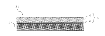
- FIG. 1 is a schematic cross-sectional view showing an example of the electrically peelable pressure-sensitive adhesive sheet of the present invention.
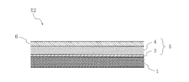
- FIG. 2 is a schematic cross-sectional view showing another example of the electrically peelable pressure-sensitive adhesive sheet of the present invention.
- FIG. 2 is a schematic cross-sectional view showing another example of the electrically peelable pressure-sensitive adhesive sheet of the present invention.
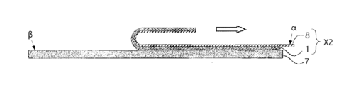
- FIG. 2 is a cross-sectional view showing an outline of the method for the 180° peel test in the examples.
- the electrically peelable pressure-sensitive adhesive sheet [Configuration of electrically peelable pressure-sensitive adhesive sheet]
- the electrically peelable pressure-sensitive adhesive sheet according to an embodiment of the present invention comprises a conductive substrate including a supporting substrate and a conductive layer containing a resin component; and an electrically peelable adhesive layer whose adhesive strength decreases upon application of a voltage; The electrically peelable pressure-sensitive adhesive layer and the conductive layer are in contact with each other.
- the electrically peelable adhesive sheet according to the embodiment of the present invention functions as follows: A voltage can be applied to the electrically peelable adhesive layer via the conductive substrate, which reduces the adhesive strength of the electrically peelable adhesive layer, allowing it to be easily peeled off.
- a metal layer is used as the conductive layer, and a coating layer is provided to protect the conductive layer (metal layer).
- the resin components in the coating layer hydrolyze, causing the coating layer to deteriorate, exposing the conductive layer and corroding the metal.
- the conductive layer peels off from the support substrate, and the sheet may no longer function as an electrically peelable adhesive sheet.
- deterioration of the coating layer can reduce the adhesive strength between the electrically peelable adhesive layer and the conductive substrate, causing peeling.
- the conductive substrate in the electrically peelable adhesive sheet according to the embodiment of the present invention includes a support substrate and a conductive layer containing a resin component.
- a conductive layer containing a resin component makes the conductive layer less likely to corrode even when exposed to high temperature and high humidity for a long period of time, and has the effect of preventing the conductive layer from peeling off from the support substrate when a voltage is applied.
- the inclusion of a resin component in the conductive layer improves the adhesion between the electrically peelable adhesive layer and the conductive substrate, and has the effect of preventing peeling off within the electrically peelable adhesive sheet exposed to high temperature and high humidity for a long period of time.
- the electrically peelable adhesive sheet according to the embodiment of the present invention does not require a coating layer for protecting the conductive layer, so that it is possible to prevent a decrease in the electrical peeling performance due to deterioration of the coating layer and a decrease in the adhesive strength between the electrically peelable adhesive layer and the conductive substrate.
- the conductive layer is provided by a means other than metal vapor deposition, and it is preferable that it does not include a metal layer.
- the electrically peelable adhesive sheet according to an embodiment of the present invention may have multiple conductive substrates and multiple electrically peelable adhesive layers, and may also have an adhesive layer, an intermediate layer, an undercoat layer, etc. in addition to the conductive substrate and the electrically peelable adhesive layer.
- the conductive substrate may have a plurality of supporting substrates and a plurality of conductive layers containing a resin component.
- the electrically peelable adhesive sheet according to the embodiment of the present invention may be, for example, in the form of a roll or in the form of a sheet.
- the term "electrically peelable adhesive sheet" also includes the meaning of "adhesive tape.” That is, the electrically peelable adhesive sheet according to the embodiment of the present invention may be an adhesive tape having a tape-like form.
- the electrically peelable pressure-sensitive adhesive sheet according to the embodiment of the present invention may be a single-sided electrically peelable pressure-sensitive adhesive sheet having a conductive substrate and an electrically peelable pressure-sensitive adhesive layer on only one side of the conductive substrate.
- the electrically peelable pressure-sensitive adhesive sheet according to an embodiment of the present invention may further comprise another pressure-sensitive adhesive layer that does not have electrical peeling properties, and may further comprise another pressure-sensitive adhesive layer on the surface of the electrically peelable pressure-sensitive adhesive sheet facing the supporting substrate.
- the electrically peelable pressure-sensitive adhesive sheet according to an embodiment of the present invention may be a double-sided electrically peelable pressure-sensitive adhesive sheet in which the conductive substrate has a conductive layer on both sides of a supporting substrate, and each conductive layer is provided with an electrically peelable pressure-sensitive adhesive layer.
- the electrically peelable adhesive sheet according to the embodiment of the present invention may have a release liner for the purpose of protecting the surface of the electrically peelable adhesive layer and other adhesive layers, but the release liner is not included in the electrically peelable adhesive sheet according to the embodiment of the present invention.
- the electrically peelable pressure-sensitive adhesive sheet according to the embodiment of the present invention further comprises another pressure-sensitive adhesive layer, It is also preferable that the electrically peelable pressure-sensitive adhesive sheet has the other pressure-sensitive adhesive layer formed on the surface of the supporting substrate opposite to the conductive layer.
- the electrically peelable pressure-sensitive adhesive sheet according to an embodiment of the present invention further comprises another pressure-sensitive adhesive layer, a second conductive layer containing a resin component, and a second other pressure-sensitive adhesive layer, the other pressure-sensitive adhesive layer is formed on the surface of the supporting substrate opposite to the conductive layer, the second conductive layer and a second other pressure-sensitive adhesive layer are formed in this order on a surface of the electrically peelable pressure-sensitive adhesive layer opposite to the conductive layer; It is also preferable that the electrically peelable pressure-sensitive adhesive sheet is one in which the electrically peelable pressure-sensitive adhesive layer and the second conductive layer are in contact with each other.
- the structure of the electrically peelable adhesive sheet according to the embodiment of the present invention is not particularly limited, but preferred examples include electrically peelable adhesive sheet X1 shown in FIG. 1, electrically peelable adhesive sheet X2 shown in FIG. 2, and electrically peelable adhesive sheet X3 shown in FIG. 3.
- the electrically peelable adhesive sheet X1 shown in FIG. 1 is an electrically peelable adhesive sheet having a layer structure of an electrically peelable adhesive layer 1 and a conductive substrate 5 (conductive layer 3 and supporting substrate 4).
- the electrically peelable adhesive sheet X2 shown in FIG. 2 is an electrically peelable adhesive sheet having a layer structure of other adhesive layer 6, conductive substrate 5 (support substrate 4 and conductive layer 3), and electrically peelable adhesive layer 1.
- the electrically peelable adhesive sheet X3 shown in FIG. 3 is an electrically peelable adhesive sheet having a layer structure including, in this order, other adhesive layer 6, conductive substrate 5 (support substrate 4, conductive layer 3), electrically peelable adhesive layer 1, conductive substrate 5 (conductive layer 3, support substrate 4), and other adhesive layer 6.
- the electrically peelable adhesive layer 1 in the electrically peelable adhesive sheet X3 shown in FIG. 3 is a double-sided electrically peelable adhesive sheet having, in this order, conductive layer 3, support substrate 4, and other adhesive layer 6 on both sides thereof.
- the conductive layer 3, which contains a resin component, is formed on the support substrate 4 and is in contact with the electrically peelable adhesive layer 1.
- the conductive layer 3 contains a resin component, which makes it less susceptible to corrosion even when exposed to high temperature and humidity for a long period of time, and also acts as a barrier to the ionic liquid contained in the electrically peelable adhesive layer 1 from penetrating into the conductive layer 3 when a voltage is applied, preventing the conductive layer 3 from peeling off from the support substrate 4.
- the conductive layer 3 which contains a resin component, is in contact with the electrically peelable adhesive layer 1, improving the adhesion between the electrically peelable adhesive layer 1 and the conductive layer 3, and preventing the interfacial adhesion between the electrically peelable adhesive layer and the conductive layer from decreasing due to thermal curing of the electrically peelable adhesive layer that has been exposed to a high temperature and high humidity environment for an extended period of time, resulting in peeling within the electrically peelable adhesive sheet.
- Examples of the resin component contained in the conductive layer 3 according to the embodiment of the present invention include a conductive polymer, a non-conductive polymer, a conductive oligomer, a non-conductive oligomer, a thermoplastic resin, and a thermosetting resin.
- the electrically peelable pressure-sensitive adhesive sheet is peeled off by applying a voltage to the electrically peelable pressure-sensitive adhesive layer, and therefore, from the viewpoint of electrical connection, it is preferable that the conductive layer contains a conductive polymer.
- Examples of conductive polymers according to the embodiments of the present invention include PEDOT/PSS (a composite of poly(3,4-ethylenedioxythiophene) (PEDOT) and polystyrenesulfonic acid (PSS)), polyacetylene-based polymers, polyaniline-based polymers, polypyrrole-based polymers, and the like.
- PEDOT/PSS a composite of poly(3,4-ethylenedioxythiophene) (PEDOT) and polystyrenesulfonic acid (PSS)
- polyacetylene-based polymers polyaniline-based polymers
- polypyrrole-based polymers polypyrrole-based polymers
- the content of the resin component in the conductive layer is preferably 70% by mass or more, more preferably 80% by mass or more, and even more preferably 90% by mass or more, relative to the total amount of the conductive layer (100% by mass).
- the upper limit may be 100% by mass or less, and may be 99.9% by mass or less, or 99.5% by mass or less.
- the conductive layer 3 according to the embodiment of the present invention may further contain various additives such as a crosslinking agent, a catalyst, a filler, a plasticizer, an antiaging agent, an antioxidant, a pigment (dye), a flame retardant, a solvent, a surfactant (leveling agent), a dispersant, a rust inhibitor, a corrosion inhibitor, etc.
- the total content of these components is not particularly limited as long as the effects of the present invention are exhibited, but is preferably 0.01 parts by mass or more and 20 parts by mass or less, more preferably 10 parts by mass or less, and even more preferably 5 parts by mass or less, relative to 100 parts by mass of the resin component.
- the conductive layer 3 according to the embodiment of the present invention may further contain a conductive filler, which will be described later.
- the resin component contained in the conductive layer 3 according to the embodiment of the present invention may be a non-conductive polymer.
- the conductive layer preferably contains a conductive filler or the like for the purpose of imparting conductivity.
- the conductive layer 3 according to the embodiment of the present invention may be formed from a conductive paste containing a resin component and a conductive filler.
- non-conductive polymers examples include acrylic resins, polyester resins, epoxy resins, urethane resins, phenolic resins, and epoxy resins. At least one selected from acrylic resins, urethane resins, epoxy resins, and polyester resins is preferred, and at least one selected from acrylic resins, urethane resins, and epoxy resins is more preferred.
- Acrylic resins include, for example, poly(meth)acrylic acid esters such as polymethyl methacrylate, methyl methacrylate-(meth)acrylic acid copolymers, methyl methacrylate-(meth)acrylic acid ester copolymers, methyl methacrylate-acrylic acid ester-(meth)acrylic acid copolymers, methyl (meth)acrylate-styrene copolymers (MS resins, etc.), and polymers having alicyclic hydrocarbon groups (for example, methyl methacrylate-cyclohexyl methacrylate copolymers, methyl methacrylate-norbornyl (meth)acrylate copolymers, etc.).
- poly(meth)acrylic acid esters such as polymethyl methacrylate, methyl methacrylate-(meth)acrylic acid copolymers, methyl methacrylate-(meth)acrylic acid ester copolymers, methyl methacrylate-acrylic acid ester
- (meth)acrylic means acrylic and/or methacrylic.
- Acrylic resins include those that have acrylic acid or a derivative thereof as a constituent monomer component, and those that have methacrylic acid or a derivative thereof as a constituent monomer component.
- urethane-based resins examples include oil-modified polyurethane resins, alkyd-based polyurethane resins, polyester-based polyurethane resins, and polyether-based urethane resins, with polyether-based urethane resins being preferred from the viewpoint of suppressing hydrolysis.
- Epoxy resins include, for example, crosslinked resins obtained by crosslinking epoxy groups present in epoxy group-containing monomers or epoxy group-containing prepolymers with a curing agent (such as a photopolymerization initiator or a thermal polymerization initiator).
- a curing agent such as a photopolymerization initiator or a thermal polymerization initiator.
- Specific examples of epoxy resins include bisphenol A type epoxy resins, bisphenol F type epoxy resins, cresol novolac type epoxy resins, alicyclic epoxy resins, and phenol novolac type epoxy resins.
- the non-conductive polymer may be crosslinkable.
- the non-conductive polymers may be used alone or in combination of two or more kinds.
- the content of the resin component in the conductive layer is preferably 0.1% by mass or more, and more preferably 1.0% by mass or more, relative to the total amount of the conductive layer (100% by mass).
- the upper limit is preferably 70% by mass or less, and more preferably 30% by mass or less.
- the conductive filler contained in the conductive layer according to the embodiment of the present invention is not particularly limited, and any commonly known or commonly used conductive filler can be used. Examples include particles made of metal, metal oxide, carbon, conductive polymer, metal-coated particles, etc., and among these, carbon particles or metal particles are preferably used because they are easy to handle. These can be used alone or in combination of multiple types.
- the shape of the conductive filler according to the embodiment of the present invention is not particularly limited, but examples include spherical, rod-like, flat, fibrous, hollow, angular, blocky, and aggregates thereof. Among these, it is preferable to use primary aggregates of spherical particles, since it is easy to control the proportion of conductive filler contained in the conductive layer.
- the average particle size of the conductive filler according to the embodiment of the present invention is preferably 0.001 ⁇ m or more, more preferably 0.05 ⁇ m or more, even more preferably 0.1 ⁇ m or more, even more preferably 0.2 ⁇ m or more, and particularly preferably 0.5 ⁇ m or more.
- the average particle size is preferably 30 ⁇ m or less, more preferably 20 ⁇ m or less, more preferably 10 ⁇ m or less, and even more preferably 5 ⁇ m or less.
- the average particle size of the conductive filler is preferably 0.001 to 30 ⁇ m, and more preferably 0.001 to 20 ⁇ m.
- the average particle size is within the above range in terms of maintaining good viscosity of the conductive paste and good dispersibility of the conductive filler.
- the conductive filler is carbon particles
- the average particle size is preferably 0.001 to 30 ⁇ m, more preferably 0.001 to 20 ⁇ m, and even more preferably 0.05 to 10 ⁇ m. If the particle size of the carbon particles is 0.001 ⁇ m or more, the amount of carbon particles added can be prevented from increasing, and the viscosity of the conductive paste can be prevented from increasing, resulting in excellent coatability. If the particle size of the carbon particles is 30 ⁇ m or less, a conductive path can be easily formed, and sufficient conductivity can be easily obtained.
- the average particle size is preferably 0.1 to 30 ⁇ m, more preferably 0.1 to 10 ⁇ m, and even more preferably 0.2 to 5 ⁇ m. If the particle size of the silver particles is 0.1 ⁇ m or more, the amount of silver particles added can be prevented from increasing, and the viscosity of the conductive paste can be prevented from increasing, resulting in excellent coatability. If the particle size of the silver particles is 30 ⁇ m or less, conductive paths can be easily formed, and sufficient conductivity can be easily obtained.
- the average particle size of the conductive filler refers to the particle size (50% median diameter) at which the cumulative particle size on a weight basis is 50% in the particle size distribution obtained by measurement based on a sieving method.
- Examples of the carbon particles include graphite, carbon black, acetylene black, ketjen black, carbon nanofibers, carbon nanotubes, graphene, fullerene, carbon nanocoils, carbon microcoils, carbon beads, carbon fibers, etc., and among these, carbon black is preferably used because of its low cost and ease of availability.
- the carbon black is not particularly limited, but for example, carbon black having a particle size of 50 nm or less, a specific surface area of 50 m 2 /100 g or more, and a DBP adsorption amount of 100 cm 3 /100 g or more is preferably used.
- the above metals may be, for example, metal particles of silver, copper, aluminum, nickel, iron, gold, stainless steel, and alloys thereof. From the viewpoint of electrical conductivity, silver, gold, copper, and aluminum are preferred, with silver being more preferred.
- the above metal oxides may, for example, be particles made of zinc oxide, indium oxide, tin oxide, titanium oxide, zirconium oxide, etc.
- the content of the conductive filler is preferably 0.1 parts by mass or more and 9900 parts by mass or less with respect to 100 parts by mass of the non-conductive polymer.
- the lower limit of the content of the conductive filler is preferably 3 parts by mass or more, more preferably 5 parts by mass or more, more preferably 10 parts by mass or more, more preferably 100 parts by mass or more, more preferably 200 parts by mass or more, more preferably 300 parts by mass or more, and even more preferably 400 parts by mass or more.
- the upper limit may be 4000 parts by mass or less, 2000 parts by mass or less, or 1000 parts by mass or less.
- the content of the conductive filler is within the above numerical range, it is preferable in terms of maintaining the viscosity of the conductive paste and the dispersibility of the conductive filler well.
- the lower limit of the content of the carbon particles is preferably 0.1 parts by mass or more, more preferably 5 parts by mass or more, more preferably 10 parts by mass or more, more preferably 25 parts by mass or more, more preferably 40 parts by mass or more, more preferably 100 parts by mass or more, and even more preferably 150 parts by mass or more, relative to 100 parts by mass of the non-conductive polymer.
- the upper limit is preferably 600 parts by mass or less, more preferably 400 parts by mass or less, more preferably 240 parts by mass or less, and even more preferably 200 parts by mass or less.
- the content of the carbon particles is preferably 0.1 parts by mass or more and 600 parts by mass or less, more preferably 25 parts by mass or more and 400 parts by mass or less, more preferably 40 parts by mass or more and 240 parts by mass or less, more preferably 100 parts by mass or more and 200 parts by mass or less, and even more preferably 150 parts by mass or more and 200 parts by mass or less, relative to 100 parts by mass of the non-conductive polymer. If the content of the carbon particles is 0.1 parts by mass or more, it is easy to form a conductive path and it is easy to obtain sufficient conductivity.
- the content of the carbon particles is 600 parts by mass or less, an increase in the viscosity of the conductive paste can be suppressed, and therefore, the coating property is excellent.
- the conductive filler is silver particles
- the lower limit of the content of the silver particles is preferably 50 parts by mass or more, more preferably 60 parts by mass or more, more preferably 70 parts by mass or more, more preferably 100 parts by mass or more, more preferably 150 parts by mass or more, and even more preferably 300 parts by mass or more, relative to 100 parts by mass of the non-conductive polymer.
- the upper limit is preferably 9900 parts by mass or less, may be 1900 parts by mass or less, may be 900 parts by mass or less, may be 500 parts by mass or less, may be 300 parts by mass or less, or may be 100 parts by mass or less.
- the content of the silver particles is preferably 50 parts by mass or more and 9900 parts by mass or less, more preferably 50 parts by mass or more and 1900 parts by mass or less, more preferably 70 parts by mass or more and 900 parts by mass or less, more preferably 70 parts by mass or more and 500 parts by mass or less, more preferably 70 parts by mass or more and 300 parts by mass or less, and even more preferably 70 parts by mass or more and 100 parts by mass or less.
- the content of silver particles is 50 parts by mass or more, a conductive path is easily formed and sufficient conductivity is easily obtained.
- the content of silver particles is 9,900 parts by mass or less, an increase in viscosity of the conductive paste is suppressed, and thus the coating property is excellent.
- the conductive layer (which may be a conductive paste) may contain the various additives described above in amounts within the range in which the effects of the present invention are achieved.
- crosslinking agent examples include an isocyanate-based crosslinking agent, a carbodiimide-based crosslinking agent, an epoxy-based crosslinking agent, a melamine-based crosslinking agent, a peroxide-based crosslinking agent, a urea-based crosslinking agent, a metal alkoxide-based crosslinking agent, a metal chelate-based crosslinking agent, a metal salt-based crosslinking agent, an oxazoline-based crosslinking agent, an aziridine-based crosslinking agent, and an amine-based crosslinking agent.
- isocyanate-based crosslinking agent examples include an isocyanate-based crosslinking agent, a carbodiimide-based crosslinking agent, an epoxy-based crosslinking agent, a melamine-based crosslinking agent, a peroxide-based crosslinking agent, a urea-based crosslinking agent, a metal alkoxide-based crosslinking agent, a metal chel
- isocyanate crosslinking agents include blocked isocyanate, toluene diisocyanate, and methylene bisphenyl isocyanate, etc.
- epoxy crosslinking agents include N,N,N',N'-tetraglycidyl-m-xylylene diamine, diglycidyl aniline, 1,3-bis(N,N-diglycidylaminomethyl)cyclohexane, and 1,6-hexanediol diglycidyl ether, etc.
- the content is preferably 0.01 parts by mass or more and 20 parts by mass or less relative to 100 parts by mass of the resin component.
- the upper limit is more preferably 10 parts by mass, and even more preferably 8 parts by mass.
- the lower limit is more preferably 1 part by mass, and even more preferably 2 parts by mass.
- the crosslinking agent may be used alone or in combination of two or more kinds.
- a crosslinking catalyst may be used to make the crosslinking reaction proceed more effectively.
- a tin-based catalyst particularly dioctyltin dilaurate
- the amount of the crosslinking catalyst used can be, for example, 0.0001 to 5 parts by mass per 100 parts by mass of the resin component.
- the thickness of the conductive layer 3 according to the embodiment of the present invention is preferably 0.001 ⁇ m or more and 1000 ⁇ m or less.
- the upper limit of the thickness is more preferably 500 ⁇ m, even more preferably 300 ⁇ m, even more preferably 100 ⁇ m, even more preferably 50 ⁇ m, even more preferably 10 ⁇ m, even more preferably 5 ⁇ m, even more preferably 2 ⁇ m, even more preferably 1 ⁇ m, even more preferably 0.5 ⁇ m, and the lower limit is more preferably 0.01 ⁇ m, even more preferably 0.02 ⁇ m, even more preferably 0.03 ⁇ m, even more preferably 0.04 ⁇ m, even more preferably 0.05 ⁇ m.
- the surface resistance value of the conductive layer according to the embodiment of the present invention may be 7000 ⁇ / ⁇ or less, and is preferably 5000 ⁇ / ⁇ or less. By having the surface resistance value of the conductive layer according to the embodiment of the present invention be 5000 ⁇ / ⁇ or less, excellent conductivity can be obtained.
- the lower limit of the surface resistance value of the conductive layer according to the embodiment of the present invention may be 0.001 ⁇ / ⁇ or more, 0.01 ⁇ / ⁇ or more, 0.1 ⁇ / ⁇ or more, 1 ⁇ / ⁇ or more, 10 ⁇ / ⁇ or more, or 100 ⁇ / ⁇ or more.
- the upper limit is preferably 3000 ⁇ / ⁇ or less, more preferably 2000 ⁇ / ⁇ or less, more preferably 1000 ⁇ / ⁇ or less, more preferably 500 ⁇ / ⁇ or less, more preferably 200 ⁇ / ⁇ or less, and even more preferably 150 ⁇ / ⁇ or less.
- the surface resistance value of the conductive layer according to the embodiment of the present invention can be measured by the method described in the examples.
- the support substrate 4 is not particularly limited, but may include paper-based substrates such as paper, fiber-based substrates such as cloth and nonwoven fabric, plastic-based substrates such as films and sheets made of various plastics (polyolefin-based resins such as polyethylene and polypropylene, polyester-based resins such as polyethylene terephthalate, acrylic resins such as polymethyl methacrylate, etc.), and laminates thereof.
- the substrate may have a single layer structure or a multi-layer structure.
- the substrate may be subjected to various treatments such as back surface treatment, antistatic treatment, and undercoat treatment, as necessary.
- the thickness of the support substrate 4 according to the embodiment of the present invention can be any thickness depending on the purpose. For example, a thickness of 10 ⁇ m or more and 1000 ⁇ m or less is preferable.
- the upper limit of the thickness is more preferably 500 ⁇ m, and even more preferably 300 ⁇ m, and the lower limit is more preferably 12 ⁇ m, and even more preferably 25 ⁇ m.
- the conductive substrate 5 according to the embodiment of the present invention is not particularly limited as long as it includes a support substrate 4 and a conductive layer 3 containing a resin component, but examples thereof include a substrate in which a conductive layer is formed on the surface of the support substrate 4, and examples thereof include a substrate in which a conductive layer-forming composition containing a resin component is applied to the surface of the support substrate exemplified above, and the conductive layer is formed by heating and/or curing.
- the thickness of the conductive substrate 5 according to the embodiment of the present invention can be any thickness depending on the purpose. For example, a thickness of 10 ⁇ m or more and 1000 ⁇ m or less is preferable.
- the upper limit of the thickness is more preferably 500 ⁇ m, and the lower limit is more preferably 12 ⁇ m, and even more preferably 25 ⁇ m.
- the electrically peelable pressure-sensitive adhesive sheet according to the embodiment of the present invention can be attached to a conductive material to form a bonded body.
- conductive materials include adherends such as metal-coated surfaces, and examples of metal-coated surfaces include surfaces made of metals mainly composed of aluminum, copper, iron, magnesium, tin, gold, silver, and lead, among which surfaces made of metals containing aluminum are preferred.
- adherends having metal-coated surfaces include sheets, parts, and plates made of metals mainly composed of aluminum, copper, iron, magnesium, tin, gold, silver, and lead.
- Adherends other than those having metal-coated surfaces include, but are not limited to, fiber sheets such as paper, cloth, and nonwoven fabric, and various plastic films and sheets.
- the electrically peelable pressure-sensitive adhesive layer 1 is a pressure-sensitive adhesive layer having the property of decreasing adhesive strength upon application of a voltage.
- the electrically peelable adhesive layer contains a polymer as an adhesive and an electrolyte.
- the electrolyte contained in the electrically peelable pressure-sensitive adhesive layer is a substance that can be ionized into anions and cations, and examples of such electrolytes include ionic liquids, alkali metal salts, alkaline earth metal salts, etc. From the viewpoint of realizing good electrical peelability in the electrically peelable pressure-sensitive adhesive layer, the electrolyte contained in the electrically peelable pressure-sensitive adhesive layer is preferably an ionic liquid.
- the ionic liquid is a salt that is liquid at room temperature (about 25° C.) and contains anions and cations. That is, the electrically peelable pressure-sensitive adhesive layer preferably contains a polymer and an ionic liquid.
- the electrically peelable pressure-sensitive adhesive layer 1 can be formed from a pressure-sensitive adhesive composition containing a polymer and an ionic liquid.
- the pressure-sensitive adhesive composition according to the embodiment of the present invention will be described below. In this specification, the adhesive strength when no voltage is applied is sometimes referred to as "initial adhesive strength.”
- a composition that contains components other than the ionic liquid among the components contained in the pressure-sensitive adhesive composition may be referred to as an "ionic liquid-free pressure-sensitive adhesive composition".
- a pressure-sensitive adhesive layer formed from an ionic liquid-free pressure-sensitive adhesive composition may be referred to as an "ionic liquid-free pressure-sensitive adhesive layer".
- the property of adhesive strength decreasing due to the application of voltage is called “electrical releasability," and a material having a large rate of decrease in adhesive strength due to the application of voltage is sometimes referred to as having "excellent electrical releasability.”
- the pressure-sensitive adhesive composition according to the embodiment of the present invention contains a polymer.
- the polymer is not particularly limited as long as it is a general organic polymer compound, and is, for example, a polymer or partial polymer of a monomer.
- the monomer may be one type of monomer or a mixture of two or more types of monomers.
- the partial polymer means a polymer in which at least a part of the monomer or monomer mixture is partially polymerized.
- the polymer in the present embodiment is not particularly limited as long as it is normally used as an adhesive and has adhesiveness, and examples thereof include acrylic polymers, rubber polymers, vinyl alkyl ether polymers, silicone polymers, polyester polymers, polyamide polymers, urethane polymers, fluorine polymers, and epoxy polymers, etc.
- the polymers may be used alone or in combination of two or more kinds. In order to increase the dielectric constant of the components other than the ionic liquid of the obtained electrically peelable pressure-sensitive adhesive layer and improve the electrical peelability, it is preferable that the dielectric constant of the polymer is large.
- the polymer in this embodiment contains at least one selected from the group consisting of polyester-based polymers and acrylic polymers having carboxyl groups and/or hydroxyl groups. Since polyester-based polymers have hydroxyl groups that are easily polarized at their terminals, and acrylic polymers having carboxyl groups and/or hydroxyl groups are easily polarized, a polymer with a relatively large dielectric constant can be obtained by using these polymers.
- the content of the polyester-based polymer and the acrylic polymer having carboxyl groups and/or hydroxyl groups in the polymer according to the embodiment of the present invention is preferably 60% by mass or more in total, more preferably 80% by mass or more.
- the polymer in this embodiment is preferably an acrylic polymer. That is, the pressure-sensitive adhesive composition according to the embodiment of the present invention is preferably an acrylic pressure-sensitive adhesive composition containing an acrylic polymer as a polymer.
- the acrylic polymer preferably contains a monomer unit derived from a (meth)acrylic acid alkyl ester (the following formula (1)) having an alkyl group having 1 to 14 carbon atoms.
- a monomer unit is suitable for obtaining a large initial adhesive strength.
- the number of carbon atoms in the alkyl group R b in the following formula (1) is preferably small, particularly preferably 8 or less, and more preferably 4 or less.
- CH 2 C(R a )COOR b (1) [In the formula (1), R a is a hydrogen atom or a methyl group, and R b is an alkyl group having 1 to 14 carbon atoms which may have a substituent]
- Examples of (meth)acrylic acid alkyl esters having an alkyl group having 1 to 14 carbon atoms include methyl (meth)acrylate, ethyl (meth)acrylate, propyl (meth)acrylate, isopropyl (meth)acrylate, n-butyl (meth)acrylate, sec-butyl (meth)acrylate, 1,3-dimethylbutyl acrylate, pentyl (meth)acrylate, isopentyl (meth)acrylate, hexyl (meth)acrylate, 2-ethylbutyl (meth)acrylate, acrylate, heptyl (meth)acrylate, n-octyl (meth)acrylate, isooctyl (meth)acrylate, 2-ethylhexyl (meth)acrylate, n-nonyl (meth)acrylate, isononyl (meth)acrylate, n-decyl
- (Meth)acrylic acid alkyl esters having an alkyl group with 1 to 14 carbon atoms can be used alone or in combination of two or more.
- the ratio of the (meth)acrylic acid alkyl ester having an alkyl group with 1 to 14 carbon atoms to the total monomer components (100% by mass) that make up the acrylic polymer is not particularly limited, but is preferably 70% by mass or more, more preferably 80% by mass or more, and even more preferably 85% by mass or more. If the ratio of the (meth)acrylic acid alkyl ester having an alkyl group with 1 to 14 carbon atoms is 70% by mass or more, it becomes easier to obtain a large initial adhesive strength.
- the acrylic polymer preferably contains a monomer unit derived from a polar group-containing monomer copolymerizable therewith, in addition to a monomer unit derived from a (meth)acrylic acid alkyl ester having an alkyl group with 1 to 14 carbon atoms.
- a monomer unit can provide crosslinking points and is suitable for obtaining a large initial adhesive strength.
- polar group-containing monomers examples include carboxyl group-containing monomers, hydroxyl group-containing monomers, cyano group-containing monomers, vinyl group-containing monomers, aromatic vinyl monomers, amide group-containing monomers, imide group-containing monomers, amino group-containing monomers, epoxy group-containing monomers, vinyl ether monomers, N-acryloylmorpholine, sulfo group-containing monomers, phosphate group-containing monomers, and acid anhydride group-containing monomers.
- carboxyl group-containing monomers, hydroxyl group-containing monomers, and amide group-containing monomers are preferred from the viewpoint of excellent cohesiveness, and carboxyl group-containing monomers are particularly preferred.
- Carboxyl group-containing monomers are particularly suitable for obtaining large initial adhesive strength.
- Polar group-containing monomers can be used alone or in combination of two or more.
- Carboxyl group-containing monomers include, for example, acrylic acid, methacrylic acid, carboxyethyl (meth)acrylate, carboxypentyl (meth)acrylate, itaconic acid, maleic acid, fumaric acid, crotonic acid, and isocrotonic acid. Acrylic acid is particularly preferred. Carboxyl group-containing monomers can be used alone or in combination of two or more.
- hydroxyl group-containing monomers examples include 2-hydroxyethyl (meth)acrylate, 2-hydroxypropyl (meth)acrylate, 4-hydroxybutyl (meth)acrylate, 6-hydroxyhexyl (meth)acrylate, 8-hydroxyoctyl (meth)acrylate, 10-hydroxydecyl (meth)acrylate, 12-hydroxylauryl (meth)acrylate, (4-hydroxymethylcyclohexyl)methyl (meth)acrylate, N-methylol (meth)acrylamide, vinyl alcohol, allyl alcohol, 2-hydroxyethyl vinyl ether, 4-hydroxybutyl vinyl ether, and diethylene glycol monovinyl ether.
- 2-hydroxyethyl (meth)acrylate and 4-hydroxybutyl (meth)acrylate are preferred.
- the hydroxyl group-containing monomers can be used alone or in combination of two or more.
- amide group-containing monomers examples include acrylamide, methacrylamide, N-vinylpyrrolidone, N,N-dimethylacrylamide, N,N-dimethylmethacrylamide, N,N-diethylacrylamide, N,N-diethylmethacrylamide, N,N'-methylenebisacrylamide, N,N-dimethylaminopropylacrylamide, N,N-dimethylaminopropylmethacrylamide, and diacetoneacrylamide.
- the amide group-containing monomers can be used alone or in combination of two or more.
- Cyano group-containing monomers include, for example, acrylonitrile and methacrylonitrile.
- vinyl group-containing monomers examples include vinyl esters such as vinyl acetate, vinyl propionate, and vinyl laurate, with vinyl acetate being particularly preferred.
- Aromatic vinyl monomers include, for example, styrene, chlorostyrene, chloromethylstyrene, ⁇ -methylstyrene, and other substituted styrenes.
- imide group-containing monomers examples include cyclohexylmaleimide, isopropylmaleimide, N-cyclohexylmaleimide, and itaconimide.
- amino group-containing monomers examples include aminoethyl (meth)acrylate, N,N-dimethylaminoethyl (meth)acrylate, and N,N-dimethylaminopropyl (meth)acrylate.
- epoxy group-containing monomers examples include glycidyl (meth)acrylate, methyl glycidyl (meth)acrylate, and allyl glycidyl ether.
- vinyl ether monomers examples include methyl vinyl ether, ethyl vinyl ether, and isobutyl vinyl ether.
- the ratio of the polar group-containing monomer to the total monomer components (100% by mass) constituting the acrylic polymer is preferably 0.1% by mass or more and 35% by mass or less.
- the upper limit of the polar group-containing monomer ratio is more preferably 25% by mass, even more preferably 20% by mass, and the lower limit is more preferably 0.5% by mass, even more preferably 1% by mass, and particularly preferably 2% by mass.
- the ratio of the polar group-containing monomer is 30% by mass or less, it is easy to prevent the electrically peelable adhesive layer from excessively adhering to the adherend and causing heavy peeling.
- the ratio is 2% by mass or more and 20% by mass or less, it is easy to achieve both releasability to the adherend and adhesion between the electrically peelable adhesive layer and the conductive layer.
- the monomer components constituting the acrylic polymer may also contain polyfunctional monomers to introduce a crosslinked structure into the acrylic polymer, making it easier to obtain the required cohesive strength.
- polyfunctional monomers examples include ethylene glycol di(meth)acrylate, diethylene glycol di(meth)acrylate, tetraethylene glycol di(meth)acrylate, neopentyl glycol di(meth)acrylate, 1,6-hexanediol di(meth)acrylate, trimethylolpropane tri(meth)acrylate, pentaerythritol tri(meth)acrylate, dipentaerythritol hexa(meth)acrylate, divinylbenzene, and N,N'-methylenebisacrylamide.
- the polyfunctional monomers can be used alone or in combination of two or more.
- the content of the polyfunctional monomer relative to the total monomer components (100% by mass) constituting the acrylic polymer is preferably 0.1% by mass or more and 15% by mass or less.
- the upper limit of the polyfunctional monomer content is more preferably 10% by mass, and the lower limit is more preferably 3% by mass. If the content of the polyfunctional monomer is 0.1% by mass or more, the flexibility and adhesiveness of the electrically peelable pressure-sensitive adhesive layer are more likely to be improved, which is preferable. If the content of the polyfunctional monomer is 15% by mass or less, the cohesive force is not too high, and it is easier to obtain appropriate adhesiveness.
- Polyester-based polymers are typically polymers that have a structure formed by condensation of polycarboxylic acids such as dicarboxylic acids or their derivatives (hereinafter also referred to as “polycarboxylic acid monomers”) with polyhydric alcohols such as diols or their derivatives (hereinafter referred to as “polyhydric alcohol monomers").
- polycarboxylic acids such as dicarboxylic acids or their derivatives
- polyhydric alcohol monomers such as diols or their derivatives
- the polyvalent carboxylic acid monomer is not particularly limited, but examples thereof that can be used include adipic acid, azelaic acid, dimer acid, sebacic acid, 1,4-cyclohexanedicarboxylic acid, 1,3-cyclohexanedicarboxylic acid, 1,2-cyclohexanedicarboxylic acid, 4-methyl-1,2-cyclohexanedicarboxylic acid, dodecenylsuccinic anhydride, fumaric acid, succinic acid, dodecanedioic acid, hexahydrophthalic anhydride, tetrahydrophthalic anhydride, maleic acid, maleic anhydride, itaconic acid, citraconic acid, and derivatives thereof.
- the polyvalent carboxylic acid monomers may be used alone or in combination of two or more kinds.
- the polyhydric alcohol monomer is not particularly limited, but for example, ethylene glycol, 1,2-propylene glycol, 1,3-propanediol, 2-methyl-1,3-propanediol, 1,2-butanediol, 1,3-butanediol, 1,4-butanediol, 1,5-pentanediol, 1,6-hexanediol, 3-methyl-1,5-pentanediol, neopentyl glycol, diethylene glycol, dipropylene glycol, 2,2,4-trimethyl-1,5-pentanediol, 2-ethyl-2-butylpropanediol, 1,9-nonanediol, 2-methyloctanediol, 1,10-decanediol, and derivatives thereof can be used.
- the polyhydric alcohol monomers can be used alone or in combination of two or more kinds.
- the polymer according to the embodiment of the present invention may also contain an ionic polymer.
- the ionic polymer is a polymer having an ionic functional group.
- the content of the ionic polymer is preferably 0.05 parts by mass or more and 2 parts by mass or less per 100 parts by mass of the polymer.
- the polymer can be obtained by (co)polymerizing the monomer components.
- the polymerization method is not particularly limited, but examples include solution polymerization, emulsion polymerization, bulk polymerization, suspension polymerization, and photopolymerization (active energy ray polymerization). In particular, from the viewpoint of cost and productivity, the solution polymerization method is preferable.
- the polymer is copolymerized, it may be any of a random copolymer, a block copolymer, an alternating copolymer, a graft copolymer, etc.
- solution polymerization method examples include a method in which monomer components, a polymerization initiator, etc. are dissolved in a solvent and polymerized by heating to obtain a polymer solution containing the polymer.
- solvents can be used as the solvent for the solution polymerization method.
- solvents include organic solvents such as aromatic hydrocarbons such as toluene, benzene, and xylene; esters such as ethyl acetate and n-butyl acetate; aliphatic hydrocarbons such as n-hexane and n-heptane; alicyclic hydrocarbons such as cyclohexane and methylcyclohexane; and ketones such as methyl ethyl ketone and methyl isobutyl ketone.
- Solvents can be used alone or in combination of two or more kinds.
- the amount of the solvent used is not particularly limited, but is preferably 10 parts by mass or more and 1,000 parts by mass or less relative to the total monomer components (100 parts by mass) that make up the polymer.
- the upper limit of the amount of the solvent used is more preferably 500 parts by mass, and the lower limit is more preferably 50 parts by mass.
- Polymerization initiators used in the solution polymerization method include, but are not limited to, peroxide-based polymerization initiators, azo-based polymerization initiators, etc.
- Peroxide-based polymerization initiators include, but are not limited to, peroxycarbonates, ketone peroxides, peroxyketals, hydroperoxides, dialkyl peroxides, diacyl peroxides, and peroxyesters, and more specifically, benzoyl peroxide, t-butyl hydroperoxide, di-t-butyl peroxide, t-butyl peroxybenzoate, dicumyl peroxide, 1,1-bis(t-butylperoxy)-3,3,5-trimethylcyclohexane, and 1,1-bis(t-butylperoxy)cyclododecane, etc.
- the azo-based polymerization initiator is not particularly limited, but examples thereof include 2,2'-azobisisobutyronitrile, 2,2'-azobis-2-methylbutyronitrile, 2,2'-azobis(2,4-dimethylvaleronitrile), 2,2'-azobis(2-methylpropionic acid)dimethyl, 2,2'-azobis(4-methoxy-2,4-dimethylvaleronitrile), 1,1'-azobis(cyclohexane-1-carbonitrile), 2,2'-azobis(2,4,4-trimethylpentane), 4,4'-azobis -4-cyanovaleric acid, 2,2'-azobis(2-amidinopropane) dihydrochloride, 2,2'-azobis[2-(5-methyl-2-imidazolin-2-yl)propane] dihydrochloride, 2,2'-azobis(2-methylpropionamidine) disulfate, 2,2'-azobis(N,N'-dimethyleneisobut
- the amount of polymerization initiator used is not particularly limited, but is preferably 0.01 parts by mass or more and 5 parts by mass or less relative to the total monomer components (100 parts by mass) that make up the polymer.
- the upper limit of the amount of polymerization initiator used is more preferably 3 parts by mass, and the lower limit is more preferably 0.05 parts by mass.
- the heating temperature when polymerizing by heating is not particularly limited, but is, for example, 50°C or higher and 80°C or lower.
- the heating time is not particularly limited, but is, for example, 1 hour or higher and 24 hours or lower.
- the weight-average molecular weight of the polymer is not particularly limited, but is preferably 100,000 or more and 5 million or less.
- the upper limit of the weight-average molecular weight is more preferably 4 million, and even more preferably 3 million, and the lower limit is more preferably 200,000, and even more preferably 300,000. If the weight-average molecular weight is 100,000 or more, the cohesive force is small, and the problem of adhesive residue remaining on the adherend surface after the electrically peelable adhesive layer is peeled off can be effectively suppressed. Furthermore, if the weight-average molecular weight is 5 million or less, the problem of insufficient wettability on the adherend surface after the electrically peelable adhesive layer is peeled off can be effectively suppressed.
- the weight average molecular weight is obtained by measurement by gel permeation chromatography (GPC). More specifically, for example, it can be measured using a GPC measurement device under the trade name "HLC-8220GPC” (manufactured by Tosoh Corporation) under the following conditions, and calculated in terms of standard polystyrene.
- GPC gel permeation chromatography
- the glass transition temperature (Tg) of the polymer is not particularly limited, but is preferably 0°C or lower since this prevents a decrease in the initial adhesive strength, more preferably -10°C or lower, and even more preferably -20°C or lower. Furthermore, it is particularly preferable for the glass transition temperature (Tg) to be -40°C or lower since the rate of decrease in adhesive strength due to the application of voltage is particularly large, and is most preferably -50°C or lower.
- the above formula (Y) is a calculation formula when the polymer is composed of n types of monomer components, namely, monomer 1, monomer 2, . . . , monomer n.
- the glass transition temperature when a homopolymer is formed means the glass transition temperature of a homopolymer of the monomer, and means the glass transition temperature (Tg) of a polymer formed using only a certain monomer (sometimes referred to as "monomer X") as a monomer component.
- Tg glass transition temperature
- monomer X a monomer formed using only a certain monomer
- the homopolymer solution is then cast onto a release liner and dried to produce a test sample (homopolymer sheet) with a thickness of about 2 mm.
- a test sample homopolymer sheet
- Approximately 1 to 2 mg of the test sample is weighed into an aluminum open cell, and the reversing heat flow (specific heat component) behavior of the homopolymer is obtained using a temperature-modulated DSC (product name "Q-2000" manufactured by TA Instruments) at a heating rate of 5°C/min under a nitrogen atmosphere of 50 ml/min.
- the glass transition temperature (Tg) of the homopolymer is determined as the temperature at the point where a straight line equidistant in the vertical direction from a straight line extending the low-temperature side baseline and the high-temperature side baseline of the obtained reversing heat flow intersects with the curve of the stepwise change in the glass transition.
- the polymer content in the adhesive composition according to the embodiment of the present invention is preferably 50% by mass or more and 99.9% by mass or less, based on the total amount of the adhesive composition (100% by mass), with the upper limit being more preferably 99.5% by mass, and even more preferably 99% by mass, and the lower limit being more preferably 60% by mass, and even more preferably 70% by mass.
- the ionic liquid in the present embodiment is not particularly limited as long as it is a molten salt (room temperature molten salt) composed of a pair of anion and cation and is liquid at 25° C.
- molten salt room temperature molten salt
- anions and cations are given below, but among the ionic substances obtained by combining these, those that are liquid at 25° C. are ionic liquids, and those that are solid at 25° C. are not ionic liquids but ionic solids described below.
- Examples of anions of ionic liquids include ( FSO2 ) 2N- , ( CF3SO2 ) 2N- , (CF3CF2SO2 ) 2N- , ( CF3SO2 ) 3C- , Br- , AlCl4- , Al2Cl7- , NO3- , BF4- , PF6- , CH3COO- , CF3COO- , CF3CF2CF2COO- , CF3SO3- , CF3 ( CF2 ) 3SO3- , AsF6- , SbF6- , and F ( HF ) n- .
- the anions of sulfonylimide compounds such as (FSO 2 ) 2 N ⁇ [bis(fluorosulfonyl)imide anion] and (CF 3 SO 2 ) 2 N ⁇ [bis(trifluoromethanesulfonyl)imide anion] are preferred as they are chemically stable and suitable for improving electrical peeling properties.
- the anion of the ionic liquid is preferably at least one selected from the group consisting of bis(fluorosulfonyl)imide anion and bis(trifluoromethanesulfonyl)imide anion.
- the cation in the ionic liquid is preferably at least one selected from the group consisting of nitrogen-containing onium cations, sulfur-containing onium cations, and phosphorus-containing onium cations, as these are chemically stable and suitable for improving electrical peelability, and imidazolium-based, ammonium-based, pyrrolidinium-based, and pyridinium-based cations are more preferred.
- imidazolium cations include 1-methylimidazolium cation, 1-ethyl-3-methylimidazolium cation, 1-propyl-3-methylimidazolium cation, 1-butyl-3-methylimidazolium cation, 1-pentyl-3-methylimidazolium cation, 1-hexyl-3-methylimidazolium cation, 1-heptyl-3-methylimidazolium cation, 1-octyl-3-methylimidazolium cation, 1-nonyl-3-methylimidazolium cation, 1-undecyl-3-methylimidazolium cation, 1-dodecyl-3-methylimidazolium imidazolium cation, 1-tridecyl-3-methylimidazolium cation, 1-tetradecyl-3-methylimidazolium cation, 1-pentadecyl-3-methylimidazolium cation
- pyridinium cations include 1-butylpyridinium cation, 1-hexylpyridinium cation, 1-butyl-3-methylpyridinium cation, 1-butyl-4-methylpyridinium cation, and 1-octyl-4-methylpyridinium cation.
- pyrrolidinium cations include 1-ethyl-1-methylpyrrolidinium cation and 1-butyl-1-methylpyrrolidinium cation.
- ammonium cations include tetraethylammonium cation, tetrabutylammonium cation, methyltrioctylammonium cation, tetradecyltrihexylammonium cation, glycidyltrimethylammonium cation, and trimethylaminoethyl acrylate cation.
- a constituent cation having a molecular weight of 160 or less for the ionic liquid, and an ionic liquid containing the above-mentioned (FSO 2 ) 2 N ⁇ [bis(fluorosulfonyl)imide anion] or (CF 3 SO 2 ) 2 N ⁇ [bis(trifluoromethanesulfonyl)imide anion] and a cation having a molecular weight of 160 or less is particularly preferable.
- Examples of the cation having a molecular weight of 160 or less include 1-methylimidazolium cation, 1-ethyl-3-methylimidazolium cation, 1-propyl-3-methylimidazolium cation, 1-butyl-3-methylimidazolium cation, 1-pentyl-3-methylimidazolium cation, 1-butylpyridinium cation, 1-hexylpyridinium cation, 1-butyl-3-methylpyridinium cation, 1-butyl-4-methylpyridinium cation, 1-ethyl-1-methylpyrrolidinium cation, 1-butyl-1-methylpyrrolidinium cation, tetraethylammonium cation, glycidyltrimethylammonium cation, and trimethylaminoethyl acrylate cation.
- the cations of the ionic liquid are preferably those represented by the following formulas (2-A) to (2-D).
- R 1 represents a hydrocarbon group having 4 to 10 carbon atoms (preferably a hydrocarbon group having 4 to 8 carbon atoms, more preferably a hydrocarbon group having 4 to 6 carbon atoms) which may contain a heteroatom
- R 2 and R 3 are the same or different and represent a hydrogen atom or a hydrocarbon group having 1 to 12 carbon atoms (preferably a hydrocarbon group having 1 to 8 carbon atoms, more preferably a hydrocarbon group having 2 to 6 carbon atoms, even more preferably a hydrocarbon group having 2 to 4 carbon atoms) which may contain a heteroatom, provided that when a nitrogen atom forms a double bond with an adjacent carbon atom, R 3 does not exist.
- R 4 represents a hydrocarbon group having 2 to 10 carbon atoms (preferably a hydrocarbon group having 2 to 8 carbon atoms, more preferably a hydrocarbon group having 2 to 6 carbon atoms) which may contain a heteroatom
- R 5 , R 6 , and R 7 are the same or different and represent a hydrogen atom or a hydrocarbon group having 1 to 12 carbon atoms (preferably a hydrocarbon group having 1 to 8 carbon atoms, more preferably a hydrocarbon group having 2 to 6 carbon atoms, and even more preferably a hydrocarbon group having 2 to 4 carbon atoms) which may contain a heteroatom.
- R 8 represents a hydrocarbon group having 2 to 10 carbon atoms (preferably a hydrocarbon group having 2 to 8 carbon atoms, more preferably a hydrocarbon group having 2 to 6 carbon atoms) which may contain a heteroatom
- R 9 , R 10 , and R 11 are the same or different and represent a hydrogen atom or a hydrocarbon group having 1 to 16 carbon atoms (preferably a hydrocarbon group having 1 to 10 carbon atoms, more preferably a hydrocarbon group having 1 to 8 carbon atoms) which may contain a heteroatom.
- X represents a nitrogen, sulfur, or phosphorus atom
- R 12 , R 13 , R 14 , and R 15 are the same or different and represent a hydrocarbon group having 1 to 16 carbon atoms (preferably a hydrocarbon group having 1 to 14 carbon atoms, more preferably a hydrocarbon group having 1 to 10 carbon atoms, even more preferably a hydrocarbon group having 1 to 8 carbon atoms, and particularly preferably a hydrocarbon group having 1 to 6 carbon atoms), which may contain a heteroatom, provided that when X is a sulfur atom, R 12 does not exist.
- the molecular weight of the cation in the ionic liquid is, for example, 500 or less, preferably 400 or less, more preferably 300 or less, even more preferably 250 or less, particularly preferably 200 or less, and most preferably 160 or less. It is usually 50 or more. It is considered that the cation in the ionic liquid has the property of migrating to the cathode side in the electrically peelable adhesive layer when a voltage is applied, and being biased toward the interface between the electrically peelable adhesive layer and the adherend. For this reason, in the present invention, the adhesive strength during voltage application decreases compared to the initial adhesive strength, and electro-peeling properties occur.
- Cations with a small molecular weight are suitable for making it easier for the cation to migrate to the cathode side in the electrically peelable adhesive layer, and for increasing the rate of decrease in adhesive strength when a voltage is applied.
- ionic liquids include, for example, "ELEXEL AS-110,” “ELEXEL MP-442,” “ELEXEL IL-210,” “ELEXEL MP-471,” “ELEXEL MP-456,” and “ELEXEL AS-804" manufactured by Daiichi Kogyo Seiyaku Co., Ltd., "HMI-FSI” manufactured by Mitsubishi Materials Corporation, and "CIL-312” and “CIL-313” manufactured by Nippon Carlit Co., Ltd.
- the ionic conductivity is preferably 0.1 mS/cm or more and 20 mS/cm or less.
- the upper limit of the ionic conductivity is more preferably 18 mS/cm, and the lower limit is more preferably 0.3 mS/cm, more preferably 0.5 mS/cm, more preferably 1 mS/cm, more preferably 5 mS/cm, more preferably 8 mS/cm, and even more preferably 10 mS/cm.
- the ionic conductivity can be measured by the AC impedance method using, for example, a Solartron 1260 frequency response analyzer.
- the content (mixture amount) of ionic liquid in the adhesive composition according to an embodiment of the present invention is preferably 0.5 parts by mass or more relative to 100 parts by mass of polymer in terms of reducing adhesive strength during voltage application, and is preferably 30 parts by mass or less in terms of increasing initial adhesive strength. From the same viewpoint, it is more preferably 20 parts by mass or less, even more preferably 15 parts by mass or less, particularly preferably 10 parts by mass or less, and most preferably 5 parts by mass or less. It is also more preferably 0.6 parts by mass or more, even more preferably 0.8 parts by mass or more, particularly preferably 1.0 part by mass or more, and most preferably 1.5 parts by mass or more.
- the pressure-sensitive adhesive composition according to the embodiment of the present invention may contain one or more components other than the polymer and the ionic liquid (hereinafter, sometimes referred to as "other components"), as necessary, within a range that does not impair the effects of the present invention.
- other components other components that may be contained in the pressure-sensitive adhesive composition according to the embodiment of the present invention will be described.
- the adhesive composition according to the embodiment of the present invention may contain an ionic additive.
- an ionic additive for example, an ionic solid can be used.
- the ionic solid is an ionic substance that is solid at 25°C.
- a solid ionic substance obtained by combining an anion and a cation as exemplified in the section explaining the ionic liquid above can be used.
- the content of the ionic solid is preferably 0.5 parts by mass or more and 10 parts by mass or less per 100 parts by mass of the polymer.
- the adhesive composition according to the embodiment of the present invention may contain a crosslinking agent as necessary for the purpose of improving creep and shear properties by crosslinking the polymer.
- crosslinking agents include isocyanate-based crosslinking agents, carbodiimide-based crosslinking agents, epoxy-based crosslinking agents, melamine-based crosslinking agents, peroxide-based crosslinking agents, urea-based crosslinking agents, metal alkoxide-based crosslinking agents, metal chelate-based crosslinking agents, metal salt-based crosslinking agents, oxazoline-based crosslinking agents, aziridine-based crosslinking agents, and amine-based crosslinking agents.
- isocyanate-based crosslinking agents examples include toluene diisocyanate and methylene bisphenyl isocyanate.
- epoxy-based crosslinking agents include N,N,N',N'-tetraglycidyl-m-xylylene diamine, diglycidyl aniline, 1,3-bis(N,N-diglycidylaminomethyl)cyclohexane, and 1,6-hexanediol diglycidyl ether.
- the content is preferably 0.1 parts by mass or more and 50 parts by mass or less per 100 parts by mass of the polymer.
- the crosslinking agent may be used alone or in combination of two or more kinds.
- the adhesive composition according to the embodiment of the present invention may contain polyethylene glycol as necessary for the purpose of aiding the movement of the ionic liquid when a voltage is applied.
- the polyethylene glycol may have a number average molecular weight of 200 to 6000.
- the content is preferably 0.1 parts by mass or more and 30 parts by mass or less per 100 parts by mass of the polymer.
- the adhesive composition according to the embodiment of the present invention may contain a conductive filler as necessary for the purpose of imparting electrical conductivity to the adhesive composition.
- a conductive filler there are no particular limitations on the conductive filler, and any commonly known or commonly used conductive filler may be used, such as graphite, carbon black, carbon fiber, or metal powder such as silver or copper.
- the content is preferably 0.1 parts by mass or more and 200 parts by mass or less per 100 parts by mass of the polymer.
- the adhesive composition according to the embodiment of the present invention may also contain various additives such as fillers, plasticizers, antioxidants, antioxidants, pigments (dyes), flame retardants, solvents, surfactants (leveling agents), rust inhibitors, adhesion-imparting resins, corrosion inhibitors, and antistatic agents.
- the total content of these components is not particularly limited as long as the effects of the present invention are achieved, but is preferably 0.01 parts by mass or more and 20 parts by mass or less, more preferably 10 parts by mass or less, and even more preferably 5 parts by mass or less, per 100 parts by mass of the polymer.
- the filler examples include silica, iron oxide, zinc oxide, aluminum oxide, titanium oxide, barium oxide, magnesium oxide, calcium carbonate, magnesium carbonate, zinc carbonate, pyrophyllite clay, kaolin clay, and calcined clay.
- the plasticizer may be a known, commonly used plasticizer used in general resin compositions, etc., and examples of the plasticizer that may be used include oils such as paraffin oil and process oil, liquid rubbers such as liquid polyisoprene, liquid polybutadiene, and liquid ethylene-propylene rubber, tetrahydrophthalic acid, azelaic acid, benzoic acid, phthalic acid, trimellitic acid, pyromellitic acid, adipic acid, sebacic acid, fumaric acid, maleic acid, itaconic acid, citric acid, and derivatives thereof, dioctyl phthalate (DOP), dibutyl phthalate (DBP), dioctyl adipate, diisononyl a
- antioxidants examples include hindered phenol compounds, and aliphatic and aromatic hindered amine compounds.
- antioxidants examples include butylhydroxytoluene (BHT) and butylhydroxyanisole (BHA).
- pigments include inorganic pigments such as titanium dioxide, zinc oxide, ultramarine, red iron oxide, lithopone, lead, cadmium, iron, cobalt, aluminum, hydrochloride, and sulfate, azo pigments, and organic pigments such as copper phthalocyanine pigments.
- rust inhibitor examples include zinc phosphate, tannic acid derivatives, phosphoric esters, basic sulfonates, and various rust inhibitor pigments.
- adhesion promoters include titanium coupling agents and zirconium coupling agents.
- antistatic agent generally, quaternary ammonium salts, or hydrophilic compounds such as polyglycolic acid and ethylene oxide derivatives, etc. are mentioned.
- tackifier resins include rosin-based tackifier resins, terpene-based tackifier resins, phenol-based tackifier resins, hydrocarbon-based tackifier resins, ketone-based tackifier resins, polyamide-based tackifier resins, epoxy-based tackifier resins, and elastomer-based tackifier resins.
- the tackifier resins may be used alone or in combination of two or more.
- corrosion inhibitors include carbodiimide compounds, adsorption inhibitors, and chelate-forming metal deactivators. For example, those described in JP 2019-059908 A can be used.
- the adhesive strength of the electrically peelable pressure-sensitive adhesive layer according to the embodiment of the present invention can be evaluated by various methods, for example, the 180° peel test described in the Examples section.
- the electrically peelable adhesive layer according to an embodiment of the present invention is formed into an electrically peelable adhesive sheet as described in the Examples section, and after long-term storage under high temperature and high humidity conditions, the initial adhesive strength (adhesive strength when no voltage is applied) measured by a 180° peel test is preferably 2.0 N/cm or more, more preferably 2.5 N/cm or more, and most preferably 3.0 N/cm or more. If the initial adhesive strength is 3.0 N/cm or more, the adhesion to the adherend is sufficient and the adherend is unlikely to peel off or shift.
- the electrically peelable adhesive layer according to an embodiment of the present invention is formed into an electrically peelable adhesive sheet as described in the Examples section, and after long-term storage under high temperature and high humidity conditions, the electrical peel strength measured by applying a voltage and then carrying out a 180° peel test is preferably, for example, 3.0 N/cm or less, and more preferably 2.0 N/cm or less.
- the applied voltage is preferably 1 V or more, more preferably 3 V or more, more preferably 5 V or more, more preferably 6 V or more, and even more preferably 10 V or more. Also, it is preferably 500 V or less, more preferably 300 V or less, even more preferably 100 V or less, and particularly preferably 50 V or less.
- the voltage application time is preferably 300 seconds or less, more preferably 180 seconds or less, even more preferably 120 seconds or less, even more preferably 60 seconds or less, and particularly preferably 30 seconds or less. In such a case, the workability is excellent. In addition, the shorter the application time, the better, but it is usually 1 second or more.
- the adhesive composition according to the embodiment of the present invention is not particularly limited, but can be produced by appropriately stirring and mixing a polymer, an ionic liquid, and additives such as a crosslinking agent, polyethylene glycol, and a conductive filler, which are added as necessary.
- the thickness of the electrically peelable adhesive layer 1 is preferably 1 ⁇ m or more and 1000 ⁇ m or less.
- the upper limit of the thickness of the electrically peelable adhesive layer 1 is more preferably 500 ⁇ m, even more preferably 300 ⁇ m, even more preferably 200 ⁇ m, even more preferably 150 ⁇ m, even more preferably 100 ⁇ m, even more preferably 80 ⁇ m, even more preferably 70 ⁇ m, even more preferably 60 ⁇ m, even more preferably 50 ⁇ m, and the lower limit is more preferably 5 ⁇ m, even more preferably 10 ⁇ m, even more preferably 20 ⁇ m, even more preferably 30 ⁇ m.
- the thickness of the electrically peelable adhesive sheet according to the embodiment of the present invention is preferably 20 ⁇ m or more and 3000 ⁇ m or less.
- the upper limit of the thickness is more preferably 1000 ⁇ m, even more preferably 500 ⁇ m, even more preferably 300 ⁇ m, even more preferably 250 ⁇ m, even more preferably 200 ⁇ m, even more preferably 150 ⁇ m, even more preferably 100 ⁇ m, and the lower limit is more preferably 30 ⁇ m, even more preferably 50 ⁇ m.
- the thickness of the electrically peelable adhesive sheet is preferably 20 ⁇ m or more and 2000 ⁇ m or less.
- the upper limit of the thickness is more preferably 1000 ⁇ m, even more preferably 500 ⁇ m, even more preferably 300 ⁇ m, even more preferably 250 ⁇ m, even more preferably 200 ⁇ m, even more preferably 150 ⁇ m, and the lower limit is more preferably 30 ⁇ m, even more preferably 50 ⁇ m, even more preferably 100 ⁇ m.
- the thickness of the electrically peelable adhesive sheet is preferably 50 ⁇ m or more and 3000 ⁇ m or less.
- the upper limit of the thickness is more preferably 1000 ⁇ m, and even more preferably 500 ⁇ m, and the lower limit is more preferably 50 ⁇ m, and even more preferably 100 ⁇ m, and even more preferably 200 ⁇ m.
- the electrically peelable adhesive layer of the electrically peelable adhesive sheet according to the embodiment of the present invention, and the surface of the adhesive layer when it has other adhesive layers, may be protected by a release liner.
- the release liner is not particularly limited, but examples include release liners in which the surface of a substrate (liner substrate) such as paper or plastic film is silicone-treated, and release liners in which the surface of a substrate (liner substrate) such as paper or plastic film is laminated with a polyolefin resin.
- the thickness of the release liner is not particularly limited, but is preferably 10 ⁇ m or more, more preferably 20 ⁇ m or more, even more preferably 30 ⁇ m or more, and preferably 100 ⁇ m or less, more preferably 80 ⁇ m or less, and even more preferably 50 ⁇ m or less.
- the electrically peelable pressure-sensitive adhesive sheet according to the embodiment of the present invention can be produced by any known or commonly used production method.
- the conductive layer in the electrically peelable pressure-sensitive adhesive sheet according to an embodiment of the present invention can be formed by a method in which a conductive layer-forming composition, such as a conductive polymer or a conductive paste, is applied onto a supporting substrate, and then dried and/or cured.
- a conductive layer-forming composition such as a conductive polymer or a conductive paste
- the composition for forming a conductive layer may be, for example, a composition obtained by dissolving and dispersing a conductive polymer as a resin component and additives, etc. in a solvent, or may be a conductive paste obtained by dissolving and dispersing a resin component, a conductive filler, and additives, etc. in a solvent.
- the electrically peelable adhesive layer in the electrically peelable adhesive sheet according to an embodiment of the present invention can be formed by, for example, applying a solution of the adhesive composition according to an embodiment of the present invention, optionally in a solvent, onto a release liner, followed by drying and/or curing.
- a solution of the adhesive composition not containing ionic liquid and additives optionally in a solvent
- a release liner followed by drying and/or curing.
- the solvents and release liners listed above can be used.
- a conventional coater e.g., a gravure roll coater, reverse roll coater, kiss roll coater, dip roll coater, bar coater, knife coater, spray roll coater, etc.
- a gravure roll coater e.g., a gravure roll coater, reverse roll coater, kiss roll coater, dip roll coater, bar coater, knife coater, spray roll coater, etc.
- the above method can be used to produce a conductive layer, an electrically peelable adhesive layer, and other adhesive layers, and by appropriately laminating a conductive substrate including a support substrate and a conductive layer, an electrically peelable adhesive layer, and other adhesive layers as necessary, an electrically peelable adhesive sheet according to an embodiment of the present invention can be produced.
- the electrically peelable pressure-sensitive adhesive sheet according to the embodiment of the present invention can be peeled off from an adherend by applying a voltage to the electrically peelable pressure-sensitive adhesive layer to generate a potential difference in the thickness direction of the electrically peelable pressure-sensitive adhesive layer.
- an assembly in which the electrically peelable pressure-sensitive adhesive sheet X1 or X2 is attached to a conductive adherend can be peeled off by passing electricity between the conductive layer and the conductive adherend and applying a voltage to the electrically peelable pressure-sensitive adhesive layer.
- the electrically peelable pressure-sensitive adhesive sheet X3 it can be peeled off from the adherend by passing electricity through both conductive layers and applying a voltage to the electrically peelable pressure-sensitive adhesive layer.
- the current is preferably applied by connecting terminals to one end and the other end of the electrically peelable pressure-sensitive adhesive sheet so that a voltage is applied to the entire electrically peelable pressure-sensitive adhesive layer.
- the adherend has a metal adherend surface
- the one end and the other end may be a part of the adherend having a metal adherend surface.
- water may be added to the interface between the adherend surface of the conductive adherend and the electrically peelable pressure-sensitive adhesive layer before applying a voltage.
- the electrically peelable adhesive sheet according to the embodiment of the present invention is suitable for use in fixing a secondary battery (e.g., a lithium ion battery pack) used in a mobile terminal such as a smartphone, a mobile phone, a notebook computer, a video camera, or a digital camera to a housing.
- a secondary battery e.g., a lithium ion battery pack
- a mobile terminal such as a smartphone, a mobile phone, a notebook computer, a video camera, or a digital camera to a housing.
- examples of rigid members that can be bonded with the electrically peelable adhesive sheet according to the embodiment of the present invention include silicon substrates for semiconductor wafers, sapphire substrates for LEDs, SiC substrates and metal-based substrates, TFT substrates and color filter substrates for displays, and base substrates for organic EL panels.
- Examples of fragile members that can be bonded with the double-sided electrically peelable adhesive sheet include semiconductor substrates such as compound semiconductor substrates, silicon substrates for MEMS devices, passive matrix substrates, front cover glass for smartphones, OGS (One Glass Solution) substrates in which a touch panel sensor is attached to the cover glass, organic substrates and organic-inorganic hybrid substrates whose main components are silsesquioxane, flexible glass substrates for flexible displays, and graphene sheets.
- semiconductor substrates such as compound semiconductor substrates, silicon substrates for MEMS devices, passive matrix substrates, front cover glass for smartphones, OGS (One Glass Solution) substrates in which a touch panel sensor is attached to the cover glass, organic substrates and organic-inorganic hybrid substrates whose main components are silsesquioxane, flexible glass substrates for flexible displays, and graphene sheets.
- the bonded body according to an embodiment of the present invention is a bonded body comprising an electrically peelable adhesive sheet according to an embodiment of the present invention and a conductive material, in which the electrically peelable adhesive layer of the electrically peelable adhesive sheet is adhered to the conductive material.
- the conductive material is preferably an adherend having a metal coating surface. Examples of adherends having a metal coating surface include those made of metals mainly composed of aluminum, copper, iron, magnesium, tin, gold, silver, lead, etc., and among these, metals containing aluminum are preferred.
- An example of a bonded body according to an embodiment of the present invention is an electrically peelable adhesive sheet X1 and a bonded body in which the electrically peelable adhesive layer 1 side of the electrically peelable adhesive sheet X1 is attached to a conductive adherend having, for example, a metal adherend surface.
- the electrically peelable adhesive sheet according to the embodiment of the present invention further comprises another adhesive layer, a second conductive substrate containing a resin component, and a second other adhesive layer
- the other adhesive layer is formed on the surface of the support substrate opposite the conductive layer
- the second conductive substrate and the second other adhesive layer are formed in this order on the surface of the electrically peelable adhesive layer opposite the conductive layer
- the electrically peelable adhesive layer and the second conductive substrate are in contact with each other
- another aspect of the bonded body according to the embodiment of the present invention is a bonded body comprising the electrically peelable adhesive sheet according to the embodiment of the present invention and an adherend material
- the other adhesive layer is attached to the adherend material.
- the adherend material is selected from a conductive material and a non-conductive material.
- Examples of the bonded body according to the embodiment of the present invention include a bonded body in which the other adhesive layers 6 on both sides of the electrically peelable adhesive sheet X3 are attached to a conductive material having, for example, a metal coating surface, and a bonded body in which any of the other adhesive layers 6 on the electrically peelable adhesive sheet X3 are attached to a non-conductive material.
- a conductive substrate including a supporting substrate and a conductive layer containing a resin component; and an electrically peelable adhesive layer whose adhesive strength decreases upon application of a voltage;
- the electrically peelable pressure-sensitive adhesive sheet wherein the electrically peelable pressure-sensitive adhesive layer and the conductive layer are in contact with each other.
- the other pressure-sensitive adhesive layer is formed on the surface of the supporting substrate opposite to the conductive layer, the second conductive layer and a second other pressure-sensitive adhesive layer are formed in this order on a surface of the electrically peelable pressure-sensitive adhesive layer opposite to the conductive layer;
- the electrically peelable pressure-sensitive adhesive sheet according to any one of [1] to [10], wherein the electrically peelable pressure-sensitive adhesive layer and the second conductive layer are in contact with each other.
- n-butyl acrylate (BA): 87 parts by mass, 2-methoxyethyl acrylate (MEA): 10 parts by mass, acrylic acid (AA): 3 parts by mass, and ethyl acetate: 150 parts by mass as a polymerization solvent were charged into a separable flask and stirred for 1 hour while introducing nitrogen gas.
- 2,2'-azobisisobutyronitrile (AIBN) 0.2 parts by mass was added as a polymerization initiator, and the temperature was raised to 63 ° C. and reacted for 6 hours. Thereafter, ethyl acetate was added to obtain an acrylic polymer solution with a solid content concentration of 30% by mass.
- the weight average molecular weight of the obtained acrylic polymer 1 was 700,000.
- Example 1 and 2 Preparation of Electrically Peelable Adhesive Layer
- the acrylic polymer (solution), crosslinking agent, ionic liquid, additives (adsorption-type inhibitor, chelating-type metal deactivator), and ethyl acetate obtained above were added and stirred and mixed to obtain each electrically peelable pressure-sensitive adhesive composition (solution) adjusted to a solids concentration of 25 mass %.
- the solids concentration of the electrically peelable pressure-sensitive adhesive composition refers to the mass ratio of all components other than the solvent to the total mass of the electrically peelable pressure-sensitive adhesive composition.
- Table 1 shows the amounts of each component.
- the values of each component in Table 1 below refer to parts by mass.
- the obtained electrically peelable pressure-sensitive adhesive composition (solution) was applied to a uniform thickness using an applicator onto the release-treated surface of a polyethylene terephthalate release liner (product name "MRF38", manufactured by Mitsubishi Plastics, Inc.) whose surface had been release-treated.
- the mixture was dried by heating at 150°C for 3 minutes, and the release-treated surface of the polyethylene terephthalate release liner (product name "MRE38", manufactured by Mitsubishi Plastics, Inc.) whose surface had been release-treated was laminated onto the pressure-sensitive adhesive using a hand roller to obtain an electrically peelable pressure-sensitive adhesive layer having a thickness of 50 ⁇ m.
- Irgacor DSSG Sodium sebacate, trade name "Irgacor DSSG", manufactured by BASF Japan Ltd.
- Irgamet 30 N,N-bis(2-ethylhexyl)-[(1,2,4-triazol-1-yl)methyl]amine, product name "Irgamet 30", manufactured by BASF Japan Ltd.
- a double-sided tape (product name "No. 56405", manufactured by Nitto) was bonded to the surface of the single-sided electrically peelable pressure-sensitive adhesive sheet on the supporting substrate side, to obtain a three-layer electrically peelable double-sided pressure-sensitive adhesive sheet in which one side is an electrically peelable pressure-sensitive adhesive layer and the other side is another pressure-sensitive adhesive layer.
- the release liner (MRF38) was peeled off from the three-layer electrically peelable double-sided pressure-sensitive adhesive sheet obtained above, and a stainless steel plate (SUS316, size: 30 mm ⁇ 120 mm) was attached to the peeled surface as a conductive adherend such that one end of the double-sided pressure-sensitive adhesive sheet protruded from the adherend by about 20 mm, and the sheet was pressed back and forth once with a 2 kg roller and left to stand for 30 minutes in an environment of 23°C, thereby obtaining the joints of Examples 1 and 2 in which the electrically peelable adhesive layer 1 of the electrically peelable pressure-sensitive adhesive sheet was attached to the conductive adherend (conductive adherend 7 in Figure 4).
- Example 3 (Preparation of conductive substrate) To 100 parts by mass of a urethane resin (polyester urethane resin, UR-3210, manufactured by Toyobo Co., Ltd.), 180 parts by mass of carbon black (Denka Black, average particle size 35 nm, manufactured by Denka Co., Ltd.), 7 parts by mass of blocked isocyanate (BI-7960, manufactured by Baxenden Co., Ltd.), 3 parts by mass of a catalyst (KS-1260, manufactured by Kyodo Pharmaceutical Co., Ltd.), and 400 parts by mass of a solvent (isophorone) were added, and the mixture was stirred and degassed at room temperature to obtain a conductive paste.
- a urethane resin polyyester urethane resin, UR-3210, manufactured by Toyobo Co., Ltd.
- carbon black Denka Black, manufactured by Denka Co., Ltd.
- BI-7960 blocked isocyanate
- KS-1260 manufactured by Kyodo Pharmaceutical Co., Ltd
- the obtained conductive paste was coated on a supporting substrate (50 ⁇ m, PET film, manufactured by Toray Industries, Inc.) using a wire bar and dried at 100° C. for 1 hour to form a conductive layer having a layer thickness of 8 ⁇ m on the PET film, thereby obtaining the conductive substrate of Example 3.
- An electrically peelable pressure-sensitive adhesive layer was prepared in the same manner as described above using an electrically peelable pressure-sensitive adhesive composition (solution, solids concentration 25 mass%) having the composition shown in Table 1, and a single-sided electrically peelable pressure-sensitive adhesive sheet, a three-layer electrically peelable double-sided pressure-sensitive adhesive sheet, and an assembly of Example 3 were prepared in the same manner as Example 1, except that the conductive substrate used in Example 1 was changed to the conductive substrate obtained above.
- Example 4 and 5 Conductive substrates, three-layer electrically peelable double-sided sheets and joined bodies of Examples 4 and 5 were prepared in the same manner as in Example 1, except that the thicknesses of the conductive layers were 3 ⁇ m and 2 ⁇ m, respectively.
- Example 6 (Preparation of conductive substrate) To 100 parts by mass of urethane resin (polyester urethane resin, UR-3210, manufactured by Toyobo Co., Ltd.), 80 parts by mass of silver powder (FA-2-3, average particle size 5 ⁇ m, manufactured by Dowa Mining Co., Ltd.), 7 parts by mass of blocked isocyanate (BI-7960, manufactured by Baxenden Co., Ltd.), 3 parts by mass of catalyst (KS-1260, manufactured by Kyodo Pharmaceutical Co., Ltd.), and 400 parts by mass of solvent (isophorone) were added, and the mixture was stirred and degassed at room temperature to obtain a conductive paste.
- urethane resin polyyester urethane resin, UR-3210, manufactured by Toyobo Co., Ltd.
- 80 parts by mass of silver powder FA-2-3, average particle size 5 ⁇ m, manufactured by Dowa Mining Co., Ltd.
- BI-7960 blocked isocyanate
- KS-1260 manufactured by Kyod
- the obtained conductive paste was coated on a supporting substrate (50 ⁇ m, PET film, manufactured by Toray Industries, Inc.) using a wire bar and dried at 100° C. for 1 hour to form a conductive layer having a thickness of 1 ⁇ m on the PET film, thereby obtaining the conductive substrate of Example 6.
- An electrically peelable pressure-sensitive adhesive layer was prepared in the same manner as described above using an electrically peelable pressure-sensitive adhesive composition (solution, solids concentration 25 mass%) having the composition shown in Table 1, and a single-sided electrically peelable pressure-sensitive adhesive sheet, a three-layer electrically peelable double-sided pressure-sensitive adhesive sheet, and an assembly of Example 6 were prepared in the same manner as Example 1, except that the conductive substrate used in Example 1 was changed to the conductive substrate obtained above.
- the surface resistance value of the conductive layer was measured on the surface of the conductive layer side of the conductive substrate using the conductive substrate used in Examples 1 to 6 and Comparative Examples 1 to 3 as test samples, using Loresta GP (MCP-T160) manufactured by Mitsubishi Chemical Analytech Co., Ltd. under conditions of an applied voltage of 10 V and an application time of 10 seconds.
- the surface resistance value was measured in an environment of a temperature of 25° C. ⁇ 5° C. and a relative humidity of 50 ⁇ 5%.
- Comparative Examples 1 to 3 when the electrically peelable adhesive sheet was placed in a high-temperature, high-humidity environment for an extended period of time, the electrically peelable adhesive layer separated from the supporting substrate when an attempt was made to peel the sheet from the adherend. In Comparative Example 3, the electrically peelable adhesive layer separated from the electrically peelable adhesive sheet only at the corroded areas of the metal layer. In other words, Comparative Examples 1 to 3 could not be peeled off at the intended interface, demonstrating that they did not function as electrically peelable adhesive sheets.
- the electrically peelable adhesive sheet of the present invention is able to prevent the conductive layer from peeling off from the support substrate due to the application of voltage, and also prevents the electrically peelable adhesive layer from peeling off from the conductive layer, even when stored in a high-temperature, high-humidity environment for an extended period of time, and is able to maintain sufficient adhesive strength.
Landscapes
- Chemical & Material Sciences (AREA)
- Organic Chemistry (AREA)
- Health & Medical Sciences (AREA)
- Chemical Kinetics & Catalysis (AREA)
- Medicinal Chemistry (AREA)
- Polymers & Plastics (AREA)
- Inorganic Chemistry (AREA)
- Laminated Bodies (AREA)
- Adhesive Tapes (AREA)
Abstract
Description
本発明は、上記に鑑みて完成されたものであり、長期間高温高湿環境下におかれた場合においても、導電性層の支持基材からの剥がれを抑制できる、電気剥離型粘着シート及び接合体を提供することを第一の目的とする。
本発明は、上記に鑑みて完成されたものであり、長期間高温高湿環境下におかれた場合においても、電気剥離型粘着シートを構成する電気剥離型粘着剤層と導電性基材との接着力の低下を防ぎ、結果として電気剥離型粘着シートの接着力が低下することを抑制し得る電気剥離型粘着シート及び接合体を提供することを第二の目的とする。
〔1〕
支持基材と樹脂成分を含有する導電性層とを含む導電性基材と、
電圧の印加により粘着力が低下する電気剥離型粘着剤層とを備え、
前記電気剥離型粘着剤層と前記導電性層とが接している、電気剥離型粘着シート。
〔2〕
前記電気剥離型粘着剤層は、ポリマー及びイオン液体を含有する、〔1〕に記載の電気剥離型粘着シート。
〔3〕
前記イオン液体のアニオンは、ビス(フルオロスルホニル)イミドアニオン、およびビス(トリフルオロメタンスルホニル)イミドアニオンからなる群より選択される少なくとも1種である、〔2〕に記載の電気剥離型粘着シート。
〔4〕
前記イオン液体のカチオンは、窒素含有オニウムカチオン、硫黄含有オニウムカチオン、及びリン含有オニウムカチオンからなる群より選択される少なくとも1種である、〔2〕に記載の電気剥離型粘着シート。
〔5〕
前記導電性層が、導電性ポリマーを含む、〔1〕又は〔2〕に記載の電気剥離型粘着シート。
〔6〕
前記導電性ポリマーが、PEDOT/PSS、ポリアセチレン系ポリマー、ポリアニリン系ポリマー、及びポリピロール系ポリマーから選択される少なくとも1種を含む、〔5〕に記載の電気剥離型粘着シート。
〔7〕
前記導電性層が、さらに導電性フィラーを含む、〔1〕又は〔2〕に記載の電気剥離型粘着シート。
〔8〕
前記導電性フィラーが、カーボン粒子、又は金属粒子である、〔7〕の電気剥離型粘着シート。
〔9〕
前記導電性層の表面抵抗値が5000Ω/□以下である、〔1〕又は〔2〕に記載の電気剥離型粘着シート。
〔10〕
さらにその他の粘着剤層を備え、
前記支持基材の前記導電性層とは反対側の面上に前記その他の粘着剤層が形成されている、〔1〕又は〔2〕に記載の電気剥離型粘着シート。
〔11〕
さらにその他の粘着剤層、樹脂成分を含有する第2の導電性層、及び第2のその他の粘着剤層を備え、
前記支持基材の前記導電性層とは反対側の面上に前記その他の粘着剤層が形成され、
前記電気剥離型粘着剤層の前記導電性層とは反対側の面上に、前記第2の導電性層、及び第2のその他の粘着剤層がこの順に形成され、
前記電気剥離粘着剤層と前記第2の導電性層とが接している、〔1〕又は〔2〕に記載の電気剥離型粘着シート。
〔12〕
〔1〕又は〔2〕に記載の電気剥離型粘着シートと、導電性の材料を備え、
前記電気剥離型粘着剤層が前記導電性の材料に貼着した接合体。
〔13〕
〔11〕に記載の電気剥離型粘着シートと、被着体材料と、を備え、前記その他の粘着剤層が、前記被着体材料に貼着した接合体。
〔電気剥離型粘着シートの構成〕
本発明の実施形態に係る電気剥離型粘着シートは、支持基材と樹脂成分を含有する導電性層とを含む導電性基材と、
電圧の印加により粘着力が低下する電気剥離型粘着剤層とを備え、
前記電気剥離型粘着剤層と前記導電性層とが接している。
また、本発明の実施形態に係る電気剥離型粘着シートにおいて、導電性基材は、支持基材と樹脂成分を含有する導電性層とをそれぞれ複数有していてもよい。
本発明の実施形態に係る電気剥離型粘着シートは、例えば、ロール状に巻回された形態や、シート状の形態であってもよい。なお、「電気剥離型粘着シート」には、「粘着テープ」の意味も含むものとする。即ち、本発明の実施形態に係る電気剥離型粘着シートは、テープ状の形態を有する粘着テープであってもよい。
本発明の実施形態に係る電気剥離型粘着シートは、電気剥離性を有さないその他の粘着剤層を更に備えていてもよく、電気剥離型粘着シートの支持基材側の面に、その他の粘着剤層を更に備えていてもよい。
また、本発明の実施形態に係る電気剥離型粘着シートは、導電性基材が支持基材の両面に導電性層を有し、それぞれの導電性層上に電気剥離型粘着剤層をそれぞれ備えた両面電気剥離型粘着シートであってもよい。
なお、本発明の実施形態に係る電気剥離型粘着シートは、電気剥離型粘着剤層、及びその他の粘着剤層表面を保護する目的のはく離ライナーを有していてもよいが、当該はく離ライナーは、本発明の実施形態に係る電気剥離型粘着シートに含まれないものとする。
前記支持基材の前記導電性層とは反対側の面上に前記その他の粘着剤層が形成されている電気剥離型粘着シートであることも好ましい。
前記支持基材の前記導電性層とは反対側の面上に前記その他の粘着剤層が形成され、
前記電気剥離型粘着剤層の前記導電性層とは反対側の面上に、前記第2の導電性層、及び第2のその他の粘着剤層がこの順に形成され、
前記電気剥離型粘着剤層と前記第2の導電性層とが接している電気剥離型粘着シートであることも好ましい。
電気剥離型粘着シートは、電気剥離型粘着剤層に電圧を印加することにより剥離するため、電気的接続の観点から、導電性層が導電性ポリマーを含むことが好ましい。
本発明の実施形態に係る導電性ポリマーとしては、PEDOT/PSS(ポリ(3,4-エチレンジオキシチオフェン)(PEDOT)とポリスチレンスルホン酸(PSS)から成る複合物)、ポリアセチレン系ポリマー、ポリアニリン系ポリマー、ポリピロール系ポリマー等が挙げられる。なかでも、入手の容易性の観点から、導電性ポリマーが、PEDOT/PSSであることが好ましい。導電性ポリマーは、単独で又は2種以上組み合わせて用いることができる。すなわち、導電性ポリマーが、PEDOT/PSS、ポリアセチレン系ポリマー、ポリアニリン系ポリマー、及びポリピロール系ポリマーから選択される少なくとも1種を含むことが好ましい。
また、本発明の実施形態に係る導電性層3は、後述の導電性フィラーをさらに含んでいてもよい。
本発明の実施形態に係る導電性層3は、樹脂成分と導電性フィラーとを含む導電性ペーストにより形成されたものであってもよい。
非導電性ポリマーは、単独で又は2種以上組み合わせて用いることができる。
上記平均粒径が上記数値の範囲内であると、導電性ペーストの粘度や、導電性フィラーの分散性を良好に保持する点で好ましい。
また、導電性フィラーがカーボン粒子である場合、平均粒径は、0.001~30μmが好ましく、0.001~20μmがより好ましく、0.05~10μmがさらに好ましい。カーボン粒子の粒径が0.001μm以上であれば、カーボン粒子の添加量の増加を抑え、導電性ペーストの粘度上昇を抑制できるので塗工性に優れる。また、カーボン粒子の粒径が30μm以下であれば、導電パスが形成しやすくなり、十分な導電性が得られ易い。
導電性フィラーが銀粒子である場合、平均粒径は、0.1~30μmが好ましく、0.1~10μmがより好ましく、0.2~5μmがさらに好ましい。銀粒子の粒径が0.1μm以上であれば、銀粒子の添加量の増加を抑え、導電性ペーストの粘度上昇を抑制できるので塗工性に優れる。また、銀粒子の粒径が30μm以下であれば、導電パスが形成しやすくなり、十分な導電性が得られ易い。
なお、本明細書中において、導電性フィラーの平均粒径とは、篩分け法に基づく測定により得られた粒度分布において重量基準の累積粒度が50%となる粒径(50%メジアン径)をいう。
また、導電性フィラーがカーボン粒子である場合、カーボン粒子の含有量の下限値は、非導電性ポリマー100質量部に対して、0.1質量部以上が好ましく、5質量部以上がより好ましく、10質量部以上がより好ましく、25質量部がより好ましく、40質量部以上がより好ましく、100質量部以上がより好ましく、150質量部以上がさらに好ましい。上限値としては、600質量部以下が好ましく、400質量部以下がより好ましく、240質量部以下がより好ましく、200質量部以下がさらに好ましい。カーボン粒子の含有量は、非導電性ポリマー100質量部に対して、0.1質量部以上600質量部以下が好ましく、25質量部以上400質量部以下がより好ましく、40質量部以上240質量部以下がより好ましく、100質量部以上200質量部以下がより好ましく、150質量部以上200質量部以下がさらに好ましい。カーボン粒子の含有量が0.1質量部以上であれば、導電パスを形成しやすくなり、十分な導電性を得られやすい。また、カーボン粒子の含有量が600質量部以下であれば、導電性ペーストの粘度上昇を抑制できるので塗工性に優れる。
導電性フィラーが銀粒子である場合、銀粒子の含有量の下限値は、非導電性ポリマー100質量部に対して、50質量部以上が好ましく、60質量部以上がより好ましく、70質量部以上がより好ましく、100質量部以上がより好ましく、150質量部以上がより好ましく、300質量部以上がさらに好ましい。上限値としては、9900質量部以下が好ましく、1900質量部以下であってもよく、900質量部以下であってもよく、500質量部以下であってもよく、300質量部以下であってもよく、100質量部以下であってもよい。銀粒子の含有量は、非導電性ポリマー100質量部に対して、50質量部以上9900質量部以下が好ましく、50質量部以上1900質量部以下がより好ましく、70質量部以上900質量部以下がより好ましく、70質量部以上500質量部以下がより好ましく、70質量部以上300質量部以下がより好ましく、70質量部以上100質量部以下がさらに好ましい。銀粒子の含有量が50質量部以上であれば、導電パスが形成しやすくなり、十分な導電性が得られやすい。また、銀粒子の含有量が9900質量部以下であれば、導電性ペーストの粘度上昇を抑制できるので塗工性に優れる。
イソシアネート系架橋剤としては、例えば、ブロックイソシアネート、トルエンジイソシアネート、およびメチレンビスフェニルイソシアネート等が挙げられる。エポキシ系架橋剤としては、例えば、N,N,N´,N´-テトラグリシジル-m-キシレンジアミン、ジグリシジルアニリン、1,3-ビス(N,N-ジグリシジルアミノメチル)シクロヘキサンおよび1,6-ヘキサンジオールジグリシジルエーテル等が挙げられる。
架橋剤を含有する場合の含有量は、樹脂成分100質量部に対して、0.01質量部以上20質量部以下が好ましい。上限は、より好ましくは10質量部、さらに好ましくは8質量部である。下限は、より好ましくは1質量部、さらに好ましくは2質量部である。なお、架橋剤は、単独で又は2種以上組み合わせて用いることができる。
本発明の実施形態に係る導電性層の表面抵抗値の下限値は、0.001Ω/□以上であってもよく、0.01Ω/□以上であってもよく、0.1Ω/□以上であってもよく、1Ω/□以上であってもよく、10Ω/□以上であってもよく、100Ω/□以上であってもよい。また、上限としては、3000Ω/□以下がより好ましく、2000Ω/□以下がより好ましく、1000Ω/□以下がより好ましく、500Ω/□以下がより好ましく、200Ω/□以下がより好ましく、150Ω/□以下がさらに好ましい。
本発明の実施形態に係る導電性層の表面抵抗値は、実施例に記載の方法により、測定することができる。
導電性の材料としては、例えば、金属被着面等の被着体が挙げられ、金属被着面としては、例えば、アルミニウム、銅、鉄、マグネシウム、スズ、金、銀、および鉛等を主成分とする金属からなる面が挙げられ、なかでもアルミニウムを含む金属からなる面が好ましい。金属被着面を有する被着体としては、例えば、アルミニウム、銅、鉄、マグネシウム、スズ、金、銀、および鉛等を主成分とする金属からなるシート、部品、および板等が挙げられる。金属被着面を有する被着体以外の被着体としては、特に限定されないが、紙、布、および不織布等の繊維シート、各種プラスチックのフィルムやシート等が挙げられる。
電気剥離型粘着剤層は、粘着剤たるポリマーおよび電解質を含有する。
電気剥離型粘着剤層に含有される電解質は、アニオンとカチオンとに電離可能な物質であり、そのような電解質としては、イオン液体や、アルカリ金属塩、アルカリ土類金属塩等が挙げられる。電気剥離型粘着剤層において良好な電気剥離性を実現するという観点からは、電気剥離型粘着剤層に含有される電解質としては、イオン液体が好ましい。イオン液体は、室温(約25℃)で液体の塩であってアニオンとカチオンとを含む。
すなわち、電気剥離型粘着剤層は、ポリマー及びイオン液体を含有することが好ましい。
電気剥離型粘着剤層1は、ポリマーとイオン液体とを含む粘着剤組成物により形成することができる。以下、本発明の実施形態に係る粘着剤組成物について説明する。
なお、本明細書において電圧非印加時の接着力のことを「初期接着力」ということがある。
また、粘着剤組成物に含まれる成分のうちイオン液体以外の成分からなる組成物のことを「イオン液体非含有粘着剤組成物」ということがある。
また、イオン液体非含有粘着剤組成物により形成される粘着剤層のことを「イオン液体非含有粘着剤層」ということがある。
また、電圧印加により接着力が低下する性質のことを「電気剥離性」といい、電圧印加による接着力の低下率が大きいことを「電気剥離性に優れる」などということがある。
(ポリマー)
本発明の実施形態に係る粘着剤組成物は、ポリマーを含有する。本実施形態において、ポリマーは、一般的な有機高分子化合物であれば特に制限されず、たとえば、モノマーの重合物又は部分重合物である。モノマーは、1種のモノマーであっても、2種以上のモノマー混合物であってもよい。なお、部分重合物とは、モノマー又はモノマー混合物のうちの少なくとも一部が部分的に重合している重合物を意味する。
得られる電気剥離型粘着剤層のイオン液体以外の成分の比誘電率を大きくし、電気剥離性を向上させるためには、ポリマーの比誘電率が大きいことが好ましく、この観点からは特に本実施形態におけるポリマーは、ポリエステル系ポリマー、並びに、カルボキシル基及び/又はヒドロキシル基を有するアクリル系ポリマーからなる群より選ばれる少なくとも1種を含むことが好ましい。ポリエステル系ポリマーは末端に分極しやすい水酸基を有することから、また、カルボキシル基及び/又はヒドロキシル基を有するアクリル系ポリマーは、カルボキシル基及び/又はヒドロキシル基が分極しやすいことから、これらのポリマーを用いることで、比誘電率が比較的大きいポリマーを得ることができる。本発明の実施形態に係るポリマー中のポリエステル系ポリマー、並びにカルボキシル基及び/又はヒドロキシル基を有するアクリル系ポリマーの含有量は、合計で60質量%以上であることが好ましく、80質量%以上であることがより好ましい。
また、特に、コストや生産性、及び初期接着力を大きくするためには、本実施形態におけるポリマーは、アクリル系ポリマーであることが好ましい。
すなわち、本発明の実施形態に係る粘着剤組成物は、アクリル系ポリマーをポリマーとして含むアクリル系粘着剤組成物であることが好ましい。
CH2=C(Ra)COORb (1)
[式(1)中のRaは、水素原子又はメチル基であり、Rbは置換基を有していてもよい炭素数1~14のアルキル基である]
多価カルボン酸モノマーは、単独で又は2種以上組み合わせて用いることができる。
多価アルコールモノマーは、単独で又は2種以上組み合わせて用いることができる。
(重量平均分子量測定条件)
・サンプル濃度:0.2質量%(テトラヒドロフラン溶液)
・サンプル注入量:10μL
・サンプルカラム:TSKguardcolumn SuperHZ-H(1本)+TSKgel SuperHZM-H(2本)
・リファレンスカラム:TSKgel SuperH-RC(1本)
・溶離液:テトラヒドロフラン(THF)
・流量:0.6mL/min
・検出器:示差屈折計(RI)
・カラム温度(測定温度):40℃
1/Tg=W1/Tg1+W2/Tg2+・・・+Wn/Tgn (Y)
[式(Y)中、Tgはポリマーのガラス転移温度(単位:K)、Tgi(i=1、2、・・・n)はモノマーiがホモポリマーを形成した際のガラス転移温度(単位:K)、Wi(i=1、2、・・・n)はモノマーiの全モノマー成分中の質量分率を表す]
上記式(Y)は、ポリマーが、モノマー1、モノマー2、・・・、モノマーnのn種類のモノマー成分から構成される場合の計算式である。
本実施形態におけるイオン液体は、一対のアニオンとカチオンから構成され、25℃で液体である溶融塩(常温溶融塩)であれば特に限定されない。以下にアニオン及びカチオンの例を挙げるが、これらを組み合わせて得られるイオン性物質のうち、25℃で液体であるものがイオン液体であり、25℃で固体であるものはイオン液体ではなく、後述のイオン性固体である。

本発明の実施形態に係る粘着剤組成物は、必要に応じて本発明の効果を損なわない範囲で、ポリマー及びイオン液体以外の成分(以下、「その他の成分」と称する場合がある)を1種又は2種以上含有することができる。以下、本発明の実施形態に係る粘着剤組成物に含有され得るその他の成分について説明する。
可塑剤は、一般的な樹脂組成物等に用いられる公知慣用の可塑剤を用いることができ、例えば、パラフィンオイル、プロセスオイル等のオイル、液状ポリイソプレン、液状ポリブタジエン、液状エチレン-プロピレンゴム等の液状ゴム、テトラヒドロフタル酸、アゼライン酸、安息香酸、フタル酸、トリメリット酸、ピロメリット酸、アジピン酸、セバシン酸、フマル酸、マレイン酸、イタコン酸、クエン酸、およびこれらの誘導体、ジオクチルフタレート(DOP)、ジブチルフタレート(DBP)、アジピン酸ジオクチル、アジピン酸ジイソノニル(DINA)、およびコハク酸イソデシル等を用いることができる。
老化防止剤としては、例えば、ヒンダードフェノール系、脂肪族および芳香族のヒンダードアミン系等の化合物が挙げられる。
酸化防止剤としては、例えば、ブチルヒドロキシトルエン(BHT)、およびブチルヒドロキシアニソール(BHA)等が挙げられる。
顔料としては、例えば、二酸化チタン、酸化亜鉛、群青、ベンガラ、リトポン、鉛、カドミウム、鉄、コバルト、アルミニウム、塩酸塩、硫酸塩等の無機顔料、アゾ顔料、および銅フタロシアニン顔料等の有機顔料等が挙げられる。
防錆剤としては、例えば、ジンクホスフェート、タンニン酸誘導体、リン酸エステル、塩基性スルホン酸塩、および各種防錆顔料等が挙げられる。
接着付与剤としては、例えば、チタンカップリング剤、およびジルコニウムカップリング剤等が挙げられる。
帯電防止剤としては、一般的に、第4級アンモニウム塩、あるいはポリグリコール酸やエチレンオキサイド誘導体等の親水性化合物等が挙げられる。
粘着付与樹脂としては、例えば、ロジン系粘着付与樹脂、テルペン系粘着付与樹脂、フェノール系粘着付与樹脂、炭化水素系粘着付与樹脂、ケトン系粘着付与樹脂の他、ポリアミド系粘着付与樹脂、エポキシ系粘着付与樹脂、およびエラストマー系粘着付与樹脂等が挙げられる。なお、粘着付与樹脂は、単独で又は2種以上組み合わせて用いることができる。
腐食防止剤としては、カルボジイミド化合物、吸着型インヒビター、及びキレート形成型金属不活性剤等が挙げられ、例えば、日本国特開2019-059908号公報に記載されたものを使用できる。
本発明の実施形態に係る電気剥離型粘着剤層の接着力は種々の方法で評価することができるが、例えば実施例の欄に記載の180°ピール試験により評価できる。
電圧印加時間は、300秒以下であることが好ましく、180秒以下であることがより好ましく、120秒以下であることがさらに好ましく、60秒以下であることさらに好ましく、30秒以下であることが特に好ましい。このような場合、作業性に優れる。また、印加時間は短いほどよいが、通常1秒以上である。
本発明の実施形態に係る電気剥離型粘着シートの製造方法は、公知乃至慣用の製造方法を用いることができる。
導電性層形成用組成物は、例えば樹脂成分としての導電性ポリマー及び添加剤等を溶剤に溶解、分散して得た組成物であってもよく、樹脂成分、導電性フィラー、及び添加剤等を溶剤に溶解、分散して得た導電性ペーストであってもよい。
本発明の実施形態に係る電気剥離型粘着シートの被着体からの剥離は、電気剥離型粘着剤層への電圧の印加により、電気剥離型粘着剤層の厚み方向に電位差を生じさせることにより行うことができる。
例えば、電気剥離型粘着シートX1又はX2を導電性の被着体に貼付した接合体は、導電性層と導電性の被着体に通電し、電気剥離型粘着剤層に電圧を印加することにより剥離することができる。
例えば、電気剥離型粘着シートX3の場合、両方の導電性層に通電し、電気剥離型粘着剤層に電圧を印加することにより被着体から剥離することができる。
通電は、電気剥離型粘着剤層全体に電圧がかかるよう、電気剥離型粘着シートの一端と他方の端に端子をつないで行うことが好ましい。なお、上記の一端と他方の端は、被着体が金属被着面を有する場合、金属被着面を有する被着体の一部であってもよい。なお、剥離の際に、導電性の被着体の被着面と電気剥離型粘着剤層の界面に水を添加してから電圧を印加してもよい。
従来の再剥離技術としては、紫外線(UV)照射により硬化させて剥離する粘着剤層や熱により剥離する粘着剤層がある。このような粘着剤層を用いた電気剥離型粘着シートでは、紫外線(UV)照射が困難である場合や熱により被着体である部材にダメージが生じる場合などは使用できない。上記電気剥離型粘着剤層を備える本発明の実施形態に係る電気剥離型粘着シートは、紫外線や熱を使用しないため、被着体である部材を傷めずに、電圧を印加することで容易に剥離が可能である。よって、本発明の実施形態に係る電気剥離型粘着シートは、スマートフォン、携帯電話、ノートパソコン、ビデオカメラ、デジタルカメラ等のモバイル端末に使用される二次電池(例えば、リチウムイオン電池パック)の筐体への固定の用途に好適である。
本発明の実施形態に係る接合体は、本発明の実施形態に係る電気剥離型粘着シートと、導電性の材料とを備え、電気剥離型粘着シートにおける電気剥離型粘着剤層が導電性の材料に貼着した接合体である。
導電性の材料は金属被着面を有する被着体であることが好ましく、金属被着面を有する被着体としては、例えば、アルミニウム、銅、鉄、マグネシウム、スズ、金、銀、および鉛等を主成分とする金属からなるものが挙げられ、なかでもアルミニウムを含む金属が好ましい。
〔1〕
支持基材と樹脂成分を含有する導電性層とを含む導電性基材と、
電圧の印加により粘着力が低下する電気剥離型粘着剤層とを備え、
前記電気剥離型粘着剤層と前記導電性層とが接している、電気剥離型粘着シート。
〔2〕
前記電気剥離型粘着剤層は、ポリマー及びイオン液体を含有する、〔1〕に記載の電気剥離型粘着シート。
〔3〕
前記イオン液体のアニオンは、ビス(フルオロスルホニル)イミドアニオン、およびビス(トリフルオロメタンスルホニル)イミドアニオンからなる群より選択される少なくとも1種である、〔2〕に記載の電気剥離型粘着シート。
〔4〕
前記イオン液体のカチオンは、窒素含有オニウムカチオン、硫黄含有オニウムカチオン、及びリン含有オニウムカチオンからなる群より選択される少なくとも1種である、〔2〕又は〔3〕に記載の電気剥離型粘着シート。
〔5〕
前記導電性層が、導電性ポリマーを含む、〔1〕~〔4〕のいずれかに記載の電気剥離型粘着シート。
〔6〕
前記導電性ポリマーが、PEDOT/PSS、ポリアセチレン系ポリマー、ポリアニリン系ポリマー、及びポリピロール系ポリマーから選択される少なくとも1種を含む、〔5〕に記載の電気剥離型粘着シート。
〔7〕
前記導電性層が、さらに導電性フィラーを含む、〔1〕~〔6〕のいずれかに記載の電気剥離型粘着シート。
〔8〕
前記導電性フィラーが、カーボン粒子、又は金属粒子である、〔7〕の電気剥離型粘着シート。
〔9〕
前記導電性層の表面抵抗値が5000Ω/□以下である、〔1〕~〔8〕のいずれかに記載の電気剥離型粘着シート。
〔10〕
さらにその他の粘着剤層を備え、
前記支持基材の前記導電性層とは反対側の面上に前記その他の粘着剤層が形成されている、〔1〕~〔9〕のいずれかに記載の電気剥離型粘着シート。
〔11〕
さらにその他の粘着剤層、樹脂成分を含有する第2の導電性層、及び第2のその他の粘着剤層を備え、
前記支持基材の前記導電性層とは反対側の面上に前記その他の粘着剤層が形成され、
前記電気剥離型粘着剤層の前記導電性層とは反対側の面上に、前記第2の導電性層、及び第2のその他の粘着剤層がこの順に形成され、
前記電気剥離粘着剤層と前記第2の導電性層とが接している、〔1〕~〔10〕のいずれかに記載の電気剥離型粘着シート。
〔12〕
〔1〕~〔11〕のいずれかに記載の電気剥離型粘着シートと、導電性の材料を備え、
前記電気剥離型粘着剤層が前記導電性の材料に貼着した接合体。
〔13〕
〔12〕に記載の電気剥離型粘着シートと、被着体材料と、を備え、前記その他の粘着剤層が、前記被着体材料に貼着した接合体。
モノマー成分として、n-ブチルアクリレート(BA):87質量部、2-メトキシエチルアクリレート(MEA):10質量部、アクリル酸(AA):3質量部、及び重合溶媒として酢酸エチル:150質量部を、セパラブルフラスコに投入し、窒素ガスを導入しながら1時間撹拌した。このようにして重合系内の酸素を除去した後、重合開始剤として2,2´-アゾビスイソブチロニトリル(AIBN):0.2質量部を加え、63℃に昇温して6時間反応させた。その後、酢酸エチルを加え、固形分濃度30質量%のアクリル系ポリマー溶液を得た。得られたアクリル系ポリマー1の重量平均分子量は、70万であった。
(電気剥離型粘着剤層の作製)
上記で得られたアクリル系ポリマー(溶液)、架橋剤、イオン液体、添加剤(吸着型インヒビター、キレート形成型金属不活性剤)、酢酸エチルを加えて撹拌、混合し、固形分濃度25質量%に調製した各電気剥離用粘着剤組成物(溶液)を得た。
なお、電気剥離用粘着剤組成物の固形分濃度とは、電気剥離型粘着剤組成物の全質量に対する、溶剤以外の全成分の質量割合を示すものとする。
なお、下記表1における各成分の値は、質量部を意味する。
得られた電気剥離用粘着剤組成物(溶液)を、表面が剥離処理されたポリエチレンテレフタレートはく離ライナー(商品名「MRF38」、三菱樹脂株式会社製)の剥離処理面上に、アプリケータを用いて均一な厚みとなるように塗布した。次に、150℃で3分間の加熱乾燥を行い、表面が剥離処理されたポリエチレンテレフタレートはく離ライナー(商品名「MRE38」、三菱樹脂株式会社製)の剥離処理面をハンドローラーを用いて粘着剤上にラミネートし、厚み50μmの電気剥離型粘着剤層を得た。
AS-110:カチオン:1-エチル-3-メチルイミダゾリウムカチオン、アニオン:ビス(フルオロスルホニル)イミドアニオン、商品名「エレクセルAS-110」、第一工業製薬株式会社製
(架橋剤)
V-05:ポリカルボジイミド樹脂、商品名「カルボジライト V-05」、日清紡ケミカル株式会社製
(吸着型インヒビター)
AMINE O:2-(8-ヘプタデセン-1-イル)-4,5-ジヒドロ-1H-イミダゾール-1-エタノール、商品名「AMINE O」、BASFジャパン株式会社製
Irgacor DSSG:セバシン酸ナトリウム、商品名「Irgacor DSSG」、BASFジャパン株式会社製
(キレート形成型金属不活性剤)
Irgamet 30:N,N-ビス(2-エチルヘキシル)-[(1,2,4-トリアゾール-1-イル)メチル]アミン、商品名「Irgamet 30」BASFジャパン株式会社製
上記と同様に作製した各電気剥離型粘着剤層(粘着シート)のポリエチレンテレフタレートはく離ライナー(MRE38)を剥がし、露出した電気剥離型粘着剤層の表面に導電性層(導電性ポリマー層/PEDOT・PSS)、及び支持基材をこの順に積層した積層体である導電性層つきフィルム(導電性基材)(商品名「スタクリア-NCF」、長岡産業株式会社製、フィルム厚み約100μm、導電性層厚み350nm、又は商品名「ダイクレアDC-75」、大日本パックェージ株式会社製、フィルム厚み約100μm、導電性層厚み550nm)の導電性層側の面を貼り合わせ、片面電気剥離型粘着シートとした。さらに、片面電気剥離型粘着シートの、支持基材側の面に、両面テープ(商品名「No.56405」、Nitto製)を貼り合わせ、一方の面が電気剥離型粘着剤層であり、もう一方の面がその他の粘着剤層である3層電気剥離型両面粘着シートとした。
上記で得られた3層電気剥離型両面粘着シートのはく離ライナー(MRF38)を剥がし、剥がした面に導電性の被着体としてステンレス板(SUS316、サイズ:30mm×120mm)を当該両面粘着シートの一端が20mm程度被着体からはみ出すように貼り付け、2kgのローラーで1往復押圧し、23℃の環境下で30分間放置し、電気剥離型粘着シートの電気剥離型粘着剤層1が導電性の被着体(図4における導電性被着体7)に貼着した実施例1、2の接合体を得た。
(導電性基材の作製)
ウレタン系樹脂(ポリエステル系ウレタン樹脂、UR-3210、東洋紡株式会社製)100質量部に、カーボンブラック(デンカブラック、平均粒径35nm、デンカ株式会社製)180質量部、ブロックイソシアネート(BI-7960、バクセンデン社製)7質量部、触媒(KS-1260、共同薬品社製)3質量部、溶剤(イソホロン)400質量部を添加し、常温で撹拌、脱泡することで導電性ペーストを得た。
得られた導電ペーストを支持基材(50μm、PETフィルム、東レ株式会社製)上にワイヤーバーにてコートし、100℃1時間乾燥させることで、PETフィルム上に層の厚さ8μmの導電性層を形成し、実施例3の導電性基材を得た。
表1に示す組成の電気剥離用粘着剤組成物(溶液、固形分濃度25質量%)を用いて上記と同様に電気剥離型粘着剤層を作製し、実施例1で用いた導電性基材を上記で得られた導電性基材に変更した以外は実施例1と同様にして実施例3の片面電気剥離型粘着シート、3層電気剥離型両面粘着シート及び接合体を作製した。
導電性層の厚さをそれぞれ3μm、2μmとしたこと以外は、実施例1と同様にして、実施例4、5の導電性基材、3層電気剥離型両面シート及び接合体を作製した。
(導電性基材の作製)
ウレタン系樹脂(ポリエステル系ウレタン樹脂、UR-3210、東洋紡株式会社製)100質量部に、銀粉末(FA-2-3、平均粒径5μm、同和鉱業社製)80質量部、ブロックイソシアネート(BI-7960、バクセンデン社製)7質量部、触媒(KS-1260、共同薬品社製)3質量部、溶剤(イソホロン)400質量部を添加し、常温で撹拌、脱泡することで導電性ペーストを得た。
得られた導電ペーストを支持基材(50μm、PETフィルム、東レ株式会社製)上にワイヤーバーにてコートし、100℃1時間乾燥させることで、PETフィルム上に層の厚さ1μmの導電性層を形成し、実施例6の導電性基材を得た。
表1に示す組成の電気剥離用粘着剤組成物(溶液、固形分濃度25質量%)を用いて上記と同様に電気剥離型粘着剤層を作製し、実施例1で用いた導電性基材を上記で得られた導電性基材に変更した以外は実施例1と同様にして実施例6の片面電気剥離型粘着シート、3層電気剥離型両面粘着シート及び接合体を作製した。
表1に示す組成の電気剥離用粘着剤組成物(溶液、固形分濃度25質量%)を用いて上記と同様に電気剥離型粘着剤層を作製し、導電性基材を、導電性層(金属層)、及び支持基材をこの順に積層した積層体である金属層つきフィルム(商品名「メタルミーTS」、東レ(株)製、厚み50μm)に変更し、露出した電気剥離型粘着剤層の表面に、金属層つきフィルムの金属層側の面を貼り合わせた以外は実施例1、2と同様にして比較例1の片面電気剥離型粘着シート、3層電気剥離型両面粘着シート及び接合体を得た。
表1に示す組成の電気剥離用粘着剤組成物(溶液、固形分濃度25質量%)を用いて上記と同様に電気剥離型粘着剤層を作製し、導電性基材を、コート層、導電性層(金属層)、及び支持基材をこの順に積層した積層体である金属層つきフィルム(商品名「1005CR」、東レフィルム加工株式会社製、厚み12μm)に変更し、露出した電気剥離型粘着剤層の表面に金属層つきフィルムのコート層側の面を貼り合わせた以外は実施例1、2と同様にして比較例2の片面電気剥離型粘着シート、3層電気剥離型両面粘着シート及び接合体を得た。
表1に示す組成の電気剥離用粘着剤組成物(溶液、固形分濃度25質量%)を用いて上記と同様に電気剥離型粘着剤層を作製し、導電性基材を、コート層、導電性層(金属層)、及び支持基材をこの順に積層した積層体である金属層つきフィルム(商品名「DMS(X42)PC」、東レフィルム加工株式会社製、厚み50μm)に変更し、露出した電気剥離型粘着剤層の表面に金属層つきフィルムのコート層側の面を貼り合わせた以外は実施例1、2と同様にして比較例3の片面電気剥離型粘着シート、3層電気剥離型両面粘着シート及び接合体を得た。
実施例1~6及び比較例1~3について評価を行った。
作製した接合体を、22℃50%RHに72時間静置した後、剥離試験機(商品名「変角度ピール試験機YSP」、旭精工(株)製)にて、図4中の矢印方向にピールし、180°ピール試験(引張速度:300mm/min、剥離温度23℃)における接着力(22℃/50%RH 72hr)を測定した。
上記接合体を60℃/90%RHの恒温恒湿装置内に600時間保管し、取り出し後、熱を冷ますため22℃50%RHに30分間静置した。その後、上記の接着力測定と同様にして接着力(60℃/90%RH 600hr)を測定した。
ピールの前に接合体の図4におけるαとβの箇所に直流電流機のプラス極及びマイナス極の電極をそれぞれ取り付け、50Vの電圧を60秒間印加後、図4中の矢印方向にピールした点以外は上記の接着力測定と同様にして、電気剥離力(22℃/50%RH 72hr)を測定した。
上記接合体を60℃/90%RHの恒温恒湿装置内に600時間保管し、取り出し後、熱を冷ますため22℃50%RHに30分間静置した。その後、上記の電気剥離力測定と同様にして電気剥離力(60℃/90%RH 600hr)を測定した。
被着体面上に電気剥離型粘着剤層と支持基材から剥がれた金属層が残り蒸着剥がれが生じた場合を「蒸着剥がれ」、支持基材から電気剥離型粘着剤層が分離して被着体面に移行した場合を「投錨破壊」、金属層が腐食し腐食箇所のみ電気剥離型粘着剤層が分離して被着体面に移行した場合を「腐食部投錨破壊」と評価した。
導電性層の表面抵抗値は、実施例1~6及び比較例1~3で用いた導電性基材を試験サンプルとして使用し、導電性基材の導電性層側の表面について、三菱ケミカルアナリテック株式会社製、ロレスタGP(MCP―T160)を用いて、印加電圧10V、印加時間10秒の条件で測定した。表面抵抗値の測定は、温度25℃±5℃及び相対湿度50±5%の環境下で実施した。
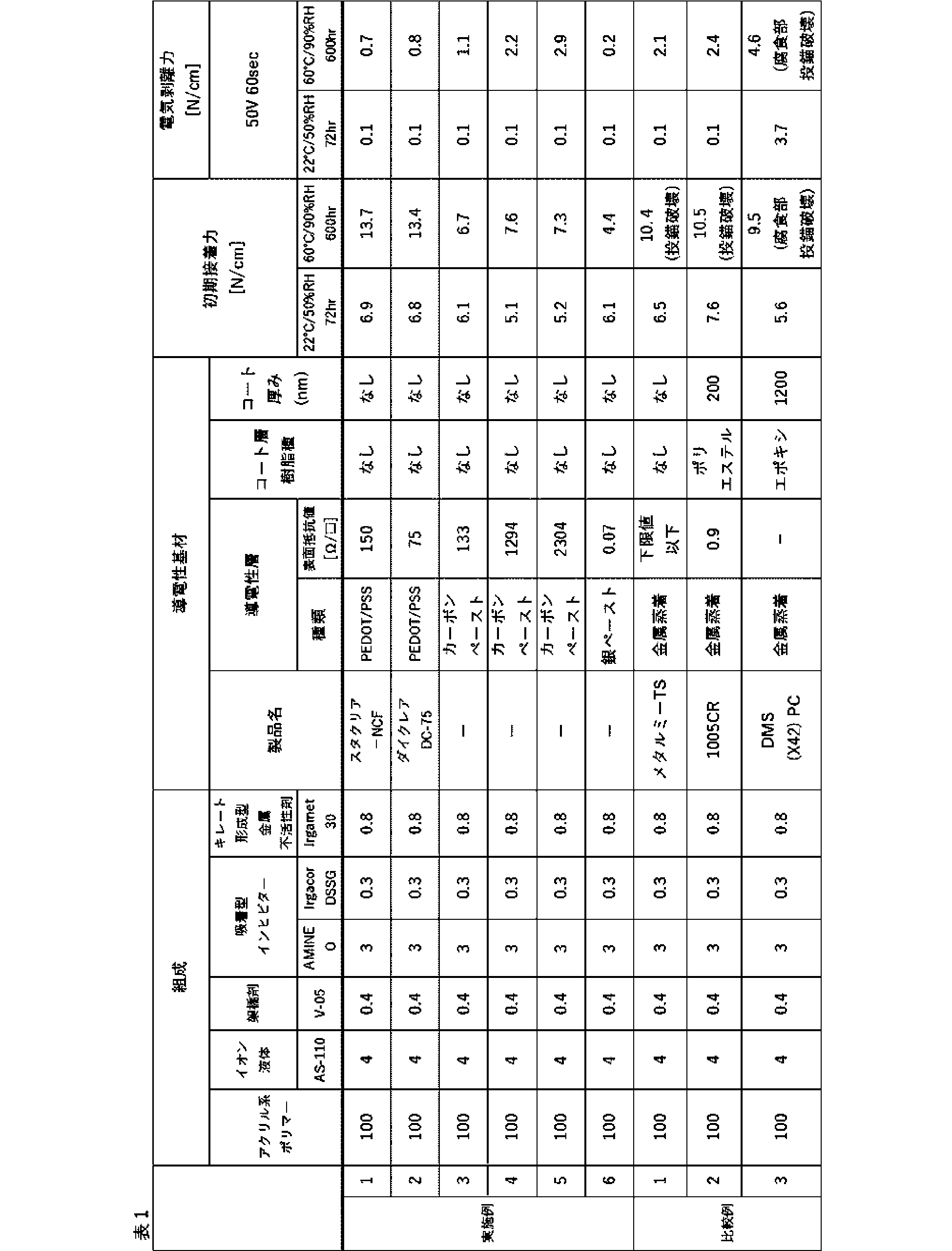
本出願は、2023年3月29日出願の日本特許出願(特願2023-54108)、及び2024年1月31日出願の日本特許出願(特願2024-13137)に基づくものであり、その内容はここに参照として取り込まれる。
1 電気剥離型粘着剤層
3 導電性層
4 支持基材
5 導電性基材
6 その他の粘着剤層
7 導電性被着体
8 積層体
Claims (13)
- 支持基材と樹脂成分を含有する導電性層とを含む導電性基材と、
電圧の印加により粘着力が低下する電気剥離型粘着剤層とを備え、
前記電気剥離型粘着剤層と前記導電性層とが接している、電気剥離型粘着シート。 - 前記電気剥離型粘着剤層は、ポリマー及びイオン液体を含有する、請求項1に記載の電気剥離型粘着シート。
- 前記イオン液体のアニオンは、ビス(フルオロスルホニル)イミドアニオン、およびビス(トリフルオロメタンスルホニル)イミドアニオンからなる群より選択される少なくとも1種である、請求項2に記載の電気剥離型粘着シート。
- 前記イオン液体のカチオンは、窒素含有オニウムカチオン、硫黄含有オニウムカチオン、及びリン含有オニウムカチオンからなる群より選択される少なくとも1種である、請求項2に記載の電気剥離型粘着シート。
- 前記導電性層が、導電性ポリマーを含む、請求項1又は2に記載の電気剥離型粘着シート。
- 前記導電性ポリマーが、PEDOT/PSS、ポリアセチレン系ポリマー、ポリアニリン系ポリマー、及びポリピロール系ポリマーから選択される少なくとも1種を含む、請求項5に記載の電気剥離型粘着シート。
- 前記導電性層が、さらに導電性フィラーを含む、請求項1又は2に記載の電気剥離型粘着シート。
- 前記導電性フィラーが、カーボン粒子、又は金属粒子である、請求項7の電気剥離型粘着シート。
- 前記導電性層の表面抵抗値が5000Ω/□以下である、請求項1又は2に記載の電気剥離型粘着シート。
- さらにその他の粘着剤層を備え、
前記支持基材の前記導電性層とは反対側の面上に前記その他の粘着剤層が形成されている、請求項1又は2に記載の電気剥離型粘着シート。 - さらにその他の粘着剤層、樹脂成分を含有する第2の導電性層、及び第2のその他の粘着剤層を備え、
前記支持基材の前記導電性層とは反対側の面上に前記その他の粘着剤層が形成され、
前記電気剥離型粘着剤層の前記導電性層とは反対側の面上に、前記第2の導電性層、及び第2のその他の粘着剤層がこの順に形成され、
前記電気剥離粘着剤層と前記第2の導電性層とが接している、請求項1又は2に記載の電気剥離型粘着シート。 - 請求項1又は2に記載の電気剥離型粘着シートと、導電性の材料を備え、
前記電気剥離型粘着剤層が前記導電性の材料に貼着した接合体。 - 請求項11に記載の電気剥離型粘着シートと、被着体材料と、を備え、前記その他の粘着剤層が、前記被着体材料に貼着した接合体。
Priority Applications (3)
| Application Number | Priority Date | Filing Date | Title |
|---|---|---|---|
| CN202480022620.7A CN120936687A (zh) | 2023-03-29 | 2024-03-27 | 电剥离型粘合片及接合体 |
| JP2025511029A JPWO2024204367A1 (ja) | 2023-03-29 | 2024-03-27 | |
| KR1020257032286A KR20250165353A (ko) | 2023-03-29 | 2024-03-27 | 전기 박리형 점착 시트, 및 접합체 |
Applications Claiming Priority (4)
| Application Number | Priority Date | Filing Date | Title |
|---|---|---|---|
| JP2023-054108 | 2023-03-29 | ||
| JP2023054108 | 2023-03-29 | ||
| JP2024-013137 | 2024-01-31 | ||
| JP2024013137 | 2024-01-31 |
Publications (1)
| Publication Number | Publication Date |
|---|---|
| WO2024204367A1 true WO2024204367A1 (ja) | 2024-10-03 |
Family
ID=92905427
Family Applications (1)
| Application Number | Title | Priority Date | Filing Date |
|---|---|---|---|
| PCT/JP2024/012277 Ceased WO2024204367A1 (ja) | 2023-03-29 | 2024-03-27 | 電気剥離型粘着シート、及び接合体 |
Country Status (5)
| Country | Link |
|---|---|
| JP (1) | JPWO2024204367A1 (ja) |
| KR (1) | KR20250165353A (ja) |
| CN (1) | CN120936687A (ja) |
| TW (1) | TW202506930A (ja) |
| WO (1) | WO2024204367A1 (ja) |
Cited By (4)
| Publication number | Priority date | Publication date | Assignee | Title |
|---|---|---|---|---|
| WO2026099153A1 (en) | 2024-11-05 | 2026-05-15 | Tesa Se | Device capable of bonding and debonding on demand |
| WO2026099181A1 (en) | 2024-11-05 | 2026-05-15 | Tesa Se | Device capable of stain-free debonding on demand |
| WO2026099184A1 (en) | 2024-11-05 | 2026-05-15 | Tesa Se | Anti-corrosion adhesive device |
| WO2026155040A1 (ja) * | 2025-01-17 | 2026-07-23 | 日東電工株式会社 | 両面粘着シート、接合体、電気電子機器、および粘着シートの製造方法 |
Citations (6)
| Publication number | Priority date | Publication date | Assignee | Title |
|---|---|---|---|---|
| JP2003504504A (ja) * | 1999-07-14 | 2003-02-04 | イーアイシー ラボラトリーズ インコーポレーティッド | 電気的結合解除物質 |
| JP2011052056A (ja) * | 2009-08-31 | 2011-03-17 | Big Technos Kk | 電気剥離性粘着製品及びその剥離方法 |
| WO2021202527A1 (en) * | 2020-03-30 | 2021-10-07 | Nitto Denko Corporation | Electrically peelable composition for high temperature exposure |
| WO2022030565A1 (ja) * | 2020-08-07 | 2022-02-10 | 日東電工株式会社 | 電気剥離型粘着シート、及び接合体 |
| WO2022163593A1 (ja) * | 2021-01-29 | 2022-08-04 | 日東電工株式会社 | 電気剥離用粘着剤組成物、粘着シート、及び接合体 |
| WO2022165375A1 (en) * | 2021-01-29 | 2022-08-04 | Nitto Denko Corporation | Corrosion resistant high voltage electrochemically de-bondable adhesive composition |
Family Cites Families (1)
| Publication number | Priority date | Publication date | Assignee | Title |
|---|---|---|---|---|
| JP7645090B2 (ja) | 2021-02-18 | 2025-03-13 | 東レフィルム加工株式会社 | 導電性フィルム及びそれを用いた積層体 |
-
2024
- 2024-03-27 KR KR1020257032286A patent/KR20250165353A/ko active Pending
- 2024-03-27 JP JP2025511029A patent/JPWO2024204367A1/ja active Pending
- 2024-03-27 CN CN202480022620.7A patent/CN120936687A/zh active Pending
- 2024-03-27 WO PCT/JP2024/012277 patent/WO2024204367A1/ja not_active Ceased
- 2024-03-29 TW TW113112047A patent/TW202506930A/zh unknown
Patent Citations (6)
| Publication number | Priority date | Publication date | Assignee | Title |
|---|---|---|---|---|
| JP2003504504A (ja) * | 1999-07-14 | 2003-02-04 | イーアイシー ラボラトリーズ インコーポレーティッド | 電気的結合解除物質 |
| JP2011052056A (ja) * | 2009-08-31 | 2011-03-17 | Big Technos Kk | 電気剥離性粘着製品及びその剥離方法 |
| WO2021202527A1 (en) * | 2020-03-30 | 2021-10-07 | Nitto Denko Corporation | Electrically peelable composition for high temperature exposure |
| WO2022030565A1 (ja) * | 2020-08-07 | 2022-02-10 | 日東電工株式会社 | 電気剥離型粘着シート、及び接合体 |
| WO2022163593A1 (ja) * | 2021-01-29 | 2022-08-04 | 日東電工株式会社 | 電気剥離用粘着剤組成物、粘着シート、及び接合体 |
| WO2022165375A1 (en) * | 2021-01-29 | 2022-08-04 | Nitto Denko Corporation | Corrosion resistant high voltage electrochemically de-bondable adhesive composition |
Cited By (4)
| Publication number | Priority date | Publication date | Assignee | Title |
|---|---|---|---|---|
| WO2026099153A1 (en) | 2024-11-05 | 2026-05-15 | Tesa Se | Device capable of bonding and debonding on demand |
| WO2026099181A1 (en) | 2024-11-05 | 2026-05-15 | Tesa Se | Device capable of stain-free debonding on demand |
| WO2026099184A1 (en) | 2024-11-05 | 2026-05-15 | Tesa Se | Anti-corrosion adhesive device |
| WO2026155040A1 (ja) * | 2025-01-17 | 2026-07-23 | 日東電工株式会社 | 両面粘着シート、接合体、電気電子機器、および粘着シートの製造方法 |
Also Published As
| Publication number | Publication date |
|---|---|
| JPWO2024204367A1 (ja) | 2024-10-03 |
| TW202506930A (zh) | 2025-02-16 |
| KR20250165353A (ko) | 2025-11-25 |
| CN120936687A (zh) | 2025-11-11 |
Similar Documents
| Publication | Publication Date | Title |
|---|---|---|
| JP7651255B2 (ja) | 粘着剤組成物、粘着シート、及び接合体 | |
| JP7803863B2 (ja) | 電気剥離型粘着シート、及び接合体 | |
| JP2022125167A (ja) | 電気剥離用粘着剤組成物、粘着シート、及び接合体 | |
| US20230159799A1 (en) | Adhesive composition, adhesive sheet, and joined body | |
| JP2025061947A (ja) | 粘着剤組成物、粘着シート、及び接合体 | |
| EP3858932A1 (en) | Adherend separation method and joining method | |
| EP3858929A1 (en) | Joining and separation method for adherends | |
| CN120936687A (zh) | 电剥离型粘合片及接合体 | |
| JP2021161389A (ja) | 粘着剤組成物、粘着シート、及び接合体 | |
| WO2022210055A1 (ja) | 粘着シート、接合体、及び接合体の分離方法 | |
| KR20250101924A (ko) | 전기 박리형 점착 시트, 및 접합체 | |
| WO2025164771A1 (ja) | 電気剥離型粘着シート、及び接合体 | |
| WO2022163593A1 (ja) | 電気剥離用粘着剤組成物、粘着シート、及び接合体 | |
| JP2025104275A (ja) | 電気剥離型粘着シート、及び接合体 | |
| JP2025103669A (ja) | 電気剥離型粘着シート、及び接合体 | |
| WO2025239391A1 (ja) | 電気剥離用粘着剤組成物、電気剥離型粘着シート、及び接合体 | |
| WO2025239393A1 (ja) | 電気剥離用粘着剤組成物、電気剥離型粘着シート、及び接合体 | |
| WO2026070882A1 (ja) | 導電性組成物、導電性層、導電性層を有する被着体、接合体、及び接合体の分離方法 |
Legal Events
| Date | Code | Title | Description |
|---|---|---|---|
| 121 | Ep: the epo has been informed by wipo that ep was designated in this application |
Ref document number: 24780469 Country of ref document: EP Kind code of ref document: A1 |
|
| ENP | Entry into the national phase |
Ref document number: 2025511029 Country of ref document: JP Kind code of ref document: A |
|
| WWE | Wipo information: entry into national phase |
Ref document number: 2025511029 Country of ref document: JP |
|
| ENP | Entry into the national phase |
Ref document number: 1020257032286 Country of ref document: KR Free format text: ST27 STATUS EVENT CODE: A-0-1-A10-A15-NAP-PA0105 (AS PROVIDED BY THE NATIONAL OFFICE) |
|
| WWE | Wipo information: entry into national phase |
Ref document number: KR1020257032286 Country of ref document: KR |
|
| NENP | Non-entry into the national phase |
Ref country code: DE |
|
| 122 | Ep: pct application non-entry in european phase |
Ref document number: 24780469 Country of ref document: EP Kind code of ref document: A1 |