WO2024203190A1 - 演算装置 - Google Patents
演算装置 Download PDFInfo
- Publication number
- WO2024203190A1 WO2024203190A1 PCT/JP2024/009203 JP2024009203W WO2024203190A1 WO 2024203190 A1 WO2024203190 A1 WO 2024203190A1 JP 2024009203 W JP2024009203 W JP 2024009203W WO 2024203190 A1 WO2024203190 A1 WO 2024203190A1
- Authority
- WO
- WIPO (PCT)
- Prior art keywords
- matrix
- data
- calculation
- submap
- memory
- Prior art date
- Legal status (The legal status is an assumption and is not a legal conclusion. Google has not performed a legal analysis and makes no representation as to the accuracy of the status listed.)
- Ceased
Links
Images


Classifications
-
- G—PHYSICS
- G06—COMPUTING OR CALCULATING; COUNTING
- G06F—ELECTRIC DIGITAL DATA PROCESSING
- G06F17/00—Digital computing or data processing equipment or methods, specially adapted for specific functions
- G06F17/10—Complex mathematical operations
-
- G—PHYSICS
- G06—COMPUTING OR CALCULATING; COUNTING
- G06F—ELECTRIC DIGITAL DATA PROCESSING
- G06F17/00—Digital computing or data processing equipment or methods, specially adapted for specific functions
- G06F17/10—Complex mathematical operations
- G06F17/16—Matrix or vector computation, e.g. matrix-matrix or matrix-vector multiplication, matrix factorization
-
- G—PHYSICS
- G06—COMPUTING OR CALCULATING; COUNTING
- G06N—COMPUTING ARRANGEMENTS BASED ON SPECIFIC COMPUTATIONAL MODELS
- G06N3/00—Computing arrangements based on biological models
- G06N3/02—Neural networks
- G06N3/04—Architecture, e.g. interconnection topology
- G06N3/0464—Convolutional networks [CNN, ConvNet]
Definitions
- the present invention relates to a calculation device that performs matrix calculations such as convolution calculations.
- CNNs convolutional neural networks
- image recognition the input image is transformed using convolutional layers and pooling layers, gradually reducing the amount of data, and finally outputting the probability value for each classification.
- a filter multiplication operation is performed on each coordinate region (e.g., a 3x3 cell region) in the input data.
- the calculation result is then used as the input for the calculation in the next layer, and the convolution operation is repeated.
- machine learning using a CNN requires many matrix calculations and memory bandwidth.
- a configuration is used that skips calculations when the calculation target is zero (e.g., Patent Documents 1 and 2, etc.).
- Patent Documents 1 and 2 do not involve calculations, and therefore can reduce calculation time. As a result, the time required for the entire convolution operation can also be reduced.
- the data used as input for the operation target is loaded into a calculation memory, and a determination is made as to whether the data loaded into the calculation memory is zero or not. In other words, if the calculation is skipped as a result, the time and memory space required to read the data is used for data not used in the calculation.
- the present invention was made in consideration of the above-mentioned circumstances, and aims to provide a calculation device that can reduce the time that is wasted when performing matrix calculations such as convolution operations, and can further shorten the time required for the entire calculation compared to conventional methods.
- the present invention employs the following technical means.
- the calculation device comprises a data memory, a matrix calculation unit, a zero check unit, a submap memory, and a map check unit.
- the data memory stores the data to be calculated.
- the matrix calculation unit reads data from the data memory, performs a matrix calculation, and stores the output matrix in the data memory.
- the zero check unit judges whether each element of the output matrix falls within a pre-specified range.
- the submap memory stores the judgment result of the zero check unit as status information.
- the map check unit judges, based on the status information stored in the submap memory, whether to cause the matrix calculation unit to read out the output matrix corresponding to the status information as the data to be calculated.
- the matrix calculation unit may simultaneously read out multiple pieces of data for successively calculating the same output matrix.
- the zero check unit uses one of the multiple pieces of status information corresponding to the multiple pieces of data as status information for the multiple pieces of data successively read out to the matrix calculation unit.
- the above-mentioned configuration can also be applied to cases where the above-mentioned matrix calculation is, for example, a convolution operation in a convolutional neural network.
- the matrix calculation unit stores the output matrix in the data memory as the calculation target data of the next layer in the convolution operation.
- the map check unit determines whether or not to read the output matrix corresponding to the state information stored in the submap memory as the calculation target data of the next layer in the convolution operation to the matrix calculation unit.
- a configuration can be adopted in which the matrix calculation unit reads out the same coordinate area that constitutes a part of each input channel as the calculation target data in all input channels belonging to the same layer in the convolution operation and performs matrix calculation.
- a configuration can also be adopted in which the matrix calculation unit reads out multiple data for which matrix calculation is to be performed continuously at the same layer in the convolution operation at one time.
- the zero check unit uses one of multiple state information corresponding to the multiple data as the state information of the multiple data continuously read out to the matrix calculation unit.
- the above-mentioned arithmetic device may also be configured to further include a table creation unit and a read control unit.
- the table creation unit creates a table that specifies the output matrix to be read by the matrix calculation unit based on the determination result of the map check unit.
- the read control unit causes the matrix calculation unit to read data based on the created table.
- the zero check unit further determines whether or not each element of the output matrix by the matrix calculation unit falls within a pre-specified range in units of memory access.
- the submap memory stores the determination result of the zero check unit as the second state information.
- a configuration can be adopted in which the map check unit executes matrix calculations for the first layer and beyond based on state information stored in the submap memory as a result of the initial matrix calculation for the first layer in the convolution calculation.
- the above-mentioned arithmetic device may be further configured to include a submap memory buffer that stores, in association with each other, information for identifying an output matrix corresponding to state information, information indicating the storage location of the state information in the submap memory, and information indicating whether the state information has been used in the convolution calculation of the next layer.
- a storage location in the submap memory that is associated with usage information indicating use in the convolution calculation of the next layer is selected as the storage location in the submap memory for the newly generated state information.
- the above-mentioned calculation device can also be configured to have the submap memory store in advance kernel state information that has been determined for each element of the kernel used in the above-mentioned matrix calculation as being within a pre-specified range.
- the map check unit determines, based on the state information and kernel state information stored in the submap memory, whether or not to cause the matrix calculation unit to read out the output matrix corresponding to the state information as data to be calculated.
- the zero check unit compares each element of the output matrix with multiple thresholds and determines which of multiple ranges defined by the multiple thresholds all elements of the output matrix belong to.
- the zero check unit further determines whether or not a negative value exists in each element of the output matrix, or the number of elements that belong to one of a plurality of ranges.
- the zero check unit creates status information during matrix calculation for the input channel that is the last to be calculated among input channels belonging to the same layer, and stores the information in the submap memory.
- FIG. 1 is a schematic diagram showing an example of a calculation device according to an embodiment of the present invention.
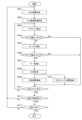
- FIG. 2 is a flow diagram showing the procedure of a convolution calculation by a calculation device according to an embodiment of the present invention.
- FIG. 3 is a flow diagram showing the procedure of a convolution calculation by a calculation device according to an embodiment of the present invention.
- FIG. 4 is a schematic configuration diagram showing an example of a zero check unit included in the arithmetic device according to an embodiment of the present invention.
- FIG. 5 is a schematic diagram showing an example of a sub-map included in the arithmetic device according to an embodiment of the present invention.
- FIG. 6 is a schematic diagram showing an example of a calculation device according to an embodiment of the present invention.
- FIG. 1 is a schematic diagram showing an example of a calculation device according to an embodiment of the present invention.
- FIG. 2 is a flow diagram showing the procedure of a convolution calculation by a calculation device according to an embodiment of the present invention.
- FIG. 7 is a schematic diagram showing an example of a submap address table included in the arithmetic unit according to one embodiment of the present invention.
- FIG. 8 is a flow diagram showing the procedure of a convolution calculation by a calculation device according to an embodiment of the present invention.
- FIG. 9 is a flow diagram showing the procedure of a convolution calculation by a calculation device according to an embodiment of the present invention.
- FIG. 10 is an explanatory diagram that illustrates the concept of a convolution calculation method by a calculation device according to an embodiment of the present invention.
- FIG. 11 is a flow diagram showing the procedure of a convolution calculation by a calculation device according to an embodiment of the present invention.
- FIG. 12 is a flow diagram showing the procedure of a convolution calculation by a calculation device according to an embodiment of the present invention.
- FIG. 13 is an explanatory diagram that illustrates the concept of a convolution calculation method by a calculation device according to an embodiment of the present invention.
- FIG. 14 is a schematic diagram showing an example of a calculation device according to an embodiment of the present invention.
- FIG. 15 is a flow diagram showing the procedure of a convolution calculation by a calculation device according to an embodiment of the present invention.
- 16(a) and 16(b) are explanatory diagrams that diagrammatically show the concept of a convolution calculation method by a calculation device according to one embodiment of the present invention.
- a calculation device which uses the output matrix of a previous matrix calculation as the calculation target data for a subsequent matrix calculation in a series of matrix calculations, is embodied as a calculation device that realizes the processing of the convolution layer of a convolutional neural network (CNN).
- CNN convolutional neural network
- a convolutional neural network includes a convolutional layer and a pooling layer.
- the amount of input data such as an image to be recognized, gradually decreases as a series of processes in the convolutional layer and the pooling layer are repeatedly performed.
- the convolutional neural network then ultimately outputs a classification probability value that indicates the type of object the input image is.
- the recognition target is an image
- data in which each pixel value is arranged two-dimensionally for each input channel of R, G, and B of each pixel of the image is input as input data to the convolution layer.
- a kernel filter
- a coordinate region e.g., a 3 ⁇ 3 region
- the results calculated for each input channel are added together to calculate the output value of that coordinate region.
- This multiplication with the kernel is performed on the entire input image by sequentially moving the coordinate region in each input channel while a portion of the coordinate region overlaps.
- multiple sets of kernels are prepared for each input channel according to the number of output channels output by the convolution operation. For example, if the input data is three channels and the output data is three channels, three kernel sets consisting of three kernels that are multiplied to the coordinate region of each input channel are prepared.
- output values are calculated by processing the data for each coordinate region of the two-dimensional data (output matrix) output as the result of the calculations in the convolution layer. For example, in the pooling layer, the average or maximum value in a 2x2 coordinate region is output as the output value for that coordinate region. Note that the pooling layer may be omitted. When the pooling layer is omitted, the data output by the convolution calculation in the first layer is used as input data to carry out the convolution calculation in the second layer.
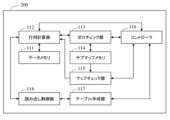
- FIG. 1 is a schematic diagram showing the configuration of a calculation device in one embodiment of the present invention.
- the calculation device 100 of this embodiment includes a data memory 111, a matrix calculation unit 112, a zero check unit 113, a submap memory 114, a map check unit 115, and a controller 116.
- the calculation device 100 creates a submap separate from the output matrix (main map) obtained as the calculation result in a conventional convolution calculation, and uses the submap to reduce the time required for the entire convolution calculation.
- a submap is created for each input channel used as input data for the convolution calculation in the next layer.
- the data memory 111 stores the data to be calculated. As described above, when an image is the object of calculation, for example, the pixel values of each pixel constituting the image are stored in the data memory 111 as input data. In this embodiment, the data memory 111 also stores the kernel and bias described below that are used for the matrix calculation in the matrix calculation unit 112.
- the matrix calculation unit 112 stores an output matrix (output channel), which is the result of the matrix calculation for the entire input data, in the data memory 111 as the data to be calculated in the next layer in the convolution calculation.
- the matrix calculation unit 112 outputs, as an output value, the sum of the elements of the calculation matrix Q, which is the result of performing the above matrix calculation for the coordinate area of each input channel.
- the matrix calculation unit 112 performs the matrix calculation for the entire input data, and stores the output value for each coordinate area in the data memory 111 together with information indicating the coordinate area. Therefore, when the matrix calculation for the input data is completed, the data memory 111 stores the output matrix that is the result of performing the matrix calculation (convolution operation) on the entire input data.
- the matrix calculation unit 112 first performs matrix calculations for each coordinate region for one of the three input channels.
- the data memory 111 stores an output matrix resulting from the matrix calculations for one input channel.
- the matrix calculation unit 112 performs matrix calculations for each coordinate region for one of the remaining two input channels.
- a bias a matrix in which elements other than those corresponding to the coordinate region being calculated are set to zero in the output matrix for the first input channel stored in the data memory 111 is used.
- the data memory 111 stores an output matrix in which the result of the matrix calculation for the first input channel and the result of the matrix calculation for the second input channel are added together.
- the matrix calculation unit 112 performs matrix calculations for each coordinate region for the remaining input channel.
- a matrix in which all elements other than those corresponding to the coordinate region being calculated are set to zero in the output matrices for the first and second input channels stored in the data memory 111 are used as the bias.
- the data memory 111 stores an output matrix in which the results of the matrix calculation for the three input channels are added together.
- the zero check unit 113 judges whether each element of the output matrix output by the matrix calculation unit 112, i.e., the output value of the matrix calculation for each coordinate region, falls within a pre-specified range. Although not limited to this, in this embodiment, the zero check unit 113 judges which of a number of ranges defined by a number of pre-set threshold values the element belongs to. As described below, in this embodiment, the zero check unit 113 is configured to make the above-mentioned judgment each time an output value is output from the matrix calculation unit 112, based on the state information stored in the submap memory 114 at that time and the output value from the matrix calculation unit 112.
- the submap memory 114 stores the judgment result of the zero check unit 113 as state information.
- the state information is stored in correspondence with the output matrix described above.
- the state information is one of the pieces of information that constitute the submap described above.
- the state information is information indicating which of four states the state belongs to. That is, the state information is information indicating which of the four states the state belongs to: "state 1" where all the elements of the output matrix are equal to or less than the first threshold, "state 2" where all the elements of the output matrix are equal to or less than the second threshold, "state 3" where all the elements of the output matrix are equal to or less than the third threshold, and "state 4" where the state is neither state 1, state 2, nor state 3.
- the numerical values "0", “1", “2”, and “3" are stored as information indicating state 1, state 2, state 3, and state 4, respectively.
- the state information is updated each time the zero check unit 113 makes a judgment.
- the submap memory 114 may be configured as part of the memory device that constitutes the data memory 111, or may be configured as a separate memory device.
- the map check unit 115 judges whether or not to have the matrix calculation unit 112 read out the output matrix corresponding to the state information as input data (data to be calculated) for the next layer in the convolution calculation. For example, in the above example, the following judgment is made. If the state information is state 1, the map check unit 115 judges not to read out the data (output matrix) corresponding to the matrix calculation unit 112. If the state information is state 2 or state 3, the map check unit 115 judges not to read out the data (output matrix) corresponding to the matrix calculation unit 112 when the value of kernel A satisfies a preset condition.
- the preset condition is, for example, state 2 where more than half of the kernel elements are zero, state 3 where more than 3/4 of the kernel elements are zero, etc. Also, if the state information is state 4, the map check unit 115 judges to read out the data (output matrix) corresponding to the matrix calculation unit 112.
- the calculation device 100 also includes a controller 116 that controls the operation timing of the data memory 111, matrix calculation unit 112, zero check unit 113, submap memory 114, and map check unit 115.
- the matrix calculation unit 112 can be realized by a processor, such as a GPU (Graphic Processing Unit) specialized for image processing.
- a processor such as a GPU (Graphic Processing Unit) specialized for image processing.
- each element that performs signal processing and data processing such as the zero check unit 113, map check unit 115, and controller 116, can be realized by, for example, a dedicated arithmetic circuit, or hardware equipped with a processor and memory such as RAM (Random Access Memory) or ROM (Read Only Memory), and software that is stored in the memory and runs on the processor.
- RAM Random Access Memory
- ROM Read Only Memory
- the operation of the arithmetic device 100 having the above configuration will be described.
- a convolution operation is performed on input data
- a submap including state information is created for each output matrix used as an input channel for the convolution operation of the next layer. That is, the submap created during the convolution operation of the first layer is used during the convolution operation of the second layer, and the submap created during the convolution operation of the second layer is used during the convolution operation of the third layer. Therefore, in the convolution operation of the first layer, there are no submaps corresponding to each input channel.
- the operation during the convolution operation of the first layer and the convolution operations of the second layer and onwards will be described.
- FIG. 2 is a flow diagram showing the procedure performed during the first layer convolution calculation of the calculation device 100 of this embodiment. Note that FIG. 2 shows an example in which the number of input channels is n and the number of output channels is m. Although not particularly limited, this procedure is started, for example, when the data to be calculated is stored in the data memory 111 from outside the calculation device 100.
- the matrix calculation unit 112 starts matrix calculation for the first input channel.
- the matrix calculation unit 112 first reads out the kernel to be used for the matrix calculation for the first input channel from the data memory 111 (step S201).
- the matrix calculation unit 112 also reads out the data belonging to the coordinate region to be used for the matrix calculation from the input data belonging to the first input channel from the data memory 111, and the bias described above (step S202).
- the bias for the first input channel is a zero matrix.
- the matrix calculation unit 112 executes a matrix calculation, and stores the output value, which is the calculation result, in the data memory 111 together with information indicating the coordinate region (steps S203 and S204).
- the matrix calculation unit 112 inputs the output value to the zero check unit 113.
- the zero check unit 113 determines which of a number of ranges defined by a number of preset thresholds the value belongs to.
- the zero check unit 113 then stores the determination result in the submap memory 114, and updates the state information already stored (step S205).
- the calculation device 100 repeats the above process until it is completed for all coordinate regions belonging to the first input channel (step S206: No). At this time, the data memory 111 stores the output matrix calculated for the first input channel.
- the matrix calculation unit 112 starts the matrix calculation for the second input channel (step S206: Yes, S207: No).
- the matrix calculation unit 112 reads the kernel to be used for the matrix calculation for the second input channel from the data memory 111 (step S201).
- the matrix calculation unit 112 also reads the data belonging to the coordinate region to be used for the matrix calculation from the input data belonging to the second input channel, and the bias from the data memory 111 (step S202).
- the bias for the second input channel is a matrix in which all elements of the output matrix being calculated that are stored in the data memory 111 at that time are set to zero except for the elements corresponding to the coordinate region to be calculated.
- the matrix calculation unit 112 executes a matrix calculation, and stores the output value, which is the calculation result, in the data memory 111 together with information indicating the coordinate region (steps S203 and S204).
- the matrix calculation unit 112 inputs the output value to the zero check unit 113.
- the zero check unit 113 determines which of a number of ranges defined by a number of preset thresholds the value belongs to.
- the zero check unit 113 then stores the determination result in the submap memory 114, and updates the state information already stored (step S205).
- the calculation device 100 repeats the above process until it is completed for all coordinate regions belonging to the second input channel (step S206: No).
- the data memory 111 stores an output matrix that is the sum of the results of the matrix calculation for the first input channel and the results of the matrix calculation for the second input channel.
- the data memory 111 will store an output matrix that is the result of performing matrix calculations on the entire input data (all input channels).
- m output matrices are stored in the data memory 111, and m submaps corresponding to each output matrix are stored in the submap memory 114.
- These m output matrices are used as input channels for the convolution calculation of the next layer.
- FIG. 3 is a flow diagram showing the procedure performed during convolution calculations from the second layer onward in the calculation device 100 of this embodiment. Note that FIG. 3 shows an example in which the number of input channels is n and the number of output channels is m. The number of input channels n is equal to the number m of output matrices (output channels) calculated by the convolution calculation of the immediately preceding layer. This procedure is started, for example, when the convolution calculation of the immediately preceding layer is completed.
- the map check unit 115 reads the submap corresponding to the first input channel from the submap memory 114 and checks the status information contained in that submap (step S301).
- the map check unit 115 reads the submap corresponding to the second input channel from the submap memory 114 and checks the status information contained in the submap (steps S302 Yes, S310 No, S301).
- the map check unit 115 causes the matrix calculation unit 112 to read a kernel to be used for the matrix calculation for the first input channel from the data memory 111. Then, it is confirmed whether or not the kernel satisfies the above-mentioned conditions (steps S302: No, S303). If the kernel satisfies the above-mentioned conditions, the map check unit 115 reads a submap corresponding to the second input channel from the submap memory 114, and checks the state information included in the submap (steps S304: Yes, S310: No, S301).
- the map check unit 115 causes the matrix calculation unit 112 to execute a matrix calculation (step S302: No).
- the matrix calculation unit 112 reads out the kernel to be used for the matrix calculation for the first input channel from the data memory 111 (steps S302: No, S303).
- the matrix calculation unit 112 also reads out the data belonging to the coordinate region to be used for the matrix calculation from the input data belonging to the first input channel, and the above-mentioned bias from the data memory 111 (steps S304: No, S305).
- each of the multiple output matrices calculated in the k-1th layer convolution calculation is used as an input channel.
- the matrix calculation unit 112 executes a matrix calculation, and stores the output value, which is the calculation result, in the data memory 111 together with information indicating the coordinate region (steps S306 and S307).
- the matrix calculation unit 112 inputs the output value to the zero check unit 113.
- the zero check unit 113 determines which of a number of ranges defined by a number of preset thresholds the value belongs to.
- the zero check unit 113 then stores the determination result in the submap memory 114, and updates the state information already stored (step S308).
- the calculation device 100 repeats the above process until it is completed for all coordinate regions belonging to the first input channel (step S309 No).
- the data memory 111 stores the output matrix that is the result of performing matrix calculations on the entire input data (all input channels).
- state information is created based on each element of the output matrix of the convolution operation in the immediately preceding layer, and when the state information satisfies a pre-specified condition, the matrix calculation using the input channel corresponding to that state information is skipped. Also, at this time, data belonging to that input channel is not read from the data memory 111 to the matrix calculation unit 112. In other words, since the reading of unnecessary data does not occur, it is possible to further reduce the wasted data read time, and the time required for the entire calculation can be further shortened compared to the conventional method.
- FIG. 4 is a schematic diagram showing an example of the zero check unit 113 provided in the arithmetic device 100.
- the zero check unit 113 has an input terminal 31, a comparison terminal 32, and an output terminal 33.
- the input terminal 31 receives an output value from the matrix calculation unit 112.
- the comparison terminal 32 receives state information stored in the submap memory 114.
- the output terminal 33 outputs data to be stored in the submap memory 114.
- the output value from the matrix calculation unit 112 input through the input terminal 31 is input to the comparison unit 34 having multiple comparators.
- the comparison unit 34 has a number of comparators equal to or greater than the number of preset thresholds. As described above, in this embodiment, three thresholds are set, so the comparison unit 34 has three comparators 34a, 34b, and 34c.
- the output value from the matrix calculation unit 112 is input to one input terminal of each of the comparators 34a, 34b, and 34c, and the threshold is input to the other input terminal.
- the comparators 34a, 34b, and 34c are configured to output the numerical value "1".
- each comparator 34a, 34b, 34c is input to checker 35.
- the status information stored in submap memory 114 at that time is input to checker 35 via comparison terminal 32.
- the status information stored in submap memory 114 is a number between "0" and "3.”
- the checker 35 When the output of each of the comparators 34a, 34b, and 34c includes the value "1" and the status information stored in the submap memory 114 needs to be updated, the checker 35 outputs an output corresponding to the updated status information to the output terminal 33. For example, when the stored status information is "0", the checker 35 updates the status information to one of the values “1", “2", or “3” according to the output of each of the comparators 34b and 34c when at least the output of the comparator 34a is the value "1". When the stored status information is "1”, the checker 35 updates the status information to one of the values "2" or “3” according to the output of the comparator 34c when at least the output of the comparator 34b is the value "1". When the stored status information is "2”, the checker 35 updates the status information to the value "3” when the output of the comparator 34c is the value "1". When the stored status information is "3", the checker 35 does not update the status information.
- the zero check unit 113 when the convolution operation to obtain one output matrix is completed, the status information corresponding to that output matrix is stored in the submap memory 114.
- the zero check unit 113 can also be realized with other configurations. For example, a configuration can be adopted in which the zero check unit 113 holds a cumulative value of the number of output values that belong to each range. In this case, each time an output value is output from the matrix calculation unit 112, the zero check unit 113 can determine which of the above-mentioned multiple ranges it belongs to based on the held cumulative value.
- the zero check unit 113 is configured to be able to make the above-mentioned judgments as well as make negative judgments as to whether or not the elements of the output matrix contain negative values, and to count the number of elements in the output matrix that exceed any of the above-mentioned thresholds.
- negative judgment information indicating the result of the negative judgment and counting information indicating the coefficient result are stored in the submap memory 114.
- the negative judgment information and counting information, together with the above-mentioned state information, are information that constitutes the above-mentioned submap.
- the zero check unit 113 includes a comparator 34d in the comparison unit 34, one input terminal of which receives the output value from the matrix calculation unit 112 and the other input terminal of which receives the numerical value "0".
- the comparator 34d is configured to output the numerical value "1" when the input output value from the matrix calculation unit 112 is smaller than "0".
- the output of the comparator 34d is input to the OR circuit 36.
- the negative judgment information stored in the submap memory 114 at that time is also input to the OR circuit 36 via the comparison terminal 32. If either the output of the comparator 34d or the negative judgment information stored in the submap memory 114 is the numerical value "1", the OR circuit 36 outputs the numerical value "1" to the output terminal 33.
- the convolution operation for obtaining one output matrix is completed, if the element of the output matrix contains a negative value, the numerical value "1" is stored in the submap memory 114 as the negative judgment information. Furthermore, if the elements of the output matrix do not contain negative values, the numerical value "0" will be stored in the submap memory 114 as negative determination information.
- the zero check unit 113 also includes a selector 37 to which the outputs of the comparators 34a, 34b, and 34c are input.
- the selector 37 inputs one of the outputs of the comparators 34a, 34b, and 34c that is set in advance to a counter 38.
- the counter 38 also receives the count information stored in the submap memory 114 at that time via a comparison terminal 32.
- the counter 38 outputs a value obtained by adding "1" to the stored count information to the output terminal 33.
- the selector 36 is set to a state in which it outputs the output value of the comparator 34c. According to this configuration, when the convolution operation for obtaining one output matrix is completed, the count value of the elements contained in the output matrix that are greater than the third threshold is stored in the submap memory 114 as count information.
- the above-mentioned negative determination information can be used as a flag to determine which process to implement when the process differs depending on whether or not there is a negative value.
- the count information can perform a process such as skipping the corresponding output matrix (input channel) without reading it out if the total number of elements exceeds a preset threshold value.
- FIG. 5 is a diagram showing an example of a submap.
- a submap using 1 byte (8 bits) of data is shown here as an example.
- the submap 40 includes status information, negative judgment information, and count information.
- the submap 40 is composed of 2 bits of status information, 1 bit of negative judgment information, and 5 bits of count information.
- the address information of the submap 40 in the submap memory 114 and the address information of the output matrix (next layer input channel) corresponding to the submap 40 stored in the data memory 111 are mutually related. This relationship is, for example, such that the top address of the submap 40 is an address obtained by adding a pre-specified offset to the top address of the output matrix corresponding to the submap 40.
- the zero check unit 113 updates the state information in steps S205 and S308 each time the matrix calculation unit 112 outputs a calculation result.
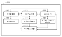
- FIG. 6 is a schematic diagram showing the configuration of a modified example of the arithmetic device in one embodiment of the present invention. Note that in Figure 6, components that achieve the same effects as the arithmetic device 100 are given the same reference numerals as in Figure 1, and detailed description thereof will be omitted below.
- the arithmetic device 300 of this embodiment further includes a submap address buffer 120.
- the arithmetic device 300 creates a submap address table in addition to the submap created by the arithmetic device 100 described above.
- the submap address table is stored in the submap address buffer 120.
- the submap address table 41 is a table in which ID numbers, address information, and usage information are recorded in a linked state.
- the submap address buffer 120 may be configured as part of the memory device that constitutes the submap memory 114 or the memory device that constitutes the data memory 111, or may be configured as a separate memory device.
- the ID number functions as information for identifying a submap. As described above, a submap is created for each input channel used as input data for the convolution operation of the next layer, that is, for each output channel in the layer where the convolution operation is performed. Therefore, the number of ID numbers is the same as the number of output channels.
- a unique number is assigned as the ID number, which is a combination of a number indicating which layer of the convolution operation and a number indicating which output channel. For example, when three output channels are operated in the (k-1)th layer, the ID numbers "k1", “k2", and “k3" are assigned. More specifically, the ID numbers "31”, "32", and “33” are assigned to the three output channels of the second layer. Since these output channels become input channels in the operation of the third layer, when reading out the submap, the address information associated with the ID numbers "31", "32", and "33” is referenced.
- the address information is information that indicates the storage location of the submap in the submap memory 114. More specifically, it is, for example, the starting address of the storage location of the submap. As explained with reference to FIG. 5, the data length (number of bits) of the submap is constant. Therefore, the storage location of the submap in the submap memory 114 can be identified by a single address.
- the usage information indicates whether the linked submap has been used in the convolution calculation of the next layer.
- the usage information is displayed as "valid".
- a submap is created for each input channel that is used as input data for the convolution calculation of the next layer. Therefore, a submap that is read and used in the convolution calculation of the next layer is not used in subsequent convolution calculations.
- the numerical values "0" and "1" are used as information indicating that it has been used and information indicating that it has not been used, respectively.
- a new ID number, address information, and usage information can be linked and stored in a record in the submap address table whose usage information is "0".
- the controller 116 generates the ID number, address information, and usage information, and records them in the submap address table of the submap address buffer 120, but other configurations can also be used.
- a submap address management unit having the function of performing these processes may be provided separately from the controller 116.
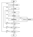
- FIG. 8 is a flow diagram showing the procedure for implementing a method for acquiring data of the same coordinate region for all input channels in the first-layer convolution calculation by the arithmetic device 300.
- FIG. 8 shows an example in which the number of input channels is n and the number of output channels is m.
- the procedure is started, for example, when the data to be calculated is stored in the data memory 111 from outside the arithmetic device 300.
- the arithmetic device 300 differs from the arithmetic device 100 only in that the arithmetic device 300 creates a submap address table. Therefore, in the procedure shown in FIG. 8, steps that perform the same operation as the arithmetic device 100 are given the same reference numerals as in FIG. 2, and detailed description thereof will be omitted below.
- the matrix calculation unit 112 starts the matrix calculation of the first output matrix (output channel).
- the controller 116 generates data for the submap address table (step S220). That is, the controller 116 generates the above-mentioned ID number, address information, and usage information, and records them in the submap address table 41 of the submap address buffer 120. The controller 116 records the generated information in the record in the submap address table 41 whose usage information is "0".
- the ID number "21" is generated at this time.
- An address in the submap memory 114 is appropriately selected as the address information.
- a configuration can be adopted in which all selectable addresses in the submap memory 114 are recorded in the submap address table 41, and the controller 116 selects the address information recorded in the record into which information is to be written as the address information to be linked to the generated ID number. Note that the linked submap has not yet been read, so the usage information recorded is "1".
- the matrix calculation unit 112 starts matrix calculation for the first input channel.
- the procedure for matrix calculation for the first input channel is generally the same as the procedure described in FIG. 2. That is, the kernel reading (step S201), data reading (step S202), matrix calculation (step S203), and calculation result storage (step S204) are as described above.
- the zero check unit 113 stores the determination result in a storage location in the submap memory 114 specified by the address information generated by the controller 116.
- the calculation device 300 repeats the above process until it is completed for all coordinate regions belonging to the first input channel (step S206: No). At this time, the data memory 111 stores the output matrix calculated for the first input channel.
- the matrix calculation unit 112 starts the matrix calculation for the second input channel (step S206: Yes, S207: No).
- the procedure for the matrix calculation for the second input channel is generally the same as the procedure described in FIG. 2. That is, the kernel reading (step S201), data reading (step S202), matrix calculation (step S203), and calculation result storage (step S204) are as described above.
- the zero check unit 113 stores the determination result in a storage location in the submap memory 114 specified by the address information generated by the controller 116.
- the data memory 111 stores an output matrix that is the result of performing a matrix calculation on all input data (all input channels).
- the controller 116 When the matrix calculation unit 112 starts the matrix calculation for the second output matrix (output channel), the controller 116 generates data for the submap address table corresponding to the output matrix (step S220). That is, the controller 116 generates an ID number, address information, and usage information, and records them in the submap address table 41 of the submap address buffer 120.
- the controller 116 records the generated information in the submap address table 41 in a record whose usage information is "0". According to the above-mentioned ID number generation rules, the ID number generated at this time is "22". Furthermore, since the linked submap has not yet been read, the usage information recorded is "1".
- m output matrices When all calculations to obtain a given number m of output matrices are completed, m output matrices will be stored in data memory 111, m submaps corresponding to each output matrix will be stored in submap memory 114, and address information and usage information corresponding to each of the m output matrices will be recorded in submap address buffer 120. These m output matrices will be used as input channels for the convolution operation of the next layer.
- the data for the submap address table is generated at the start of the calculation of the output matrix.
- the data for the table may be generated at other times in the matrix calculation for one output channel, as long as it is generated before the zero check unit 113 first stores the judgment result (state information) in the submap memory 114.
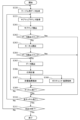
- FIG. 9 is a flow diagram showing the procedure performed by the arithmetic device 300 of this embodiment when performing convolution calculations on the second and subsequent layers.
- FIG. 9 shows an example in which the number of input channels is n and the number of output channels is m.
- the number of input channels n is equal to the number m of output matrices (output channels) calculated by the convolution calculation of the immediately preceding layer. This procedure is started, for example, when the convolution calculation of the immediately preceding layer is completed.
- the arithmetic device 300 differs from the arithmetic device 100 only in that the arithmetic device 300 creates a submap address table. Therefore, in the procedure shown in FIG. 9, steps that perform the same operations as the arithmetic device 100 are given the same reference numerals as in FIG. 3, and detailed explanations thereof will be omitted below.
- the matrix calculation unit 112 starts the matrix calculation of the first output matrix (output channel).
- the controller 116 generates data for the submap address table (step S320). That is, the controller 116 generates the above-mentioned ID number, address information, and usage information, and records them in the submap address table 41 of the submap address buffer 120.
- the controller 116 records the generated information in a record in the submap address table 41 whose usage information is "0". According to the above-mentioned ID number generation rules, the ID number generated at this time is "31". Also, since the linked submap has not yet been read, the usage information recorded is "1".
- the matrix calculation unit 112 starts matrix calculation for the first input channel.
- the map check unit 115 reads address information of the submap corresponding to the first input channel from the submap address buffer 120 (step S321). Then, based on the address information, the map check unit 115 reads the submap corresponding to the first input channel from the submap memory 114 and checks the status information included in the submap (step S301). For example, if the calculation is for the first input channel of the second layer, the map check unit 115 reads address information linked to the ID number "21". In addition, the map check unit 115 notifies the controller 116 of the ID number for which the address information was read from the submap address buffer 120.
- the controller 116 that receives the notification rewrites the usage information linked to the ID number of the submap address buffer 120 from "1" to "0". Note that the rewriting of the usage information can be performed at any timing other than the timing. However, from the perspective of making effective use of the storage area of the submap memory 114, it is preferable to perform this process after the address information is read and before a new submap is stored in the submap memory 114.
- the subsequent procedure for the first input channel is generally the same as that described in FIG. 3, but the zero check unit 113 stores the result of the determination in a storage location in the submap memory 114 specified by the address information generated by the controller 116 (step S308).
- the calculation device 300 repeats the above process until it is completed for all coordinate areas belonging to the first input channel (step S309 No).
- the controller 116 When the matrix calculation unit 112 starts the matrix calculation for the second output matrix (output channel), the controller 116 generates data for the submap address table corresponding to the output matrix (step S320). That is, the controller 116 generates an ID number, address information, and usage information, and records them in the submap address table 41 of the submap address buffer 120.
- the controller 116 records the generated information in the submap address table 41 in a record whose usage information is "0". According to the above-mentioned ID number generation rules, the ID number generated at this time is "32". Furthermore, since the linked submap has not yet been read, the usage information recorded is "1".
- m output matrices When all calculations to obtain a predetermined number m of output matrices are completed, m output matrices will be stored in data memory 111, m submaps corresponding to each output matrix will be stored in submap memory 114, and address information and usage information corresponding to each of the m output matrices will be recorded in submap address buffer 120. These m output matrices are used as input channels for the convolution calculation of the next layer. Then, the calculation device 300 repeatedly performs the procedures performed during the convolution calculation of the second layer and thereafter until all convolution calculations for the specified number of layers are completed.
- the submap memory 114 can be realized using a memory with a limited size, such as a ring buffer.
- a submap is generated only for the data of the input channel used in the convolution operation, and whether or not to read the data of the input channel is determined based on the state information included in the submap.
- state information can also be applied to the kernel used in the matrix calculation of the input data. That is, a configuration can also be adopted in which state information is created for the kernel based on each element of the kernel, and when the state information satisfies a pre-specified condition, the matrix calculation using the kernel corresponding to the state information is skipped without reading the data of the input channel.
- the state information of the kernel can be obtained in advance.
- a configuration can be adopted in which the state information of the kernel is stored in the submap memory 114, and in the judgment of the map check unit 115 in step S302 of FIG. 3 or FIG. 9, in addition to the state information of the input channel, the state information of the kernel is also taken into consideration to determine whether or not to read the data of the input channel.
- the matrix calculation unit 112 performs matrix calculations for one entire input channel, and after completion, performs matrix calculations for the entire next input channel. However, the matrix calculations do not need to be performed continuously for the entire input channel.
- a configuration is described in which matrix calculations are performed for each element of the output matrix. In such a configuration, the matrix calculations are performed for each coordinate region that constitutes part of the input channel.
- Figure 10 is a diagram for explaining the concept of this method. Figure 10 shows an example in which three output matrices (output channels) are obtained from three input channels. Also, in this method, only the order in which data is read by the matrix calculation unit 112 and the like is changed, and the configuration of the arithmetic device is the same as the configuration shown in Figure 1.
- data in the same coordinate region in the three input channels is used to calculate an element located at a specific coordinate in each of the three output matrices.
- data belonging to a 3 ⁇ 3 coordinate region 51a centered on the coordinate (2,3) of the first output matrix 61 is used in the matrix calculation to calculate an element 61a located at the coordinate (2,3) of the first input channel 51, data belonging to a 3 ⁇ 3 coordinate region 52a centered on the coordinate (2,3) of the second input channel 52, and data belonging to a 3 ⁇ 3 coordinate region 53a centered on the coordinate (2,3) of the third input channel 53.
- data belonging to the coordinate region 51a of the first input channel 51, data belonging to the coordinate region 52a of the second input channel 52, and data belonging to the coordinate region 53a of the third input channel 53 are used in the matrix calculation to calculate an element 62a located at the coordinate (2,3) of the second output matrix 62 and an element 63a located at the coordinate (2,3) of the third output matrix 63, although the kernels are different.
- the same output matrix as that calculated in the above embodiment can be calculated by sequentially reading out the data in the coordinate region 51a of the first input channel 51, the data in the coordinate region 52a of the second input channel 52, and the data in the coordinate region 53a of the third input channel 53, and then sequentially reading out the data in the coordinate regions whose positions have been changed in each of the input channels 51, 52, and 53, and performing matrix calculations.
- FIG. 11 is a flow diagram showing the procedure for implementing a method for acquiring data in the same coordinate region for all input channels in the first-layer convolution calculation by the calculation device 100.
- FIG. 11 shows an example in which the number of input channels is n and the number of output channels is m.
- this procedure is started, for example, when the data to be calculated is stored in the data memory 111 from outside the calculation device 100.
- step S701 the coordinates of the elements of the output matrix to be calculated are determined. Then, based on the determined coordinates, the coordinate area of the input channel required for the matrix calculation is identified (step S702). Note that in this embodiment, the controller 116 determines the coordinates of the elements in the output matrix and identifies the coordinate area of the input channel.
- the matrix calculation unit 112 reads from the data memory 111 the kernel to be used for the matrix calculation for the first input channel for the first output matrix (step S703).
- the matrix calculation unit 112 also reads from the data memory 111 the data belonging to the coordinate region of the first input channel and the bias described above (step S704). As described above, the bias for the first input channel is a zero matrix.
- the matrix calculation unit 112 executes the matrix calculation, and stores the output value, which is the calculation result, in the data memory 111 together with information indicating the coordinate area (steps S705 and S706). At this time, the matrix calculation unit 112 inputs the output value to the zero check unit 113. In response to this input, the zero check unit 113 performs the above-mentioned state judgment. The zero check unit 113 then stores the judgment result in the submap memory 114 (step S707).
- the matrix calculation unit 112 reads out from the data memory 111 the kernel to be used for the matrix calculation of the first output matrix for the second input channel (step S708 No, S703).
- the matrix calculation unit 112 also reads out from the data memory 111 the data belonging to the coordinate region of the second input channel and the bias described above (step S704).
- the bias is a matrix in which all elements of the output matrix being calculated that are stored in the data memory 111 at that time, other than the element to be calculated, are set to zero.
- the matrix calculation unit 112 executes the matrix calculation, and stores the output value, which is the calculation result, in the data memory 111 together with information indicating the coordinate area (steps S705 and S706). At this time, the matrix calculation unit 112 inputs the output value to the zero check unit 113. In response to this input, the zero check unit 113 performs the above-mentioned state judgment. The zero check unit 113 then stores the judgment result in the submap memory 114 (step S707).
- the data memory 111 stores the elements of the output matrix that is the result of performing matrix calculations for all input channels.
- the controller 116 determines the coordinates of the next element of the output matrix to be calculated, and identifies the coordinate region of the input channel that corresponds to the determined coordinates (steps S708: Yes, S709: No, S701, S702).
- the calculation device 100 then repeats the above-mentioned processing until it is completed for all elements of the output matrix (step S709: No).
- FIG. 12 is a flow diagram showing the procedure for implementing a method for acquiring data in the same coordinate region for all input channels in the convolution calculation of the second layer and thereafter by the calculation device 100.
- FIG. 12 shows an example in which the number of input channels is n and the number of output channels is m.
- the procedure is started, for example, when the convolution calculation of the immediately preceding layer is completed.
- the controller 116 When this procedure is started, the controller 116 first determines the coordinates of the output matrix elements to be calculated, and then identifies the coordinate region of the input channel required for the matrix calculation based on the determined coordinates (steps S801 and S802).
- the map check unit 115 reads out the submap corresponding to the first input channel for the first output matrix from the submap memory 114, and checks the status information included in the submap (step S803). If the result of the check is that no matrix calculation is to be performed, the map check unit 115 reads out the submap corresponding to the second input channel for the first output matrix from the submap memory 114, and checks the status information included in the submap (steps S804 Yes, S811 No, S803).
- the map check unit 115 causes the matrix calculation unit 112 to read the kernel to be used for the matrix calculation for the first input channel from the data memory 111. Then, it is checked whether the kernel satisfies the above-mentioned conditions (steps S804: No, S805). If the result of the check is that the matrix calculation is not to be performed, the map check unit 115 reads the submap corresponding to the second input channel for the first output matrix from the submap memory 114, and checks the status information included in the submap (steps S806: Yes, S811: No, S803).
- the map check unit 115 causes the matrix calculation unit 112 to execute the matrix calculation (step S806: No).
- the matrix calculation unit 112 reads out data belonging to the coordinate region to be used for the matrix calculation from the input data belonging to the first input channel stored in the data memory 111, and the bias described above (step S807).
- each of the multiple output matrices calculated in the k-1th layer convolution calculation is used as an input channel.
- the matrix calculation unit 112 executes the matrix calculation, and stores the output value, which is the calculation result, in the data memory 111 together with information indicating the coordinate area (steps S808 and S809).
- the matrix calculation unit 112 inputs the output value to the zero check unit 113.
- the zero check unit 113 performs the above-mentioned state judgment.
- the zero check unit 113 stores the judgment result in the submap memory 114 (step S810).
- the data memory 111 stores the elements of the output matrix that is the result of performing matrix calculations for all input channels.
- the controller 116 determines the coordinates of the next element of the output matrix to be calculated, and identifies the coordinate region of the input channel that corresponds to the determined coordinates (steps S811: yes, S812: no, S801, S802).
- the calculation device 100 then repeats the above-mentioned processing until it is completed for all elements of the output matrix (step S812: no).
- the above-mentioned effects can also be obtained with this method.
- state information is created based on each element of the output matrix of the convolution calculation in the immediately preceding layer, and when the state information satisfies a pre-specified condition, the matrix calculation using the input channel corresponding to the state information is skipped.
- the matrix calculation unit 112 skips the data belonging to the input channel from the data memory 111 without reading it. In other words, since the reading of unnecessary data does not occur, the wasted data read time can be reduced, and the time required for the entire calculation can be further shortened compared to the conventional method.
- the zero check unit 113 updates the state information in steps S707 and S810 each time the matrix calculation unit 112 outputs a calculation result.
- step S804 or S806 of the flow diagram shown in FIG. 12 if the reading of input data of all input channels for the same element of the output matrix is skipped, a zero check is not performed on that element. That is, the state information corresponding to that output matrix is not updated to its initial value. For this reason, it is preferable to configure the initial value of the state information to be set to, for example, "0" indicating state 1.
- the output matrix can be skipped without being read as input data in the next layer in the convolution calculation. That is, even if an element of the output matrix is not calculated, a zero clear operation (access to data memory 111) to set the value of that element to zero is not required.
- the matrix calculation unit 112 is configured to read one coordinate domain data for each input channel. However, it is also possible to adopt a configuration in which the matrix calculation unit 112 reads multiple consecutive coordinate domain data for each input channel and writes the results of multiple matrix calculations to the data memory 111. This makes it possible to parallelize the matrix calculations. As can be seen from FIG. 10, reading consecutive coordinate domain data in each input channel and performing matrix calculations is equivalent to performing matrix calculations on consecutive elements in the output matrix.
- the zero check unit 113 stores status information based on any one of the multiple calculated output values in the submap memory 114 as status information for all elements corresponding to the multiple output values.
- FIG. 13 is a diagram for explaining the concept of this method.
- FIG. 13 when the matrix calculation for calculating element 71a located at coordinates (2, 3), element 71b located at coordinates (3, 3), and element 71c located at coordinates (4, 3) of output matrix 71 is parallelized, zero check unit 113 registers the judgment result for any element (for example, element 71c) in submap memory 114 as the judgment result for all elements 71a, 71b, and 71c. This makes it easy to realize parallelization of matrix calculation. Note that here, an example is shown in which three consecutive data are treated as one unit, but if the data is consecutive, this method can also be applied in output matrix units, output matrix row units, and input channel input range units.
- the map check unit 115 checks the state information contained in the submap and selects whether or not to have the matrix calculation unit 113 read the data of the input channel. From the perspective of further reducing the time required for the entire calculation, it is preferable to check as few times as possible.
- FIG. 14 is a schematic diagram showing the configuration of a calculation device that can reduce the number of confirmations.
- the calculation device 200 in addition to the configuration of the calculation device 100 described above, the calculation device 200 includes a table creation unit 117 and a read control unit 118. Note that in FIG. 14, components that achieve the same effects as the calculation device 100 are given the same reference numerals as in FIG. 1, and detailed explanations thereof will be omitted below.
- the table creation unit 117 creates a table that specifies the output matrices to be read as input data by the matrix calculation unit 112 based on the judgment result of the map check unit 115. That is, when starting a convolution operation, the table creation unit 117 first makes the map check unit 115 read state information corresponding to all input channels used in the convolution operation (all output matrices calculated in the convolution operation in the previous layer), and judges whether to make the matrix calculation unit 112 read them as input data using the above-mentioned method. Then, based on the judgment result, the table creation unit 117 creates a table that specifies the input channels to be read as input data by the matrix calculation unit 112.
- the table creation unit 117 creates a table indicating that.
- the table creation unit 117 is configured to hold the created table by itself.
- the read control unit 118 causes the matrix calculation unit 112 to read the data to be calculated based on the table created by the table creation unit 117. As described above, when a table is created indicating that the matrix calculation unit 112 is to read the first and third input channels as input data, the read control unit 118 causes the matrix calculation unit 112 to perform the matrix calculation using only the first and third input channels in the convolution operation.
- the table creation unit 117 and the read control unit can be realized, for example, by hardware including a processor and memory such as RAM or ROM, and by software stored in the memory and running on the processor.
- the operation of the arithmetic device 200 having the above configuration will be described. Even in the arithmetic device 200, the operation differs between the first layer convolution operation where there is no submap and the second layer and subsequent layers where there are submaps. However, the operation of the first layer convolution operation is the same as the operation shown in FIG. 11, so a description thereof will be omitted here.
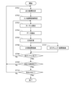
- FIG. 15 is a flow diagram showing the procedure for implementing a method for acquiring data of the same coordinate region for all input channels in the convolution calculation of the second layer and thereafter by the calculation device 200.
- FIG. 15 shows an example in which the number of input channels is n and the number of output channels is m.
- the procedure is started, for example, when the convolution calculation of the immediately preceding layer is completed.
- the table creation unit 117 first causes the map check unit 115 to read out state information corresponding to all input channels, and then uses the method described above to determine whether or not to cause the matrix calculation unit 112 to read out the state information as input data. The table creation unit 117 then creates the above-mentioned table based on the result of this determination (step S1101).
- the controller 116 determines the coordinates of the elements of the output matrix to be calculated, and, based on the determined coordinates, identifies the coordinate region of the input channel required for the matrix calculation (steps 1102, S1103).
- the read control unit 118 instructs the matrix calculation unit 112 to execute a matrix calculation for the input channel listed first in the table.
- the matrix calculation unit 112 reads out from the data memory 111 a kernel to be used for the matrix calculation for the input channel listed first in the table for the first output matrix (step S1104).
- the matrix calculation unit 112 also reads out from the data memory 111 data belonging to the coordinate region to be used for the matrix calculation from the input data belonging to the input channel listed first in the table, and the bias mentioned above (step S1105).
- each of the multiple output matrices calculated in the k-1th layer convolution calculation is used as an input channel.
- the matrix calculation unit 112 executes a matrix calculation, and stores the output value, which is the calculation result, in the data memory 111 together with information indicating the coordinate area (steps S1106 and S1107).
- the matrix calculation unit 112 inputs the output value to the zero check unit 113.
- the zero check unit 113 performs the above-mentioned state judgment.
- the zero check unit 113 stores the judgment result in the submap memory 114 (step S1108).
- the calculation device 200 repeats the above process for the first output matrix until processing is completed for all input channels listed in the above table (step S1109 No).
- the data memory 111 stores the elements of the output matrix that is the result of performing matrix calculations for all input channels.
- the controller 116 determines the coordinates of the next element of the output matrix to be calculated, and identifies the coordinate region of the input channel corresponding to the determined coordinates (steps S1109: Yes, S1110: No, S1102, S1103).
- the calculation device 100 then repeats the above-mentioned processing until it is completed for all elements of the output matrix (step S1110: No).
- state information is also created based on each element of the output matrix of the convolution operation in the immediately preceding layer, and when the state information satisfies a pre-specified condition, the matrix calculation using the input channel corresponding to the state information is skipped.
- the matrix calculation unit 112 skips data belonging to the input channel from the data memory 111 without reading it. In other words, since no unnecessary data is read, the data read time that is wasted as a result can be further reduced, and the time required for the entire calculation can be further shortened compared to the conventional method.
- the arithmetic device 200 since the input channels used for the calculation are written in a table, it is not necessary to determine whether or not to read data belonging to the input channel each time a matrix calculation is performed. As a result, the time required for the entire calculation can be further shortened.
- the zero check unit 113 updates the state information in step S1108 each time the matrix calculation unit 112 outputs a calculation result.
- the state information can also be updated at other times.
- the zero check unit 113 can create state information and store it in the submap memory 114 only when performing a matrix calculation for the last input channel that performs a matrix calculation among input channels belonging to the same layer, that is, when performing a matrix calculation that determines the values of the elements of the output matrix.
- a submap can also be created in physical memory access units.
- a physical memory access unit refers to the amount of data that can be obtained by one memory access.
- FIGS. 16(a) and 16(b) are diagrams for explaining the concept of this method.
- FIG. 16(a) corresponds to the case where the amount of data in one input channel is smaller than the memory access unit.
- FIG. 16(b) corresponds to the case where the amount of data in one input channel is larger than the memory access unit.
- memory access unit 81 contains data from three input channels, Ch0, Ch1, and Ch2.
- memory access unit 82 contains data from two input channels, Ch2 and Ch3.
- creating submaps in input channel units results in four submaps, 83a, 83b, 83c, and 83d, whereas creating submaps in memory access units results in two submaps, 84a and 84b.
- the matrix calculations for the three input channels Ch0, Ch1, and Ch2 can be skipped simply by checking the state information.
- the state information of the submap 84a of the memory access unit 81 is, for example, the above-mentioned state 4
- the matrix calculations for a specific input channel can be skipped by further checking the state information of the submaps 82a, 82b, and 82c of the three input channels Ch0, Ch1, and Ch2.
- Such a technique can be realized by configuring the zero check unit 113 in the configuration shown in FIG. 1 to further determine, in units of memory access, whether or not each element of the output matrix by the matrix calculation unit 112 falls within a pre-specified range.
- the zero check unit 113 can be configured to store the determination result of this zero check unit 113 in the submap memory 114 as second state information.
- the data for one input channel when the amount of data in one input channel is larger than the memory access unit, the data for one input channel will be made up of multiple memory access units.
- the data for one input channel 95 is made up of four memory access units 91, 92, 93, and 94.
- creating submaps in input channel units will result in one submap 96a, whereas creating submaps in memory access units will result in four submaps 97a, 97b, 97c, and 97d.
- the state information of the input channel unit submap 96a is, for example, state 4 described above, it may be possible to skip the matrix calculation for a portion of the input channel by further checking the state information of the four memory access unit submaps 97a, 97b, 97c, and 97d.
- Such a technique can also be realized by configuring the zero check unit 113 in the configuration shown in FIG. 1 to further determine, on a memory access basis, whether each element of the output matrix by the matrix calculation unit falls within a pre-specified range.
- the operation when implementing this method differs between the first layer convolution operation where there is no submap and the second layer and subsequent convolution operations where there are submaps.
- the operation of the first layer convolution operation is the same as the operation shown in FIG. 2 except that the zero check unit 113 further stores the above-mentioned second state information in the submap memory 114, so a description thereof will be omitted here.
- a step is added in which the map check unit 115 reads the submap corresponding to the memory access and checks the second state information contained in the submap. That is, as shown in FIG. 16(a), when the amount of data of one input channel is smaller than the memory access unit, a step is added in which the submap corresponding to the memory access is read and the second state information contained in the submap is checked before the step in which the submap corresponding to the memory access is checked. Also, as shown in FIG.
- the operation when calculating the first output matrix of the same layer is the same as the part that calculates one output matrix in the flow diagram shown in FIG. 2 and the operation shown in FIG. 11. Also, the operation when calculating the second and subsequent output matrices of the same layer is the same as the case where the state information read by the map check unit 115 is the state information corresponding to the first output matrix of the same layer in the flow diagram shown in FIG. 3 and the operation shown in FIG. 12.
- a pooling layer may exist between the convolution operation of the k-1th layer and the convolution operation of the kth layer. Even if pooling is performed on the output matrix, the characteristics of the output matrix before pooling are inherited by the data after pooling, so the information in the submap can be used without problems. Furthermore, in the above-described embodiments, a case has been described in which the submap includes negative judgment information and counting information, but it is sufficient that the submap includes at least status information, and it is not essential that it includes other information.
- the matrix calculation performed by the arithmetic device is a matrix calculation in a convolutional layer of a convolutional neural network, but the present invention is not limited to the convolutional layer of a convolutional neural network.
- the present invention is applicable to any matrix calculation in which, in a series of matrix calculations, the output matrix of a previous matrix calculation is used as the data to be calculated in the subsequent matrix calculation.
- the present invention is thus useful as a calculation device, since it is possible to reduce wasted time and therefore shorten the time required for the entire calculation compared to conventional methods.
Landscapes
- Engineering & Computer Science (AREA)
- Physics & Mathematics (AREA)
- Theoretical Computer Science (AREA)
- Mathematical Physics (AREA)
- General Physics & Mathematics (AREA)
- Data Mining & Analysis (AREA)
- General Engineering & Computer Science (AREA)
- Pure & Applied Mathematics (AREA)
- Mathematical Optimization (AREA)
- Mathematical Analysis (AREA)
- Computational Mathematics (AREA)
- Software Systems (AREA)
- Algebra (AREA)
- Computing Systems (AREA)
- Databases & Information Systems (AREA)
- Molecular Biology (AREA)
- General Health & Medical Sciences (AREA)
- Evolutionary Computation (AREA)
- Computational Linguistics (AREA)
- Biophysics (AREA)
- Biomedical Technology (AREA)
- Artificial Intelligence (AREA)
- Life Sciences & Earth Sciences (AREA)
- Health & Medical Sciences (AREA)
- Complex Calculations (AREA)
Priority Applications (1)
| Application Number | Priority Date | Filing Date | Title |
|---|---|---|---|
| JP2025510214A JPWO2024203190A1 (https=) | 2023-03-30 | 2024-03-09 |
Applications Claiming Priority (2)
| Application Number | Priority Date | Filing Date | Title |
|---|---|---|---|
| JP2023-056298 | 2023-03-30 | ||
| JP2023056298 | 2023-03-30 |
Publications (1)
| Publication Number | Publication Date |
|---|---|
| WO2024203190A1 true WO2024203190A1 (ja) | 2024-10-03 |
Family
ID=92904410
Family Applications (1)
| Application Number | Title | Priority Date | Filing Date |
|---|---|---|---|
| PCT/JP2024/009203 Ceased WO2024203190A1 (ja) | 2023-03-30 | 2024-03-09 | 演算装置 |
Country Status (2)
| Country | Link |
|---|---|
| JP (1) | JPWO2024203190A1 (https=) |
| WO (1) | WO2024203190A1 (https=) |
Citations (3)
| Publication number | Priority date | Publication date | Assignee | Title |
|---|---|---|---|---|
| US20190317857A1 (en) * | 2019-04-26 | 2019-10-17 | Intel Corporation | Technologies for providing error correction for row direction and column direction in a cross point memory |
| JP2022523762A (ja) * | 2019-03-15 | 2022-04-26 | インテル コーポレイション | 行列アクセラレータアーキテクチャのためのスパース最適化 |
| WO2022123687A1 (ja) * | 2020-12-09 | 2022-06-16 | 日本電信電話株式会社 | 演算回路、演算方法、及びプログラム |
-
2024
- 2024-03-09 JP JP2025510214A patent/JPWO2024203190A1/ja active Pending
- 2024-03-09 WO PCT/JP2024/009203 patent/WO2024203190A1/ja not_active Ceased
Patent Citations (3)
| Publication number | Priority date | Publication date | Assignee | Title |
|---|---|---|---|---|
| JP2022523762A (ja) * | 2019-03-15 | 2022-04-26 | インテル コーポレイション | 行列アクセラレータアーキテクチャのためのスパース最適化 |
| US20190317857A1 (en) * | 2019-04-26 | 2019-10-17 | Intel Corporation | Technologies for providing error correction for row direction and column direction in a cross point memory |
| WO2022123687A1 (ja) * | 2020-12-09 | 2022-06-16 | 日本電信電話株式会社 | 演算回路、演算方法、及びプログラム |
Also Published As
| Publication number | Publication date |
|---|---|
| JPWO2024203190A1 (https=) | 2024-10-03 |
Similar Documents
| Publication | Publication Date | Title |
|---|---|---|
| US11423285B2 (en) | Buffer addressing for a convolutional neural network | |
| US11720646B2 (en) | Operation accelerator | |
| US11436017B2 (en) | Data temporary storage apparatus, data temporary storage method and operation method | |
| US11436483B2 (en) | Neural network engine with tile-based execution | |
| US10809933B2 (en) | Matrix transfer accelerator system and method | |
| US20210192246A1 (en) | Convolutional neural network-based image processing method and device, and unmanned aerial vehicle | |
| US20200327079A1 (en) | Data processing method and device, dma controller, and computer readable storage medium | |
| EP3985509A1 (en) | Neural network segmentation method, prediction method, and related apparatus | |
| US20220391320A1 (en) | Operation device of convolutional neural network, operation method of convolutional neural network and computer program stored in a recording medium to execute the method thereof | |
| US11763131B1 (en) | Systems and methods for reducing power consumption of convolution operations for artificial neural networks | |
| KR102733032B1 (ko) | 다차원 텐서의 주소 생성 장치 및 방법 | |
| CN109726798B (zh) | 一种数据处理方法及装置 | |
| CN116150563B (zh) | 一种业务执行方法、装置、存储介质及电子设备 | |
| US20250322238A1 (en) | Processing unit for performing operations of a neural network | |
| WO2024203190A1 (ja) | 演算装置 | |
| CN116721006B (zh) | 特征图处理方法和装置 | |
| KR20200072308A (ko) | 뉴럴 네트워크에서 컨볼루션 연산을 수행하는 방법 및 장치 | |
| KR20220158639A (ko) | 합성곱 연산 장치, 합성곱 연산 방법 및 합성곱 연산 방법을 실행시키도록 기록매체에 저장된 컴퓨터 프로그램 | |
| CN118012631B (zh) | 一种算子执行方法、处理设备、存储介质及程序产品 | |
| US20230214445A1 (en) | Electronic device and control method for electronic device | |
| CN118821872A (zh) | 模型处理方法、装置、设备、存储介质及计算机程序产品 | |
| JP7420100B2 (ja) | 処理装置、処理方法、およびプログラム | |
| CN111179175B (zh) | 基于卷积神经网络的图像处理方法、装置及存储介质 | |
| CN118672589B (zh) | 一种寄存器资源分配方法、设备、存储介质及程序产品 | |
| US12608311B1 (en) | In-memory bitwise operation circuit and method thereof |
Legal Events
| Date | Code | Title | Description |
|---|---|---|---|
| 121 | Ep: the epo has been informed by wipo that ep was designated in this application |
Ref document number: 24779321 Country of ref document: EP Kind code of ref document: A1 |
|
| ENP | Entry into the national phase |
Ref document number: 2025510214 Country of ref document: JP Kind code of ref document: A |
|
| WWE | Wipo information: entry into national phase |
Ref document number: 2025510214 Country of ref document: JP |
|
| NENP | Non-entry into the national phase |
Ref country code: DE |
|
| 122 | Ep: pct application non-entry in european phase |
Ref document number: 24779321 Country of ref document: EP Kind code of ref document: A1 |