WO2024201988A1 - 電気化学セル - Google Patents
電気化学セル Download PDFInfo
- Publication number
- WO2024201988A1 WO2024201988A1 PCT/JP2023/013506 JP2023013506W WO2024201988A1 WO 2024201988 A1 WO2024201988 A1 WO 2024201988A1 JP 2023013506 W JP2023013506 W JP 2023013506W WO 2024201988 A1 WO2024201988 A1 WO 2024201988A1
- Authority
- WO
- WIPO (PCT)
- Prior art keywords
- main surface
- metal support
- electrode layer
- layer
- cell
- Prior art date
- Legal status (The legal status is an assumption and is not a legal conclusion. Google has not performed a legal analysis and makes no representation as to the accuracy of the status listed.)
- Ceased
Links
Images


Classifications
-
- C—CHEMISTRY; METALLURGY
- C25—ELECTROLYTIC OR ELECTROPHORETIC PROCESSES; APPARATUS THEREFOR
- C25B—ELECTROLYTIC OR ELECTROPHORETIC PROCESSES FOR THE PRODUCTION OF COMPOUNDS OR NON-METALS; APPARATUS THEREFOR
- C25B1/00—Electrolytic production of inorganic compounds or non-metals
- C25B1/01—Products
- C25B1/02—Hydrogen or oxygen
- C25B1/04—Hydrogen or oxygen by electrolysis of water
- C25B1/042—Hydrogen or oxygen by electrolysis of water by electrolysis of steam
-
- C—CHEMISTRY; METALLURGY
- C25—ELECTROLYTIC OR ELECTROPHORETIC PROCESSES; APPARATUS THEREFOR
- C25B—ELECTROLYTIC OR ELECTROPHORETIC PROCESSES FOR THE PRODUCTION OF COMPOUNDS OR NON-METALS; APPARATUS THEREFOR
- C25B11/00—Electrodes; Manufacture thereof not otherwise provided for
- C25B11/02—Electrodes; Manufacture thereof not otherwise provided for characterised by shape or form
- C25B11/03—Electrodes; Manufacture thereof not otherwise provided for characterised by shape or form perforated or foraminous
- C25B11/031—Porous electrodes
- C25B11/032—Gas diffusion electrodes
-
- C—CHEMISTRY; METALLURGY
- C25—ELECTROLYTIC OR ELECTROPHORETIC PROCESSES; APPARATUS THEREFOR
- C25B—ELECTROLYTIC OR ELECTROPHORETIC PROCESSES FOR THE PRODUCTION OF COMPOUNDS OR NON-METALS; APPARATUS THEREFOR
- C25B3/00—Electrolytic production of organic compounds
- C25B3/20—Processes
- C25B3/25—Reduction
- C25B3/26—Reduction of carbon dioxide
-
- C—CHEMISTRY; METALLURGY
- C25—ELECTROLYTIC OR ELECTROPHORETIC PROCESSES; APPARATUS THEREFOR
- C25B—ELECTROLYTIC OR ELECTROPHORETIC PROCESSES FOR THE PRODUCTION OF COMPOUNDS OR NON-METALS; APPARATUS THEREFOR
- C25B9/00—Cells or assemblies of cells; Constructional parts of cells; Assemblies of constructional parts, e.g. electrode-diaphragm assemblies; Process-related cell features
- C25B9/60—Constructional parts of cells
-
- H—ELECTRICITY
- H01—ELECTRIC ELEMENTS
- H01M—PROCESSES OR MEANS, e.g. BATTERIES, FOR THE DIRECT CONVERSION OF CHEMICAL ENERGY INTO ELECTRICAL ENERGY
- H01M4/00—Electrodes
- H01M4/86—Inert electrodes with catalytic activity, e.g. for fuel cells
-
- H—ELECTRICITY
- H01—ELECTRIC ELEMENTS
- H01M—PROCESSES OR MEANS, e.g. BATTERIES, FOR THE DIRECT CONVERSION OF CHEMICAL ENERGY INTO ELECTRICAL ENERGY
- H01M8/00—Fuel cells; Manufacture thereof
- H01M8/02—Details
- H01M8/0271—Sealing or supporting means around electrodes, matrices or membranes
-
- H—ELECTRICITY
- H01—ELECTRIC ELEMENTS
- H01M—PROCESSES OR MEANS, e.g. BATTERIES, FOR THE DIRECT CONVERSION OF CHEMICAL ENERGY INTO ELECTRICAL ENERGY
- H01M8/00—Fuel cells; Manufacture thereof
- H01M8/10—Fuel cells with solid electrolytes
- H01M8/12—Fuel cells with solid electrolytes operating at high temperature, e.g. with stabilised ZrO2 electrolyte
-
- H—ELECTRICITY
- H01—ELECTRIC ELEMENTS
- H01M—PROCESSES OR MEANS, e.g. BATTERIES, FOR THE DIRECT CONVERSION OF CHEMICAL ENERGY INTO ELECTRICAL ENERGY
- H01M8/00—Fuel cells; Manufacture thereof
- H01M8/10—Fuel cells with solid electrolytes
- H01M8/12—Fuel cells with solid electrolytes operating at high temperature, e.g. with stabilised ZrO2 electrolyte
- H01M8/1213—Fuel cells with solid electrolytes operating at high temperature, e.g. with stabilised ZrO2 electrolyte characterised by the electrode/electrolyte combination or the supporting material
- H01M8/1226—Fuel cells with solid electrolytes operating at high temperature, e.g. with stabilised ZrO2 electrolyte characterised by the electrode/electrolyte combination or the supporting material characterised by the supporting layer
-
- Y—GENERAL TAGGING OF NEW TECHNOLOGICAL DEVELOPMENTS; GENERAL TAGGING OF CROSS-SECTIONAL TECHNOLOGIES SPANNING OVER SEVERAL SECTIONS OF THE IPC; TECHNICAL SUBJECTS COVERED BY FORMER USPC CROSS-REFERENCE ART COLLECTIONS [XRACs] AND DIGESTS
- Y02—TECHNOLOGIES OR APPLICATIONS FOR MITIGATION OR ADAPTATION AGAINST CLIMATE CHANGE
- Y02E—REDUCTION OF GREENHOUSE GAS [GHG] EMISSIONS, RELATED TO ENERGY GENERATION, TRANSMISSION OR DISTRIBUTION
- Y02E60/00—Enabling technologies; Technologies with a potential or indirect contribution to GHG emissions mitigation
- Y02E60/30—Hydrogen technology
- Y02E60/50—Fuel cells
Definitions
- the present invention relates to an electrochemical cell.
- electrochemical cells electrolysis cells, fuel cells, etc.
- a cell body disposed on a metal support are known (see, for example, Patent Document 1).
- the metal support has a plurality of communication holes formed in its main surface.
- the cell main body has a first electrode layer, a second electrode layer, and an electrolyte layer disposed between the first and second electrode layers.
- the first electrode layer covers the plurality of communication holes, and is entirely bonded to the main surface of the metal support.
- the electrolyte layer covers the first electrode layer, and its outer edge is bonded to the main surface of the metal support. The outer edge of the electrolyte layer functions as a gas seal.
- the present invention was made based on the above new findings, and aims to provide an electrochemical cell that can suppress deterioration of gas sealing properties.
- the electrochemical cell according to the first aspect of the present invention comprises a metal support having a plurality of communicating holes formed in a main surface, a cell body portion disposed on the main surface and having an opposing surface facing the main surface, and a gas seal portion that seals between the metal support and the cell body portion.
- the opposing surface includes a bonding region that is bonded to the main surface, and a non-bonding region that is not bonded to the main surface. In a plan view of the opposing surface, the non-bonding region is located outside the bonding region.
- the electrochemical cell according to the second aspect of the present invention is the electrochemical cell according to the first aspect, and in a plan view of the opposing surfaces, the non-bonded region surrounds the bonded region.
- the electrochemical cell according to the third aspect of the present invention is the electrochemical cell according to the first or second aspect, and the non-bonded region is spaced from the main surface.
- the electrochemical cell according to the fourth aspect of the present invention relates to any one of the first to third aspects, and the width of the non-bonded region in the first cross section is different from the width of the non-bonded region in the second cross section.
- the first and second cross sections are each perpendicular to the outer edge of the main surface when viewed in a plan view of the main surface.
- the first and second cross sections are adjacent to each other in a direction along the outer edge of the main surface.
- the present invention provides an electrochemical cell that can suppress deterioration of gas sealing properties.
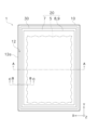
- FIG. 1 is a plan view of an electrolysis cell according to an embodiment.
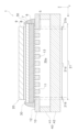
- FIG. 2 is a cross-sectional view taken along line AA of FIG.
- FIG. 3 is a plan view of the opposing surface according to the embodiment.
- FIG. 4 is a cross-sectional view taken along line BB of FIG.
- FIG. 5 is a cross-sectional view taken along the line CC of FIG.
- FIG. 6 is a cross-sectional view of an electrolysis cell according to the first modification.
- FIG. 7 is a cross-sectional view of an electrolysis cell according to the third modification.
- FIG. 1 is a plan view of an electrolysis cell 1 according to an embodiment of the present invention
- Fig. 2 is a cross-sectional view taken along line AA of Fig. 1.
- Electrolytic cell 1 is an example of an "electrochemical cell” according to the present invention. Electrolytic cell 1 is a so-called metal-supported electrolytic cell.
- the electrolytic cell 1 is formed in a plate shape extending in the X-axis and Y-axis directions.
- the electrolytic cell 1 is formed in a rectangular shape extending in the Y-axis direction when viewed in a plan view from the Z-axis direction perpendicular to the X-axis and Y-axis directions.
- the planar shape of the electrolytic cell 1 is not particularly limited, and may be a polygon other than a rectangle, an ellipse, a circle, etc.
- the electrolysis cell 1 includes a metal support 10, a cell body 20, a gas seal 30, and a flow path member 40.
- the metal support 10 supports the cell main body 20.
- the metal support 10 is formed in a plate shape.
- the metal support 10 may be in the shape of a flat plate or a curved plate.
- the metal support 10 only needs to be able to support the cell body 20, and there are no particular limitations on its thickness, but it can be, for example, 0.1 mm or more and 2.0 mm or less.
- the metal support 10 has a plurality of communication holes 11, a first main surface 12, and a second main surface 13.
- Each communication hole 11 penetrates the metal support 10 from the first main surface 12 to the second main surface 13.
- Each communication hole 11 opens to the first main surface 12 and the second main surface 13.
- the opening of each communication hole 11 on the first main surface 12 side is covered by a gas diffusion layer 5 described later.
- the opening of each communication hole 11 on the second main surface 13 side is connected to a flow path 30a described later.
- Each communication hole 11 can be formed by mechanical processing (e.g., punching), laser processing, or chemical processing (e.g., etching).
- each communication hole 11 is formed linearly along the Z-axis direction.
- each communication hole 11 may be inclined with respect to the Z-axis direction, and may not be linear.
- the communication holes 11 may be connected to each other.
- the first main surface 12 is an example of a "main surface” according to the present invention.
- the first main surface 12 is provided on the opposite side of the second main surface 13.
- the cell main body 20 is disposed on the first main surface 12.
- the flow path member 40 is bonded to the second main surface 13.
- the metal support 10 is made of a metal material.
- the metal support 10 is made of an alloy material containing Cr (chromium).
- Examples of such metal materials include Fe-Cr alloy steel (stainless steel, etc.) and Ni-Cr alloy steel.
- Cr content in the metal support 10 can be 4% by mass or more and 30% by mass or less.
- the metal support 10 may contain Ti (titanium) and Zr (zirconium).
- the Ti content in the metal support 10 is not particularly limited, but may be 0.01 mol% or more and 1.0 mol% or less.
- the Al content in the metal support 10 is not particularly limited, but may be 0.01 mol% or more and 0.4 mol% or less.
- the metal support 10 may contain Ti as TiO2 (titania) and Zr as ZrO2 (zirconia).
- the metal support 10 may have an oxide film on its surface that is formed by oxidation of the constituent elements of the metal support 10.
- a typical example of the oxide film is a chromium oxide film.
- the chromium oxide film covers at least a portion of the surface of the metal support 10.
- the chromium oxide film may also cover at least a portion of the inner wall surface of each communication hole 11.
- Cell body 20 The cell body 20 is disposed on the metal support 10. The cell body 20 is supported by the metal support 10.
- the cell main body 20 has an opposing surface 21.
- the opposing surface 21 faces the first main surface 12 of the metal support 10 in the thickness direction.
- the thickness direction is a direction perpendicular to a plane direction parallel to the first main surface 12 of the metal support 10.
- the plane direction is defined by an approximation straight line of the first main surface 12 obtained by the least squares method in a cross section of the metal support 10 along the Z-axis direction.
- two surfaces facing each other means that there is no other member between the two surfaces and the two surfaces are positioned opposite each other, and this concept is not related to whether the two surfaces are joined or parallel.
- the opposing surface 21 includes a bonding region 21a and a non-bonding region 21b.
- the bonding region 21a is a region of the opposing surface 21 that is bonded to the first main surface 12 of the metal support 10.
- the non-bonding region 21b is a region of the opposing surface 21 that is not bonded to the first main surface 12 of the metal support 10.
- two surfaces are bonded means that the two surfaces are in direct contact and that a bonding force exists between the two surfaces.
- two surfaces are not bonded means that no bonding force exists between the two surfaces, and is a concept that is not related to whether the two surfaces are in direct contact or not.
- FIG. 3 is a plan view of the opposing surface 21.
- the non-bonded region 21b is located outside the bonded region 21a. This allows at least a portion of the outer edge of the cell main body 20 to be in a state where it is not restrained by the metal support 10.
- the metal support 10 Conventionally, it has been thought that in order to suppress cracks and breakage in the gas seal portion 30, it is necessary to firmly fix the cell main body 20 to the metal support 10.
- the inventors have gained new knowledge that cracks and breakage in the gas seal portion 30 can be suppressed by deliberately not fixing the outer edge of the cell main body 20 to the metal support 10. Specifically, this is as follows.
- Oxidation-reduction cycles and thermal cycles may cause volume changes in both the metal support 10 and the cell body 20.
- stress is generated in the gas seal 30 due to the difference between the amount of volume change in the metal support 10 and the amount of volume change in the cell body 20.
- the portion of the cell body 20 that is not restrained by the metal support 10 can deform in the planar direction, the stress in the gas seal 30 can be absorbed at that portion.
- cracks and breaks in the gas seal 30 can be suppressed, and the gas sealability of the electrolysis cell 1 can be prevented from deteriorating.
- the bonding region 21a covers all of the communication holes 11 formed in the metal support 10, but some of the communication holes 11 formed in the metal support 10 may not be covered by the bonding region 21a. Therefore, some of the communication holes 11 formed in the metal support 10 may open toward the non-bonding region 21b.
- the non-bonded region 21b preferably surrounds the bonded region 21a.
- the non-bonded region 21b is preferably formed in a ring shape. This allows the entire outer edge of the cell main body 20 to be in a state where it is not restrained by the metal support 10. Therefore, no matter what direction the stress is in, the stress of the gas seal portion 30 can be reliably absorbed. Therefore, cracks and breakage of the gas seal portion 30 can be further suppressed.
- the non-bonded region 21b is separated from the first main surface 12 of the metal support 10. In other words, it is preferable that the non-bonded region 21b is not in direct contact with the first main surface 12 of the metal support 10. As a result, as shown in FIG. 2, a space T1 is provided between the non-bonded region 21b and the first main surface 12, so that the portion of the cell main body 20 that is not restrained by the metal support 10 can also deform in the thickness direction. Therefore, the stress of the gas seal portion 30 can be absorbed more easily, and cracks and breakage of the gas seal portion 30 can be further suppressed.
- FIG. 4 is a cross-sectional view taken along line B-B in FIG. 1.
- FIG. 5 is a cross-sectional view taken along line C-C in FIG. 1.
- FIG. 4 illustrates a first cross-section of the electrolytic cell 1
- FIG. 5 illustrates a second cross-section of the electrolytic cell 1.
- the first and second cross-sections are each perpendicular to the outer edge 12a of the first main surface 12 of the metal support 10 in a plan view of the first main surface 12.
- the first and second cross-sections are adjacent cross-sections in a direction along the outer edge 12a of the first main surface 12.
- two cross-sections being adjacent means that the distance between the two cross-sections in a direction along the outer edge 12a of the first main surface 12 is greater than 0 mm and less than or equal to 5 mm.
- the width W1 of the non-bonded region 21b in the first cross section (FIG. 4) is different from the width W2 of the non-bonded region 21b in the second cross section (FIG. 5). This means that the distance between the outer edge of the bonded region 21a and the gas seal portion 30 is changed. This makes it possible to distribute the stress acting on the outer edge of the bonded region 21a in the planar direction, thereby preventing the bonded region 21a from peeling off from the first main surface 12.
- widths W1 and W2 of the non-bonded region 21b are the sizes of the non-bonded region 21b in the planar direction. It is preferable that the relationship that the width W1 is different from the width W2 holds regardless of the position at which the first and second cross sections are observed, but it is sufficient that there is at least one region where this relationship holds.
- the cell body 20 has a gas diffusion layer 5, a hydrogen electrode layer 6 (cathode), an electrolyte layer 7, a reaction prevention layer 8, and an oxygen electrode layer 9 (anode).
- the gas diffusion layer 5, hydrogen electrode layer 6, electrolyte layer 7, reaction prevention layer 8, and oxygen electrode layer 9 are stacked in this order in the Z-axis direction from the metal support 10 side.
- the hydrogen electrode layer 6, electrolyte layer 7, and oxygen electrode layer 9 are required components, while the gas diffusion layer 5 and reaction prevention layer 8 are optional components.
- the gas diffusion layer 5 is formed on the first main surface 12 of the metal support 10.
- the gas diffusion layer 5 is interposed between the metal support 10 and the hydrogen electrode layer 6. A portion of the gas diffusion layer 5 may extend into each of the communication holes 11 of the metal support 10.
- the gas diffusion layer 5 has the bonding region 21a described above. That is, the bonding region 21a is the region of the surface of the gas diffusion layer 5 that faces the first main surface 12 of the metal support 10.
- the gas diffusion layer 5 is a porous body having gas diffusivity and electrical conductivity.
- the gas diffusion layer 5 supplies the raw gas supplied from each communication hole 11 to the hydrogen electrode layer 6, and discharges the product gas generated in the hydrogen electrode layer 6 to each communication hole 11.
- the gas diffusion layer 5 includes a conductive material.
- the conductive material that can be used include metal materials such as Ni (nickel) and Fe (iron), and conductive ceramic materials.
- the gas diffusion layer 5 may include a substrate supporting a conductive material.
- the substrate may be insulating.
- As the substrate YSZ, CSZ, ScSZ, GDC, SDC, (La, Sr) (Cr, Mn) O 3 , (La, Sr) TiO 3 , Sr 2 (Fe, Mo) 2 O 6 , (La, Sr) VO 3 , (La, Sr) FeO 3 , LDC (lanthanum doped ceria), LSGM (lanthanum gallate), and a mixed material of two or more of these may be used.
- the gas diffusion layer 5 may contain metal elements contained in the metal support 10. This is preferable because it improves the adhesion between the gas diffusion layer 5 and the metal support 10. Note that the conductive material described above is different from the metal elements contained in the metal support 10. Therefore, the conductive material contained in the gas diffusion layer 5 does not need to be contained in the metal support 10.
- the porosity of the gas diffusion layer 5 is not particularly limited, but can be, for example, 20% or more and 40% or less.
- the porosity of the gas diffusion layer 5 is calculated by the following method. First, a cross section of the gas diffusion layer 5 along the Z-axis direction is exposed. Next, a backscattered electron image of the cross section of the gas diffusion layer 5 is obtained at 10,000 times magnification using an SEM device (FE-SEM JSM-7900F, manufactured by JEOL Ltd.). Next, the areas displayed in black in the backscattered electron image (corresponding to pores) are identified using image analysis software Image-Pro manufactured by MEDIACYBERNETICS. The porosity of the gas diffusion layer 5 is then calculated by dividing the total area of the pores by the total area of the backscattered electron images of the gas diffusion layer 5.
- the thickness of the gas diffusion layer 5 is not particularly limited, but can be, for example, 1 ⁇ m or more and 50 ⁇ m or less.
- the method for forming the gas diffusion layer 5 is not particularly limited, and may be a firing method, a spray coating method (thermal spraying, aerosol deposition, aerosol gas deposition, powder jet deposition, particle jet deposition, cold spray, etc.), a PVD method (sputtering, pulsed laser deposition, etc.), a CVD method, etc.
- the hydrogen electrode layer 6 is an example of a "first electrode layer” according to the present invention.
- the hydrogen electrode layer 6 is formed on the gas diffusion layer 5.
- the hydrogen electrode layer 6 is disposed between the gas diffusion layer 5 and the electrolyte layer 7.
- the hydrogen electrode layer 6 has the non-bonded region 21b described above.
- the non-bonded region 21b is a region of the surface of the hydrogen electrode layer 6 that faces the first main surface 12 of the metal support 10.
- a source gas is supplied to the hydrogen electrode layer 6 from each of the communication holes 11 via the gas diffusion layer 5.
- the source gas contains at least H2O .
- the hydrogen electrode layer 6 produces H 2 from the source gas in accordance with the electrochemical reaction of water electrolysis shown in the following formula (1).
- Hydrogen electrode layer 6 H 2 O+2e ⁇ ⁇ H 2 +O 2 ⁇ (1)
- the hydrogen electrode layer 6 produces H 2 , CO, and O 2 ⁇ from the source gas in accordance with the co-electrochemical reactions shown in the following formulas (2), (3), and (4).
- Hydrogen electrode layer 6 CO 2 + H 2 O + 4e ⁇ ⁇ CO + H 2 + 2O 2 ⁇ (2) Electrochemical reaction of H 2 O: H 2 O + 2e ⁇ ⁇ H 2 + O 2 ⁇ (3) Electrochemical reaction of CO2 : CO2 + 2e- ⁇ CO + O2 -... (4)
- the hydrogen electrode layer 6 is a porous body having gas diffusibility and electrical conductivity.
- the raw material gas is supplied to the hydrogen electrode layer 6 from the gas diffusion layer 5.
- the product gas generated in the hydrogen electrode layer 6 is discharged to the gas diffusion layer 5 side.
- the hydrogen electrode layer 6 includes a conductive material.
- a conductive material metal materials such as Ni (nickel) and Fe (iron), conductive ceramic materials, etc. can be used.
- Ni nickel
- Fe iron
- conductive ceramic materials etc.
- Ni also functions as a thermal catalyst that promotes the thermal reaction between the generated H 2 and CO 2 contained in the raw material gas to maintain an appropriate gas composition for methanation, reverse water gas shift reaction, etc.
- the conductive material exists in an oxide state (e.g., NiO) in an oxidizing atmosphere and in a metallic state (e.g., Ni) in a reducing atmosphere.
- an oxide state e.g., NiO
- a metallic state e.g., Ni
- the hydrogen electrode layer 6 includes an oxide ion conductive material such as YSZ, CSZ, ScSZ, GDC, SDC, (La, Sr) (Cr, Mn) O 3 , (La, Sr) TiO 3 , Sr 2 (Fe, Mo) 2 O 6 , (La, Sr) VO 3 , (La, Sr) FeO 3 , LDC, LSGM, or a mixture of two or more of these materials.
- oxide ion conductive material such as YSZ, CSZ, ScSZ, GDC, SDC, (La, Sr) (Cr, Mn) O 3 , (La, Sr) TiO 3 , Sr 2 (Fe, Mo) 2 O 6 , (La, Sr) VO 3 , (La, Sr) FeO 3 , LDC, LSGM, or a mixture of two or more of these materials.
- the hydrogen electrode layer 6 has a single-layer structure made of a single composition, but it may have a multi-layer structure made of different compositions.
- the porosity of the hydrogen electrode layer 6 is not particularly limited, but can be, for example, 20% or more and 40% or less.
- the porosity of the hydrogen electrode layer 6 is calculated by dividing the total area of the pores by the total area of the backscattered electron image of the hydrogen electrode layer 6, similar to the porosity of the gas diffusion layer 5 described above.
- the thickness of the hydrogen electrode layer 6 is not particularly limited, but can be, for example, 1 ⁇ m or more and 500 ⁇ m or less.
- the method for forming the hydrogen electrode layer 6 is not particularly limited, and methods such as firing, spray coating, PVD, and CVD can be used.
- the hydrogen electrode layer 6 can be formed by surrounding the gas diffusion layer 5 with a square-shaped pore-forming material.
- the electrolyte layer 7 is disposed between the hydrogen electrode layer 6 and the oxygen electrode layer 9.
- the reaction prevention layer 8 is disposed between the electrolyte layer 7 and the oxygen electrode layer 9, so that the electrolyte layer 7 is sandwiched between the hydrogen electrode layer 6 and the reaction prevention layer 8.
- the electrolyte layer 7 covers the hydrogen electrode layer 6 and also covers the area of the first main surface 12 of the metal support 10 that is exposed from the gas diffusion layer 5.
- the electrolyte layer 7 transfers O 2- generated in the hydrogen electrode layer 6 to the oxygen electrode layer 9.
- the electrolyte layer 7 is made of a dense material having oxide ion conductivity.
- the electrolyte layer 7 can be made of, for example, YSZ (yttria-stabilized zirconia, e.g., 8YSZ), GDC (gadolinium-doped ceria), ScSZ (scandia-stabilized zirconia), SDC (samarium-doped ceria), LSGM (lanthanum gallate), or the like.
- the porosity of the electrolyte layer 7 is not particularly limited, but can be, for example, 0.1% to 7%.
- the thickness of the electrolyte layer 7 is not particularly limited, but can be, for example, 1 ⁇ m to 100 ⁇ m.
- the method for forming the electrolyte layer 7 is not particularly limited, and methods such as baking, spray coating, PVD, and CVD can be used.
- reaction prevention layer 8 The reaction prevention layer 8 is disposed between the electrolyte layer 7 and the oxygen electrode layer 9. The reaction prevention layer 8 is disposed on the opposite side of the electrolyte layer 7 to the hydrogen electrode layer 6. The reaction prevention layer 8 prevents the constituent elements of the electrolyte layer 7 from reacting with the constituent elements of the oxygen electrode layer 9 to form a layer with high electrical resistance.
- the reaction prevention layer 8 is made of an oxide ion conductive material.
- the reaction prevention layer 8 can be made of GDC, SDC, etc.
- the porosity of the reaction prevention layer 8 is not particularly limited, but can be, for example, 0.1% to 50%.
- the thickness of the reaction prevention layer 8 is not particularly limited, but can be, for example, 1 ⁇ m to 50 ⁇ m.
- the method for forming the reaction prevention layer 8 is not particularly limited, and a baking method, a spray coating method, a PVD method, a CVD method, etc. can be used.
- the oxygen electrode layer 9 is an example of a "second electrode layer” according to the present invention.
- the oxygen electrode layer 9 is disposed on the opposite side of the hydrogen electrode layer 6 with respect to the electrolyte layer 7.
- the reaction prevention layer 8 is disposed between the electrolyte layer 7 and the oxygen electrode layer 9, and therefore the oxygen electrode layer 9 is connected to the reaction prevention layer 8. If the reaction prevention layer 8 is not disposed between the electrolyte layer 7 and the oxygen electrode layer 9, the oxygen electrode layer 9 would be connected to the electrolyte layer 7.
- the oxygen electrode layer 9 produces O 2 from O 2 ⁇ transferred from the hydrogen electrode layer 6 via the electrolyte layer 7 in accordance with the chemical reaction of the following formula (5).
- Oxygen electrode layer 9 2O 2 ⁇ ⁇ O 2 +4e ⁇ (5)
- the oxygen electrode layer 9 is a porous body having oxide ion conductivity and electrical conductivity, and may be made of a composite material of one or more of (La,Sr)(Co,Fe) O3 , (La,Sr) FeO3 , La(Ni,Fe) O3 , (La,Sr) CoO3 , and (Sm,Sr) CoO3 and an oxide ion conductive material (such as GDC).
- the porosity of the oxygen electrode layer 9 is not particularly limited, but can be, for example, 20% or more and 60% or less.
- the thickness of the oxygen electrode layer 9 is not particularly limited, but can be, for example, 1 ⁇ m or more and 100 ⁇ m or less.
- the method for forming the oxygen electrode layer 9 is not particularly limited, and a firing method, a spray coating method, a PVD method, a CVD method, etc. can be used.
- the gas seal part 30 provides a seal between the metal support 10 and the cell main body 20.
- the gas seal part 30 separates the gas on the hydrogen electrode layer 6 side from the gas on the oxygen electrode layer 9 side.
- the gas seal part 30 surrounds the outer periphery of the cell main body 20.
- the gas seal part 30 is connected to the first main surface 12 of the metal support 10 and the electrolyte layer 7 of the cell main body 20.
- the gas seal portion 30 is made of a dense material that is gas impermeable.
- the gas seal portion 30 can be made of, for example, crystallized glass, amorphous glass, spinel oxide, brazing material, or the constituent material of the electrolyte layer 7.
- Crystallized glass is glass in which the ratio of the "volume occupied by the crystalline phase" to the total volume (degree of crystallization) is 60% or more, and the ratio of the "volume occupied by the amorphous phase and impurities" to the total volume is less than 40%. Examples of such crystallized glass include SiO 2 -B 2 O 3 -based, SiO 2 -CaO-based, and SiO 2 -MgO-based.
- the gas seal portion 30 when the gas seal portion 30 is made of the same material as the electrolyte layer 7, the gas seal portion 30 may be substantially integral with the electrolyte layer 7.
- the flow path member 40 is joined to the second main surface 13 of the metal support 10.
- the flow path member 40 forms a flow path 30a between itself and the metal support 10.
- a source gas is supplied to the flow path 30a.
- the source gas supplied to the flow path 30a is supplied to the hydrogen electrode layer 6 of the cell main body 20 through each communication hole 11 of the metal support 10.
- the flow path member 40 can be made of, for example, an alloy material.
- the flow path member 40 may be made of the same material as the metal support 10. In this case, the flow path member 40 may be substantially integral with the metal support 10.
- the flow path member 40 has a frame body 41 and an interconnector 42.
- the frame body 41 is an annular member that surrounds the side of the flow path 30a.
- the frame body 41 is joined to the second main surface 13 of the metal support body 10.
- the interconnector 42 is a plate-shaped member for electrically connecting an external power source or another electrolysis cell in series with the electrolysis cell 1.
- the interconnector 42 is joined to the frame body 41.
- the frame body 41 and the interconnector 42 are separate members, but the frame body 41 and the interconnector 42 may be an integrated member.
- the region of the surface of the gas diffusion layer 5 that faces the first main surface 12 of the metal support 10 is the bonding region 21a, but this is not limited to this.
- the region of the surface of the hydrogen electrode layer 6 that faces the first main surface 12 of the metal support 10 may include both the bonding region 21a and the non-bonding region 21b.
- the space T1 is provided between the non-bonding region 21b and the first main surface 12, but this is not limited to this.
- the space T1 does not need to exist.
- the entire area of the surface of the hydrogen electrode layer 6 that faces the first main surface 12 of the metal support 10 is the non-bonded region 21b, but this is not limited to this.
- the gas seal portion 30 when part of the gas seal portion 30 enters the gap between the metal support 10 and the cell main body 20, only a part of the area of the surface of the hydrogen electrode layer 6 that faces the first main surface 12 of the metal support 10 becomes the non-bonded region 21b.
- the openings of each communication hole 11 on the first main surface 12 side of the metal support 10 are covered by the gas diffusion layer 5, but this is not limited thereto.
- the gas diffusion layer 5 does not have to cover the openings of each communication hole 11 on the first main surface 12 side. In this case, since through holes communicating with each communication hole 11 are formed in the gas diffusion layer 5, gas can be supplied and exhausted more efficiently via the through holes.
- the hydrogen electrode layer 6 functions as a cathode and the oxygen electrode layer 9 functions as an anode, but the arrangement of the hydrogen electrode layer 6 and the oxygen electrode layer 9 may be reversed.
- the electrolysis cell 1 has been described as an example of an electrochemical cell, but the electrochemical cell is not limited to an electrolysis cell.
- An electrochemical cell is a general term for an element in which a pair of electrodes are arranged so that an electromotive force is generated from an overall oxidation-reduction reaction in order to convert electrical energy into chemical energy, and an element for converting chemical energy into electrical energy. Therefore, the electrochemical cell includes, for example, a fuel cell that uses oxide ions or protons as a carrier.
- Electrolysis cell 10
- Metal support 11 Through hole 12
- First main surface 12a
- Second main surface 20
- Cell body 21
- Opposing surface 21a Bonded region 21b
- Non-bonded region T1 Space 5
- Gas diffusion layer 6
- Hydrogen electrode layer 7
- Reaction prevention layer 8
- Oxygen electrode layer 30
- Gas seal portion 40 Flow path member 40a Flow path
Landscapes
- Chemical & Material Sciences (AREA)
- Electrochemistry (AREA)
- Chemical Kinetics & Catalysis (AREA)
- Engineering & Computer Science (AREA)
- Organic Chemistry (AREA)
- Materials Engineering (AREA)
- General Chemical & Material Sciences (AREA)
- Metallurgy (AREA)
- Sustainable Energy (AREA)
- Sustainable Development (AREA)
- Life Sciences & Earth Sciences (AREA)
- Manufacturing & Machinery (AREA)
- Inorganic Chemistry (AREA)
- Electrolytic Production Of Non-Metals, Compounds, Apparatuses Therefor (AREA)
- Fuel Cell (AREA)
Priority Applications (2)
| Application Number | Priority Date | Filing Date | Title |
|---|---|---|---|
| PCT/JP2023/013506 WO2024201988A1 (ja) | 2023-03-31 | 2023-03-31 | 電気化学セル |
| JP2024560889A JP7637833B1 (ja) | 2023-03-31 | 2023-03-31 | 電気化学セル |
Applications Claiming Priority (1)
| Application Number | Priority Date | Filing Date | Title |
|---|---|---|---|
| PCT/JP2023/013506 WO2024201988A1 (ja) | 2023-03-31 | 2023-03-31 | 電気化学セル |
Publications (1)
| Publication Number | Publication Date |
|---|---|
| WO2024201988A1 true WO2024201988A1 (ja) | 2024-10-03 |
Family
ID=92904496
Family Applications (1)
| Application Number | Title | Priority Date | Filing Date |
|---|---|---|---|
| PCT/JP2023/013506 Ceased WO2024201988A1 (ja) | 2023-03-31 | 2023-03-31 | 電気化学セル |
Country Status (2)
| Country | Link |
|---|---|
| JP (1) | JP7637833B1 (https=) |
| WO (1) | WO2024201988A1 (https=) |
Cited By (3)
| Publication number | Priority date | Publication date | Assignee | Title |
|---|---|---|---|---|
| WO2025164665A1 (ja) * | 2024-01-29 | 2025-08-07 | 京セラ株式会社 | 複合部材、電気化学セル、電気化学セル装置、モジュールおよびモジュール収容装置 |
| WO2025164668A1 (ja) * | 2024-01-30 | 2025-08-07 | 京セラ株式会社 | 複合部材、電気化学セル、電気化学セル装置、モジュールおよびモジュール収容装置 |
| WO2026048897A1 (ja) * | 2024-08-27 | 2026-03-05 | 京セラ株式会社 | 電気化学セル、電気化学セル装置、モジュールおよびモジュール収容装置 |
Citations (3)
| Publication number | Priority date | Publication date | Assignee | Title |
|---|---|---|---|---|
| JP2016201283A (ja) * | 2015-04-13 | 2016-12-01 | パナソニックIpマネジメント株式会社 | 燃料電池 |
| JP2020140924A (ja) * | 2019-03-01 | 2020-09-03 | 株式会社デンソー | 固体酸化物形燃料電池セルスタック |
| JP2023003622A (ja) * | 2021-06-24 | 2023-01-17 | 株式会社デンソー | 電気化学セル |
Family Cites Families (1)
| Publication number | Priority date | Publication date | Assignee | Title |
|---|---|---|---|---|
| US20090123784A1 (en) * | 2007-09-13 | 2009-05-14 | Pavlik Thomas J | Fuel cell module |
-
2023
- 2023-03-31 WO PCT/JP2023/013506 patent/WO2024201988A1/ja not_active Ceased
- 2023-03-31 JP JP2024560889A patent/JP7637833B1/ja active Active
Patent Citations (3)
| Publication number | Priority date | Publication date | Assignee | Title |
|---|---|---|---|---|
| JP2016201283A (ja) * | 2015-04-13 | 2016-12-01 | パナソニックIpマネジメント株式会社 | 燃料電池 |
| JP2020140924A (ja) * | 2019-03-01 | 2020-09-03 | 株式会社デンソー | 固体酸化物形燃料電池セルスタック |
| JP2023003622A (ja) * | 2021-06-24 | 2023-01-17 | 株式会社デンソー | 電気化学セル |
Cited By (3)
| Publication number | Priority date | Publication date | Assignee | Title |
|---|---|---|---|---|
| WO2025164665A1 (ja) * | 2024-01-29 | 2025-08-07 | 京セラ株式会社 | 複合部材、電気化学セル、電気化学セル装置、モジュールおよびモジュール収容装置 |
| WO2025164668A1 (ja) * | 2024-01-30 | 2025-08-07 | 京セラ株式会社 | 複合部材、電気化学セル、電気化学セル装置、モジュールおよびモジュール収容装置 |
| WO2026048897A1 (ja) * | 2024-08-27 | 2026-03-05 | 京セラ株式会社 | 電気化学セル、電気化学セル装置、モジュールおよびモジュール収容装置 |
Also Published As
| Publication number | Publication date |
|---|---|
| JP7637833B1 (ja) | 2025-02-28 |
| JPWO2024201988A1 (https=) | 2024-10-03 |
Similar Documents
| Publication | Publication Date | Title |
|---|---|---|
| JP7637833B1 (ja) | 電気化学セル | |
| US20240332566A1 (en) | Electrochemical cell | |
| US20240332565A1 (en) | Electrochemical cell | |
| JP7280991B1 (ja) | 電気化学セル | |
| WO2024101163A1 (ja) | 電気化学セル | |
| US20240328006A1 (en) | Electrochemical cell | |
| JP7657379B1 (ja) | 電気化学セル | |
| JP7659705B1 (ja) | 電気化学セル | |
| JP7577244B2 (ja) | 電気化学セル | |
| US20250300194A1 (en) | Inter-connector and electrochemical cell | |
| JP7698795B2 (ja) | 電気化学セル | |
| JP7625134B2 (ja) | 電気化学セル | |
| JP7604715B2 (ja) | 電気化学セル | |
| US20250118859A1 (en) | Reducing gas container and metal-supported electrochemical cell | |
| US20250116011A1 (en) | Fluid container and electrochemical cell | |
| JP7649929B2 (ja) | 電気化学セル | |
| JP7649810B2 (ja) | 電気化学セル | |
| JP7659706B1 (ja) | 電気化学セル | |
| US20250297376A1 (en) | Inter-connector and electrochemical cell | |
| US20250118777A1 (en) | Chromium alloy container and metal-supported electrochemical cell | |
| US20250116013A1 (en) | Chromium alloy container and metal-supported electrochemical cell | |
| WO2025141900A1 (ja) | 電気化学セル | |
| WO2024201997A1 (ja) | 電気化学セル | |
| WO2025074569A1 (ja) | 流体容器及び電気化学セル | |
| WO2025104825A1 (ja) | 電気化学セル |
Legal Events
| Date | Code | Title | Description |
|---|---|---|---|
| WWE | Wipo information: entry into national phase |
Ref document number: 2024560889 Country of ref document: JP |
|
| 121 | Ep: the epo has been informed by wipo that ep was designated in this application |
Ref document number: 23930623 Country of ref document: EP Kind code of ref document: A1 |
|
| NENP | Non-entry into the national phase |
Ref country code: DE |
|
| 122 | Ep: pct application non-entry in european phase |
Ref document number: 23930623 Country of ref document: EP Kind code of ref document: A1 |