WO2024201987A1 - 可変ノズル装置、および可変容量型排気ターボ過給機 - Google Patents
可変ノズル装置、および可変容量型排気ターボ過給機 Download PDFInfo
- Publication number
- WO2024201987A1 WO2024201987A1 PCT/JP2023/013505 JP2023013505W WO2024201987A1 WO 2024201987 A1 WO2024201987 A1 WO 2024201987A1 JP 2023013505 W JP2023013505 W JP 2023013505W WO 2024201987 A1 WO2024201987 A1 WO 2024201987A1
- Authority
- WO
- WIPO (PCT)
- Prior art keywords
- nozzle
- mount
- variable
- flow path
- recess
- Prior art date
- Legal status (The legal status is an assumption and is not a legal conclusion. Google has not performed a legal analysis and makes no representation as to the accuracy of the status listed.)
- Ceased
Links
Images




Classifications
-
- F—MECHANICAL ENGINEERING; LIGHTING; HEATING; WEAPONS; BLASTING
- F01—MACHINES OR ENGINES IN GENERAL; ENGINE PLANTS IN GENERAL; STEAM ENGINES
- F01D—NON-POSITIVE DISPLACEMENT MACHINES OR ENGINES, e.g. STEAM TURBINES
- F01D25/00—Component parts, details, or accessories, not provided for in, or of interest apart from, other groups
- F01D25/24—Casings; Casing parts, e.g. diaphragms, casing fastenings
- F01D25/246—Fastening of diaphragms or stator-rings
-
- F—MECHANICAL ENGINEERING; LIGHTING; HEATING; WEAPONS; BLASTING
- F01—MACHINES OR ENGINES IN GENERAL; ENGINE PLANTS IN GENERAL; STEAM ENGINES
- F01D—NON-POSITIVE DISPLACEMENT MACHINES OR ENGINES, e.g. STEAM TURBINES
- F01D17/00—Regulating or controlling by varying flow
- F01D17/10—Final actuators
- F01D17/12—Final actuators arranged in stator parts
- F01D17/14—Final actuators arranged in stator parts varying effective cross-sectional area of nozzles or guide conduits
- F01D17/16—Final actuators arranged in stator parts varying effective cross-sectional area of nozzles or guide conduits by means of nozzle vanes
- F01D17/165—Final actuators arranged in stator parts varying effective cross-sectional area of nozzles or guide conduits by means of nozzle vanes for radial flow, i.e. the vanes turning around axes which are essentially parallel to the rotor centre line
-
- F—MECHANICAL ENGINEERING; LIGHTING; HEATING; WEAPONS; BLASTING
- F05—INDEXING SCHEMES RELATING TO ENGINES OR PUMPS IN VARIOUS SUBCLASSES OF CLASSES F01-F04
- F05D—INDEXING SCHEME FOR ASPECTS RELATING TO NON-POSITIVE-DISPLACEMENT MACHINES OR ENGINES, GAS-TURBINES OR JET-PROPULSION PLANTS
- F05D2250/00—Geometry
- F05D2250/20—Three-dimensional
- F05D2250/27—Three-dimensional hyperboloid
-
- F—MECHANICAL ENGINEERING; LIGHTING; HEATING; WEAPONS; BLASTING
- F05—INDEXING SCHEMES RELATING TO ENGINES OR PUMPS IN VARIOUS SUBCLASSES OF CLASSES F01-F04
- F05D—INDEXING SCHEME FOR ASPECTS RELATING TO NON-POSITIVE-DISPLACEMENT MACHINES OR ENGINES, GAS-TURBINES OR JET-PROPULSION PLANTS
- F05D2250/00—Geometry
- F05D2250/20—Three-dimensional
- F05D2250/29—Three-dimensional machined; miscellaneous
- F05D2250/293—Three-dimensional machined; miscellaneous lathed, e.g. rotation symmetrical
-
- F—MECHANICAL ENGINEERING; LIGHTING; HEATING; WEAPONS; BLASTING
- F05—INDEXING SCHEMES RELATING TO ENGINES OR PUMPS IN VARIOUS SUBCLASSES OF CLASSES F01-F04
- F05D—INDEXING SCHEME FOR ASPECTS RELATING TO NON-POSITIVE-DISPLACEMENT MACHINES OR ENGINES, GAS-TURBINES OR JET-PROPULSION PLANTS
- F05D2250/00—Geometry
- F05D2250/20—Three-dimensional
- F05D2250/29—Three-dimensional machined; miscellaneous
- F05D2250/294—Three-dimensional machined; miscellaneous grooved
-
- Y—GENERAL TAGGING OF NEW TECHNOLOGICAL DEVELOPMENTS; GENERAL TAGGING OF CROSS-SECTIONAL TECHNOLOGIES SPANNING OVER SEVERAL SECTIONS OF THE IPC; TECHNICAL SUBJECTS COVERED BY FORMER USPC CROSS-REFERENCE ART COLLECTIONS [XRACs] AND DIGESTS
- Y02—TECHNOLOGIES OR APPLICATIONS FOR MITIGATION OR ADAPTATION AGAINST CLIMATE CHANGE
- Y02T—CLIMATE CHANGE MITIGATION TECHNOLOGIES RELATED TO TRANSPORTATION
- Y02T10/00—Road transport of goods or passengers
- Y02T10/10—Internal combustion engine [ICE] based vehicles
- Y02T10/12—Improving ICE efficiencies
Definitions
- This disclosure relates to a variable nozzle device and a variable displacement exhaust turbocharger equipped with this variable nozzle device.
- variable displacement exhaust turbochargers have been known as exhaust turbochargers that use the energy of the engine's exhaust gas to supercharge the engine's intake air (see, for example, Patent Document 1).
- Variable displacement exhaust turbochargers use a variable nozzle device to adjust the cross-sectional area of the nozzle flow passage that sends exhaust gas from the scroll flow passage of the turbine housing to the turbine wheel, thereby changing the flow speed and pressure of the exhaust gas sent to the turbine wheel and enhancing the supercharging effect.
- Patent Document 1 discloses that a rod-shaped nozzle support supports the nozzle mount and nozzle plate in a spaced-apart state, and that the body portion of the nozzle support located in the nozzle flow path has a small diameter portion in the center in the extension direction of the nozzle support, and large diameter portions at both ends that are larger than the small diameter portion.
- the nozzle support has a body portion with such a shape at both ends, it may distort the flow of exhaust gas that collides with the nozzle vanes, which may increase the cost of the actuator that rotates the nozzle vanes and increase the load on the link system (e.g., drive ring and vane lever) that transmits the actuator drive to the nozzle vanes.
- the link system e.g., drive ring and vane lever
- the present disclosure has been made in consideration of the above-mentioned problems, and aims to provide a variable nozzle device equipped with a nozzle support having a body portion with thickened ends, capable of suppressing distortion of the flow of exhaust gas colliding with the nozzle vanes.
- variable nozzle device comprises a nozzle mount, a nozzle plate that defines a nozzle flow path between the nozzle mount and the nozzle plate, a rod-shaped nozzle support that connects the nozzle mount and the nozzle plate, the nozzle support including a pair of large diameter portions at both ends in the extension direction of a body portion located between the nozzle mount and the nozzle plate, the diameter of which is larger than that of the central portion of the body portion, and a nozzle vane that is rotatably supported by at least one of the nozzle mount and the nozzle plate and is located downstream of the nozzle flow path from the nozzle support, and the nozzle mount has a recess formed in the flow path surface facing the nozzle flow path, and at least a portion of one of the pair of large diameter portions is accommodated in the recess.
- variable nozzle device disclosed herein can suppress distortion of the flow of exhaust gas colliding with the nozzle vanes when equipped with a nozzle support having a body portion with thickened ends.
- FIG. 1 is a diagram illustrating a schematic configuration of a turbocharger including a variable nozzle device according to some embodiments.
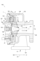
- FIG. 2 is a vertical cross-sectional view showing an example of a configuration of a turbine side of a turbocharger.
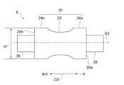
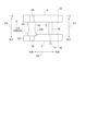
- 3A and 3B are diagrams illustrating a schematic configuration of a nozzle support according to the first embodiment.
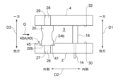
- 3 is a diagram illustrating a schematic configuration of a nozzle support and the periphery of the nozzle support according to the first embodiment.
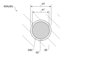
- FIG. 4A to 4C are diagrams for explaining the configuration of a countersunk hole according to the first embodiment.
- 1A to 1C are diagrams illustrating schematic configurations of a nozzle support and the periphery of the nozzle support according to some embodiments.
- FIG. 13 is a diagram illustrating a schematic configuration of a nozzle support and the periphery of the nozzle support according to a second embodiment.
- FIG. 13A and 13B are diagrams for explaining the configuration of a cutout according to a second embodiment.
- 1A and 1B are diagrams illustrating a configuration of a notch according to an embodiment.
- 13A and 13B are diagrams illustrating a configuration of a notch according to another embodiment.
- variable nozzle device according to an embodiment of the present disclosure will be described with reference to the drawings.
- This embodiment shows one aspect of the present disclosure and does not limit the disclosure, and can be modified as desired within the scope of the technical concept of the present disclosure.
- FIG. 1 is a diagram that shows a schematic configuration of a turbocharger 100 equipped with a variable nozzle device 1 according to some embodiments.
- the turbocharger 100 includes a turbine 102, a compressor 104, a rotating shaft 106 that connects the turbine 102 and the compressor 104, and the variable nozzle device 1.
- the turbine 102 is driven to rotate by, for example, exhaust gas G discharged from the engine 200.
- the power of the turbine 102 is transmitted to the compressor 104 via a rotating shaft 106, and the compressor 104 compresses the intake air A supplied to the engine 200.
- the turbine 102 is provided with a variable nozzle device 1 for changing the flow speed and pressure of the exhaust gas G supplied to the turbine 102.
- Such a supercharger 100 is a so-called variable capacity exhaust turbo supercharger.
- the supercharger 100 is mounted, for example, on a passenger car.
- Figure 2 is a vertical cross-sectional view showing an example of the configuration of the turbine 102 side of the turbocharger 100.
- the turbine 102 includes a turbine wheel 120 provided on one side of the rotating shaft 106, and a turbine housing 122 that houses the turbine wheel 120.
- the direction in which the axis O1 of the rotating shaft 106 extends is referred to as the axial direction D1
- the direction from the compressor 104 toward the turbine 102 is referred to as one side of the axial direction D1
- the direction from the turbine 102 toward the compressor 104 is referred to as the other side of the axial direction D1.
- the direction perpendicular to the axis O1 is referred to as the radial direction D2
- the direction of the radial direction D2 that approaches the axis O1 is referred to as the inner side of the radial direction D2
- the direction that moves away from the axis O1 is referred to as the outer side of the radial direction D2.
- the turbine housing 122 has an inlet 124 for introducing exhaust gas G into the interior, and an outlet 126 for discharging the exhaust gas G that has passed through the turbine wheel 120 to the outside.
- a scroll passage 128 for guiding the exhaust gas G introduced through the inlet 124 to the turbine wheel 120, and an exhaust passage 130 for discharging the exhaust gas G that has passed through the turbine wheel 120 through the outlet 126 are formed inside the turbine housing 122.
- the scroll passage 128 is located on the outer periphery side of the turbine wheel 120. In other words, the scroll passage 128 is located outside the turbine wheel 120 in the radial direction D2.
- the exhaust passage 130 extends along the axial direction D1 and includes the outlet 126 at one end on one side of the axial direction D1.
- the exhaust passage 130 is located inside the scroll passage 128 in the radial direction D2.
- variable nozzle device 1 includes a nozzle mount 2, a nozzle plate 4, a nozzle support 6, and a nozzle vane 8.
- the variable nozzle device 1 further includes a vane lever 10, a drive ring 12, and an actuator 15.
- the nozzle mount 2 has a circular ring shape and a plate shape. In the embodiment shown in FIG. 2, the nozzle mount 2 is fixed to a bearing housing 134 that houses a bearing 132 that rotatably supports the rotating shaft 106. The nozzle mount 2 is sandwiched between the bearing housing 134 and the turbine housing 122.
- the nozzle plate 4 defines a nozzle flow passage 3 between itself and the nozzle mount 2.
- the nozzle plate 4 has a circular ring shape and a plate shape.
- the nozzle plate 4 is located on one side of the nozzle mount 2 in the axial direction D1.
- the nozzle flow passage 3 communicates with the scroll flow passage 128, and guides the exhaust gas G from the scroll flow passage 128 to the turbine wheel 120.
- the nozzle support 6 will be explained later.
- the nozzle vane 8 is located downstream of the nozzle flow path 3 from the nozzle support 6. In other words, the nozzle vane 8 is located inside the nozzle support 6 in the radial direction D2 of the nozzle flow path 3.
- the nozzle vane 8 is rotatably supported by at least one of the nozzle mount 2 and the nozzle plate 4.
- the nozzle vane 8 includes a vane shaft 14 inserted into a hole 18 formed in the nozzle mount 2, and a vane blade 16 arranged in the nozzle flow path 3.
- the hole 18 penetrates the nozzle mount 2 along the axial direction D1.
- the vane shaft 14 is inserted into this hole 18, so that the nozzle vane 8 is rotatably supported by the nozzle mount 2.
- the nozzle vane 8 is supported by the nozzle mount 2 from the other side in the axial direction D1.
- This nozzle vane 8 is not supported from one side in the axial direction D1, but is supported by the nozzle mount 2 in a cantilever manner.
- the variable nozzle device 1 includes a plurality of nozzle vanes 8 arranged at intervals from each other along the circumferential direction of the rotating shaft 106. Although not illustrated, in some embodiments, the nozzle vane 8 is supported by both the nozzle mount 2 and the nozzle plate 4.
- the vane blades 16 are provided on one side of the axial direction D1 of the vane shaft 14, and rotate around the rotation axis O2 of the vane shaft 14.
- the vane blades 16 rotate, the flow passage cross-sectional area of the nozzle flow passage 3 increases or decreases, and the flow speed and pressure of the exhaust gas G guided to the turbine wheel 120 change.
- the variable nozzle device 1 is capable of controlling the supercharging pressure of the turbine 102.
- the rotation axis O2 extends along the axial direction D1.
- the axis O1 and the rotation axis O2 are parallel to each other.
- the vane lever 10 is a rod-shaped member extending along the radial direction D2.
- the vane lever 10 has an inner part 10a on the inside in the radial direction D2 fixed to the other side of the vane shaft 14 in the axial direction D1.
- the vane lever 10 has an outer part 10b on the outside in the radial direction D2 mechanically connected to the drive ring 12. Specifically, the outer part 10b of the vane lever 10 is fitted into a fitting hole 19 formed in the drive ring 12.
- the drive ring 12 has an annular shape and is configured to be rotatable along the circumferential direction of the rotating shaft 106 relative to the nozzle mount 2.
- the drive ring 12 is connected to the actuator 15 via a rod-shaped drive shaft 21.
- the actuator 15 rotates the drive ring 12 via the drive shaft 21.
- the actuator 15 includes, for example, an electric motor or an air cylinder.
- the variable nozzle device 1 is configured such that the drive of the actuator 15 is transmitted to the nozzle vane 8 via the drive shaft 21, the drive ring 12, and the vane lever 10, causing the vane blades 16 to rotate.
- the variable nozzle device 1 further includes a control device electrically connected to the actuator 15. The control device is configured to control the drive of the actuator 15 based on, for example, the rotation speed of the engine 200.
- Figure 3 is a diagram that shows a schematic configuration of the nozzle support 6 according to the first embodiment.
- Figure 4 is a diagram that shows a schematic configuration of the nozzle support 6 and the area around the nozzle support 6 according to the first embodiment.
- the nozzle support 6 has a rod shape.
- the nozzle support 6 has a cylindrical shape. And, as shown in FIG. 4, this nozzle support 6 connects the nozzle mount 2 and the nozzle plate 4.
- the direction in which the nozzle support 6 extends is referred to as extension direction D3, the direction from the nozzle mount 2 toward the nozzle plate 4 is referred to as one side of the extension direction D3, and the direction from the nozzle plate 4 toward the nozzle mount 2 is referred to as the other side of the extension direction D3.
- the nozzle support 6 extends along the axial direction D1.
- the extension direction D3 and the axial direction D1 are parallel to each other.
- the nozzle support 6 includes a body portion 20, a nozzle mount connecting portion 26, and a nozzle plate connecting portion 28.
- Each of the body portion 20, the nozzle mount connecting portion 26, and the nozzle plate connecting portion 28 that constitute the nozzle support 6 may be integrally configured as a single part.
- the body portion 20 is located between the nozzle mount 2 and the nozzle plate 4. As shown in FIG. 3, the body portion 20 includes a central portion 23 and a pair of large diameter portions 24a, 24b. In the embodiment shown in FIG. 3, the central portion 23 is curved concavely toward the center line O3 of the nozzle support 6 so that the external shape changes smoothly.
- One large diameter portion 24a includes one end on one side of the extension direction D3 of the body portion 20.
- the other large diameter portion 24b includes the other end on the other side of the extension direction D3 of the body portion 20.
- One large diameter portion 24a is located on the opposite side of the other large diameter portion 24b in the extension direction D3, sandwiching the central portion 23 therebetween.
- Each of the pair of large diameter portions 24a, 24b has a larger diameter than the central portion 23.
- each of the pair of large diameter portions 24a, 24b has the same diameter as each other.
- Each of the pair of large diameter portions 24a, 24b has the same outer diameter ⁇ 1 at any position in the extension direction D3.
- each of the pair of large diameter portions 24a, 24b is configured to have a larger diameter than the central portion 23.
- at least one of the pair of large diameter portions 24a, 24b includes a tapered surface in which the outer diameter ⁇ 1 increases or decreases toward one side or the other side of the extension direction D3.
- one large diameter portion 24a and the other large diameter portion 24b have outer diameters ⁇ 1 that are different from each other.
- the nozzle mount connecting portion 26 is connected to the other end face 20b on the other side of the extension direction D3 of the body portion 20.
- the nozzle plate connecting portion 28 is connected to one end face 20a on one side of the extension direction D3 of the body portion 20.
- the nozzle plate connecting portion 28 is fitted into a plate side fitting hole 29 formed in the plate side flow path surface 32 on the nozzle flow path 3 side of the nozzle plate 4.
- the plate side fitting hole 29 penetrates the nozzle plate 4 along the axial direction D1.
- the nozzle mount 2 has a recess 40 recessed from the mount-side flow path surface 30 facing the nozzle flow path 3.
- the bottom surface 41 of the recess 40 has a mount-side fitting hole 27 into which the nozzle mount connecting part 26 is fitted.
- the mount-side fitting hole 27 penetrates the nozzle mount 2 along the axial direction D1.
- the recess 40 is recessed from the mount side flow path surface 30 so as to be shallower than the length of the other large diameter portion 24 in the extension direction D3.
- the bottom surface 41 of the recess 40 is in contact with the other end surface 20b of the body portion 20.
- the entirety of the other large diameter portion 24b is accommodated in the recess 40. Note that in the present disclosure, the space of the recess 40 in which a portion of the other large diameter portion 24b is accommodated (hereinafter referred to as the accommodation space 45) is not included in the nozzle flow path 3.
- the recess 40 includes a countersunk hole 40A (40) that surrounds the entire circumferential direction of the other large diameter portion 24b.
- FIG. 5 is a diagram for explaining the configuration of the countersunk hole 40A according to the first embodiment, in which the nozzle mount 2 is viewed from the plate thickness direction (axial direction D1). In this disclosure, the plate thickness direction of the nozzle mount 2 is the same direction as the axial direction D1.
- the cross-sectional shape of the countersunk hole 40A is circular. Therefore, as shown in FIG. 5, the opening 42 of the countersunk hole 40A has a circular shape.
- the outer diameter ⁇ 1 of the other large diameter portion 24b is smaller than the inner diameter ⁇ 2 of the countersunk hole 40A.
- the outer diameter ⁇ 1 is approximately the same as the inner diameter ⁇ 2, and satisfies, for example, ⁇ 1> ⁇ 2 ⁇ 0.9.
- the present disclosure does not limit the cross-sectional shape of the countersunk hole 40A to a circular shape.
- the cross-sectional shape of the countersunk hole 40A is rectangular or elliptical.
- the countersunk hole 40A and the pair of large diameter portions 24b have cross-sectional shapes that are similar to each other.
- the body portion 20 of the nozzle support 6 includes a central portion 23 and a pair of large diameter portions 24a, 24b, which prevents the bending rigidity of the nozzle support 6 from decreasing. Furthermore, the nozzle support 6 includes a central portion 23, which reduces the thermal capacity of the nozzle support 6 and increases the heating rate of the nozzle support 6 at high temperatures.
- the difference in the amount of thermal expansion between the nozzle support 6 and the vane blade 16 during transient heating can be reduced, which prevents malfunction of the variable nozzle device 1 caused by narrowing of the gap between the vane blade 16 and the nozzle plate 4 or contact of the vane blade 16 with the nozzle plate 4.
- the nozzle support 6 includes a body portion 20 having a pair of large diameter portions 24a, 24b (the body portion 20 has a shape in which both ends are thickened, and the pair of large diameter portions 24a, 24b have a significant effect on the flow of exhaust gas G passing through the nozzle flow path 3. This distorts the flow of exhaust gas G that collides with the vane blades 16, which may lead to increased costs for the actuator 15 that rotates the nozzle vanes 8 and increased load on the link system (e.g., drive ring 12 and vane lever 10) that transmits the drive of the actuator 15 to the nozzle vane 8.
- the link system e.g., drive ring 12 and vane lever
- variable nozzle device 1 in response to such concerns, a portion of the other large diameter portion 24b is housed in the recess 40, thereby suppressing the effect on the flow of exhaust gas G passing through the nozzle flow path 3. Therefore, in the case of a nozzle support 6 having a body portion 20 with both ends thickened as shown in FIG. 3, it is possible to suppress distortion of the flow of exhaust gas G colliding with the vane blades 16.
- the recess 40 includes a countersunk hole 40A, so that the entire circumferential portion of a portion of the other large diameter portion 24b is accommodated in the countersunk hole 40A, and the influence on the flow of exhaust gas G flowing through the nozzle flow path 3 can be effectively suppressed.
- the outer diameter ⁇ 1 of the other large diameter portion 24b is approximately the same as the inner diameter ⁇ 2 of the countersunk hole 40A, so that most of the accommodation space 45 can be filled by the other large diameter portion 24b. Therefore, the influence of the accommodation space 45 on the flow of exhaust gas G flowing through the nozzle flow path 3 can be suppressed.
- FIG. 6 is a schematic diagram showing the configuration of the nozzle support 6 and the periphery of the nozzle support 6 according to some embodiments.
- the nozzle plate 4 is formed with a second recess 50 recessed from the plate-side flow path surface 32.
- the bottom surface 51 of the second recess 50 is formed with a mount-side fitting hole 27 into which the nozzle plate connection part 28 is fitted.
- the second recess 50 is recessed from the plate-side flow path surface 32 so as to be shallower than the length of the one of the large diameter portions 24a in the extension direction D3.
- the bottom surface 51 of the second recess 50 is in contact with one end surface 20a of the body portion 20.
- the entire one of the large diameter portions 24a is accommodated in the second recess 50.
- the space of the second recess 50 is not included in the nozzle flow path 3.
- a portion of the pair of large diameter portions 24a is housed in the second recess 50, further reducing the effect on the flow of exhaust gas G passing through the nozzle flow passage 3. Therefore, in the case of a nozzle support 6 having a body portion 20 with both ends being thickened, it is possible to further reduce distortion of the flow of exhaust gas G colliding with the vane blades 16.
- variable nozzle device 1 according to a second embodiment of the present disclosure will be described.
- the variable nozzle device 1 according to the second embodiment differs from the first embodiment in that the recess 40 includes a notch 40B.
- the same components as those in the first embodiment are given the same reference numerals, and detailed descriptions thereof will be omitted.
- FIG. 7 is a diagram that shows a schematic configuration of the nozzle support 6 and the periphery of the nozzle support 6 according to the second embodiment.
- the recess 40 includes a notch 40B (40) that is recessed from the mount-side flow path surface 30 so as to include the outer peripheral edge 60 of the nozzle mount 2.
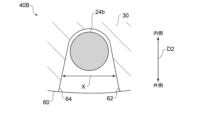
- FIG. 8 is a diagram for explaining the configuration of the notch 40B according to the second embodiment, with the nozzle mount 2 viewed from the plate thickness direction.
- the notch 4B includes a first side surface 62 that faces the accommodation space 45 from one side in the circumferential direction of the nozzle mount 2 (hereinafter referred to as the circumferential direction D4), and a second side surface 64 that faces the accommodation space 45 from the other side of the circumferential direction D4.
- the center of the nozzle mount 2 is located on the axis O1 of the rotating shaft 106.
- One side of the circumferential direction D4 is the upstream side in the rotational direction of the rotating shaft 106, and the other side of the circumferential direction D4 is the downstream side in the rotational direction of the rotating shaft 106.
- the notch 4B includes a connection surface 66 that connects the first side surface 62 and the second side surface 64.
- Each of the first side surface 62 and the second side surface 64 extends linearly.
- the connection surface 66 is concavely curved toward the inside in the radial direction D2.
- the storage space 45 is surrounded by the bottom surface 41, the first side surface 62, the second side surface 64, and the connection surface 66.
- at least one of the first side surface 62 and the second side surface 64 extends along a logarithmic spiral shape.
- a first straight line L1 passes through the axis O1 of the rotating shaft 106 and the center line O3 of the nozzle support 6.
- a second straight line L2 passes through the center line O3 of the nozzle support 6 and the center O4 between the outer end 63 of the first side surface 62 in the radial direction D2 and the outer end 65 of the second side surface 64 in the radial direction D2.
- the included angle ⁇ formed by the first straight line L1 and the second straight line L2 is 45 degrees or more. In the second embodiment, the angle ⁇ is 60 degrees or more and 75 degrees or less.
- variable nozzle device 1 according to the second embodiment, by applying the cutout 40B, it is easier to form the recess 40 in the nozzle mount 2 compared to the case where the countersunk hole 40A is applied.
- variable nozzle device 1 When the variable nozzle device 1 is mounted on a turbocharger 100 (variable displacement exhaust turbocharger), exhaust gas G swirling in the scroll passage 128 flows into the nozzle passage 3.
- the notch 40B by satisfying the angle ⁇ of 45 degrees or more, the notch 40B extends along the radial direction D2 so as to follow the flow of exhaust gas G flowing through the nozzle passage 3, so that the effect of the notch 40B on the flow of exhaust gas G flowing through the nozzle passage 3 can be suppressed.
- the exhaust gas G swirling in the scroll passage 128 flows into the nozzle passage 3 when the flow angle ⁇ 2, defined by the tangent L3 at the inlet of the nozzle passage 3 and the direction of the flow of exhaust gas G, is in the range of 15 degrees or more and 30 degrees or less (see FIG. 8). Therefore, by setting the angle ⁇ to 60 degrees or more and 75 degrees or less, the notch 40B extends along the flow of the exhaust gas G flowing into the nozzle flow path 3 at a flow angle ⁇ 2, effectively suppressing the effect of the notch 40B on the flow of the exhaust gas G flowing through the nozzle flow path 3.
- FIG. 9 is a diagram for explaining the configuration of the notch 40B according to one embodiment.
- FIG. 10 is a diagram for explaining the configuration of the notch 40B according to another embodiment.
- the distance X between the first side 62 and the second side 64 is constant.
- the first side 62 and the second side 64 are spaced apart from each other as they move outward in the radial direction D2. That is, the distance X increases as they move outward in the radial direction D2.
- the recess 40 is a countersunk hole 40A
- a vortex may be formed by the gap between the inner peripheral surface of the countersunk hole 40A and the outer peripheral surface of the other large diameter portion 24b, and this vortex may affect the flow (main flow) of the exhaust gas G flowing through the nozzle flow path 3.
- the recess 40 is a notch 40B, which can inhibit the formation of a vortex. Furthermore, according to the configuration illustrated in FIG. 10, the influence of a stagnation point formed outside (upstream) the nozzle support 6 in the radial direction D2 of the nozzle flow path 3 can be suppressed, and the change in the flow of the exhaust gas G around the nozzle support 6 can be reduced.
- the second recess 50 includes a second notch recessed from the plate-side flow path surface 32 to include the outer peripheral edge of the nozzle plate 4.
- a variable nozzle device (1) according to the present disclosure, A nozzle mount (2); a nozzle plate (4) defining a nozzle flow path (3) between the nozzle mount and the nozzle plate (4); a nozzle support (6) having a rod shape connecting the nozzle mount and the nozzle plate, the nozzle support including a pair of large diameter portions (24a, 24b) having a larger diameter than a central portion (23) of the body portion (20) at both ends in an extension direction (D3) of the body portion (20) located between the nozzle mount and the nozzle plate; a nozzle vane (8) rotatably supported by at least one of the nozzle mount and the nozzle plate and positioned downstream of the nozzle support in the nozzle flow path;
- the nozzle mount has a recess (40) recessed from a flow path surface (30) facing the nozzle flow path, At least a portion of one of the pair of large diameter portions (24b) is housed in the recess.
- the nozzle support When the nozzle support includes a body portion having a pair of large diameter portions (the body portion has a shape in which both ends are thickened), the pair of large diameter portions will have a significant effect on the flow of fluid (exhaust gas) passing through the nozzle flow passage.
- the pair of large diameter portions According to the configuration described in [1] above, at least a portion of one of the pair of large diameter portions is housed in the recess, so that the effect on the flow of fluid passing through the nozzle flow passage is suppressed. Therefore, when a nozzle support is provided with a body portion having a shape in which both ends are thickened, it is possible to suppress distortion of the flow of exhaust gas colliding with the nozzle vane.
- the recess in the configuration described in [1] above, includes a countersunk hole (40A) that surrounds the entire circumferential direction of the large diameter portion.
- At least a portion of the large diameter portion is entirely housed in the recess in the circumferential direction, so that the effect on the flow of the fluid passing through the nozzle flow path can be effectively suppressed.
- the nozzle mount has an annular shape;
- the recess includes a notch (40B) recessed from the flow path surface of the nozzle mount so as to include an outer peripheral edge (60) of the nozzle mount.
- the notch in the configuration described in [3] above, includes a first side surface (62) facing a housing space (45) in which at least a part of the large diameter portion is housed from one circumferential side of the nozzle mount, and a second side surface (64) facing the housing space from the other circumferential side, The first side and the second side are spaced apart from each other radially outwardly of the nozzle mount.
- the nozzle mount is fixed to a bearing housing (134) that accommodates a bearing (132) that rotatably supports a rotating shaft (106), the notch extends toward an upstream side in a rotation direction of the rotary shaft as it moves toward an outer side in the radial direction,
- a bearing housing (134) that accommodates a bearing (132) that rotatably supports a rotating shaft (106)
- the notch extends toward an upstream side in a rotation direction of the rotary shaft as it moves toward an outer side in the radial direction
- an angle ( ⁇ ) formed by a first line (L1) passing through each of the axis (O1) of the rotation shaft and the center of the nozzle support, and a second line (L2) passing through each of the centers of the nozzle support and between the radially outer end of the first side surface and the radially outer end of the second side surface is 45 degrees or more.
- the fluid swirling in the scroll passage flows into the nozzle passage.
- the recess extends so as to follow the flow of the fluid flowing through the nozzle passage, so that the effect of the recess on the flow of the fluid flowing through the nozzle passage can be suppressed.
- the angle is equal to or greater than 60 degrees and equal to or less than 75 degrees.
- the fluid swirling in the scroll passage flows into the nozzle passage at a flow angle in the range of 15 degrees to 30 degrees.
- the recess extends so as to follow the flow of the fluid flowing through the nozzle passage, so that the effect of the recess on the flow of the fluid flowing through the nozzle passage can be suppressed.
- the nozzle plate is formed with a second recess (50) recessed from a second flow path surface (32) facing the nozzle flow path, At least a portion of the other of the pair of large diameter portions (24a) is housed in the second recess.
- variable capacity exhaust turbocharger (100) is A turbine (102) driven by exhaust gas (G) discharged from an engine (200); a compressor (104) for compressing air to be supplied to the engine by driving the turbine;
- the variable nozzle device according to any one of the above [1] to [7], further comprising a variable nozzle device (1) that changes the flow velocity of the exhaust gas supplied to the turbine.
Landscapes
- Engineering & Computer Science (AREA)
- Mechanical Engineering (AREA)
- General Engineering & Computer Science (AREA)
- Supercharger (AREA)
Abstract
Description
(第1実施形態)
第1実施形態に係る可変ノズル装置1の構成について説明する。図2に示すように、可変ノズル装置1は、ノズルマウント2と、ノズルプレート4と、ノズルサポート6と、ノズルベーン8と、を含む。図2に例示する形態では、可変ノズル装置1は、ベーンレバー10と、ドライブリング12と、アクチュエータ15と、をさらに含む。
本開示の第2実施形態に係る可変ノズル装置1について説明する。第2実施形態に係る可変ノズル装置1は、凹部40が切り欠き40Bを含む点で第1実施形態と異なる。第2実施形態において、第1実施形態の構成要件と同じものは同じ参照符号を付し、その詳細な説明は省略する。
ノズルマウント(2)と、
前記ノズルマウントとの間にノズル流路(3)を画定するノズルプレート(4)と、
前記ノズルマウントと前記ノズルプレートとを連結する棒形状のノズルサポートであって、前記ノズルマウントと前記ノズルプレートとの間に位置する胴体部(20)において延在方向(D3)の両端に前記胴体部の中央部(23)よりも大径の一対の大径部(24a、24b)を含むノズルサポート(6)と、
前記ノズルマウントおよび前記ノズルプレートのうちの少なくとも一方に回動可能に支持され、前記ノズルサポートよりも前記ノズル流路の下流に位置するノズルベーン(8)と、を備え、
前記ノズルマウントには、前記ノズル流路に面する流路面(30)から凹む凹部(40)が形成されており、
前記一対の大径部のうちの一方(24b)の少なくとも一部が前記凹部に収容されている。
前記凹部は、前記大径部の周方向全体を囲むザグリ孔(40A)を含む。
前記ノズルマウントは環形状を有しており、
前記凹部は、前記ノズルマウントの外周縁(60)を含むように前記ノズルマウントの前記流路面から凹む切り欠き(40B)を含む。
前記切り欠きは、前記ノズルマウントの周方向の一方側から前記大径部の少なくとも一部が収容される収容空間(45)に面する第1側面(62)、および前記周方向の他方側から前記収容空間に面する第2側面(64)を含み、
前記第1側面および前記第2側面のそれぞれは、前記ノズルマウントの径方向の外側に向かうにつれて互いに離れている。
前記ノズルマウントは、回転軸(106)を回転可能に支持する軸受(132)を収容する軸受ハウジング(134)に固定されており、
前記切り欠きは、前記径方向の外側に向かうにつれて前記回転軸の回転方向の上流側に延びており、
前記ノズルマウントを板厚方向から視た場合に、前記回転軸の軸線(O1)および前記ノズルサポートの中心のそれぞれを通過する第1直線(L1)と、前記ノズルサポートの前記中心と前記第1側面の前記径方向の外側の一端と前記第2側面の前記径方向の外側の一端との間の中心のそれぞれを通過する第2直線(L2)と、によって形成される角度(θ)が45度以上である。
前記角度は、60度以上75度以下である。
前記ノズルプレートには、前記ノズル流路に面する第2の流路面(32)から凹む第2の凹部(50)が形成されており、
前記一対の大径部のうちの他方(24a)の少なくとも一部が前記第2の凹部に収容されている。
エンジン(200)から排出される排ガス(G)によって駆動するタービン(102)と、
前記タービンの駆動によって前記エンジンに供給する空気を圧縮するコンプレッサ(104)と、
上記[1]から[7]の何れか1つに記載の可変ノズル装置であって、前記タービンに供給される前記排ガスの流速を変化させる可変ノズル装置(1)と、を備える。
2 ノズルマウント
3 ノズル流路
4 ノズルプレート
6 ノズルサポート
8 ノズルベーン
10 ベーンレバー
12 ドライブリング
14 ベーン軸
15 アクチュエータ
16 ベーン翼
20 胴体部
23 中央部
24a 一方の大径部
24b 他方の大径部
26 ノズルマウント連結部
27 マウント側嵌合孔
28 ノズルプレート連結部
29 プレート側嵌合孔
30 マウント側流路面
32 プレート側流路面
40 凹部
40A ザグリ孔
40B 切り欠き
45 収容空間
50 第2の凹部
60 外周縁
62 第1側面
64 第2側面
100 過給機
102 タービン
104 コンプレッサ
106 回転シャフト
120 タービンホイール
122 タービンハウジング
124 導入口
126 排出口
128 スクロール流路
130 排出流路
132 軸受
134 軸受ハウジング
200 エンジン
A 吸気
D1 軸線方向
D2 径方向
D3 延在方向
D4 周方向
G 排ガス
L1 第1直線
L2 第2直線
O1 軸線
O2 回転軸線
O3 中心線
X 距離
θ 角度
θ2 流れ角
Claims (8)
- ノズルマウントと、
前記ノズルマウントとの間にノズル流路を画定するノズルプレートと、
前記ノズルマウントと前記ノズルプレートとを連結する棒形状のノズルサポートであって、前記ノズルマウントと前記ノズルプレートとの間に位置する胴体部において延在方向の両端に前記胴体部の中央部よりも大径の一対の大径部を含むノズルサポートと、
前記ノズルマウントおよび前記ノズルプレートのうちの少なくとも一方に回動可能に支持され、前記ノズルサポートよりも前記ノズル流路の下流に位置するノズルベーンと、を備え、
前記ノズルマウントには、前記ノズル流路に面する流路面から凹む凹部が形成されており、
前記一対の大径部のうちの一方の少なくとも一部が前記凹部に収容されている、
可変ノズル装置。 - 前記凹部は、前記大径部の周方向全体を囲むザグリ孔を含む、
請求項1に記載の可変ノズル装置。 - 前記ノズルマウントは環形状を有しており、
前記凹部は、前記ノズルマウントの外周縁を含むように前記ノズルマウントの前記流路面から凹む切り欠きを含む、
請求項1に記載の可変ノズル装置。 - 前記切り欠きは、前記ノズルマウントの周方向の一方側から前記大径部の少なくとも一部が収容される収容空間に面する第1側面、および前記周方向の他方側から前記収容空間に面する第2側面を含み、
前記第1側面および前記第2側面のそれぞれは、前記ノズルマウントの径方向の外側に向かうにつれて互いに離れている、
請求項3に記載の可変ノズル装置。 - 前記ノズルマウントは、回転軸を回転可能に支持する軸受を収容する軸受ハウジングに固定されており、
前記切り欠きは、前記径方向の外側に向かうにつれて前記回転軸の回転方向の上流側に延びており、
前記ノズルマウントを板厚方向から視た場合に、前記回転軸の軸線および前記ノズルサポートの中心のそれぞれを通過する第1直線と、前記ノズルサポートの前記中心と前記第1側面の前記径方向の外側の一端と前記第2側面の前記径方向の外側の一端との間の中心のそれぞれを通過する第2直線と、によって形成される角度が45度以上である、
請求項4に記載の可変ノズル装置。 - 前記角度は、60度以上75度以下である、
請求項5に記載の可変ノズル装置。 - 前記ノズルプレートには、前記ノズル流路に面する第2の流路面から凹む第2の凹部が形成されており、
前記一対の大径部のうちの他方の少なくとも一部が前記第2の凹部に収容されている、
請求項1から6の何れか一項に記載の可変ノズル装置。 - エンジンから排出される排ガスによって駆動するタービンと、
前記タービンの駆動によって前記エンジンに供給する空気を圧縮するコンプレッサと、
請求項1から6の何れか一項に記載の可変ノズル装置であって、前記タービンに供給される前記排ガスの流速を変化させる可変ノズル装置と、を備える、
可変容量型排気ターボ過給機。
Priority Applications (4)
| Application Number | Priority Date | Filing Date | Title |
|---|---|---|---|
| PCT/JP2023/013505 WO2024201987A1 (ja) | 2023-03-31 | 2023-03-31 | 可変ノズル装置、および可変容量型排気ターボ過給機 |
| CN202380095074.5A CN120712400A (zh) | 2023-03-31 | 2023-03-31 | 可变喷嘴装置及可变容量型排气涡轮增压器 |
| DE112023005609.9T DE112023005609T5 (de) | 2023-03-31 | 2023-03-31 | Variable düsenvorrichtung und abgasturbolader des typs mit variabler kapazität |
| JP2025509576A JPWO2024201987A1 (ja) | 2023-03-31 | 2023-03-31 |
Applications Claiming Priority (1)
| Application Number | Priority Date | Filing Date | Title |
|---|---|---|---|
| PCT/JP2023/013505 WO2024201987A1 (ja) | 2023-03-31 | 2023-03-31 | 可変ノズル装置、および可変容量型排気ターボ過給機 |
Publications (1)
| Publication Number | Publication Date |
|---|---|
| WO2024201987A1 true WO2024201987A1 (ja) | 2024-10-03 |
Family
ID=92904481
Family Applications (1)
| Application Number | Title | Priority Date | Filing Date |
|---|---|---|---|
| PCT/JP2023/013505 Ceased WO2024201987A1 (ja) | 2023-03-31 | 2023-03-31 | 可変ノズル装置、および可変容量型排気ターボ過給機 |
Country Status (4)
| Country | Link |
|---|---|
| JP (1) | JPWO2024201987A1 (ja) |
| CN (1) | CN120712400A (ja) |
| DE (1) | DE112023005609T5 (ja) |
| WO (1) | WO2024201987A1 (ja) |
Citations (7)
| Publication number | Priority date | Publication date | Assignee | Title |
|---|---|---|---|---|
| JPH11336554A (ja) * | 1998-05-21 | 1999-12-07 | Toyota Motor Corp | ターボチャージャ |
| KR20090064170A (ko) * | 2007-12-15 | 2009-06-18 | 기아자동차주식회사 | 브이지티의 노즐어셈블리 구조 |
| JP2014034910A (ja) * | 2012-08-08 | 2014-02-24 | Mitsubishi Heavy Ind Ltd | 可変容量型排気ターボ過給機 |
| JP2014152629A (ja) * | 2013-02-05 | 2014-08-25 | Ihi Corp | リング支持構造、可変ノズルユニット、及び可変容量型過給機 |
| WO2017109995A1 (ja) * | 2015-12-25 | 2017-06-29 | 三菱重工業株式会社 | 可変ノズル機構および可変容量型ターボチャージャ |
| WO2018167931A1 (ja) * | 2017-03-16 | 2018-09-20 | 三菱重工業株式会社 | 可変ノズル装置及び可変容量型排気ターボ過給機 |
| WO2020012731A1 (ja) * | 2018-07-11 | 2020-01-16 | 株式会社Ihi | 過給機 |
-
2023
- 2023-03-31 CN CN202380095074.5A patent/CN120712400A/zh active Pending
- 2023-03-31 WO PCT/JP2023/013505 patent/WO2024201987A1/ja not_active Ceased
- 2023-03-31 DE DE112023005609.9T patent/DE112023005609T5/de active Pending
- 2023-03-31 JP JP2025509576A patent/JPWO2024201987A1/ja active Pending
Patent Citations (7)
| Publication number | Priority date | Publication date | Assignee | Title |
|---|---|---|---|---|
| JPH11336554A (ja) * | 1998-05-21 | 1999-12-07 | Toyota Motor Corp | ターボチャージャ |
| KR20090064170A (ko) * | 2007-12-15 | 2009-06-18 | 기아자동차주식회사 | 브이지티의 노즐어셈블리 구조 |
| JP2014034910A (ja) * | 2012-08-08 | 2014-02-24 | Mitsubishi Heavy Ind Ltd | 可変容量型排気ターボ過給機 |
| JP2014152629A (ja) * | 2013-02-05 | 2014-08-25 | Ihi Corp | リング支持構造、可変ノズルユニット、及び可変容量型過給機 |
| WO2017109995A1 (ja) * | 2015-12-25 | 2017-06-29 | 三菱重工業株式会社 | 可変ノズル機構および可変容量型ターボチャージャ |
| WO2018167931A1 (ja) * | 2017-03-16 | 2018-09-20 | 三菱重工業株式会社 | 可変ノズル装置及び可変容量型排気ターボ過給機 |
| WO2020012731A1 (ja) * | 2018-07-11 | 2020-01-16 | 株式会社Ihi | 過給機 |
Also Published As
| Publication number | Publication date |
|---|---|
| JPWO2024201987A1 (ja) | 2024-10-03 |
| DE112023005609T5 (de) | 2025-10-30 |
| CN120712400A (zh) | 2025-09-26 |
Similar Documents
| Publication | Publication Date | Title |
|---|---|---|
| US4726744A (en) | Tubocharger with variable vane | |
| CN1680683B (zh) | 可变几何结构透平 | |
| EP2525101B1 (en) | Diffuser divider | |
| EP1375826B1 (en) | Radial turbine with guide vanes for reducing vibrations | |
| EP2623728B1 (en) | Variable geometry turbine | |
| JP2005299660A5 (ja) | ||
| CN1454285A (zh) | 带有滑动活塞的可变形状涡轮增压器 | |
| EP3409920B1 (en) | Turbocharger | |
| WO2012034258A1 (zh) | 可变截面复合涡轮装置 | |
| US11821339B2 (en) | Turbocharger | |
| JP6617837B2 (ja) | 可変ノズルユニットおよび過給機 | |
| US12158073B2 (en) | Variable geometry turbine and turbocharger | |
| WO2024201987A1 (ja) | 可変ノズル装置、および可変容量型排気ターボ過給機 | |
| CA1285778C (en) | Turbocharger with variable vanes | |
| CN113557354B (zh) | 可变容量型增压器 | |
| US20230027258A1 (en) | Turbine and turbocharger | |
| EP3763924B1 (en) | Turbomachine | |
| JP7749509B2 (ja) | タービンハウジングおよび可変容量型のターボチャージャ | |
| JP7661607B2 (ja) | 可変ノズル装置及び可変容量型ターボチャージャ | |
| JP7643214B2 (ja) | 遠心式回転装置 | |
| JP7715841B2 (ja) | 可変容量タービン及びこれを備えるターボチャージャー | |
| US12012958B2 (en) | Centrifugal compressor | |
| JP7105935B2 (ja) | 過給機 | |
| CN119546842A (zh) | 旋转装置 | |
| JP2025002829A (ja) | インレットガイドベーン |
Legal Events
| Date | Code | Title | Description |
|---|---|---|---|
| 121 | Ep: the epo has been informed by wipo that ep was designated in this application |
Ref document number: 23930622 Country of ref document: EP Kind code of ref document: A1 |
|
| ENP | Entry into the national phase |
Ref document number: 2025509576 Country of ref document: JP Kind code of ref document: A |
|
| WWE | Wipo information: entry into national phase |
Ref document number: 2025509576 Country of ref document: JP |
|
| WWE | Wipo information: entry into national phase |
Ref document number: 112023005609 Country of ref document: DE |
|
| WWP | Wipo information: published in national office |
Ref document number: 112023005609 Country of ref document: DE |
|
| 122 | Ep: pct application non-entry in european phase |
Ref document number: 23930622 Country of ref document: EP Kind code of ref document: A1 |