WO2024201803A1 - コントローラ、プログラム、及び、光ダイレクトパススイッチ - Google Patents
コントローラ、プログラム、及び、光ダイレクトパススイッチ Download PDFInfo
- Publication number
- WO2024201803A1 WO2024201803A1 PCT/JP2023/012869 JP2023012869W WO2024201803A1 WO 2024201803 A1 WO2024201803 A1 WO 2024201803A1 JP 2023012869 W JP2023012869 W JP 2023012869W WO 2024201803 A1 WO2024201803 A1 WO 2024201803A1
- Authority
- WO
- WIPO (PCT)
- Prior art keywords
- service
- server
- optical
- server computer
- direct path
- Prior art date
- Legal status (The legal status is an assumption and is not a legal conclusion. Google has not performed a legal analysis and makes no representation as to the accuracy of the status listed.)
- Ceased
Links
Images


Classifications
-
- G—PHYSICS
- G06—COMPUTING OR CALCULATING; COUNTING
- G06F—ELECTRIC DIGITAL DATA PROCESSING
- G06F15/00—Digital computers in general; Data processing equipment in general
- G06F15/16—Combinations of two or more digital computers each having at least an arithmetic unit, a program unit and a register, e.g. for a simultaneous processing of several programs
- G06F15/163—Interprocessor communication
- G06F15/173—Interprocessor communication using an interconnection network, e.g. matrix, shuffle, pyramid, star, snowflake
-
- H—ELECTRICITY
- H04—ELECTRIC COMMUNICATION TECHNIQUE
- H04L—TRANSMISSION OF DIGITAL INFORMATION, e.g. TELEGRAPHIC COMMUNICATION
- H04L49/00—Packet switching elements
- H04L49/10—Packet switching elements characterised by the switching fabric construction
- H04L49/112—Switch control, e.g. arbitration
Definitions
- the present invention relates to a controller, a program, and an optical direct path switch.
- a serverless service is known in which a provider manages multiple server computers in a data center and deploys each of multiple services (functions, code, etc.) created by a user to one of the multiple server computers (Non-Patent Document 1).
- the multiple services are chained together. Chained services are also called a service chain (also called a function chain).
- An ingress gateway and a broker are attached to the service chain (Non-Patent Document 1).
- the ingress gateway forms the entrance and exit point for the chained services, and the broker manages the sending and receiving of data between each service.
- the broker is made up of a general-purpose server computer, multi-threaded processing occurs. This results in overhead such as context, which reduces processing efficiency.
- the present invention was made in consideration of the above points, and aims to reduce the occurrence of overhead and prevent a deterioration in processing efficiency.
- the controller is a controller configured to control an optical direct path switch to which a plurality of server computers are connected, and includes a detection unit configured to detect a chain structure of a plurality of chained services and which of the plurality of server computers each of the plurality of services is deployed on, and an optical path control unit configured to control the optical direct path switch to optically connect a first server computer and a second server computer among the plurality of server computers on which a first service and a second service next to the first service are deployed, based on the detection result of the detection unit.
- the program according to the present invention also causes a computer to function as the controller.
- the optical direct path switch according to the present invention is an optical direct path switch to which a plurality of server computers are connected, and is provided with an optical path that optically connects a first server computer and a second server computer among the plurality of server computers, on which a first service and a second service following the first service are deployed among a plurality of chained services.
- the occurrence of overhead is suppressed, and the deterioration of processing efficiency is prevented.
- FIG. 1 is a configuration diagram of a system including a controller according to an embodiment of the present invention.
- FIG. 2 shows an example of a service chain built in the system of FIG.
- FIG. 3 is a diagram showing the hardware configuration of the network switch of FIG.
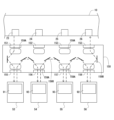
- FIG. 4 is a diagram for explaining the structure (initial state) of the optical direct path switch.
- FIG. 5 is a diagram showing an example of the configuration of the event database of FIG.
- FIG. 6 is a diagram showing the configuration of the switching circuit of FIG.
- FIG. 7 is a diagram showing the hardware configuration of a controller according to an embodiment of the present invention.
- FIG. 8 is a block diagram showing the internal configuration of a controller according to an embodiment of the present invention.
- FIG. 9 is a schematic diagram of the chain structure of the service chain of FIG.
- FIG. 10 is a diagram for explaining the structure of the optical direct path switch after being controlled by the controller.
- FIG. 11 is a diagram for explaining the structure of the optical direct path switch after being controlled
- a controller 100 is connected to a network switch (hereinafter simply referred to as a switch) 10.
- a network switch hereinafter simply referred to as a switch
- An ingress gateway server 52, function servers 53 to 56, and a database server 57 are connected to the switch 10.
- the switch 10 and the function servers 53 to 56 are connected so as to be capable of optical communication, with an optical direct path switch 150 being interposed between the two.
- the switch 10 the servers 51 to 57, the controller 100, and the optical direct path switch 150 constitute a data center FaaS (Function as a Service) system 1.
- the switch 10 is connected, via a network NW such as the Internet, to an administrator terminal T1 operated by a system administrator who manages the entire system 1.
- the network switch 10 is further connected, via the network NW, to a registrant terminal T2 operated by a service registrant who is a user of the system 1 and who creates and operates a service chain 90 (described below) in the system 1, and a customer terminal T3 operated by a customer who uses the service chain 90 (FIG. 2) (described below).
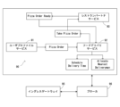
- service chain 90 as shown in FIG. 2 is constructed.
- service chain 90 is constructed as a pizza delivery system
- service chain 90 may be configured as any system.
- the service chain 90 includes three chained services: a user profile service 91, a food delivery service 92, and a restaurant partner service 93. Each service is defined by a function or code, etc.
- the service chain 90 is provided with an ingress gateway 95 and a broker 96.
- the ingress gateway 95 constitutes the entrance and exit point of the service chain 90.
- the ingress gateway 95 has known functions. For example, the ingress gateway 95 checks the source address (e.g., IP address) stored in the header of a packet sent to the system 1. If the source address is not a registered address, the ingress gateway 95 discards the packet, and if the source address is a registered address, the ingress gateway 95 supplies the packet to the broker 96.
- the operation of the broker 96 will be described later.
- the user profile service 91 performs a specified process when an order is input from the customer terminal T3 ( Figure 1) via the ingress gateway 95 and broker 96.
- the user profile service 91 completes the process, it notifies the food delivery service 92 of the occurrence of an event "Pizza Order” indicating that the process has been completed, together with the processing result.
- the food delivery service 92 performs a specified process, and when the process is completed, it notifies the restaurant partner service 93 of the occurrence of an event "Take Pizza Order” indicating that the process has been completed, together with the processing result.
- Restaurant partner service 93 receives the notification and starts the process to cook the pizza.
- restaurant partner service 93 notifies food delivery service 92 of the occurrence of event "Pizza Order Ready” indicating that the process has been completed, along with the processing result.
- Food delivery service 92 receives the notification and generates events "Schedule Delivery Time” and "Allocate Nearest Deliveryman” which lead to the process for delivering the pizza, and returns the order result to customer terminal T3.
- the operation of service chain 90 consists of a succession of processing by the service and the occurrence of an event indicating the end of processing.
- the occurrence of an event and the processing result are indicated by one packet or a set of multiple packets.
- This packet or set of packets is sent to the destination service, thereby notifying the occurrence of the event (i.e., the end of processing) and the processing result.
- the packet used for this notification is also called a notification packet.
- the broker 96 manages the destination of this notification packet.
- the broker 96 also performs load balancing for the destination of the packets.
- the various packets used in this embodiment, including the notification packet, are sent and received using TCP/IP.
- controller 100 and the servers 52 to 57 are each configured as server computers having different housings.
- the controller 100 is configured to monitor and manage each of the servers 52 to 55, manage events, deploy services such as the user profile service 91, and control the optical direct path switch 150.
- the ingress gateway server 52 is configured to operate as an ingress gateway 95.
- Services 91 to 93 that make up the service chain 90 are distributed and deployed to function servers 53 to 56. Here, it is assumed that services 91 to 93 are deployed to servers 53 to 55, respectively.
- the database server 57 holds various databases.
- the databases are referenced by the controller 100 and other servers 52 to 57 (including the service 91, etc.).
- the switch 10 is a programmable switch. Packets transmitted and received between the system 1 and the terminals T1 to T3, and packets transmitted and received between the controller 100 and the servers 52 to 57 pass through the switch 10. These packets include the notification packets transmitted and received between the services 91 to 93.
- the switch 10 and the function servers 53 to 56 are optically connected via an optical direct path switch 150.
- the optical direct path switch 150 is configured to be able to change the connection relationship between the switch 10 and each of the function servers 53 to 56 under the control of the controller 100.
- the service chain 90 in FIG. 2 is constructed in the system 1 by a service registrant.
- the service registrant operates the registrant terminal T2, logs in to the control server 51 via the switch 10, and constructs the service chain 90 via the control server 51.
- This construction includes deploying the services 91-93 to the function servers 53-55, and constructing databases and tables held by the database server 57 that are referenced when the services 91-93 perform processing.
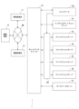
- the switch 10 includes multiple ports 21 to 28, a switching circuit 30, and a memory unit 40.
- Ports 21-27 are connected to the controller 100 and servers 52-57, respectively, and port 28 is connected to the network NW via a router (not shown) or the like.
- Ports 23-26 and function servers 53-56 are connected via an optical direct path switch 150 ( Figure 1).
- Ports 23-26 include optical signal/electrical signal converters (as do the ports of servers 53-56).
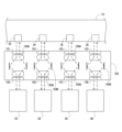
- ports 23 to 26 of the switch 10 are wired to ports 151 to 154 of the optical direct path switch 150.
- Ports 155 to 158 of the optical direct path switch 150 are wired to function servers 53 to 56, respectively.
- the optical direct path switch 150 is provided near each of the ports 151 to 158, and also includes eight circulators 159A that change the optical path for transmission and reception, and multiple movable mirrors 159B that reflect the optical signal whose optical path has been changed by the circulator 159A.
- optical paths are provided that connect the ports 151 to 154 and the ports 155 to 158, respectively. Therefore, for example, packets are sent and received between the port 23 and the function server 53.
- the orientation of each of the multiple mirrors 159B is controlled by the controller 100. This orientation control determines which of the ports 151 to 158 are optically connected to which other port, that is, the optical direct path switch 150 is controlled.
- the switching circuit 30 is configured to transmit a packet input to the switch 10 from one of the ports 21 to 28 to a port among the ports 21 to 28 that is associated with the destination of the packet.
- the switching circuit 30 also operates as a broker 96.
- the switching circuit 30 here is configured as either an ASIC (Application Specific Integrated Circuit) or an FPGA (Field-Programmable Gate Array), or as both.
- ASIC Application Specific Integrated Circuit
- FPGA Field-Programmable Gate Array
- the switching circuit 30 When the notification packet is input to the network switch 10, the switching circuit 30 outputs the notification packet (e.g., a notification packet related to the event "Pizza Order") to a port (e.g., port 23) associated with a server (e.g., server 53) on which the service that receives and processes the notification packet is deployed, with the service (e.g., service 92) as the destination.
- the switching circuit 30 operates as a broker 96 ( Figure 2).
- the notification packet handled by the switching circuit 30 has an event ID stored in the free space of the header or at the beginning of the payload.
- the beginning area of the payload in which the event ID is stored is also called the header.
- the payload also stores the processing results of the process that generates the event. For example, when service 91 sends a notification packet notifying the occurrence and processing results of the event "Pizza Order" indicating the end of processing by service 91, the notification packet includes the event ID of "Pizza Order" in the header and the processing results of service 91 (such as the order contents extracted from the order) in the payload, and sends the notification packet to service 92.
- the destination MAC address stored in the header of the notification packet may be, for example, the MAC address of the switch 10.
- the notification packet may include a service ID that identifies the service that sent it along with the event ID.
- a packet is not a notification packet, it does not include an event ID. Therefore, the presence or absence of an event ID determines whether a packet is a notification packet, that is, whether it is to be processed by the broker 96.
- Packets other than notification packets include packets supplied to the service chain 90.
- the header of the packet stores the IP address of one of the servers 53 to 57 on which the first service 91 of the service chain 90 is deployed as the destination address, and the packet includes designation information that designates the service 91, the data to be processed (such as a pizza order), and the like. As a result, the packet is processed by the service 91.
- These addresses and designation information may be set by the switching circuit 30, or may be set on the customer terminal T3 side.
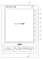
- the switching circuit 30 refers to the event database, server address table, and MAC address table. In FIG. 3, these are stored in the storage unit 40 of the switch 10, but they may also be stored in and referred to by the database server 57.
- the event database is a correspondence table that associates event IDs, sender service IDs, sender service addresses, receiver service IDs, and receiver service addresses.
- the names of events and services are used as the event IDs and service IDs, but each ID may be a number, etc.
- the event ID is information that identifies the event, and the same event ID is used as the one included in the notification packet.
- the sender's service ID and service address are the ID and address (such as a virtual address) that identify the service that sent the notification packet containing the corresponding event ID.
- the receiver's service ID and service address are the ID and address (such as a virtual address) that identify the service to which the notification packet containing the corresponding event ID is sent.
- the server address table is a correspondence table that associates a service address with the MAC address of one of the servers 53 to 56 on which the service of that service address is deployed.
- the MAC address table is a correspondence table that associates each port ID of ports 21 to 28 with the MAC address of the device, such as a server or router, connected to that port.
- the event database, server address table, and MAC address table may be constructed in any manner.
- the MAC address table may be automatically updated by the switch 10 using a known method.
- the event database and server address table are constructed, for example, by the service registrant via the registrant terminal T2.
- the switching circuit 30 includes a packet analysis unit 31, an attachment unit 32, a queue 33, and a transmission unit 34.
- Packets input to the switch 10 are input to the packet analysis unit 31.
- the packet analysis unit 31 analyzes the input packet and determines whether the packet includes an event ID. For example, the packet analysis unit 31 determines whether the packet includes any of the event IDs registered in an event database. If the packet header does not include an event ID, the packet analysis unit 31 sends the packet to the queue 33. In this case, the packet is not a notification packet transmitted and received in the service chain. If the packet includes an event ID, the packet analysis unit 31 sends the packet to the attachment unit 32. In this case, the packet is a notification packet transmitted and received in the service chain 90.
- the attachment unit 32 references the event database using the event ID contained in the packet as a key, and obtains the service ID and service address of the sender that correspond to the event ID.
- the assignment unit 32 refers to the server address table using the acquired service address as a key, and acquires the MAC address corresponding to the service address. This identifies the MAC address of one of the servers 53 to 56 on which the service of the service address is deployed.
- the attachment unit 32 rewrites the destination address in the header of the notification packet currently being processed to the MAC address obtained above, and stores the pair of the sender's service ID and service address in any free area of the notification packet. In this way, the attachment unit 32 adds information necessary for forwarding the notification packet to the next service to the notification packet. The attachment unit 32 then sends the notification packet to the queue 33.
- the queue 33 is composed of a predetermined buffer circuit, etc., and stores packets sent sequentially from the packet analysis unit 31 or the attachment unit 32.
- the transmitter 34 sequentially retrieves packets from the queue 33, and retrieves the port ID corresponding to the destination MAC address included in the header of the retrieved packet, using the destination MAC address included in the header as a key.
- the transmitter 34 transmits the currently retrieved packet to the port identified by the retrieved port ID.
- the packet is transmitted to the device having the destination MAC address, either the controller 100 or the servers 52 to 57.
- the destination server 53 to 56 of the notification packet causes the service having the service address included in the notification packet to perform processing.
- the processing uses the result of the previous service processing included in the payload of the notification packet.
- the service When the processing is completed, the service generates a new notification packet and returns it to the switch 10.
- the service ID and service address only the service address may be used.
- the functionality of the broker 96 is added to the switching circuit 30 on the ASIC and/or FPGA, which eliminates the need for multi-threaded processing using CPU resources for broker 96 processing. This reduces overhead such as context switching caused by multi-threading, and prevents deterioration of processing efficiency. Furthermore, reduced latency, reduced tail latency, and increased throughput are expected. Furthermore, the use of an ASIC or FPGA improves power efficiency compared to implementing a broker with a conventional CPU. Furthermore, the number of modules required is reduced, which reduces operational and procurement costs.
- the controller 100 comprises a processor 110, a main memory device 120, an auxiliary memory device 130, and an interface 140.
- the processor 110 comprises a CPU (Central Processing Unit) and the like.
- the main memory device 120 comprises a RAM (Random Access Memory) and functions as the main memory of the processor 110.
- the auxiliary memory device 130 comprises an SSD (Solid State Drive) and the like and stores various data in addition to programs.
- the interface 140 is connected by wire to port 21 of the switch 10 in FIG. 3.
- the processor 110 executes the programs in the auxiliary storage device 130 to operate as the detection unit 111, the optical path control unit 112, and the deployment unit 113 shown in FIG. 8.
- the detection unit 111 detects the chain structure of the chained services 91-93 and which of the function servers 53-56 each of the services 91-93 is deployed to. For example, the detection unit 111 monitors the event database and server address table at a predetermined interval, and identifies the chain structure of the services 91-93, that is, the service chain 90, and the servers to which each service is deployed (in this case, MAC addresses).
- the chain structure is identified, for example, by linking together records in which the receiving service address and the sending service address are the same. In the case of the event database in FIG. 5, the chain structure and the deployment destinations of each service are as shown in FIG. 9.
- the optical path control unit 112 rotates the mirror 159B so as to optically connect the function servers 53 and 54, on which the user profile service 91 and the next food delivery service 92, among the services 91 to 93, are deployed. This controls the optical path within the optical direct path switch 150. Similarly, the optical path control unit 112 controls the optical path within the optical direct path switch 150 so as to optically connect the function servers 54 and 55, on which the food delivery service 92 and the restaurant partner service 93 are deployed, to each other. The state controlled up to this point is shown in Figure 10.
- the food delivery service 92 again performs processing, but as shown in FIG. 10, the function servers 55 and 54 on which the services 93 and 92 are deployed, respectively, cannot be optically connected.
- the deployment unit 113 deploys the food delivery service 92 to the function server 55 and the function server 56 that can be optically connected via the optical direct path switch 150. Then, the optical path control unit 112 controls the optical path in the optical direct path switch 150 so as to optically connect the function server 55 and the function server 56. The state of control is shown in FIG. 11.
- the above-mentioned units 111 to 113 enable direct optical connections between the services 91, 92, 93, and 94 that make up the service chain 90, using the optical direct path switch 150, without going through the switch 10 or other servers.
- the switch 10 cannot operate as a broker 96.
- the optical path control unit 112 may set the target server among the function servers 53 to 56 to perform processing based on the notification packet when the target server receives a notification packet containing a specific event ID from the function server in which the service immediately before the service deployed on that server is deployed.
- the switch 10 and the function servers 53 to 56 cannot communicate with each other for other services, so it is preferable that a communication path other than the communication path via the optical direct path switch 150 is secured between them.
- the method of determining the mode of optical connection by the optical path control unit 112 may be performed by any algorithm prepared in advance taking into consideration the structure of the optical direct path switch 150, etc.
- the optical path control unit 112 and the deployment unit 113 may repeatedly control the optical direct path switch 150 with different contents and deploy services, and each time they are performed, check whether there are any problems with signal transmission.
- the optical path control unit 112 may control the optical direct path switch 150 by adopting an optical connection that does not cause any problems with signal transmission.
- the optical direct path switch 150 is controlled to optically connect the first server and the second server of the servers 53-56 on which the first service and the next second service of the services 91-93 are deployed, respectively.
- a broker is not interposed between the first service and the second service of the services 91-93, the occurrence of overhead of context switching by a conventional broker can be suppressed at least for this portion, and deterioration of the optical processing efficiency can be suppressed.
- reduction in latency, reduction in tail latency, and increase in throughput can be expected.
- the optical direct path switch provides lower latency than when the switch 10 is operated as a broker, and congestion is also avoided.
- the second service is deployed to a third server among the function servers 53 to 56 that can be optically connected to the first server by the optical direct path switch 150, and the optical path in the optical direct path switch is controlled to optically connect the first server to the third server.
- This increases the frequency with which optical connections can be made, suppresses the occurrence of context switch overhead, and suppresses deterioration of processing efficiency.
- the deployment unit 113 can realize optical connection even if the multiple services chained as described above include, for example, the same service. Even if the same service is not included, optical connection by the optical direct path switch 150 may be difficult depending on the deployment location of the service (specifically, which server it is deployed to). For example, among the services 91 to 93 in FIG. 10, service 91 is deployed to server 53, service 92 is deployed to server 55, service 93 is deployed to server 56, and no service is deployed to server 54. In such a case, the deployment locations of services 92 and 93 may be changed.
- the deployment unit 113 may delete the current services 92 and 93, newly deploy services 92 and 93 to servers 54 and 55, respectively, and newly deploy service 92 to server 56, thereby changing to the state of FIG. 11.
- the deployment unit 113 may deploy the second service to a third server that can be optically connected to the first server by the optical direct path switch, and erase the second service deployed to the second server. This also allows the optical connection to be realized by the subsequent control of the optical path control unit 112.
- the optical path control unit 112 may optically connect the first server and the second server to the network switch (including a switch that operates as a broker) 10. This ensures that the first server and the second server have a communication partner.
- the optical direct path switch 150 only needs to have an optical path that optically connects a first server computer and a second server computer among a plurality of server computers on which a first service and a second service among a plurality of chained services are respectively deployed, and other configurations are optional.
- the optical direct path switch 150 may also be configured to be interposed between the switch 10 and the ingress gateway server 52, etc.
- the number of function servers, the number of service chains to be deployed, the number of services that make up the service chains, etc. are arbitrary.
- the functions of servers 51 to 55 may be assigned to one server computer, or may be distributed across two or more server computers.
- each of the units 111 to 113 of the controller 100 is arbitrary, and at least a portion of each of the units 111 to 113 may be configured with an ASIC and/or an FPGA.
- a portion or the entirety of the detection unit 111 may be configured with an ASIC.
- a plurality of switches 10 may be provided.
- a switch 10, controller 100, servers 52 and 57 may be provided for some of the function servers 53 to 56, and other switches 10, controllers 100, servers 52 and 57 may be provided for the remaining function servers.
- the present invention is not limited to the above-described embodiments and modifications.
- the present invention includes various modifications to the above-described embodiments and modifications that can be understood by a person skilled in the art within the scope of the technical concept of the present invention.
- the configurations listed in the above-described embodiments and modifications can be combined as appropriate to the extent that there is no contradiction. It is also possible to delete any of the above-described configurations.
- a controller configured to control an optical direct path switch to which a plurality of server computers are connected, A detection unit configured to detect a chain structure of a plurality of chained services and to which of the plurality of server computers each of the plurality of services is deployed; an optical path control unit configured to control the optical direct path switch so as to optically connect a first server computer and a second server computer among the plurality of server computers on which a first service and a second service next to the first service are deployed, respectively, based on a detection result of the detection unit;
- a controller comprising: (Appendix 2) a deployer configured to deploy the second service to a third server computer among the plurality of server computers, the third server computer being optically connectable to the first server computer via the optical direct path switch when the first server computer and the second server computer cannot be optically connected to each other via the optical direct path switch; the optical path control unit is configured to control the
- the controller of claim 1 The deployment unit is configured to delete the second service deployed on the second computer. 3.
- the controller of claim 2. The deployer is configured to deploy the second service to the third server computer in addition to the second service deployed to the second server computer. 4.
- the controller of claim 2 or 3. the optical path control unit optically connects the first server computer and the second server computer to a network switch when the first server computer and the second server computer cannot be optically connected by the optical direct path switch; 5.
- the controller according to any one of claims 1 to 4.
- Appendix 6 A program that causes a computer to function as the controller described in appendix 1.
Landscapes
- Engineering & Computer Science (AREA)
- Physics & Mathematics (AREA)
- Computer Hardware Design (AREA)
- Theoretical Computer Science (AREA)
- Computer Networks & Wireless Communication (AREA)
- Signal Processing (AREA)
- Mathematical Physics (AREA)
- Software Systems (AREA)
- General Engineering & Computer Science (AREA)
- General Physics & Mathematics (AREA)
- Data Exchanges In Wide-Area Networks (AREA)
Priority Applications (2)
| Application Number | Priority Date | Filing Date | Title |
|---|---|---|---|
| PCT/JP2023/012869 WO2024201803A1 (ja) | 2023-03-29 | 2023-03-29 | コントローラ、プログラム、及び、光ダイレクトパススイッチ |
| JP2025509417A JPWO2024201803A1 (https=) | 2023-03-29 | 2023-03-29 |
Applications Claiming Priority (1)
| Application Number | Priority Date | Filing Date | Title |
|---|---|---|---|
| PCT/JP2023/012869 WO2024201803A1 (ja) | 2023-03-29 | 2023-03-29 | コントローラ、プログラム、及び、光ダイレクトパススイッチ |
Publications (1)
| Publication Number | Publication Date |
|---|---|
| WO2024201803A1 true WO2024201803A1 (ja) | 2024-10-03 |
Family
ID=92903620
Family Applications (1)
| Application Number | Title | Priority Date | Filing Date |
|---|---|---|---|
| PCT/JP2023/012869 Ceased WO2024201803A1 (ja) | 2023-03-29 | 2023-03-29 | コントローラ、プログラム、及び、光ダイレクトパススイッチ |
Country Status (2)
| Country | Link |
|---|---|
| JP (1) | JPWO2024201803A1 (https=) |
| WO (1) | WO2024201803A1 (https=) |
Citations (2)
| Publication number | Priority date | Publication date | Assignee | Title |
|---|---|---|---|---|
| JP2016533689A (ja) * | 2013-09-13 | 2016-10-27 | テレフオンアクチーボラゲット エルエム エリクソン(パブル) | 複数インスタンスを伴うインラインサービス変更のためのサービス配置 |
| US20170251285A1 (en) * | 2014-10-31 | 2017-08-31 | Hewlett Packard Enterprise Development Lp | Optical circuit switch |
-
2023
- 2023-03-29 JP JP2025509417A patent/JPWO2024201803A1/ja active Pending
- 2023-03-29 WO PCT/JP2023/012869 patent/WO2024201803A1/ja not_active Ceased
Patent Citations (2)
| Publication number | Priority date | Publication date | Assignee | Title |
|---|---|---|---|---|
| JP2016533689A (ja) * | 2013-09-13 | 2016-10-27 | テレフオンアクチーボラゲット エルエム エリクソン(パブル) | 複数インスタンスを伴うインラインサービス変更のためのサービス配置 |
| US20170251285A1 (en) * | 2014-10-31 | 2017-08-31 | Hewlett Packard Enterprise Development Lp | Optical circuit switch |
Also Published As
| Publication number | Publication date |
|---|---|
| JPWO2024201803A1 (https=) | 2024-10-03 |
Similar Documents
| Publication | Publication Date | Title |
|---|---|---|
| US7913106B2 (en) | Failover in a host concurrently supporting multiple virtual IP addresses across multiple adapters | |
| EP3058704B1 (en) | System and method for software defined network aware data replication | |
| US6665304B2 (en) | Method and apparatus for providing an integrated cluster alias address | |
| EP3629554B1 (en) | Method, apparatus, and system for load balancing of service chain | |
| US7315896B2 (en) | Server network controller including packet forwarding and method therefor | |
| JP5381998B2 (ja) | クラスタ制御システム、クラスタ制御方法、及びプログラム | |
| JP2006202280A (ja) | 状態の同期化を有するクラスタのための仮想マルチキャスト経路指定 | |
| JP2011160041A (ja) | フロントエンドシステム、フロントエンド処理方法 | |
| US6389550B1 (en) | High availability protocol computing and method | |
| EP4311248B1 (en) | Real-time detection of completion of sensor wrap completion in gnmi telemetry of a network device | |
| CN106357542B (zh) | 提供组播业务的方法和软件定义网络控制器 | |
| CN112788060A (zh) | 数据包传输方法和装置、存储介质和电子设备 | |
| KR101870146B1 (ko) | 리프-스파인 구조의 소프트웨어 정의 네트워킹에서 목적지 기반 패킷 전송 제어 방법 및 장치 | |
| US8004973B2 (en) | Virtual inline configuration for a network device | |
| US9634894B2 (en) | Network service aware routers, and applications thereof | |
| US20190068688A1 (en) | Secure remote computer network | |
| CN116546040B (zh) | 用于针对一个或多个分布式宽带网络网关(bng)用户平面设备提供bng控制平面的集成bng设备 | |
| US20030229713A1 (en) | Server network controller including server-directed packet forwarding and method therefor | |
| CN110932992A (zh) | 一种基于隧道模式的负载均衡通信方法 | |
| WO2022031162A1 (en) | A system and method for mqtt client based high availability | |
| CN109474713A (zh) | 报文转发方法和装置 | |
| KR102116245B1 (ko) | 분산 클라우드 환경에서 오픈플로우 스위치 기반 전송 경로 설정을 위한 방법 및 장치 | |
| WO2024201803A1 (ja) | コントローラ、プログラム、及び、光ダイレクトパススイッチ | |
| CN116962287A (zh) | 业务流量调度的方法、装置、电子设备及存储介质 | |
| JP4574684B2 (ja) | 通信ネットワークシステム及びこれを用いたメッセージルーティング方法 |
Legal Events
| Date | Code | Title | Description |
|---|---|---|---|
| 121 | Ep: the epo has been informed by wipo that ep was designated in this application |
Ref document number: 23930441 Country of ref document: EP Kind code of ref document: A1 |
|
| ENP | Entry into the national phase |
Ref document number: 2025509417 Country of ref document: JP Kind code of ref document: A |
|
| WWE | Wipo information: entry into national phase |
Ref document number: 2025509417 Country of ref document: JP |
|
| NENP | Non-entry into the national phase |
Ref country code: DE |
|
| 122 | Ep: pct application non-entry in european phase |
Ref document number: 23930441 Country of ref document: EP Kind code of ref document: A1 |