WO2024201777A1 - エアロゾル生成システム - Google Patents
エアロゾル生成システム Download PDFInfo
- Publication number
- WO2024201777A1 WO2024201777A1 PCT/JP2023/012805 JP2023012805W WO2024201777A1 WO 2024201777 A1 WO2024201777 A1 WO 2024201777A1 JP 2023012805 W JP2023012805 W JP 2023012805W WO 2024201777 A1 WO2024201777 A1 WO 2024201777A1
- Authority
- WO
- WIPO (PCT)
- Prior art keywords
- battery
- temperature
- aerosol
- opening
- battery pack
- Prior art date
- Legal status (The legal status is an assumption and is not a legal conclusion. Google has not performed a legal analysis and makes no representation as to the accuracy of the status listed.)
- Ceased
Links
Images



Classifications
-
- A—HUMAN NECESSITIES
- A24—TOBACCO; CIGARS; CIGARETTES; SIMULATED SMOKING DEVICES; SMOKERS' REQUISITES
- A24F—SMOKERS' REQUISITES; MATCH BOXES; SIMULATED SMOKING DEVICES
- A24F40/00—Electrically operated smoking devices; Component parts thereof; Manufacture thereof; Maintenance or testing thereof; Charging means specially adapted therefor
- A24F40/50—Control or monitoring
- A24F40/51—Arrangement of sensors
-
- A—HUMAN NECESSITIES
- A24—TOBACCO; CIGARS; CIGARETTES; SIMULATED SMOKING DEVICES; SMOKERS' REQUISITES
- A24F—SMOKERS' REQUISITES; MATCH BOXES; SIMULATED SMOKING DEVICES
- A24F40/00—Electrically operated smoking devices; Component parts thereof; Manufacture thereof; Maintenance or testing thereof; Charging means specially adapted therefor
- A24F40/10—Devices using liquid inhalable precursors
-
- A—HUMAN NECESSITIES
- A24—TOBACCO; CIGARS; CIGARETTES; SIMULATED SMOKING DEVICES; SMOKERS' REQUISITES
- A24F—SMOKERS' REQUISITES; MATCH BOXES; SIMULATED SMOKING DEVICES
- A24F40/00—Electrically operated smoking devices; Component parts thereof; Manufacture thereof; Maintenance or testing thereof; Charging means specially adapted therefor
- A24F40/20—Devices using solid inhalable precursors
-
- A—HUMAN NECESSITIES
- A24—TOBACCO; CIGARS; CIGARETTES; SIMULATED SMOKING DEVICES; SMOKERS' REQUISITES
- A24F—SMOKERS' REQUISITES; MATCH BOXES; SIMULATED SMOKING DEVICES
- A24F40/00—Electrically operated smoking devices; Component parts thereof; Manufacture thereof; Maintenance or testing thereof; Charging means specially adapted therefor
- A24F40/40—Constructional details, e.g. connection of cartridges and battery parts
-
- A—HUMAN NECESSITIES
- A24—TOBACCO; CIGARS; CIGARETTES; SIMULATED SMOKING DEVICES; SMOKERS' REQUISITES
- A24F—SMOKERS' REQUISITES; MATCH BOXES; SIMULATED SMOKING DEVICES
- A24F40/00—Electrically operated smoking devices; Component parts thereof; Manufacture thereof; Maintenance or testing thereof; Charging means specially adapted therefor
- A24F40/50—Control or monitoring
-
- A—HUMAN NECESSITIES
- A24—TOBACCO; CIGARS; CIGARETTES; SIMULATED SMOKING DEVICES; SMOKERS' REQUISITES
- A24F—SMOKERS' REQUISITES; MATCH BOXES; SIMULATED SMOKING DEVICES
- A24F40/00—Electrically operated smoking devices; Component parts thereof; Manufacture thereof; Maintenance or testing thereof; Charging means specially adapted therefor
- A24F40/50—Control or monitoring
- A24F40/53—Monitoring, e.g. fault detection
-
- H—ELECTRICITY
- H02—GENERATION; CONVERSION OR DISTRIBUTION OF ELECTRIC POWER
- H02J—ELECTRIC POWER NETWORKS; CIRCUIT ARRANGEMENTS OR SYSTEMS FOR SUPPLYING OR DISTRIBUTING ELECTRIC POWER; SYSTEMS FOR STORING ELECTRIC ENERGY
- H02J7/00—Circuit arrangements for charging or discharging batteries or for supplying loads from batteries
- H02J7/60—Circuit arrangements for charging or discharging batteries or for supplying loads from batteries including safety or protection arrangements
-
- H—ELECTRICITY
- H02—GENERATION; CONVERSION OR DISTRIBUTION OF ELECTRIC POWER
- H02J—ELECTRIC POWER NETWORKS; CIRCUIT ARRANGEMENTS OR SYSTEMS FOR SUPPLYING OR DISTRIBUTING ELECTRIC POWER; SYSTEMS FOR STORING ELECTRIC ENERGY
- H02J7/00—Circuit arrangements for charging or discharging batteries or for supplying loads from batteries
- H02J7/70—Circuit arrangements for charging or discharging batteries or for supplying loads from batteries characterised by the mechanical construction
- H02J7/751—Circuit arrangements for charging or discharging batteries or for supplying loads from batteries characterised by the mechanical construction concerning the insertion or the connection of the batteries
-
- H—ELECTRICITY
- H02—GENERATION; CONVERSION OR DISTRIBUTION OF ELECTRIC POWER
- H02J—ELECTRIC POWER NETWORKS; CIRCUIT ARRANGEMENTS OR SYSTEMS FOR SUPPLYING OR DISTRIBUTING ELECTRIC POWER; SYSTEMS FOR STORING ELECTRIC ENERGY
- H02J7/00—Circuit arrangements for charging or discharging batteries or for supplying loads from batteries
- H02J7/90—Regulation of charging or discharging current or voltage
-
- Y—GENERAL TAGGING OF NEW TECHNOLOGICAL DEVELOPMENTS; GENERAL TAGGING OF CROSS-SECTIONAL TECHNOLOGIES SPANNING OVER SEVERAL SECTIONS OF THE IPC; TECHNICAL SUBJECTS COVERED BY FORMER USPC CROSS-REFERENCE ART COLLECTIONS [XRACs] AND DIGESTS
- Y02—TECHNOLOGIES OR APPLICATIONS FOR MITIGATION OR ADAPTATION AGAINST CLIMATE CHANGE
- Y02E—REDUCTION OF GREENHOUSE GAS [GHG] EMISSIONS, RELATED TO ENERGY GENERATION, TRANSMISSION OR DISTRIBUTION
- Y02E60/00—Enabling technologies; Technologies with a potential or indirect contribution to GHG emissions mitigation
- Y02E60/10—Energy storage using batteries
Definitions
- This disclosure relates to an aerosol generation system.
- an inhalation device that generates an aerosol imparted with a flavor component using a base material that includes an aerosol source for generating an aerosol and a flavor source for imparting a flavor component to the generated aerosol.
- a user can taste the flavor by inhaling the aerosol imparted with the flavor component generated by the inhalation device.
- the action of a user inhaling an aerosol is hereinafter also referred to as a puff or a puffing action.
- Patent Document 1 discloses a suction device in which the battery can be replaced by removing a cover provided on the side of the suction device.
- Patent Document 1 does not fully consider the temperature of the battery. The higher the temperature of the battery, the more likely it is that various problems, such as breakdowns, will occur.
- the present disclosure has been made in consideration of the above problems, and the purpose of the present disclosure is to provide a mechanism that enables a battery to be operated at a more appropriate temperature.
- an aerosol generation system comprising: a first storage section for storing a substrate containing an aerosol source; a load for generating energy for heating the aerosol source contained in the substrate stored in the first storage section; a second storage section for storing a battery for supplying power to the load; a temperature sensor disposed in the second storage section for measuring the temperature of the battery stored in the second storage section; and a control section for controlling the operation of the load based on the temperature detected by the temperature sensor, wherein the first storage section has a first opening and stores the substrate removably so that it can be inserted in a first direction through the first opening and removed in a second direction; the second storage section has a second opening and stores the battery removably so that it can be inserted in a third direction through the second opening and removed in a fourth direction; and the temperature sensor is disposed on an inner wall of the second storage section on the third direction side or the fourth direction side.
- the temperature sensor may be positioned adjacent to a portion of the surface of the battery that is expected to be hottest when the load is in operation.
- the temperature sensor may be positioned closer to the surface of the battery than to the center of the battery and closer to the load.
- the control unit may estimate a maximum temperature of the battery based on the temperature detected by the temperature sensor, and control the operation of the load based on the estimated maximum temperature of the battery.
- the aerosol generating system may include a plurality of temperature sensors, and the control unit may control the operation of the load based on the highest temperature among the temperatures detected by the plurality of temperature sensors.
- the second storage section may further include a lid portion that opens and closes the second opening, and the lid portion may be attached/detached or rotated to open and close the second opening.
- the aerosol generating system may further include an opening/closing sensor that detects the opening and closing of the second opening by the lid, and the control unit may control the operation of the load based on the detection result by the opening/closing sensor.
- the control unit may control charging of the battery based on the detection result of the open/close sensor.
- the aerosol generation system may include a terminal electrically connected to the battery, the control unit may be disposed on the second direction side of the second storage unit, and the terminal may be disposed on the inner wall of the second storage unit on the second direction side at a position offset from the load in the third direction or the fourth direction.
- the aerosol generation system may include a terminal electrically connected to the battery, and the terminal may be configured as an elastic body.
- the aerosol generating system may further include a first through hole that connects the internal space of the first container to the internal space of the second container, and a second through hole that connects the internal space of the second container to the outside.
- the aerosol generation system may further include a charging terminal that receives power for charging the battery supplied from an external power source, and the charging terminal may be disposed on the second direction side of the second storage section.
- the first and second directions may be perpendicular or substantially perpendicular to the third and fourth directions.
- the aerosol generating system may further include the battery.
- the aerosol generating system may further include the substrate.
- this disclosure provides a mechanism that allows the battery to be operated at a more appropriate temperature.
- FIG. 2 is a schematic diagram showing a configuration example of a suction device.
- 1 is a perspective view showing an example of an external configuration of a suction device according to an embodiment of the present invention
- 1 is a diagram illustrating an internal configuration of a suction device according to an embodiment of the present invention
- 1 is a diagram illustrating an internal configuration of a suction device according to an embodiment of the present invention
- FIG. 11 is a diagram for explaining a first modified example.
- FIG. 13 is a diagram for explaining a second modified example.
- FIG. 13 is a diagram for explaining a third modified example.
- FIG. 4 is a diagram for explaining an example of an air flow path in the suction device.
- 10 is a diagram for explaining another example of an air flow path in the suction device.
- FIG. 10 is a diagram for explaining another example of an air flow path in the suction device.
- FIG. 10 is a diagram for explaining another example of an air flow path in the suction device.
- FIG. 10 is a
- elements having substantially the same functional configuration may be distinguished by assigning an index containing different letters or numbers after the same reference numeral.
- multiple elements having substantially the same functional configuration may be distinguished as necessary, such as devices 1-1, 1-2, and 1-3.
- only the same reference numerals are used.
- devices 1-1, 1-2, and 1-3 they may also be simply referred to as device 1.
- the inhalation device is a device that generates a substance to be inhaled by a user.
- the substance generated by the inhalation device is described as an aerosol.
- the substance generated by the inhalation device may be a gas.
- FIG. 1 is a schematic diagram showing an example of the configuration of a suction device.
- the suction device 100 includes a power supply unit 111, a sensor unit 112, a notification unit 113, a memory unit 114, a communication unit 115, a control unit 116, a heating unit 121, a storage unit 140, and a heat insulating unit 144.
- the power supply unit 111 stores power.
- the power supply unit 111 supplies power to each component of the suction device 100 under the control of the control unit 116.
- the power supply unit 111 may be configured, for example, by a rechargeable battery such as a lithium ion secondary battery.
- the sensor unit 112 acquires various information related to the suction device 100.
- the sensor unit 112 is configured with a pressure sensor such as a condenser microphone, a flow rate sensor, or a temperature sensor, and acquires values associated with suction by the user.
- the sensor unit 112 is configured with an input device such as a button or switch that accepts information input from the user.
- the notification unit 113 notifies the user of information.
- the notification unit 113 is composed of, for example, a light-emitting device that emits light, a display device that displays an image, a sound output device that outputs sound, or a vibration device that vibrates.
- the storage unit 114 stores various information for the operation of the suction device 100.
- the storage unit 114 is configured, for example, from a non-volatile storage medium such as a flash memory.
- the communication unit 115 is a communication interface capable of performing communication conforming to any wired or wireless communication standard.
- Such communication standards may include, for example, standards using Wi-Fi (registered trademark), Bluetooth (registered trademark), BLE (Bluetooth Low Energy (registered trademark)), NFC (Near Field Communication), or LPWA (Low Power Wide Area).
- the control unit 116 functions as an arithmetic processing unit and a control unit, and controls the overall operation of the suction device 100 in accordance with various programs.
- the control unit 116 is realized by an electronic circuit such as a CPU (Central Processing Unit) or a microprocessor.
- the storage section 140 has an internal space 141 and holds the stick-shaped substrate 150 while storing a part of the stick-shaped substrate 150 in the internal space 141.
- the storage section 140 has an opening 142 that connects the internal space 141 to the outside, and stores the stick-shaped substrate 150 inserted into the internal space 141 through the opening 142.
- the storage section 140 is a cylindrical body with the opening 142 and the bottom 143 as the bottom surface, and defines a columnar internal space 141.
- An air flow path that supplies air to the internal space 141 is connected to the storage section 140.
- An air inlet hole which is an air inlet to the air flow path, is arranged, for example, on the side of the suction device 100.
- An air outlet hole which is an air outlet from the air flow path to the internal space 141, is arranged, for example, on the bottom 143.
- the stick-type substrate 150 includes a substrate portion 151 and a mouthpiece portion 152.
- the substrate portion 151 includes an aerosol source.
- the aerosol source includes a flavor component derived from tobacco or non-tobacco.
- the aerosol source may include a medicine.
- the aerosol source may be a liquid such as polyhydric alcohols such as glycerin and propylene glycol, and water, which include a flavor component derived from tobacco or non-tobacco, or may be a solid which includes a flavor component derived from tobacco or non-tobacco.
- the stick-type substrate 150 When the stick-type substrate 150 is held in the storage portion 140, at least a portion of the substrate portion 151 is stored in the internal space 141, and at least a portion of the mouthpiece portion 152 protrudes from the opening 142.
- the suction mouth portion 152 protruding from the opening 142 in their mouth and inhales air flows into the internal space 141 via an air flow path (not shown) and reaches the user's mouth together with the aerosol generated from the base portion 151.
- the heating unit 121 generates aerosol by heating the aerosol source and atomizing the aerosol source.
- the heating unit 121 is configured in a film shape and is arranged to cover the outer periphery of the storage unit 140.
- the heating unit 121 generates heat, the substrate unit 151 of the stick-shaped substrate 150 is heated from the outer periphery, and an aerosol is generated.
- the heating unit 121 generates heat when power is supplied from the power supply unit 111.
- power may be supplied when the sensor unit 112 detects that the user has started inhaling and/or that specific information has been input. Power supply may be stopped when the sensor unit 112 detects that the user has stopped inhaling and/or that specific information has been input.
- the insulating section 144 prevents heat transfer from the heating section 121 to other components.
- the insulating section 144 is made of a vacuum insulating material or an aerogel insulating material.
- the configuration of the suction device 100 is not limited to the above, and various configurations such as those exemplified below are possible.
- the heating unit 121 may be configured in a blade shape and disposed so as to protrude from the bottom 143 of the storage unit 140 into the internal space 141.
- the blade-shaped heating unit 121 is inserted into the substrate 151 of the stick-shaped substrate 150 and heats the substrate 151 of the stick-shaped substrate 150 from the inside.
- the heating unit 121 may be disposed so as to cover the bottom 143 of the storage unit 140.
- the heating unit 121 may be configured as a combination of two or more of a first heating unit that covers the outer periphery of the storage unit 140, a blade-shaped second heating unit, and a third heating unit that covers the bottom 143 of the storage unit 140.
- the storage unit 140 may include an opening/closing mechanism such as a hinge that opens and closes a portion of the outer shell that forms the internal space 141. The storage unit 140 may then open and close the outer shell to accommodate the stick-shaped substrate 150 inserted into the internal space 141 while clamping it.
- the heating unit 121 may be provided at the clamping location in the storage unit 140, and may heat the stick-shaped substrate 150 while pressing it.
- the means for atomizing the aerosol source is not limited to heating by the heating unit 121.
- the means for atomizing the aerosol source may be induction heating.
- the suction device 100 has at least an electromagnetic induction source such as a coil that generates a magnetic field, instead of the heating unit 121.
- a susceptor that generates heat by induction heating may be provided in the suction device 100, or may be included in the stick-shaped substrate 150.
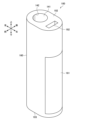
- FIG. 2 is a perspective view showing an example of the external configuration of the suction device 100 according to this embodiment.
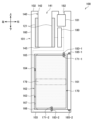
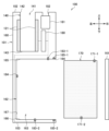
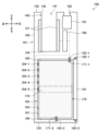
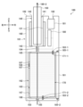
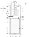
- Figures 3 and 4 are diagrams that generally show the internal configuration of the suction device 100 according to this embodiment.
- the suction device 100 may be configured as an oval-shaped straight cylinder with a top surface 102 and a bottom surface 103.
- the suction device 100 is configured to a size that can be held by a user, and is used while being held by the user.
- the surface of the suction device 100 may be provided with a user interface, such as buttons for inputting operating instructions to the suction device 100, or a display that displays the operating status of the suction device 100.
- the direction in which the stick-shaped substrate 150 is inserted into and removed from the storage section 140 is also referred to as the up-down direction.
- the up-down direction corresponds to the longitudinal direction of the suction device 100.
- the longitudinal direction of the cross section of the suction device 100 is also referred to as the left-right direction, and the short-side direction is also referred to as the front-rear direction.
- the suction device 100 has a housing 160, a cover portion 161, a battery chamber 162, a control circuit 180, a charging circuit 181, a charging terminal 182, battery terminals 183 (183-1 and 183-2), a temperature sensor 184, and an opening/closing sensor 185 (185-1 and 185-2).
- a battery pack 170 is detachably attached to the suction device 100.
- the control circuit 180 and the charging circuit 181 correspond to the control unit 116 shown in Figure 1.
- the battery pack 170 corresponds to the power supply unit 111 shown in Figure 1.
- the temperature sensor 184 and the opening/closing sensor 185 correspond to the sensor unit 112 shown in Figure 1.
- the housing 160 constitutes the outermost shell of the suction device 100. As shown in Figures 2 to 4, an opening 142 is provided on the top surface 102 of the housing 160. The stick-shaped substrate 150 is inserted into and removed from the storage section 140 through the opening 142.
- the storage section 140 is an example of a first storage section that stores the stick-shaped substrate 150.
- the storage section 140 removably stores the stick-shaped substrate 150 so that it can be inserted downward through the opening 142 (an example of a first opening) and removed upward.
- the downward direction is an example of a first direction, which is the insertion direction of the stick-shaped substrate 150.
- the upward direction is an example of a second direction, which is the removal direction of the stick-shaped substrate 150.
- the battery chamber 162 is an example of a second storage section that stores the battery pack 170.
- the battery chamber 162 has an internal space 163, and stores the battery pack 170 in the internal space 163.
- the battery chamber 162 has an opening 164 (an example of a second opening) that connects the internal space 163 to the outside.
- the battery pack 170 is inserted into and removed from the battery chamber 162 through the opening 164.
- the battery chamber 162 accommodates the battery pack 170 so that it can be inserted to the left through the opening 164 and removed to the right.
- the left direction is an example of a third direction, which is the insertion direction of the battery pack 170.
- the right direction is an example of a fourth direction, which is the removal direction of the battery pack 170.
- the battery chamber 162 has a lid 161 that opens and closes the opening 164.
- the lid 161 may be attached and detached to open and close the opening 164.
- FIG. 3 illustrates a state in which the lid 161 closes the opening 164 and a battery pack 170 is housed in the battery chamber 162.
- FIG. 4 illustrates a state in which the lid 161 opens the opening 164 and the battery pack 170 has been removed from the battery chamber 162.
- the battery chamber 162 may be configured in a shape that circumscribes the battery pack 170.
- the battery pack 170 be configured in a shape that is difficult to rotate around the vertical axis when housed in the battery chamber 162, such as an elliptical cylinder or a rectangular cylinder. With such a configuration, it is possible to limit the rotation of the battery pack 170 within the battery chamber 162, and easily maintain the connection between the battery terminal 183 and the electrode 171, which will be described later.
- the battery pack 170 is configured in a rectangular cylinder shape.
- the battery chamber 162 defines a rectangular parallelepiped internal space 163.
- the battery pack 170 is a rechargeable battery that is configured to be detachable from the suction device 100.
- the portion of the suction device 100 excluding the battery pack 170 is also referred to as the main body 101.
- the battery pack 170 supplies power to the components housed in the main body 101, including the heating unit 121.
- the battery pack 170 has multiple electrodes 171 (171-1 and 171-2).
- the electrode 171-1 may be a positive electrode
- the electrode 171-2 may be a negative electrode.
- the battery pack 170 may increase in temperature during charging and discharging, or due to heat transfer from the heating unit 121.
- the main body 101 of the suction device 100 has multiple battery terminals 183 (183-1 and 183-2).
- the battery terminals 183 are electrically connected to the battery pack 170. That is, the battery terminals 183 are a power interface between the battery pack 170 and the components within the main body 101 of the suction device 100.
- the battery terminals 183 are connected to the heating unit 121 and the charging circuit 181 via conductors shown by dashed lines, and transmit and receive power between them. Electrical connections with other components are omitted from Figures 3 and 4.
- each of the multiple battery terminals 183 is detachably connected to each of the multiple electrodes 171 of the battery pack 170.
- the battery terminal 183-1 is connected to the electrode 171-1
- the battery terminal 183-2 is connected to the electrode 171-2.
- the battery terminal 183-1 is disposed on the upper inner wall 165 of the battery chamber 162 and is connected to the electrode 171-1 disposed on the upper side of the battery pack 170.
- the battery terminal 183-2 is disposed on the lower inner wall 166 of the battery chamber 162 and is connected to the electrode 171-2 disposed on the lower side of the battery pack 170.
- the battery terminal 183 may be made of an elastic body such as a wire spring or a leaf spring.
- the elastic body serving as the battery terminal 183 is pressed into the electrode 171 while in contact with it as the battery pack 170 is inserted into the battery chamber 162, exerting an elastic force in the direction of sandwiching the battery pack 170.
- the battery terminal 183 and the electrode 171 can be brought into stronger contact with each other when the battery pack 170 is housed in the battery chamber 162. As a result, it is possible to reduce the contact resistance at the connection point between the battery terminal 183 and the electrode 171.
- the battery terminal 183 is preferably made of a heat-resistant metal.
- heat-resistant metals include copper-based alloys such as phosphor bronze and Corson alloy. This is because copper has lower electrical resistance than aluminum and the like. With this configuration, it is possible to suppress relaxation of the elastic force of the battery terminal 183 that accompanies an increase in temperature of the battery terminal 183. As a result, even if the temperature of the battery terminal 183 increases due to heat transfer from the heating unit 121 or the battery pack 170, it is possible to suppress an increase in contact resistance at the connection point between the battery terminal 183 and the electrode 171.
- the battery terminals 183 are gold plated or the like to prevent rust and reduce contact resistance.
- the control circuit 180 and the charging circuit 181 are disposed above the battery chamber 162.
- the battery terminal 183-1 is disposed at a position offset from the heating unit 121 in the left-right direction (or front-back direction) on the upper inner wall 165 of the battery chamber 162.
- the offset position here refers to a position that is separated or does not overlap.
- the battery terminal 183-1 is disposed directly below the control circuit 180 or the charging circuit 181. With this configuration, it is possible to minimize the distance between the battery terminal 183-1 and the control circuit 180 and the charging circuit 181, thereby reducing the power loss in the conductor.
- the temperature sensor 184 is disposed in the battery chamber 162.
- the temperature sensor 184 measures the temperature of the battery pack 170 housed in the battery chamber 162. For example, as shown in FIG. 3, the temperature sensor 184 abuts against the battery pack 170 housed in the battery chamber 162 and measures the surface temperature of the battery pack 170. Alternatively, the temperature sensor 184 may abut indirectly against the battery pack 170 housed in the battery chamber 162 via a heat-conductive member, or may measure the surface temperature of the battery pack 170 via the heat-conductive member.
- the temperature sensor 184 may be, for example, a thermistor.
- the temperature sensor 184 is disposed on the left inner wall 167 of the battery chamber 162, which is the inner wall on the side in the direction in which the battery pack 170 is inserted. With this configuration, the temperature sensor 184 and the battery pack 170 come into contact only when the battery pack 170 is fully inserted. This prevents friction between the temperature sensor 184 and the battery pack 170 that occurs when the battery pack 170 is inserted and removed, making it possible to suppress misalignment and failure of the temperature sensor 184.
- the temperature sensor 184 is positioned so as to be close to (e.g., directly or indirectly in contact with) the portion of the surface of the battery pack 170 that is expected to be the hottest when the heating section 121 is in operation. This configuration makes it possible to improve the accuracy of various controls, described below, that are based on the temperature detected by the temperature sensor 184.
- the temperature sensor 184 is disposed close to the heating section 121 on the surface of the battery pack 170 rather than the center of the battery pack 170.
- the temperature sensor 184 is disposed so as to abut between the center of the battery pack 170 in the vertical direction and the upper end of the battery pack 170.
- the center becomes the hottest, so it is assumed that the part of the surface of the battery pack 170 closest to the center, i.e., the vertical central portion 179, becomes the hottest of the battery pack 170's surface.
- the temperature sensor 184 is able to detect the surface temperature of the part of the surface of the battery pack 170 that is expected to be the hottest.
- the part of the surface of the battery pack 170 that becomes the hottest when the heating unit 121 is in operation is considered to vary depending on the physical configuration of the suction device 100, such as the specifications of the heating unit 121 and the battery pack 170. Therefore, the part of the surface of the battery pack 170 that actually becomes the hottest when the heating unit 121 is in operation may be identified by an experiment using an actual suction device 100, and the temperature sensor 184 may be placed at the identified position.
- the opening/closing sensor 185 detects whether the opening 164 is opened or closed by the lid portion 161.
- the opening/closing sensor 185 may be configured as a magnetic detection type proximity sensor such as a Hall sensor, and may detect whether the lid portion 161 is opened or closed based on the presence or absence of magnetism corresponding to the lid portion 161.
- the opening/closing sensor 185 may detect whether the lid portion 161 is opened or closed based on the presence or absence of electricity being passed through it, or the presence or absence of light being detected.
- the suction device 100 may be provided with a physical button that is pressed when the lid portion 161 is attached, and the opening or closing of the lid portion 161 may be detected based on the pressed state of the physical button.
- the opening/closing sensor 185-1 may be disposed at a location on the upper inner wall 165 of the battery chamber 162 where the lid 161 is attached and detached.
- the opening/closing sensor 185-2 may be disposed at a location on the lower inner wall 166 of the battery chamber 162 where the lid 161 is attached and detached.
- the control circuit 180 may then determine that the lid 161 is closed when both the opening/closing sensor 185-1 and the opening/closing sensor 185-2 detect proximity to the lid 161.
- the control circuit 180 may determine that the lid 161 is open when at least one of the opening/closing sensor 185-1 and the opening/closing sensor 185-2 detects separation from the lid 161.
- the control circuit 180 controls the power supply from the battery pack 170 to the heating unit 121.
- the control circuit 180 can control the power supply from the battery pack 170 to the heating unit 121 based on a heating profile.
- the heating profile is control information for controlling the temperature at which the aerosol source is heated, and is, for example, information indicating the time series transition of the target value of the temperature of the heating unit 121.
- the control circuit 180 controls the power supply to the heating unit 121 so that the temperature of the heating unit 121 transitions as specified in the heating profile.
- the heating profile is typically designed to optimize the flavor experienced by the user when the user inhales the aerosol generated from the stick-shaped substrate 150. Therefore, by controlling the operation of the heating unit 121 based on the heating profile, the flavor experienced by the user can be optimized.
- the temperature control of the heating section 121 can be achieved, for example, by known feedback control.
- the feedback control may be, for example, PID control (Proportional-Integral-Differential Controller).
- the control section 116 can supply power from the battery pack 170 to the heating section 121 in the form of pulses using pulse width modulation (PWM) or pulse frequency modulation (PFM). In this case, the control section 116 can control the temperature of the heating section 121 by adjusting the duty ratio of the power pulse in the feedback control.
- PWM pulse width modulation
- PFM pulse frequency modulation
- the temperature of the heating section 121 can be quantified, for example, by measuring or estimating the electrical resistance value of the heating section 121 (more precisely, the heating resistor that constitutes the heating section 121). This is because the electrical resistance value of the heating resistor changes depending on the temperature.
- the electrical resistance value of the heating resistor can be estimated, for example, by measuring the amount of voltage drop in the heating resistor.
- the amount of voltage drop in the heating resistor can be measured by a voltage sensor that measures the potential difference applied to the heating resistor.
- the temperature of the heating section 121 can be measured by a temperature sensor such as a thermistor installed near the heating section 121.
- the control circuit 180 controls the operation of the heating unit 121 based on the temperature detected by the temperature sensor 184. More specifically, the control circuit 180 may control whether or not to perform heating by the heating unit 121 based on the surface temperature of the battery pack 170 detected by the temperature sensor 184. For example, the control circuit 180 may permit heating by the heating unit 121 when the surface temperature of the battery pack 170 detected by the temperature sensor 184 is equal to or lower than a predetermined threshold, and may prohibit heating by the heating unit 121 when the surface temperature exceeds the predetermined threshold. Prohibition of heating here refers to stopping heating if heating is in progress, and not performing heating if heating is not in progress.
- control circuit 180 may control the voltage applied to the heating unit 121 based on the surface temperature of the battery pack 170 detected by the temperature sensor 184. For example, the control circuit 180 may apply a lower voltage to the heating unit 121 when the surface temperature of the battery pack 170 detected by the temperature sensor 184 exceeds a predetermined threshold, compared to when the surface temperature is below the predetermined threshold.
- the concept of voltage control includes control of the duty ratio in addition to control of the maximum voltage. This configuration allows the battery pack 170 to be operated at an appropriate temperature. As a result, it is possible to prevent various inconveniences, such as breakdowns, that may occur due to the battery pack 170 becoming excessively warm.
- control circuit 180 may estimate the maximum temperature of the battery pack 170 based on the temperature detected by the temperature sensor 184, and control the operation of the heating unit 121 based on the estimated maximum temperature of the battery pack 170. In detail, the control circuit 180 may control whether or not the heating unit 121 performs heating, or control the voltage applied to the heating unit 121, based on the estimated maximum temperature of the battery pack 170.
- the maximum temperature here may be the highest temperature among the surface temperatures of the battery pack 170. This is because the temperature sensor 184 cannot always detect the highest surface temperature of the battery pack 170. Alternatively, the maximum temperature here may be the highest temperature of the entire battery pack 170 including not only the surface of the battery pack 170 but also the interior.
- control circuit 180 may estimate the maximum temperature of the battery pack 170 by multiplying the temperature detected by the temperature sensor 184 by a constant or by adding a constant. This constant can be determined by an experiment using an actual suction device 100. With this configuration, it becomes possible to operate the battery pack 170 at a more appropriate temperature.
- the control circuit 180 may control the operation of the heating unit 121 based on the detection result by the open/close sensor 185. For example, the control circuit 180 may permit heating by the heating unit 121 only when the lid unit 161 is closed. This configuration can prevent the user from directly touching the battery pack 170 that has been heated by the heating unit 121, thereby improving safety.
- the charging circuit 181 controls the charging of the battery pack 170.
- the charging circuit 181 supplies power supplied from an external power source via the charging terminal 182 to the battery pack 170. In so doing, the charging circuit 181 controls the voltage and current.
- the charging circuit 181 may control charging of the battery pack 170 based on the temperature detected by the temperature sensor 184. More specifically, the charging circuit 181 may control whether or not to charge the battery pack 170 based on the surface temperature of the battery pack 170 detected by the temperature sensor 184. For example, the charging circuit 181 may permit charging of the battery pack 170 when the surface temperature of the battery pack 170 detected by the temperature sensor 184 is equal to or lower than a predetermined threshold, and may prohibit charging of the battery pack 170 when the surface temperature exceeds the predetermined threshold. Prohibition of charging here refers to stopping charging if charging is in progress, and not performing charging if charging is not in progress.
- the charging circuit 181 may control the voltage applied to the battery pack 170 based on the surface temperature of the battery pack 170 detected by the temperature sensor 184. For example, the charging circuit 181 may apply a lower voltage to the battery pack 170 when the surface temperature of the battery pack 170 detected by the temperature sensor 184 exceeds a predetermined threshold compared to when the surface temperature is below the predetermined threshold. This configuration allows the battery pack 170 to be operated at an appropriate temperature. As a result, it is possible to prevent various inconveniences, such as breakdowns, that may occur due to the battery pack 170 heating up excessively.
- the charging circuit 181 may control the charging of the battery pack 170 based on the maximum temperature of the battery pack 170 estimated based on the temperature detected by the temperature sensor 184. With this configuration, it becomes possible to operate the battery pack 170 at a more appropriate temperature.
- the charging circuit 181 may control charging of the battery pack 170 based on the detection result by the open/close sensor 185. For example, the charging circuit 181 may permit charging of the battery pack 170 only when the lid 161 is closed. This configuration can prevent the user from directly touching the battery pack 170 that has heated up as a result of charging, thereby improving safety.
- the charging terminal 182 receives power supplied from an external power source for charging the battery pack 170. More specifically, the charging terminal 182 is an interface between the charging circuit 181 and an external power source that supplies power for charging the battery pack 170 housed in the battery chamber 162. As an example, the charging terminal 182 may be a USB (Universal Serial Bus) port. A USB cable may be connected to the charging terminal 182, and power may be supplied from an outlet via the USB cable.
- USB Universal Serial Bus
- the charging terminal 182 be disposed above the battery chamber 162. In other words, it is desirable that the charging terminal 182 be disposed in the same direction as the storage section 140 when viewed from the battery chamber 162, and in a position offset in the left-right direction (or front-back direction) from the storage section 140.
- the battery pack 170 is configured to be larger than the storage section 140 in order to ensure a long operating time.
- the suction device 100 thinner and easier to hold, compared to a case in which the charging terminal 182 and the battery chamber 162 are disposed so as to overlap in the vertical direction. In other words, it is possible to make the suction device 100 smaller in size.
- the charging terminal 182 may be provided on the right side of the top surface 102 of the housing 160, opposite the heating unit 121 provided on the left side. With this configuration, it is possible to suppress the transfer of heat from the heating unit 121 to the charging terminal 182. As a result, it is possible to prevent damage to the charging terminal 182 due to an increase in temperature of the charging terminal 182.
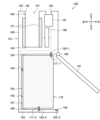
- FIG. 5 is a diagram for explaining the first modification.
- the suction device 100 according to this modification has a hinge mechanism 168 that rotates the lid portion 161.
- the lid portion 161 may open and close the opening 164 by rotating.
- the opening/closing sensor 185-1 may be omitted and only the opening/closing sensor 185-2 may be disposed.
- the control circuit 180 may determine that the lid portion 161 is closed when the opening/closing sensor 185-2 detects the proximity to the lid portion 161, and may determine that the lid portion 161 is open when the opening/closing sensor 185-2 detects the separation from the lid portion 161.
- the mechanism by which the lid portion 161 opens and closes the opening 164 is not limited to attachment/detachment and rotation.
- the lid portion 161 may open and close the opening 164 by other actions, such as sliding.
- FIG. 6 is a diagram for explaining the second modification. As shown in Fig. 6, the positions of the control circuit 180, the charging circuit 181, and the charging terminal 182, and the positions of the storage section 140 and the heating section 121 in the left-right direction may be reversed from those of the embodiment described with reference to Figs. 2 to 4.
- the battery terminal 183-1 may be disposed on the left inner wall 167 of the battery chamber 162, or may be connected to the electrode 171-1 disposed on the right side of the battery pack 170.
- the distance between the electrode 171-1 and the battery terminal 183-1 and the heating unit 121 can be made longer than when the battery terminal 183-1 is disposed on the upper inner wall 165 of the battery chamber 162.
- the battery terminal 183-2 may be disposed on the left inner wall 167 of the battery chamber 162, or may be connected to the electrode 171-2 disposed on the right side of the battery pack 170.
- the battery terminal 183 When the battery terminal 183 is disposed on the left inner wall 167 of the battery chamber 162, the battery terminal 183 and the battery pack 170 come into contact with each other only when the battery pack 170 is inserted all the way. This prevents friction between the battery terminals 183 and the battery pack 170 when the battery pack 170 is inserted or removed, making it possible to suppress deterioration of the battery terminals 183.
- the positions of the components of the suction device 100 are not limited to the examples shown in Figures 2 to 4 or the example shown in Figure 6, and can be changed as appropriate.
- FIG. 7 is a diagram for explaining the third modification.
- the suction device 100 may have a plurality of temperature sensors 184 (184-1 to 184-5).
- the control circuit 180 may control the operation of the heating unit 121 based on the highest temperature among the temperatures detected by the plurality of temperature sensors 184.
- At least one temperature sensor 184-5 is arranged in the central portion 179 in the vertical direction of the surface of the battery pack 170.
- the charging circuit 181 may also control the charging of the battery pack 170 based on the highest temperature among the temperatures detected by the plurality of temperature sensors 184. This makes it possible to operate the battery pack 170 at a more appropriate temperature.
- FIG. 8 is a diagram for explaining an example of an air flow path in the inhalation device 100.
- the configuration of the inhalation device 100 shown in FIG. 8 is as described with reference to FIGS. 3 and 4.
- This type of air flow is also called a counterflow.
- FIG. 9 is a diagram for explaining another example of an air flow path in the inhalation device 100.
- the inhalation device 100 shown in FIG. 9 is provided with a first through hole 104 having both ends, the bottom 143 of the storage section 140 and the upper inner wall 165 of the battery chamber 162.
- the first through hole 104 connects the internal space 141 of the storage section 140 and the internal space 163 of the battery chamber 162.
- the inhalation device 100 is provided with a second through hole 105 having both ends, the lower inner wall 166 of the battery chamber 162 and the bottom surface 103 of the inhalation device 100.
- the second through hole 105 connects the internal space 163 of the battery chamber 162 to the outside.
- FIG. 9 is a diagram for explaining another example of an air flow path in the inhalation device 100.
- the partition 107 can isolate the temperature sensor 184 from the air flow path 190-2. As a result, it is possible to prevent a situation in which cold air from the outside that flows into the battery chamber 162 due to a puff comes into contact with the temperature sensor 184, causing an inappropriate drop in the temperature detected by the temperature sensor 184.
- FIG. 10 is a diagram for explaining another example of an air flow path in the inhalation device 100.
- the inhalation device 100 shown in FIG. 10 is provided with a third through hole 106 whose two ends are the bottom 143 of the storage section 140 and the side surface of the inhalation device 100.
- the inhalation device 100 is an example of an aerosol generating system that generates an aerosol by heating an aerosol source.
- the battery pack 170 is configured to be detachable from the inhalation device 100.
- the main body 101 of the inhalation device 100 excluding the battery pack 170 may be regarded as the aerosol generating system, or the entire inhalation device 100 including the battery pack 170 may be regarded as the aerosol generating system.
- a combination of the inhalation device 100 and the stick-type substrate 150 may be regarded as the aerosol generating system.
- the heating unit 121 described above is an example of a load that generates energy for heating the aerosol source contained in the stick-shaped substrate 150 housed in the housing unit 140.
- the load may be a resistive heating type heating unit 121 as described above.
- an electromagnetic induction source such as an induction coil corresponds to the load.
- the direction in which the stick-shaped substrate 150 is inserted or removed and the direction in which the battery pack 170 is inserted or removed may be perpendicular to each other, but the present disclosure is not limited to such an example.
- the direction in which the stick-shaped substrate 150 is inserted or removed and the direction in which the battery pack 170 is inserted or removed may be approximately perpendicular to each other.
- the charging terminal 182 may be provided on a side of the battery pack 170.
- the heating unit 121 is provided on the left side, it is desirable for the charging terminal 182 to be provided on the right side, which is the opposite side to the heating unit 121. With such a configuration, it is also possible to suppress heat transfer from the heating unit 121 to the charging terminal 182.
- the temperature sensor 184 may be disposed inside the lid portion 161, which is the inner wall of the battery chamber 162 on the side in the direction in which the battery pack 170 is removed.
- the temperature sensor 184 and the battery pack 170 come into contact only when the battery pack 170 is inserted all the way and the lid portion 161 is closed. This prevents friction between the temperature sensor 184 and the battery pack 170 that occurs when the battery pack 170 is inserted and removed, making it possible to suppress misalignment and failure of the temperature sensor 184.
- the present disclosure is not limited to such an example.
- the inner wall of the internal space 163 does not necessarily have to be flat, and may be curved.
- the series of processes performed by each device described in this specification may be realized using software, hardware, or a combination of software and hardware.
- the programs constituting the software are stored in advance, for example, in a recording medium (more specifically, a non-transient storage medium readable by a computer) provided inside or outside each device.
- Each program is loaded into a RAM when executed by a computer that controls each device described in this specification, and executed by a processing circuit such as a CPU.
- the recording medium is, for example, a magnetic disk, an optical disk, a magneto-optical disk, a flash memory, etc.
- the computer program may be distributed, for example, via a network without using a recording medium.
- the computer may be an application-specific integrated circuit such as an ASIC, a general-purpose processor that executes functions by reading a software program, or a computer on a server used in cloud computing.
- ASIC application-specific integrated circuit
- ASIC general-purpose processor
- the series of processes performed by each device described in this specification may be centrally processed by a single computer, or may be distributed and processed by multiple computers.
- two or more communication means present in one device may be physically realized by one medium.
- a first container that contains a substrate containing an aerosol source; A load that generates energy for heating an aerosol source contained in the substrate contained in the first container; A second housing portion housing a battery that supplies power to the load; a temperature sensor disposed in the second housing portion and configured to measure a temperature of the battery housed in the second housing portion; A control unit that controls an operation of the load based on the temperature detected by the temperature sensor; Equipped with the first accommodating portion has a first opening and accommodates the base material in a removable manner so that the base material is inserted in a first direction and removed in a second direction through the first opening; the second storage portion has a second opening and stores the battery in a removable manner so that the battery is inserted in a third direction and removed in a fourth direction through the second opening; The temperature sensor is disposed on an inner wall of the second housing portion on the third direction side or the fourth direction side.
- Aerosol generation systems (2) The temperature sensor is disposed adjacent to a portion of the surface of the battery that is expected to become hottest during operation of the load. The aerosol generating system described in (1) above. (3) The temperature sensor is disposed on a surface of the battery so as to be adjacent to a side closer to the load than a center of the battery. The aerosol generating system described in (2) above. (4) the control unit estimates a maximum temperature of the battery based on the temperature detected by the temperature sensor, and controls an operation of the load based on the estimated maximum temperature of the battery. The aerosol generation system described in any one of (1) to (3).
- the aerosol generation system includes a plurality of the temperature sensors, The control unit controls the operation of the load based on the highest temperature among the temperatures detected by the plurality of temperature sensors.
- the second storage section further includes a lid section that opens and closes the second opening, The cover opens and closes the second opening by being attached/detached or rotated.
- the aerosol generation system further includes an opening/closing sensor that detects opening and closing of the second opening by the lid portion, The control unit controls the operation of the load based on a detection result by the open/close sensor.
- the control unit controls charging of the battery based on a detection result by the open/close sensor.
- the aerosol generation system includes a terminal electrically connected to the battery;
- the control unit is disposed on the second direction side of the second storage unit, the terminal is disposed on an inner wall of the second housing portion on the second direction side at a position offset from the load in the third direction or the fourth direction.
- the aerosol generation system includes a terminal electrically connected to the battery;
- the terminal is configured as an elastic body.
- the aerosol generating system comprises: a first through hole communicating an internal space of the first housing portion with an internal space of the second housing portion; A second through hole that communicates an internal space of the second housing portion with the outside; Further comprising: The aerosol generation system described in any one of (1) to (10).
- the aerosol generating system comprises: a charging terminal for receiving power for charging the battery supplied from an external power source; The charging terminal is disposed on the second direction side of the second housing portion.
- the first direction and the second direction are perpendicular or substantially perpendicular to the third direction and the fourth direction.
- the aerosol generation system further comprises the battery.
- the aerosol generating system further comprises the substrate.
- Suction device 101 Main body 102 Top surface 103 Bottom surface 104 First through hole 105 Second through hole 106 Third through hole 107 Partition wall 111 Power supply unit 112 Sensor unit 113 Notification unit 114 Memory unit 115 Communication unit 116 Control unit 121 Heating unit 140 Storage unit 141 Internal space 142 Opening 143 Bottom 150 Stick-shaped substrate 151 Substrate unit 152 Suction port unit 160 Housing 161 Lid unit 162 Battery chamber 163 Internal space 164 Opening 165 Upper inner wall 166 Lower inner wall 167 Left inner wall 168 Hinge mechanism 170 Battery pack 171 Electrode 180 Control circuit 181 Charging circuit 182 Charging terminal 183 Battery terminal 184 Temperature sensor 185 Open/close sensor 190 Air flow path
Landscapes
- Engineering & Computer Science (AREA)
- Power Engineering (AREA)
- Battery Mounting, Suspending (AREA)
- Secondary Cells (AREA)
Priority Applications (5)
| Application Number | Priority Date | Filing Date | Title |
|---|---|---|---|
| JP2025509393A JP7900598B2 (ja) | 2023-03-29 | 2023-03-29 | エアロゾル生成システム |
| CN202380095731.6A CN120787125A (zh) | 2023-03-29 | 2023-03-29 | 气溶胶产生系统 |
| PCT/JP2023/012805 WO2024201777A1 (ja) | 2023-03-29 | 2023-03-29 | エアロゾル生成システム |
| KR1020257030046A KR20250137201A (ko) | 2023-03-29 | 2023-03-29 | 에어로졸 생성 시스템 |
| EP23930417.3A EP4681566A1 (en) | 2023-03-29 | 2023-03-29 | Aerosol generation system |
Applications Claiming Priority (1)
| Application Number | Priority Date | Filing Date | Title |
|---|---|---|---|
| PCT/JP2023/012805 WO2024201777A1 (ja) | 2023-03-29 | 2023-03-29 | エアロゾル生成システム |
Publications (1)
| Publication Number | Publication Date |
|---|---|
| WO2024201777A1 true WO2024201777A1 (ja) | 2024-10-03 |
Family
ID=92903615
Family Applications (1)
| Application Number | Title | Priority Date | Filing Date |
|---|---|---|---|
| PCT/JP2023/012805 Ceased WO2024201777A1 (ja) | 2023-03-29 | 2023-03-29 | エアロゾル生成システム |
Country Status (5)
| Country | Link |
|---|---|
| EP (1) | EP4681566A1 (cg-RX-API-DMAC7.html) |
| JP (1) | JP7900598B2 (cg-RX-API-DMAC7.html) |
| KR (1) | KR20250137201A (cg-RX-API-DMAC7.html) |
| CN (1) | CN120787125A (cg-RX-API-DMAC7.html) |
| WO (1) | WO2024201777A1 (cg-RX-API-DMAC7.html) |
Cited By (2)
| Publication number | Priority date | Publication date | Assignee | Title |
|---|---|---|---|---|
| WO2026099111A1 (en) * | 2024-11-06 | 2026-05-15 | Jt International Sa | Aerosol generation device and method |
| WO2026140101A1 (ja) * | 2024-12-25 | 2026-07-02 | 日本たばこ産業株式会社 | 香味吸引器および香味吸引システム |
Citations (5)
| Publication number | Priority date | Publication date | Assignee | Title |
|---|---|---|---|---|
| JP2013150593A (ja) * | 2011-08-25 | 2013-08-08 | Kazuhiko Shimizu | 無煙喫煙治具 |
| CN107373765A (zh) | 2017-08-15 | 2017-11-24 | 深圳葆威道科技有限公司 | 一种新型的烤烟电子烟 |
| US20190166914A1 (en) * | 2016-07-19 | 2019-06-06 | Joyetech Europe Holding Gmbh | Electronic cigarette and temperature warning method thereof |
| JP2021182915A (ja) * | 2018-10-26 | 2021-12-02 | 日本たばこ産業株式会社 | 香味生成装置 |
| WO2022239390A1 (ja) * | 2021-05-10 | 2022-11-17 | 日本たばこ産業株式会社 | エアロゾル生成装置の電源ユニット |
-
2023
- 2023-03-29 KR KR1020257030046A patent/KR20250137201A/ko active Pending
- 2023-03-29 EP EP23930417.3A patent/EP4681566A1/en active Pending
- 2023-03-29 CN CN202380095731.6A patent/CN120787125A/zh active Pending
- 2023-03-29 WO PCT/JP2023/012805 patent/WO2024201777A1/ja not_active Ceased
- 2023-03-29 JP JP2025509393A patent/JP7900598B2/ja active Active
Patent Citations (5)
| Publication number | Priority date | Publication date | Assignee | Title |
|---|---|---|---|---|
| JP2013150593A (ja) * | 2011-08-25 | 2013-08-08 | Kazuhiko Shimizu | 無煙喫煙治具 |
| US20190166914A1 (en) * | 2016-07-19 | 2019-06-06 | Joyetech Europe Holding Gmbh | Electronic cigarette and temperature warning method thereof |
| CN107373765A (zh) | 2017-08-15 | 2017-11-24 | 深圳葆威道科技有限公司 | 一种新型的烤烟电子烟 |
| JP2021182915A (ja) * | 2018-10-26 | 2021-12-02 | 日本たばこ産業株式会社 | 香味生成装置 |
| WO2022239390A1 (ja) * | 2021-05-10 | 2022-11-17 | 日本たばこ産業株式会社 | エアロゾル生成装置の電源ユニット |
Non-Patent Citations (1)
| Title |
|---|
| See also references of EP4681566A1 |
Cited By (2)
| Publication number | Priority date | Publication date | Assignee | Title |
|---|---|---|---|---|
| WO2026099111A1 (en) * | 2024-11-06 | 2026-05-15 | Jt International Sa | Aerosol generation device and method |
| WO2026140101A1 (ja) * | 2024-12-25 | 2026-07-02 | 日本たばこ産業株式会社 | 香味吸引器および香味吸引システム |
Also Published As
| Publication number | Publication date |
|---|---|
| KR20250137201A (ko) | 2025-09-17 |
| CN120787125A (zh) | 2025-10-14 |
| JP7900598B2 (ja) | 2026-08-04 |
| EP4681566A1 (en) | 2026-01-21 |
| JPWO2024201777A1 (cg-RX-API-DMAC7.html) | 2024-10-03 |
Similar Documents
| Publication | Publication Date | Title |
|---|---|---|
| US12063974B2 (en) | Flavor generation device, method of controlling flavor generation device, and program | |
| EP4681566A1 (en) | Aerosol generation system | |
| TW202027633A (zh) | 氣溶膠生成系統及其運轉方法 | |
| CN112203532A (zh) | 香味生成装置 | |
| JP2023513703A (ja) | エアロゾル生成装置及びそれを制御する方法 | |
| US20240206562A1 (en) | Aerosol-generating device | |
| WO2024157468A1 (ja) | エアロゾル生成システム | |
| JP7578721B2 (ja) | 吸引装置、制御方法、及びプログラム | |
| US20250009016A1 (en) | Aerosol-generating device | |
| WO2024194928A1 (ja) | エアロゾル生成システム、及び制御方法 | |
| WO2025126399A1 (ja) | エアロゾル生成装置 | |
| WO2025126395A1 (ja) | エアロゾル生成装置の電源ユニット | |
| JP7826228B2 (ja) | 吸引装置、表示方法、及びプログラム | |
| WO2025126391A1 (ja) | エアロゾル生成装置の電源ユニット | |
| WO2025126394A1 (ja) | エアロゾル生成装置の電源ユニット | |
| WO2025126392A1 (ja) | エアロゾル生成装置の電源ユニット | |
| EP4674298A1 (en) | Power supply unit of aerosol generation device, control method, and control program | |
| WO2025126400A1 (ja) | エアロゾル生成装置 | |
| EP4635342A1 (en) | Inhalation device, control method, and program | |
| CN120882332A (zh) | 气溶胶生成装置 | |
| WO2025126397A1 (ja) | エアロゾル生成装置 | |
| KR20250021043A (ko) | 에어로졸 생성 장치 | |
| WO2025022533A1 (ja) | エアロゾル生成システム、制御方法及びプログラム | |
| WO2024241484A1 (ja) | エアロゾル生成システム | |
| KR20250150632A (ko) | 하우징부, 에어로졸 생성 장치, 및 방법 |
Legal Events
| Date | Code | Title | Description |
|---|---|---|---|
| 121 | Ep: the epo has been informed by wipo that ep was designated in this application |
Ref document number: 23930417 Country of ref document: EP Kind code of ref document: A1 |
|
| ENP | Entry into the national phase |
Ref document number: 2025509393 Country of ref document: JP Kind code of ref document: A |
|
| WWE | Wipo information: entry into national phase |
Ref document number: 2025509393 Country of ref document: JP |
|
| WWE | Wipo information: entry into national phase |
Ref document number: 202380095731.6 Country of ref document: CN |
|
| WWE | Wipo information: entry into national phase |
Ref document number: 2023930417 Country of ref document: EP |
|
| WWP | Wipo information: published in national office |
Ref document number: 202380095731.6 Country of ref document: CN |
|
| NENP | Non-entry into the national phase |
Ref country code: DE |
|
| ENP | Entry into the national phase |
Ref document number: 2023930417 Country of ref document: EP Effective date: 20251013 |
|
| ENP | Entry into the national phase |
Ref document number: 2023930417 Country of ref document: EP Effective date: 20251013 |
|
| ENP | Entry into the national phase |
Ref document number: 2023930417 Country of ref document: EP Effective date: 20251013 |
|
| ENP | Entry into the national phase |
Ref document number: 2023930417 Country of ref document: EP Effective date: 20251013 |
|
| ENP | Entry into the national phase |
Ref document number: 2023930417 Country of ref document: EP Effective date: 20251013 |