WO2024201719A1 - 映像音響分離装置、方法、およびプログラム - Google Patents
映像音響分離装置、方法、およびプログラム Download PDFInfo
- Publication number
- WO2024201719A1 WO2024201719A1 PCT/JP2023/012536 JP2023012536W WO2024201719A1 WO 2024201719 A1 WO2024201719 A1 WO 2024201719A1 JP 2023012536 W JP2023012536 W JP 2023012536W WO 2024201719 A1 WO2024201719 A1 WO 2024201719A1
- Authority
- WO
- WIPO (PCT)
- Prior art keywords
- audio
- image feature
- video
- image
- acoustic
- Prior art date
- Legal status (The legal status is an assumption and is not a legal conclusion. Google has not performed a legal analysis and makes no representation as to the accuracy of the status listed.)
- Ceased
Links
Images


Classifications
-
- H—ELECTRICITY
- H04—ELECTRIC COMMUNICATION TECHNIQUE
- H04N—PICTORIAL COMMUNICATION, e.g. TELEVISION
- H04N5/00—Details of television systems
- H04N5/76—Television signal recording
- H04N5/91—Television signal processing therefor
- H04N5/92—Transformation of the television signal for recording, e.g. modulation, frequency changing; Inverse transformation for playback
Definitions
- the present invention relates to a video/audio separation device, method, and program that receives as input a video containing multiple objects, such as musical instruments, and corresponding audio signals, and obtains audio signals from different directions emitted by the multiple objects.
- Non-Patent Document 1 In recent years, there has been an increasing need to not only separate monaural sound sources, but also to localize the separated sound sources to objects in the image and manage video and audio in an integrated manner. As a result, a monaural sound source separation technology has been proposed in which audio corresponding to individual objects included in the video is separated from the video and monaural audio, respectively, as in Non-Patent Document 1.
- Ambisonics a sound recording and playback method called Ambisonics is being put into practical use, which uses four microphones arranged on the vertices of a regular tetrahedron and can capture sound from different directions, although the resolution is low.
- Non-Patent Document 1 inputs an image that features only a single instrument into a pre-trained neural net, and separates only the audio spectrogram corresponding to that instrument from the mono audio mixed with multiple instrument sounds.
- This technology restores the spatial audio by 1) using an audio neural net to separate the mono audio signal into multiple sound sources, 2) using a video neural net to divide the video into multiple small regions, calculates gains to be multiplied by the multiple sound sources for each small region, and 3) multiplies the multiple sound sources by the gains to generate audio corresponding to each small region.
- the instrument player When a performance scene is recorded with a spherical camera, the instrument player will only be present in a specific area of the image.
- the gain output by the technology described in Non-Patent Document 1 will ideally be a tensor in which only the elements corresponding to the small area of the player take nonzero values, with the other elements being zero. Also, even when focusing on each small area, if sound source separation is ideally achieved, only specific channels will take nonzero values, and the other elements will be zero. In other words, the ideal state is for the above gain tensor to have nonzero components in only a very small number of elements.
- the present invention has been made in consideration of these circumstances, and aims to provide a video and audio separation device, method, and program that improves sound source separation performance while increasing the sparsity of the gain tensor output from a spherical image, without requiring additional training of a neural network.
- the video/audio separation device of the first aspect of the present invention includes an image feature calculation unit that converts image signals of multiple images that constitute a part or all of a video into image features, an audio feature calculation unit that converts audio signals corresponding to the images into audio features consisting of multiple individual sound sources, an image feature optimization unit that optimizes the image features based on the audio features and a specified target sound source and outputs optimal image features, and a directional audio synthesis unit that generates audio for different directions based on the audio features and the optimal image features.
- the first aspect of the present invention it is possible to minimize the error between the target sound source for each direction given as spatial sound and the output sound, thereby making it possible to improve the sound source separation performance without requiring additional learning of the neural network.
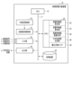
- FIG. 1 is a diagram showing an example of the electronic configuration of a video and audio separation device according to this embodiment.
- FIG. 2 is a diagram showing the flow of processing performed between each unit in the memory.
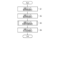
- FIG. 3 is a flowchart showing an example of the operation of the video and audio separation device according to this embodiment.
- FIG. 4 is a flowchart showing a detailed operation example of the image feature amount optimization unit.
- FIG. 1 is a diagram showing an example of the electronic configuration of a video/audio separation device according to this embodiment.
- the video/audio separation device 10 uses a sound source separation technology that receives an image signal a, which is a video signal containing multiple objects such as musical instruments, and a corresponding audio signal h as input, and obtains audio signals g for different directions emitted by the multiple objects.
- image signal a is a video signal containing multiple objects such as musical instruments, and a corresponding audio signal h as input, and obtains audio signals g for different directions emitted by the multiple objects.
- the electronic configuration of this video/audio separating device 10 includes a CPU 12, a recording medium reader 14, an input unit 16 that receives signals input to the video/audio separating device 10, an output unit 18 that outputs information generated by the video/audio separating device 10, a memory 20 in which various programs are stored, and a storage device 30, all of which are connected to one another via a bus 11.
- a video/audio separating device 10 can be realized, without being limited to this, as a PC or a tablet terminal. Alternatively, it does not necessarily have to be configured with the same hardware, and can be realized by multiple pieces of hardware with distributed functions, such as the cloud.
- the memory 20 stores programs for implementing image feature calculation processing, acoustic feature calculation processing, image feature optimization processing, and directional acoustic synthesis processing. That is, the image feature calculation unit 22, acoustic feature calculation unit 24, image feature optimization unit 26, and directional acoustic synthesis unit 28 are implemented by the programs stored in the memory 20.
- the CPU 12 is a computer that controls the operation of each of the units 22, 24, 26, and 28 according to the programs stored in the memory 20.
- the programs for these units 22, 24, 26, and 28 may be prestored in the memory 20, or may be read from an external recording medium 15, such as a memory card, via the recording medium reading unit 14 and stored in the memory 20.
- the programs for these units 22, 24, 26, and 28 cannot be rewritten.
- the memory 20 also has a writable data area 29 secured as an area for storing rewritable data. Furthermore, if the amount of data to be stored exceeds the capacity of the writable data area 29, the data may be stored in a storage device 30, such as a solid state drive (SSD) or hard disk drive (HDD).
- SSD solid state drive
- HDD hard disk drive
- Figure 2 shows the flow of processing between each part in the memory.
- the input unit 16 receives an image signal a of a plurality of images constituting all or part of a video.
- the input unit 16 also receives an audio signal h of sound corresponding to the images.
- the input unit 16 also receives a specified target sound source e.
- the input unit 16 outputs the input image signal a, audio signal h, and target sound source e to the memory 20.
- the image feature calculation unit 22 converts the image signal a output from the input unit 16 to the memory 20 into an image feature b.
- the acoustic feature calculation unit 24 converts the acoustic signal h output from the input unit 16 to the memory 20 into an acoustic feature d consisting of multiple individual sound sources.
- the acoustic signal h may be a monaural acoustic signal.
- the acoustic feature calculation unit 24 separates the acoustic signal h, which is a monaural acoustic signal, into sound sources of multiple channels and outputs each sound source as an acoustic feature d.
- the image feature optimization unit 26 optimizes the image feature b output from the image feature calculation unit 22 based on the acoustic feature d converted by the acoustic feature calculation unit 24 and the target sound source e output from the input unit 16 to the memory 20, to generate an optimal image feature f.
- the image feature optimization unit 26 can generate the optimal image feature f, for example, as follows:
- the image feature optimization unit 26 When outputting the optimal image feature f, the image feature optimization unit 26 stores a dual tensor with the same dimensions as the image feature b. Then, it performs a process of updating the dual tensor by applying a proximity operator to the weighted sum of the image feature b and the dual tensor.
- the image feature optimization unit 26 then updates the image feature b by the weighted sum of the tensor product calculated from the image feature b and the acoustic feature d, the gradient of the error norm with respect to the target sound source e, and the dual tensor.
- the image feature optimization unit 26 further performs convex projection on the updated image feature b to calculate the optimal image feature f.
- the image feature optimization unit 26 repeats this series of processes until the update width of the dual tensor falls below a predetermined threshold or the number of updates reaches a predetermined number, generating the optimal image feature f.
- the direction-specific sound synthesis unit 28 generates direction-specific sound g related to the sound feature d based on the sound feature d converted by the sound feature calculation unit 24 and the optimal image feature f generated by the image feature optimization unit 26.
- the acoustic signal h may also be an Ambisonics signal acquired by four or more microphones.
- the image feature calculation unit 22 sets multiple small regions for each of the multiple images based on the image signal a. Furthermore, for each of the multiple set small regions, the direction (elevation angle and azimuth angle) from the microphone used to acquire the Ambisonics signal is determined, and output as image feature b to the image feature optimization unit 26. The image feature b determined for each small region is used in the image feature optimization unit 26 as a gain to be multiplied by the individual sound source included in the acoustic feature d.
- the target sound source e is calculated for each small region from the Ambisonics signal. That is, the target sound source e calculated from the Ambisonics signal corresponds to each sound from the direction of each small region.
- the image feature optimization unit 26 can generate an optimal image feature f for each small region, for example, by using an optimization process that minimizes the error between the sound signal emitted from each small region and the target sound source e based on the image feature b and sound feature d.
- the directional sound synthesis unit 28 generates directional sound g from the sound emanating from each small region based on the sound feature d and the optimal image feature f.
- the output unit 18 outputs the direction-specific sound g generated by the direction-specific sound synthesis unit 28. Therefore, the output unit 18 can be realized as a speaker that outputs the sound g.
- the video/audio separating device 10 operates in cooperation with the hardware that constitutes the device 10, such as the bus 11, CPU 12, recording medium reader 14, input unit 16, output unit 18, memory 20, and storage device 30, and the software that is each program stored in memory 20.
- FIG. 3 is a flowchart showing an example of the operation of the video/audio separation device according to this embodiment.
- the acoustic feature calculation unit 24 outputs an acoustic feature d from the acoustic signal h.
- the acoustic feature d is, for example, a separated sound source S c (0 ⁇ c ⁇ C) obtained by separating the input monaural sound into one or more channels (here, C channel). Note that the 0th channel (W component) of the Ambisonics signal can be used for the monaural sound.
- a pre-trained neural network can be used to separate the sound source, but any method that separates into multiple sound sources may be used (S1).
- the image feature amount calculation unit 22 converts the image signal a of one or more images constituting a part or the whole of the video into an image feature amount b.
- the image feature amount b is, for example, composed of a total of C gains given to each of the sound sources of the multiple channels output by processing step 1 for each small region, and can be a tensor amount w kc having a dimension of K x C (0 ⁇ k ⁇ K).
- K is the number of small regions set in the image.
- the image feature amount calculation unit 22 may use a neural network that receives a video signal as an input and outputs the image feature amount b (S2).
- the image feature optimization unit 26 optimizes the image feature b using the sound sources of the multiple channels output by the acoustic feature calculation unit 24 and the input target sound source e, and outputs the optimized image feature f (S3).
- processing step 3 The operation of the image feature optimization unit 26, i.e., processing step 3, is explained in detail below.
- Figure 4 is a flowchart showing a detailed example of the operation of the image feature optimization unit.
- the image feature optimization unit 26 initializes a dual tensor, which is a tensor having the same dimensions as the image feature b. Uniform random numbers, etc. may be used for the initialization (S30).
- the image feature optimization unit 26 weights and adds the image feature b to the dual tensor, calculates a proximity operator for a convex conjugate function of the L1 norm as shown in the following equation, and outputs the updated dual tensor for each small region and each channel.
- the update step ⁇ 1 is a predetermined constant.
- a proximity operator for a convex function other than the L1 norm, such as the L21 norm may also be used as the proximity operator (S31).
- the image feature optimization unit 26 calculates an update difference from the image feature b, the tensor product of the sound sources of multiple channels from the acoustic feature calculation unit 24, and a weighted sum of the gradient and dual tensor of the L2 norm related to the error of the target sound source e, and calculates an intermediate image feature w'kc as shown in the following formula.
- the target sound source corresponding to the small region k is denoted by yk .
- the update step ⁇ 2 is a constant determined in advance (S32).
- the image feature optimization unit 26 calculates a convex projection of the intermediate image feature w'kc as shown in the following equation, and calculates an optimal image feature f for each small region and for each channel (S33).
- the image feature optimization unit 26 repeats processing steps 3-1 to 3-3 until a stopping condition is satisfied.
- the stopping condition can be satisfied when either the norm of the error between the updated dual tensor and the dual tensor before the update falls below a predetermined threshold value, or the number of iterations reaches a predetermined number (S34).
- the direction-specific sound synthesis unit 28 calculates the tensor product of the sound sources of the multiple channels output from the sound feature calculation unit 24 and the optimal image feature f output from the image feature optimization unit 26, as shown in the following equation, to generate direction-specific sound g related to the sound feature d (S4).
- the video and audio separation device to which the video and audio separation method according to this embodiment is applied can minimize the error between the target sound source for each direction given as spatial audio and the output audio, making it possible to improve the sound source separation performance without requiring additional learning of the neural network.
- the present invention is not limited to the above-described embodiment, and various modifications can be made in the implementation stage without departing from the gist of the invention.
- the above-described embodiment includes various inventions, and various inventions can be extracted by combinations selected from the multiple constituent elements disclosed. For example, if the problem can be solved and an effect can be obtained even if some constituent elements are deleted from all the constituent elements shown in the embodiment, the configuration from which these constituent elements are deleted can be extracted as an invention.
- Video/audio separation device 11 Bus 12 CPU 14 Recording medium reading section 15 External recording medium 16 Input section 18 Output section 20 Memory 22 Image feature amount calculation section 24 Acoustic feature amount calculation section 26 Image feature amount optimization section 28 Direction-specific sound synthesis section 29 Writable data area 30 Storage device a Image signal b Image feature amount d Acoustic feature amount e Target sound source f Optimized image feature amount g Direction-specific sound h Acoustic signal
Landscapes
- Engineering & Computer Science (AREA)
- Multimedia (AREA)
- Signal Processing (AREA)
- Stereophonic System (AREA)
Abstract
Description






11 バス
12 CPU
14 記録媒体読取部
15 外部記録媒体
16 入力部
18 出力部
20 メモリ
22 画像特徴量算出部
24 音響特徴量算出部
26 画像特徴量最適化部
28 方向別音響合成部
29 書込可能データエリア
30 記憶装置
a 画像信号
b 画像特徴量
d 音響特徴量
e 目標音源
f 最適画像特徴量
g 方向別の音響
h 音響信号
Claims (8)
- 映像の一部または全部を構成する複数の画像の画像信号を画像特徴量に変換する画像特徴量算出部と、
前記画像に対応する音響信号を、複数の個別音源からなる音響特徴量に変換する音響特徴量算出部と、
前記画像特徴量を、前記音響特徴量と、指定された目標音源とに基づいて最適化して、最適画像特徴量を出力する画像特徴量最適化部と、
前記音響特徴量と前記最適画像特徴量とに基づいて、方向別の音響を生成する方向別音響合成部と
を備えることを特徴とする、映像音響分離装置。 - 前記画像特徴量算出部は、前記複数の画像のおのおのに、複数の小領域を設定し、前記設定された複数の小領域それぞれに対し、前記音響特徴量に含まれる個別音源に乗じるゲインを、前記画像特徴量として出力することを特徴とする、請求項1に記載の映像音響分離装置。
- 前記画像特徴量算出部は、前記複数の画像のおのおのに、複数の小領域を設定し、
前記目標音源は、前記複数の小領域が存在する各方向からの音響であることを特徴とする、請求項1に記載の映像音響分離装置。 - 前記音響信号は、4つ以上のマイクによって取得されたアンビソニックス信号であり、
前記目標音源は、前記アンビソニックス信号を用いて計算されることを特徴とする、請求項1に記載の映像音響分離装置。 - 前記音響特徴量算出部は、前記音響信号がモノラル音響信号である場合、前記モノラル音響信号を、複数のチャンネルの音源に分離し、
前記音響特徴量は、前記複数のチャンネルに分離された各音源であることを特徴とする、請求項1に記載の映像音響分離装置。 - 前記画像特徴量最適化部は、
前記画像特徴量と同じ次元を持つ双対テンソルを内部に有し、前記画像特徴量と前記双対テンソルとの重み付き和に、近接作用素を適用することで、前記双対テンソルを更新する処理と、
前記画像特徴量と前記音響特徴量とによって計算されたテンソル積と、前記目標音源との誤差ノルムに関する勾配と、前記双対テンソルとの重み付き和によって、前記画像特徴量を更新する処理と、
前記更新された画像特徴量に対して凸射影を行い、前記最適画像特徴量を算出する処理とを、
前記双対テンソルの更新幅が、事前に決定された閾値を下回るか、あるいは更新回数が所定回数に達するまで繰り返す
ことを特徴とする、請求項1に記載の映像音響分離装置。 - 映像音響分離装置のプロセッサが、
映像の一部または全部を構成する複数の画像の画像信号を画像特徴量に変換するステップと、
前記画像に対応する音響の音響信号を、複数の個別音源からなる音響特徴量に変換するステップと、
前記画像特徴量を、前記音響特徴量と、指定された目標音源とに基づいて最適化して、最適画像特徴量を出力するステップと、
前記音響特徴量と前記最適画像特徴量とに基づいて、前記音響特徴量に関する方向別の音響を生成するステップと
を実行することを特徴とする、映像音響分離方法。 - 請求項1乃至6の何れか1項に記載の映像音響分離装置が備える各部として、コンピュータを機能させるためのプログラム。
Priority Applications (2)
| Application Number | Priority Date | Filing Date | Title |
|---|---|---|---|
| JP2025509341A JPWO2024201719A1 (ja) | 2023-03-28 | 2023-03-28 | |
| PCT/JP2023/012536 WO2024201719A1 (ja) | 2023-03-28 | 2023-03-28 | 映像音響分離装置、方法、およびプログラム |
Applications Claiming Priority (1)
| Application Number | Priority Date | Filing Date | Title |
|---|---|---|---|
| PCT/JP2023/012536 WO2024201719A1 (ja) | 2023-03-28 | 2023-03-28 | 映像音響分離装置、方法、およびプログラム |
Publications (1)
| Publication Number | Publication Date |
|---|---|
| WO2024201719A1 true WO2024201719A1 (ja) | 2024-10-03 |
Family
ID=92904321
Family Applications (1)
| Application Number | Title | Priority Date | Filing Date |
|---|---|---|---|
| PCT/JP2023/012536 Ceased WO2024201719A1 (ja) | 2023-03-28 | 2023-03-28 | 映像音響分離装置、方法、およびプログラム |
Country Status (2)
| Country | Link |
|---|---|
| JP (1) | JPWO2024201719A1 (ja) |
| WO (1) | WO2024201719A1 (ja) |
Citations (3)
| Publication number | Priority date | Publication date | Assignee | Title |
|---|---|---|---|---|
| US20210174817A1 (en) * | 2019-12-06 | 2021-06-10 | Facebook Technologies, Llc | Systems and methods for visually guided audio separation |
| US20210217182A1 (en) * | 2020-01-09 | 2021-07-15 | Yun Li | Single-channel and multi-channel source separation enhanced by lip motion |
| JP2022529553A (ja) * | 2019-04-25 | 2022-06-23 | インターナショナル・ビジネス・マシーンズ・コーポレーション | 敵対的生成ネットワークを用いた音声映像源分離および位置特定 |
-
2023
- 2023-03-28 JP JP2025509341A patent/JPWO2024201719A1/ja active Pending
- 2023-03-28 WO PCT/JP2023/012536 patent/WO2024201719A1/ja not_active Ceased
Patent Citations (3)
| Publication number | Priority date | Publication date | Assignee | Title |
|---|---|---|---|---|
| JP2022529553A (ja) * | 2019-04-25 | 2022-06-23 | インターナショナル・ビジネス・マシーンズ・コーポレーション | 敵対的生成ネットワークを用いた音声映像源分離および位置特定 |
| US20210174817A1 (en) * | 2019-12-06 | 2021-06-10 | Facebook Technologies, Llc | Systems and methods for visually guided audio separation |
| US20210217182A1 (en) * | 2020-01-09 | 2021-07-15 | Yun Li | Single-channel and multi-channel source separation enhanced by lip motion |
Also Published As
| Publication number | Publication date |
|---|---|
| JPWO2024201719A1 (ja) | 2024-10-03 |
Similar Documents
| Publication | Publication Date | Title |
|---|---|---|
| JP7517500B2 (ja) | 再生装置、再生方法、およびプログラム | |
| US11132984B2 (en) | Automatic multi-channel music mix from multiple audio stems | |
| US10595144B2 (en) | Method and apparatus for generating audio content | |
| JP7597133B2 (ja) | 再生装置、再生方法、およびプログラム | |
| JP5773960B2 (ja) | 音響再生装置とその方法とプログラム | |
| CN118098260B (zh) | 一种语音信号处理方法及相关设备 | |
| WO2019116889A1 (ja) | 信号処理装置および方法、学習装置および方法、並びにプログラム | |
| EP3695617A1 (en) | Spatial audio signal processing | |
| JP2012509632A5 (ja) | オーディオ信号を変換するためのコンバータ及び方法 | |
| WO2019216414A1 (ja) | 音響プログラム、音響装置、および音響システム | |
| WO2016208406A1 (ja) | 音声処理装置および方法、並びにプログラム | |
| CN106165444A (zh) | 声场再现设备、方法和程序 | |
| CN111798866B (zh) | 音频处理网络的训练及立体声重构方法和装置 | |
| JPWO2020066681A1 (ja) | 情報処理装置および方法、並びにプログラム | |
| WO2022014326A1 (ja) | 信号処理装置および方法、並びにプログラム | |
| JP2012169895A (ja) | 多重極スピーカ群とその配置方法と、音響信号出力装置とその方法と、その方法を用いたアクティブノイズコントロール装置と音場再生装置と、それらの方法とプログラム | |
| KR102054116B1 (ko) | 맞춤형 무대 영상 제공 시스템 | |
| KR20220036210A (ko) | 영상의 음질을 향상시키는 디바이스 및 방법 | |
| JP6970366B2 (ja) | 音像再現装置、音像再現方法及び音像再現プログラム | |
| WO2022018828A1 (ja) | 応援支援方法、応援支援装置、およびプログラム | |
| US20250220375A1 (en) | Generating spatialized audio signals based on modal interpolation of impulse responses | |
| CN118135975A (zh) | 混响装置的训练方法、混响方法和混响装置的训练装置 | |
| CN117501359A (zh) | 传送系统、音输出方法及程序 | |
| JP2017092832A (ja) | 再生方法および再生装置 | |
| JP4645955B2 (ja) | 音声付動画データの作成方法 |
Legal Events
| Date | Code | Title | Description |
|---|---|---|---|
| 121 | Ep: the epo has been informed by wipo that ep was designated in this application |
Ref document number: 23930359 Country of ref document: EP Kind code of ref document: A1 |
|
| ENP | Entry into the national phase |
Ref document number: 2025509341 Country of ref document: JP Kind code of ref document: A |
|
| WWE | Wipo information: entry into national phase |
Ref document number: 2025509341 Country of ref document: JP |
|
| NENP | Non-entry into the national phase |
Ref country code: DE |
|
| 122 | Ep: pct application non-entry in european phase |
Ref document number: 23930359 Country of ref document: EP Kind code of ref document: A1 |