WO2024201697A1 - 回転電機の製造方法、および溶接治具セット - Google Patents
回転電機の製造方法、および溶接治具セット Download PDFInfo
- Publication number
- WO2024201697A1 WO2024201697A1 PCT/JP2023/012428 JP2023012428W WO2024201697A1 WO 2024201697 A1 WO2024201697 A1 WO 2024201697A1 JP 2023012428 W JP2023012428 W JP 2023012428W WO 2024201697 A1 WO2024201697 A1 WO 2024201697A1
- Authority
- WO
- WIPO (PCT)
- Prior art keywords
- pair
- welding jig
- wall
- hole
- conductor portions
- Prior art date
- Legal status (The legal status is an assumption and is not a legal conclusion. Google has not performed a legal analysis and makes no representation as to the accuracy of the status listed.)
- Ceased
Links
Images







Classifications
-
- H—ELECTRICITY
- H02—GENERATION; CONVERSION OR DISTRIBUTION OF ELECTRIC POWER
- H02K—DYNAMO-ELECTRIC MACHINES
- H02K15/00—Processes or apparatus specially adapted for manufacturing, assembling, maintaining or repairing of dynamo-electric machines
- H02K15/08—Forming windings by laying conductors into or around core parts
- H02K15/085—Forming windings by laying conductors into or around core parts by laying conductors into slotted stators
Definitions
- An embodiment of the present invention relates to a manufacturing method for a rotating electric machine and a welding jig set.
- rotating electrical machines such as motors and generators are provided with a coil wound around a core.
- the coil is formed by winding copper wire multiple times, which means it has little flexibility, and inserting the formed coil into a slot in the core makes it extremely difficult to work with. For this reason, after multiple segments are inserted into the slots, laser light is irradiated onto the end of a segment and the end of an adjacent segment to form a coil wound around the core. In this case, if there is a gap between the ends of the segments, there is a risk that the weld cross-sectional area will be small or that the laser light will leak through the gap between the ends.
- a welding jig set includes a first welding jig with multiple first insertion holes and a second welding jig that is provided on the first welding jig and has multiple second insertion holes.
- the first and second insertion holes are provided with multiple pairs of inclined surfaces that are inclined in opposite directions. Therefore, when the first and second welding jigs are rotated in opposite directions, the inclined surfaces that move in the circumferential direction of the core push the ends of the segments that are located at overlapping positions in the circumferential direction of the core in a direction that brings them closer to each other in the radial direction of the core. This makes it possible to prevent gaps from occurring between the ends of the segments.
- the end of the segment is irradiated with laser light, spattering occurs, in which the heated segment material flies off. Therefore, if there is a large gap between the segment and the inner wall of the first insertion hole, and between the segment and the inner wall of the second insertion hole, the splattered hot segment material may pass through the gap and enter below the first welding tool and the second welding tool. Because the insulating parts of the segment are exposed below the first welding tool and the second welding tool, if the hot segment material comes into contact with the insulating parts, damage to the insulating parts may occur.
- the problem that this invention aims to solve is to provide a manufacturing method for a rotating electric machine and a welding jig set that can prevent gaps from occurring between the ends of the segments and prevent high-temperature material generated by sputtering from reaching the insulating parts of the segments.
- a manufacturing method for a rotating electric machine includes the steps of providing a segment having a conductor portion and an insulating portion provided on an outer surface of the conductor portion in each of a plurality of slots provided in a core, positioning ends of a pair of adjacent conductor portions using a first welding jig and a second welding jig provided on the first welding jig, and laser welding the positioned ends of the pair of conductor portions to form a coil provided in the slot.
- an end of a first conductor portion and an end of a second conductor portion adjacent to the first conductor portion are provided in positions that overlap in the circumferential direction of the core.
- the ends of the pair of adjacent conductor portions are inserted into a first hole provided in the first welding jig and a second hole provided in the second welding jig.
- first welding jig and the second welding jig are rotated in opposite directions, in a direction perpendicular to the radial direction of the core, the first inner wall of the first hole contacts the side of the first side of the pair of conductor parts, and the second inner wall of the second hole contacts the side of the second side facing the first side of the pair of conductor parts.
- a third inner wall intersecting with the first inner wall of the first hole contacts a part of the side of the third side intersecting with the side of the first side of the pair of conductor parts
- a fourth inner wall intersecting with the second inner wall of the second hole contacts a part of the side of the third side of the pair of conductor parts.
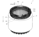
- FIG. 2 is a schematic perspective view for illustrating a stator.
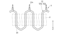
- FIG. 2 is a schematic diagram for illustrating a segment.
- 1A to 1C are schematic diagrams for illustrating the formation of a coil.
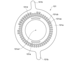
- FIG. 2 is a schematic plan view illustrating a welding jig.
- FIG. 2 is a schematic plan view illustrating a welding jig.
- 1 is a schematic perspective view illustrating a state in which a welding jig is used;
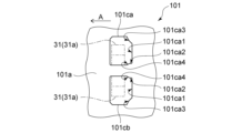
- FIG. 5A to 5C are schematic diagrams for illustrating the shapes of holes provided in a welding jig.
- 5A to 5C are schematic diagrams for illustrating the shapes of holes provided in a welding jig.
- 11A and 11B are schematic diagrams illustrating the positioning of ends of segments (conductor portions) by a welding jig according to a comparative example.
- 10 is a schematic diagram for illustrating the positioning of the ends of the segments (conductor portions) using a welding jig.
- FIG. 10 is a schematic perspective view illustrating an installation state of a welding cover.
- FIG. 2 is a schematic perspective view illustrating a welding cover.
- 11A to 11C are schematic diagrams illustrating a procedure for using the welding cover.
- 11A to 11C are schematic diagrams illustrating a procedure for using the welding cover.
- 11A to 11C are schematic diagrams illustrating a procedure for using the welding cover.
- 11A to 11C are schematic diagrams illustrating a procedure for using the welding cover.
- 11A to 11C are schematic diagrams illustrating a procedure for using the welding cover.
- FIG. 13 is a schematic plan view illustrating a welding jig according to another embodiment.
- FIG. 13 is a schematic plan view illustrating a welding jig according to another embodiment.
- FIG. 10 is a schematic diagram for illustrating the positioning of the ends of the segments (conductor portions) using a welding jig.
- FIG. 13 is a schematic perspective view illustrating an installation state of a welding jig according to another embodiment.
- FIG. 11 is a schematic perspective view for illustrating an end cover.
- FIG. FIG. 2 is a schematic perspective view illustrating a side cover.
- the method for manufacturing a rotating electric machine and the welding jig set according to this embodiment can be used, for example, when forming coils to be provided in rotating electric machines such as motors and generators.
- rotating electric machines such as motors and generators.
- the method for manufacturing a rotating electric machine and the welding jig set according to this embodiment are used to manufacture a stator.
- the method for manufacturing a rotating electric machine and the welding jig set according to this embodiment can also be used to manufacture other rotating electric machines.
- FIG. 1 is a schematic perspective view illustrating a stator 1. As shown in FIG. 1, a stator 1 is provided with a core 2 and a coil 3 .
- the core 2 is, for example, a stack of multiple annular magnetic members in the axial direction of the stator 1 (Z direction in FIG. 1).
- the magnetic members are, for example, made of electromagnetic steel sheets (silicon steel sheets).
- the core 2 has a yoke 21 and multiple teeth 22.
- the yoke 21 is cylindrical and located on the outer periphery of the core 2.
- the multiple teeth 22 are provided at equal intervals on the inner circumferential surface of the yoke 21.
- Each of the multiple teeth 22 protrudes from the inner circumferential surface of the yoke 21 toward the center of the core 2 and extends in the axial direction of the stator 1.
- grooves provided between the teeth 22 become slots 23.
- the shape, number, and size of the teeth 22 are not limited to those shown as examples, and can be changed as appropriate depending on the application, size, and specifications of the rotating electric machine in which the stator 1 is installed.
- the coil 3 includes a plurality of segments 31.
- the segments 31 have a conductor portion 31a and an insulating portion 31b (see, for example, FIG. 2).
- the conductor portion 31a is generally U-shaped and is formed from a material with high conductivity.
- the conductor portion 31a is formed from, for example, so-called pure copper or a material containing copper as a main component.
- the conductor portion 31a is formed from, for example, a rectangular wire.
- the rectangular wire is a wire material with a rectangular cross section.
- the insulating portion 31b covers the outer surface of the conductor portion 31a. However, the insulating portion 31b is not provided near the ends on both sides of the conductor portion 31a, and the conductor portion 31a is exposed.
- the insulating portion 31b includes, for example, enamel.
- a single coil 3 is formed by connecting multiple segments 31 via welds 31c. It is also possible to provide an insulating section that covers the exposed portion of the conductor portion 31a and the welds 31c.
- Terminal 31d is provided, for example, for applying power to coil 3.
- terminal 31e can be provided, which is electrically connected to the neutral points of multiple coils 3.
- Terminal 31d and terminal 31e each have, for example, a conductor portion 31a and an insulating portion 31b.
- the multiple coils 3 can be arranged side by side in the radial direction of the core 2 (a direction passing through the central axis of the core 2 and perpendicular to the Z direction).
- two coils 3 can be provided as illustrated in FIG. 1.
- the external shape, number, size, etc. of the coils 3 and the segments 31 are not limited to those illustrated, and can be changed as appropriate depending on the application, size, specifications, etc. of the rotating electric machine in which the stator 1 is provided.
- three coils 3 or four coils 3 can be provided in the radial direction of the core 2.
- the core 2 is formed.
- a plurality of plate-shaped magnetic members each having a yoke 21 and portions that will become a plurality of teeth 22 are formed.
- the magnetic members can be formed by punching an electromagnetic steel plate with a thickness of about 0.05 mm to 1.0 mm.
- the plurality of magnetic members are stacked, and the core 2 is formed by, for example, welding or crimping the plurality of magnetic members.
- the core 2 can also be formed by pressure molding a magnetic material powder and a resin binder.
- FIG. 2 is a schematic diagram illustrating the segment 31.
- a rectangular wire having a predetermined length is bent into an approximately U-shape to form the conductor portion 31a.
- a paint containing enamel or the like is applied to the outer surface of the conductor portion 31a to form the insulating portion 31b.
- a paint containing enamel or the like may be applied to the outer surface of the rectangular wire, which may then be cut to a predetermined length and bent into an approximately U-shape.
- a rectangular wire that has been enamel-painted or the like may be purchased, cut to a predetermined length, and bent into an approximately U-shape.
- the insulating portions 31b near both ends of the conductor portion 31a are peeled off to expose the conductor portion 31a. In this manner, a plurality of segments 31 are formed.
- FIG. 3 a segment 31 having a conductor portion 31a and an insulating portion 31b is provided in each of the multiple slots 23 provided in the core 2.
- each of the multiple segments 31 is inserted into a specific slot 23 from the axial direction of the core 2 (Z direction in Fig. 3).
- one segment 31 is inserted across the multiple slots 23.
- a so-called distributed winding coil 3 can be formed.
- a so-called wave winding coil 3 can be formed.
- insulating paper covering the segment 31 can be provided for each of the multiple slots 23.
- the portion of the segment 31 protruding from the core 2 is bent in a direction approaching the adjacent segment 31. Then, the vicinity of the portion of the conductor portion 31a exposed from the insulating portion 31b is further bent in the axial direction of the core 2 (Z direction in FIG. 3 ). In addition, the portion of the conductor portion 31a exposed from the insulating portion 31b and the portions of a pair of adjacent conductor portions 31a exposed from the insulating portion 31b are provided at positions that overlap in the circumferential direction of the core 2. The above procedure is then repeated to provide a plurality of sets of the segments 31 arranged in the circumferential direction of the core 2 in the radial direction of the core 2 .
- multiple segments 31 are fitted into slots 23 and then bent, this is not limiting.
- multiple segments 31 can be bent, and each of the multiple bent segments 31 can be fitted into a specific slot 23.
- the bent segments 31 can be fitted from the inside to the outside of the core 2.
- ends of adjacent segments 31 are laser welded to each other to form the coil 3 provided in the slot 23.
- a welded portion 31c is formed at the end of the laser welded conductor portion 31a.
- a single coil 3 is formed by connecting multiple segments 31 (conductor portions 31a) in series via the welded portions 31c.
- a plurality of coils 3 aligned in the radial direction of the core 2 are formed.
- the above-mentioned terminals 31d and 31e can be connected to the coil 3 by performing laser welding or the like.
- a welding jig 101 (corresponding to an example of a second welding jig) and a welding jig 102 (corresponding to an example of a first welding jig) are used to bring the ends of a pair of adjacent conductor portions 31a closer to each other in the radial direction of the core 2 (see FIG. 6).
- the welding jig 101 and the welding jig 102 will be described in detail later.
- the multiple coils 3 are fixed to the core 2.
- the coils 3 are fixed to the core 2 by supplying varnish into the gaps between the slots 23 and the coils 3 and hardening the varnish.
- varnish can be applied to the exposed portion of the conductor portion 31a of the coil 3 and to the welded portion 31c to form an insulating portion. If the varnish adheres to the ends, outer parts, inner parts, etc. of the core 2 when it is supplied, the varnish can be removed, for example, by irradiating the adhered varnish with laser light.
- FIG. 4 is a schematic plan view illustrating the welding jig 101.
- the welding jig 101 has a plate shape and includes a positioning portion 101a and a handle portion 101b.
- the contour of the positioning portion 101a may be, for example, an annular shape.
- the positioning portion 101a is provided with a plurality of holes 101ca, 101cb (corresponding to an example of a second hole) penetrating the positioning portion 101a in the thickness direction. Ends of a pair of segments 31 (conductor portions 31a) provided at overlapping positions in the circumferential direction of the core 2 are inserted into the plurality of holes 101ca, 101cb (see FIG. 6 ).
- the multiple holes 101ca can be arranged at equal intervals on a circle centered on the center 101a1 of the positioning portion 101a.
- the multiple holes 101cb can be arranged at equal intervals on a circle centered on the center 101a1 of the positioning portion 101a.
- the multiple holes 101cb are provided outside the multiple holes 101ca.
- the multiple holes 101ca, 101cb can be provided radially around the center 101a1 of the positioning portion 101a.
- the number of holes 101ca can be the same as the number of holes 101cb.
- the number of holes 101ca, 101cb can be the same as the number of segments 31 provided in one coil 3.
- the number of rows of holes 101ca and rows of holes 101cb can be the same as the number of coils 3 aligned in the radial direction of the core 2.
- the stator 1 illustrated in FIG. 1 has two coils 3 aligned in the radial direction of the core 2. Therefore, the positioning portion 101a illustrated in FIG. 4 has a row of holes 101ca and a row of holes 101cb aligned in the radial direction of the positioning portion 101a (radial direction of the core 2).
- the center-to-center distance between the holes 101ca and the holes 101cb can be the same as the center-to-center distance between the coils 3 aligned in the radial direction of the core 2.
- planar shape of holes 101ca and 101cb and the action and effect of holes 101ca and 101cb will be described in detail later.
- the planar shape of holes 101ca and 101cb is the shape of holes 101ca and 101cb when the welding jig 101 is viewed from the side opposite to the stator 1 side in FIG. 6.
- the positioning portion 101a may also be provided with a number of holes 101d penetrating the positioning portion 101a in the thickness direction.
- the number of holes 101d may be provided outside the row of holes 101cb.
- Terminals 31d and 31e are inserted into each of the number of holes 101d. Terminals 31d and 31e do not need to be positioned by the welding jig 101. Therefore, the planar dimensions of hole 101d are set to dimensions that prevent interference between the inner wall of hole 101d and terminals 31d and 31e when the conductor portion 31a is positioned by the welding jig 101 and welding jig 102.
- the positioning portion 101a may also be provided with a pair of holes 101e penetrating the thickness direction of the positioning portion 101a.
- the pair of holes 101e may be provided inside the row of holes 101ca.
- the pair of holes 101e are provided for fixing the welding jig 101 and the welding jig 102 with screws.
- the handle portion 101b is provided on the periphery of the positioning portion 101a.
- the handle portion 101b extends toward the outside of the positioning portion 101a.
- a pair of handle portions 101b may be provided.
- the pair of handle portions 101b may be provided radially from the center 101a1 of the positioning portion 101a.
- the handle portion 101b may be formed integrally with the positioning portion 101a.
- the welding jig 101 is made of a metal such as stainless steel.
- the thickness of the welding jig 101 is, for example, about 1 mm.
- FIG. 5 is a schematic plan view illustrating the welding jig 102.
- the welding jig 102 has a plate shape and includes a positioning portion 102a and a handle portion 102b.
- the positioning portion 102a and the handle portion 102b may be integrally formed.
- the material and thickness of the welding jig 102 may be the same as those of the welding jig 101.
- the shape and size of the positioning portion 102a can be the same as the shape and size of the positioning portion 101a.
- the shape and size of the handle portion 102b can be the same as the shape and size of the handle portion 102a.
- the positioning portion 102a is provided with a plurality of holes 102ca, 102cb (corresponding to an example of a first hole) penetrating the positioning portion 102a in the thickness direction. Ends of a pair of segments 31 (conductor portions 31a) provided at overlapping positions in the circumferential direction of the core 2 are inserted into each of the plurality of holes 102ca, 102cb (see FIG. 6). Therefore, the number and arrangement of the plurality of holes 102ca, 102cb can be the same as the number and arrangement of the plurality of holes 101ca, 101cb described above.
- the planar shapes of the holes 102ca and 102cb and the functions and effects of the holes 102ca and 102cb will be described in detail later.
- the positioning portion 102a may also be provided with a plurality of holes 102d penetrating the positioning portion 102a in the thickness direction.
- a terminal 31d or a terminal 31e is inserted into each of the plurality of holes 102d (see FIG. 6). Therefore, the number, arrangement, planar shape, and size of the plurality of holes 102d may be the same as the number, arrangement, planar shape, and size of the plurality of holes 101d described above.
- the positioning portion 102a may also be provided with a number of female screws 102e that penetrate the positioning portion 102a in the thickness direction. As described above, the welding jig 101 and the welding jig 102 are fixed using screws. Therefore, the multiple female screws 102e may be provided at positions that correspond to the holes 101e of the welding jig 101.
- FIG. 6 is a schematic perspective view illustrating the use state of welding jig 101 and welding jig 102.
- the ends of the plurality of segments 31 (conductor portions 31 a ) protruding from one end of the core 2 are inserted into the holes 102 ca and 102 cb of the welding jig 102 .
- the ends of the multiple segments 31 (conductor portions 31a) protruding from the holes 102ca, 102cb of the welding jig 102 are inserted into the holes 101ca, 101cb of the welding jig 101. That is, the welding jig 101 is provided on the welding jig 102.
- the welding jig 101 (positioning portion 101a) is rotated in a predetermined direction A (e.g., clockwise) via, for example, the handle portion 101b.
- the welding jig 102 (positioning portion 102a) is rotated in a direction B (e.g., counterclockwise) opposite to the welding jig 101 via, for example, the handle portion 102b.
- the ends of a pair of adjacent conductor portions 31a are pushed by the inner walls of the holes 101ca and 102ca in the radial direction of the core 2 and move toward each other.
- the ends of a pair of adjacent conductor portions 31a are pushed by the inner walls of the holes 101cb and 102cb in the radial direction of the core 2 and move toward each other.
- FIG. 7 is a schematic diagram illustrating the shapes of holes 101ca, 101cb provided in the welding jig 101.
- the hole 101cb has a shape that is a mirror image of the hole 101ca in the radial direction of the positioning portion 101a (the radial direction of the core 2). In this way, even if the inclined surface 101ca3 described later is lengthened, the distance between the holes 101ca and 101cb can be shortened. Note that, when the distance between the coils 3 arranged in the radial direction of the core 2 is long, the holes 101ca and 101cb may have the same shape.
- the hole 101ca has an inner wall 101ca1 (corresponding to an example of a second inner wall) that is approximately parallel to the line segment passing through the center 101a1 of the positioning portion 101a, and an inner wall 101ca2 (corresponding to an example of a fourth inner wall) that is approximately perpendicular to the inner wall 101ca1.
- the inner wall 101ca2 is connected to the end of the inner wall 101ca1 on the opposite side to the center 101a1 side of the positioning portion 101a.
- the inner wall 101ca1 can be the inner wall of the hole 101ca in the opposite direction to the direction A of the rotational movement of the welding jig 101.
- the length of the inner wall 101ca1 can be the same as or slightly longer than the total length when the ends of a pair of adjacent conductor portions 31a are overlapped. In other words, the inner wall 101ca1 can be in contact with the side surfaces of the pair of conductor portions 31a.
- the length of the inner wall 101ca2 can be shorter than the length of the end of the conductor portion 31a in a direction perpendicular to the radial direction of the positioning portion 101a (radial direction of the core 2).
- the length of the inner wall 101ca2 can be less than half the length of the end of the conductor portion 31a in a direction perpendicular to the radial direction of the positioning portion 101a (radial direction of the core 2).
- the inner wall 101ca2 can come into contact with a portion of the side surface of a pair of conductor portions 31a.
- the inner wall 101ca1 comes into contact with the end of the conductor portion 31a in a direction perpendicular to the radial direction of the core 2.
- the inner wall 101ca2 comes into contact with the end of the conductor portion 31a in the radial direction of the core 2.
- the inner wall 101ca1 and the inner wall 101ca2 serve as references when determining the position of the end of the conductor portion 31a.
- the inner wall 101ca1 has an inclined surface 101ca3 at the end opposite the inner wall 101ca2.
- the inclined surface 101ca3 is inclined in a direction approaching the center 101a1 of the positioning portion 101a as it moves away from the inner wall 101ca1.
- the inner wall 101ca2 has an inclined surface 101ca4 at the end opposite the inner wall 101ca1.
- the inclined surface 101ca4 is inclined in a direction away from the center 101a1 of the positioning portion 101a as it moves away from the inner wall 101ca2.
- the inclined surfaces 101ca3 and 101ca4 serve as guide surfaces for guiding the ends of a pair of adjacent conductor portions 31a to the inner walls 101ca1 and 101ca2. Note that the inclined surfaces 101ca3 and 101ca4 may be flat or curved.
- hole 101cb has a shape that is a mirror image of hole 101ca in the radial direction of positioning portion 101a (radial direction of core 2). Therefore, hole 101cb also has inner wall 101ca1, inner wall 101ca2, inclined surface 101ca3, and inclined surface 101ca4.
- inner walls 101ca1 and 101ca2 serve as references when determining the position of the end of conductor portion 31a.
- Inclined surfaces 101ca3 and 101ca4 serve as guide surfaces for guiding the ends of a pair of adjacent conductor portions 31a to inner walls 101ca1 and 101ca2.
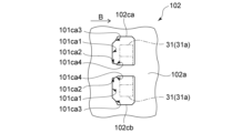
- FIG. 8 is a schematic diagram illustrating the shapes of holes 102ca, 102cb provided in the welding jig 102.
- the hole 102cb has a shape that is a mirror image of the hole 102ca in the radial direction of the positioning portion 102a (radial direction of the core 2). In this way, even if the inclined surface 101ca3 is lengthened, the distance between the holes 102ca and 102cb can be shortened. Note that, when the distance between the coils 3 arranged in the radial direction of the core 2 is long, the holes 102ca and 102cb may have the same shape.
- the hole 102ca has a shape that is a mirror image of the hole 101ca described above in a direction perpendicular to the radial direction of the positioning portion 102a (the radial direction of the core 2).
- hole 102ca also has inner wall 101ca1 (corresponding to an example of a first inner wall), inner wall 101ca2 (corresponding to an example of a third inner wall), inclined surface 101ca3, and inclined surface 101ca4. However, these are provided on the opposite side from hole 101ca in the direction perpendicular to the radial direction of positioning portion 102a (radial direction of core 2).
- the inner walls 101ca1 and 101ca2 serve as references for determining the position of the end of the conductor portion 31a.
- the inner wall 101ca1 can come into contact with the side surfaces of the pair of conductor portions 31a.
- the inner wall 101ca2 can come into contact with parts of the side surfaces of the pair of conductor portions 31a.
- the inclined surfaces 101ca3 and 101ca4 serve as guide surfaces for guiding the ends of a pair of adjacent conductor portions 31a to the inner walls 101ca1 and 101ca2.
- Hole 102cb has a shape that is a mirror image of hole 101cb described above in a direction perpendicular to the radial direction of positioning portion 102a (radial direction of core 2).
- the hole 102cb also has an inner wall 101ca1, an inner wall 101ca2, an inclined surface 101ca3, and an inclined surface 101ca4. However, these are provided on the opposite side to the hole 101cb in the direction perpendicular to the radial direction of the positioning portion 102a (the radial direction of the core 2).
- inner walls 101ca1 and 101ca2 serve as references when determining the position of the end of conductor portion 31a.
- Inclined surfaces 101ca3 and 101ca4 serve as guide surfaces for guiding the ends of a pair of adjacent conductor portions 31a to inner walls 101ca1 and 101ca2.
- FIG. 9 is a schematic diagram illustrating the positioning of the ends of the segments 31 (conductor portions 31a) by welding jigs 301 and 302 according to a comparative example.
- welding jig 301 is placed on welding jig 302.
- Welding jig 301 is rotated in direction A.
- Welding jig 302 is rotated in direction B opposite to direction A.
- Welding jig 301 is provided with hole 301a.
- the inner wall of hole 301a in the radial direction of core 2 is inclined surface 301b.
- Welding jig 302 is provided with hole 302a.
- the inner wall of hole 302a in the radial direction of core 2 is inclined surface 302b.
- the end of the conductor 31a When the end of the conductor 31a is irradiated with laser light, sputtering occurs, causing the heated material of the conductor 31a to fly off. Therefore, if there is a large gap between the conductor 31a and the inner walls 301c, 302c of the holes 301a, 302a, the high-temperature sputtered material of the conductor 31a may penetrate through the gap and into the area below the welding jigs 301, 302. Because the insulating portion 31b of the segment 31 is exposed below the welding jigs 301, 302, if the high-temperature sputtered material of the conductor 31a comes into contact with the insulating portion 31b, damage may occur to the insulating portion 31b.
- FIG. 10 is a schematic diagram illustrating the positioning of the ends of the segments 31 (the conductor portions 31a) by the welding jigs 101 and 102. As shown in FIG. When the ends of a pair of adjacent conductor portions 31a are positioned by the welding jigs 101 and 102, the inner wall 101ca1 of the hole 101ca (hole 101cb) and the inner wall 101ca1 of the hole 102ca (hole 102cb) come into contact with the conductor portion 31a, as shown in Fig. 10. Also, the inner wall 101ca2 of the hole 101ca (hole 101cb) and the inner wall 101ca2 of the hole 102ca (hole 102cb) come into contact with the conductor portion 31a.
- the welding jigs 101 and 102 of this embodiment can prevent gaps from occurring between the ends of the segments 31 (conductor portions 31a), and can prevent high-temperature material generated by sputtering from reaching the insulating portions 31b of the segments 31.
- the conductor portion 31a is sandwiched between a pair of inner walls 101ca1.
- the conductor portion 31a is pressed against a pair of inner walls 101ca2 by a pair of inclined surfaces 101ca3. Therefore, when determining the position of the end of the segment 31 (conductor portion 31a), it is possible to prevent misalignment between the conductor portions 31a and 31a.
- the hot material of the conductor 31a is scattered upward and falls toward the welding jigs 101 and 102. As a result, the scattered hot material of the conductor 31a reaches the vicinity of the conductor 31a undergoing laser welding.
- a welding cover 103 can be further provided on the welding jig 101.
- the welding cover 103 prevents the scattered high-temperature material of the conductor portion 31a from reaching the vicinity of the conductor portion 31a other than the conductor portion 31a that is the target of laser welding.
- Fig. 11 is a schematic perspective view illustrating an installation state of the welding cover 103.
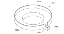
- Fig. 12 is a schematic perspective view illustrating the welding cover 103. 11 and 12, the welding cover 103 has, for example, an end cover 103a, a side cover 103b, and a peripheral cover 103c. The end cover 103a, the side cover 103b, and the peripheral cover 103c are integrally provided.
- the welding cover 103 can be made of a metal such as stainless steel.
- the contour of the end cover 103a can be, for example, annular.
- the end cover 103a covers the upper ends of a plurality of segments 31 (conductor portions 31a) arranged in the circumferential direction of the core 2.
- the end cover 103a has a notch 103a1 that opens to the periphery of the end cover 103a. Inside the notch 103a1, the ends of a pair of conductor portions 31a to be laser welded can be exposed.
- the inner peripheral side of the end cover 103a can cover the vicinity of the upper end of the insulating portion 31b exposed inside the core 2.
- a pair of side covers 103b are provided. Each of the pair of side covers 103b is provided at the opening position of the cutout 103a1.
- the pair of side covers 103b extend in the radial direction of the core 2. In the circumferential direction of the core 2, the side covers 103b are provided between adjacent conductor portions 31a.
- the conductor portions 31a located between the pair of side covers 103b are the target of laser welding.
- the peripheral cover 103c is provided on the peripheral edge of the end cover 103a.
- the peripheral cover 103c is not provided in the area of the end cover 103a where the notch 103a1 is provided.
- FIG. 13 to 16 are schematic diagrams illustrating the procedure for using the welding cover 103.
- FIG. 13 As shown in FIG. 13, first, the ends of the multiple segments 31 (conductor portions 31a) arranged in the circumferential direction of the core 2 are inserted into the holes 102ca (holes 102cb) of the welding jig 102.
- the welding jig 101 is placed on the welding jig 102, and the ends of the multiple segments 31 (conductor portions 31a) are inserted into the holes 101ca (holes 101cb) of the welding jig 101.
- the welding jig 101 and the welding jig 102 are rotated in opposite directions to position the ends of a pair of adjacent conductor portions 31a.
- the welding jig 101 and the welding jig 102 are fixed using screws.
- a welding cover 103 is placed on the welding jig 101.
- laser light L is irradiated to the inside of the cutout 103a1 of the end cover 103a and the ends of the pair of conductors 31a exposed between the pair of side covers 103b, to laser weld the ends of the pair of adjacent conductors 31a.
- spatter occurs.
- the material of the conductors 31a which has a high temperature, scatters upward and then falls toward the welding jigs 101, 102.
- the conductors 31a other than the conductors 31a to be laser welded are covered by the end cover 103a and the side covers 103b, it is possible to prevent the scattered material of the conductors 31a, which has a high temperature, from reaching the vicinity of the conductors 31a other than the conductors 31a to be laser welded.
- the inner periphery of the end cover 103a covers the vicinity of the upper end of the insulating portion 31b exposed to the inside of the core 2, so that the scattered high-temperature material of the conductor portion 31a can be prevented from reaching the insulating portion 31b exposed to the inside of the core 2.
- a peripheral cover 103c is provided on the periphery of the end cover 103a, which prevents the high-temperature material of the conductor portion 31a from flying around the periphery of the end cover 103a and reaching the insulating portion 31b.
- the material of the conductor portion 31a that is sputtered adheres to the surface of the welding cover 103, so the material of the conductor portion 31a that has adhered can be removed periodically or as needed.
- the welding cover 103 is lifted upward.
- the position of the core 2 or the welding cover 103 is shifted in the rotational direction so that the notch 103a1 of the end cover 103a and the space between the pair of side covers 103b are positioned above the pair of conductor parts 31a adjacent to the pair of conductor parts 31a that have been laser welded.
- the welding cover 103 is lowered and placed on the welding jig 101.
- the above-described procedure is then repeated to sequentially laser weld the ends of the multiple segments 31 (conductor portions 31a) that are aligned in the circumferential direction of the core 2.
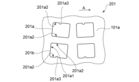
- FIG. 17 is a schematic plan view illustrating a welding jig 201 according to another embodiment.
- welding jig 201 (corresponding to an example of a second welding jig) is plate-shaped and has a positioning portion 101a and a handle portion 101b.
- Positioning portion 101a is provided with a plurality of holes 201a, 201b (corresponding to an example of a second hole) penetrating the thickness direction of positioning portion 101a. That is, welding jig 201 is obtained by replacing holes 101a, 101b of welding jig 101 with holes 201a, 201b. Therefore, only holes 201a, 201b are depicted in FIG. 17.
- each of the multiple holes 201a, 201b the ends of the multiple segments 31 (conductor portion 31a) protruding from holes 202a, 202b (corresponding to an example of a first hole) of a welding jig 202 (corresponding to an example of a first welding jig) described below are inserted.
- the arrangement of the multiple holes 201a can be the same as the arrangement of the multiple holes 101ca described above.
- the arrangement of the multiple holes 201b can be the same as the arrangement of the multiple holes 101cb described above.
- the hole 201a has an inner wall 201a1 (corresponding to an example of a second inner wall) that is approximately parallel to a line segment passing through the center 101a1 of the positioning portion 101a, and a pair of inner walls 201a2 (corresponding to an example of a fourth inner wall) that are approximately perpendicular to the inner wall 201a1.
- the distance between the pair of inner walls 201a2 can be the same as or slightly longer than the total length when the ends of a pair of adjacent conductor portions 31a are overlapped.
- the inner wall 201a1 comes into contact with the end of the conductor portion 31a in a direction perpendicular to the radial direction of the core 2. At least one of the pair of inner walls 201a2 comes into contact with the end of the conductor portion 31a in the radial direction of the core 2.
- the inner walls 201a1 and 201a2 serve as references when determining the position of the end of the conductor portion 31a.
- one of the pair of inner walls 201a2 may be provided with a protrusion 201a3 that protrudes into the hole 201a.
- the contour of the protrusion 201a3 may be, for example, a part of a circle.
- the distance between the protrusion 201a3 and the inner wall 201a1 may be the same as or slightly longer than the dimension of the end of the conductor portion 31a.
- the protrusion 201a3 prevents the position of the conductor portion 31a from moving away from the inner wall 201a1.
- Hole 201b has a shape that is a mirror image of hole 201a in the radial direction of positioning portion 101a (radial direction of core 2). Therefore, hole 201b also has an inner wall 201a1, a pair of inner walls 201a2, and a protrusion 201a3. Note that hole 201b may have the same shape as hole 201a.
- inner walls 201a1 and 201a2 serve as references when determining the position of the end of conductor portion 31a.
- Protrusion 201a3 is provided to prevent the position of conductor portion 31a from shifting.
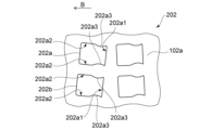
- FIG. 18 is a schematic plan view illustrating a welding jig 202 according to another embodiment. Similar to the above-described welding jig 102, the welding jig 202 is plate-shaped and has a positioning portion 102a and a handle portion 102b. The positioning portion 102a is provided with a plurality of holes 202a, 202b (corresponding to an example of a first hole) penetrating the positioning portion 102a in the thickness direction. That is, the welding jig 202 has holes 202a, 202b instead of holes 102ca, 102cb of the welding jig 102. Therefore, only holes 202a, 202b are depicted in FIG. 18.
- each of the multiple holes 202a, 202b the ends of a pair of segments 31 (conductor portions 31a) that are provided at overlapping positions in the circumferential direction of the core 2 are inserted.
- the arrangement of the multiple holes 202a can be the same as the arrangement of the multiple holes 102ca described above.
- the arrangement of the multiple holes 202b can be the same as the arrangement of the multiple holes 102cb described above.
- the hole 202a has an inner wall 202a1 (corresponding to an example of a first inner wall) that is approximately parallel to a line segment that passes through the center 102a1 of the positioning portion 102a, and a pair of inner walls 202a2 (corresponding to an example of a third inner wall and a fifth inner wall) that are approximately perpendicular to the inner wall 202a1.
- Each of the pair of inner walls 202a2 is provided with a protrusion 202a3 (corresponding to an example of a first convex region and a second convex region) that protrudes into the hole 202a.
- the contour of the protrusion 202a3 can be, for example, a part of a circle.
- the distance between the pair of protrusions 202a3 can be the same as or slightly longer than the total length when the ends of the pair of adjacent conductor parts 31a are overlapped.
- the pair of protrusions 202a3 sandwich the ends of the pair of conductor parts 31a so that the ends of the conductor parts 31a approach each other. In other words, when the ends of the pair of conductor parts 31a are positioned, the pair of conductor parts 31a are sandwiched between the protrusions 202a3 and the protrusions 202a3.
- the welding jig 202 is provided with a pair of protrusions 202a3, but the welding jig 201 may be provided with a pair of protrusions 202a3 (corresponding to an example of the third convex region and the fourth convex region).
- the welding jig 201 may be provided with a plurality of holes 202a, 202b, and the welding jig 202 may be provided with a plurality of holes 201a, 201b.
- the inner wall 202a1 comes into contact with the ends of the conductor portions 31a in a direction perpendicular to the radial direction of the core 2.
- the tops of the pair of protrusions 202a3 also come into contact with the ends of the conductor portions 31a in the radial direction of the core 2.
- the inner wall 202a1 and the tops of the pair of protrusions 202a3 serve as references when determining the position of the ends of the conductor portions 31a.
- Hole 202b has a shape that is a mirror image of hole 202a in the radial direction of positioning portion 102a (radial direction of core 2).
- hole 202b can have the same shape as hole 202a. That is, hole 202b has inner wall 202a1, a pair of inner walls 202a2, and a pair of protrusions 202a3.
- the functions of inner wall 202a1 and pair of protrusions 202a3 provided in hole 202b can be the same as those of hole 202a described above.
- FIG. 19 is a schematic diagram illustrating the positioning of the ends of the segments 31 (the conductor portions 31 a ) by the welding jigs 201 and 202 .
- the inner wall 201a1 of the hole 201a (hole 201b) and the inner wall 202a1 of the hole 202a (hole 202b) come into contact with the conductors 31a, as shown in Fig. 19.
- the tops of the pair of protrusions 202a3 come into contact with the conductors 31a (they come into contact with parts of the side surfaces of the pair of conductors 31a).
- the welding jigs 201 and 202 of this embodiment can prevent gaps from occurring between the ends of the segments 31 (conductor portions 31a), and can prevent high-temperature material generated by sputtering from reaching the insulating portions 31b of the segments 31.
- the conductor portion 31a is sandwiched between the inner wall 201a1 and the inner wall 202a1.
- the pair of conductor portions 31a is sandwiched between the tops of the pair of protrusions 202a3. Therefore, when determining the position of the end of the segment 31 (conductor portion 31a), it is possible to prevent misalignment between the conductor portions 31a.
- FIG. 20 is a schematic perspective view for illustrating an installation state of a welding jig 203 according to another embodiment.
- the welding jig 203 like the welding cover 103 described above, is provided to prevent the scattered material of the high-temperature conductor portion 31a from reaching the conductor portion 31a other than the conductor portion 31a that is to be laser welded.
- the welding jig 203 has an end cover 203a and a side cover 203b.
- the end cover 203a and the side cover 203b can be made of a metal such as stainless steel.
- the side cover 203b can be provided on the welding jig 201.
- the end cover 203a can be provided on the side cover 203b.
- the end cover 203a and the side cover 203b are provided separately.
- the end cover 203a can be in contact with the side cover 203b.
- the welding jigs 101, 102 and the welding jig 203 may be combined, or the welding jigs 201, 202 and the welding cover 103 may be combined.
- FIG. 21 is a schematic perspective view for illustrating the end cover 203a.
- the contour of the end cover 203a can be, for example, annular.
- the end cover 203a covers the upper ends of the multiple segments 31 (conductor portions 31a) arranged in the circumferential direction of the core 2.
- the end cover 203a has a notch 203a1 that opens on the periphery of the end cover 203a.
- the end of the conductor portion 31a to be laser-welded can be exposed below the notch 203a1.
- the end of the conductor portion 31a is not provided inside the notch 203a1. Therefore, the position of the end cover 203a in the rotation direction around the central axis of the core 2 can be arbitrarily changed.
- the inner periphery side of the end cover 203a can cover the vicinity of the upper end of the insulating portion 31b exposed inside the core 2.
- the peripheral cover 103c provided on the welding cover 103 described above can be further provided.
- FIG. 22 is a schematic perspective view for illustrating the side cover 203b.
- the contour of the side cover 203b may be, for example, an annular shape.
- the side cover 203b has a plurality of grooves 203b2 extending radially from a center 203b1.
- a hole 203b3 is provided in the bottom surface of each of the plurality of grooves 203b2.
- Ends of a plurality of segments 31 (conductor portions 31a) arranged in the circumferential direction of the core 2 are inserted into the hole 203b3.
- the ends of the segments 31 (conductor portions 31a) are provided inside the hole 203b3, but do not protrude from the upper surface of the side cover 203b (the surface opposite to the core 2 side).
- the ends of the multiple segments 31 (conductor portions 31a) arranged in the circumferential direction of the core 2 are inserted into the holes 202a (holes 202b) of the welding jig 202.
- the welding jig 201 is placed on the welding jig 202, and the ends of the multiple segments 31 (conductor portions 31a) are inserted into the holes 201a (holes 201b) of the welding jig 201.
- the welding jig 201 and the welding jig 202 are rotated in opposite directions to position the ends of a pair of adjacent conductor portions 31a.
- the welding jig 201 and the welding jig 202 are fixed together using screws.
- the side cover 203b is placed on the welding jig 201, and the ends of the multiple segments 31 (conductor portions 31a) are inserted into the holes 203b3 of the side cover 203b. Then, the end cover 203a is placed on top of the side cover 203b.
- the ends of the pair of conductors 31a exposed below the notches 203a1 of the end cover 203a are irradiated with laser light to laser weld the ends of the pair of adjacent conductors 31a.
- laser welding is performed, spattering occurs.
- the material of the conductors 31a with high temperature is scattered upward and falls toward the welding jigs 201 and 202.
- the conductors 31a other than the conductors 31a to be laser welded are covered by the end cover 203a and the side cover 203b, it is possible to prevent the scattered material of the conductors 31a with high temperature from reaching the vicinity of the conductors 31a other than the conductors 31a to be laser welded.
- the inner circumferential side of the end cover 203a covers the vicinity of the upper end of the insulating portion 31b exposed inside the core 2, it is possible to prevent the scattered material of the conductors 31a with high temperature from reaching the insulating portion 31b exposed inside the core 2.
- the material of the conductor portion 31a that is scattered by sputtering adheres to the surface of the welding jig 203, so the material of the conductor portion 31a that has adhered can be removed periodically or as needed.
- the position of the end cover 203a in the rotational direction is changed, and the ends of the pair of conductors 31a to be laser-welded next are exposed below the notches 203a1.
- the positions of the end cover 203a in the rotational direction can be changed without lifting the end cover 203a. This improves the workability of the laser welding.
- the ends of the multiple segments 31 (conductor portions 31a) arranged in the circumferential direction of the core 2 are sequentially laser-welded.
Landscapes
- Engineering & Computer Science (AREA)
- Manufacturing & Machinery (AREA)
- Power Engineering (AREA)
- Manufacture Of Motors, Generators (AREA)
Abstract
実施形態に係る回転電機の製造方法は、コアに設けられた複数のスロットのそれぞれに、導体部と、前記導体部の外面に設けられた絶縁部と、を有するセグメントを設ける工程と、第1の溶接治具と、前記第1の溶接治具の上に設けられる第2の溶接治具と、を用いて、隣接する一対の前記導体部の端部を位置決めする工程と、位置決めされた前記一対の導体部の端部をレーザ溶接して、前記スロットに設けられたコイルを形成する工程と、を備えている。前記セグメントを設ける工程において、第1の導体部の端部と、前記第1の導体部に隣接する第2の導体部の端部と、を前記コアの周方向において重なる位置に設ける。前記一対の導体部の端部を位置決めする工程において、前記第1の溶接治具に設けられた第1の孔と、前記第2の溶接治具に設けられた第2の孔と、に前記隣接する一対の前記導体部の端部を挿入する。前記第1の溶接治具と、前記第2の溶接治具と、を互いに逆方向に回転させた際に、前記コアの径方向に直交する方向において、前記第1の孔の第1の内壁が、前記一対の導体部の第1の側の側面と接触し、前記第2の孔の第2の内壁が、前記一対の導体部の前記第1の側に対向する第2の側の側面と接触する。前記コアの径方向において、前記第1の孔の前記第1の内壁と交差する第3の内壁が、前記一対の導体部の前記第1の側の側面と交差する第3の側の側面の一部と接触し、前記第2の孔の前記第2の内壁と交差する第4の内壁が、前記一対の導体部の前記第3の側の側面の一部と接触する。
Description
本発明の実施形態は、回転電機の製造方法、および溶接治具セットに関する。
例えば、モータや発電機などの回転電機には、コアに巻き付けられたコイルが設けられている。コイルは、銅線を複数回巻いて形成されるため柔軟性が乏しいので、形成されたコイルをコアのスロットに挿入すると作業性が著しく悪くなる。そのため、複数のセグメントをスロットに挿入した後に、セグメントの端部と、これに隣接するセグメントの端部とにレーザ光を照射して、コアに巻き付けられたコイルを形成している。この場合、セグメントの端部同士の間に隙間があると、溶接断面積が小さくなったり、端部同士の間の隙間からレーザ光が漏れたりするおそれがある。
そのため、複数の第1の挿入孔が設けられた第1の溶接治具と、第1の溶接治具の上に設けられ、複数の第2の挿入孔が設けられた第2の溶接治具と、を有する溶接治具セットが提案されている。第1の溶接治具と、第2の溶接治具とを、スロットに挿入された複数のセグメントに装着する際には、第1の挿入孔と、その上方に位置する第2の挿入孔とに、コアの径方向に並ぶ複数のセグメントの端部を挿入する。そして、上下方向に重ねて設けられた第1の溶接治具と第2の溶接治具を互いに逆方向に回転させる。
第1の挿入孔と第2の挿入孔には、逆方向に傾斜する一対の傾斜面が複数組設けられている。そのため、第1の溶接治具と第2の溶接治具を互いに逆方向に回転させると、コアの周方向に移動する傾斜面により、コアの周方向において重なる位置に設けられたセグメントの端部が、コアの径方向において互いに近接する方向に押される。そのため、セグメントの端部同士の間に隙間が生じるのを抑制することができる。
ここで、セグメントの断面寸法には製造誤差がある。そのため、傾斜面により押されたセグメントと、第1の挿入孔の内壁との間には隙間を設ける必要がある。傾斜面により押されたセグメントと、第2の挿入孔の内壁との間には隙間を設ける必要がある。
また、セグメントの端部にレーザ光を照射した際には、加熱されたセグメントの材料が飛び散るスパッタが生じる。そのため、セグメントと、第1の挿入孔の内壁との間、および、セグメントと、第2の挿入孔の内壁との間に大きな隙間があると、飛び散った温度の高いセグメントの材料が、隙間を介して、第1の溶接治具と第2の溶接治具の下方に侵入するおそれがある。第1の溶接治具と第2の溶接治具の下方には、セグメントの絶縁部が露出しているので、温度の高いセグメントの材料がが絶縁部に接触すると、絶縁部に損傷が発生するおそれがある。
そこで、セグメントの端部同士の間に隙間が生じるのを抑制することができ、且つ、スパッタにより生じた温度の高い材料がセグメントの絶縁部に到達するのを抑制することができる技術の開発が望まれていた。
本発明が解決しようとする課題は、セグメントの端部同士の間に隙間が生じるのを抑制することができ、且つ、スパッタにより生じた温度の高い材料がセグメントの絶縁部に到達するのを抑制することができる回転電機の製造方法、および溶接治具セットを提供することである。
実施形態に係る回転電機の製造方法は、コアに設けられた複数のスロットのそれぞれに、導体部と、前記導体部の外面に設けられた絶縁部と、を有するセグメントを設ける工程と、第1の溶接治具と、前記第1の溶接治具の上に設けられる第2の溶接治具と、を用いて、隣接する一対の前記導体部の端部を位置決めする工程と、位置決めされた前記一対の導体部の端部をレーザ溶接して、前記スロットに設けられたコイルを形成する工程と、を備えている。前記セグメントを設ける工程において、第1の導体部の端部と、前記第1の導体部に隣接する第2の導体部の端部と、を前記コアの周方向において重なる位置に設ける。前記一対の導体部の端部を位置決めする工程において、前記第1の溶接治具に設けられた第1の孔と、前記第2の溶接治具に設けられた第2の孔と、に前記隣接する一対の前記導体部の端部を挿入する。前記第1の溶接治具と、前記第2の溶接治具と、を互いに逆方向に回転させた際に、前記コアの径方向に直交する方向において、前記第1の孔の第1の内壁が、前記一対の導体部の第1の側の側面と接触し、前記第2の孔の第2の内壁が、前記一対の導体部の前記第1の側に対向する第2の側の側面と接触する。前記コアの径方向において、前記第1の孔の前記第1の内壁と交差する第3の内壁が、前記一対の導体部の前記第1の側の側面と交差する第3の側の側面の一部と接触し、前記第2の孔の前記第2の内壁と交差する第4の内壁が、前記一対の導体部の前記第3の側の側面の一部と接触する。
本実施の形態に係る回転電機の製造方法、および溶接治具セットは、例えば、モータや発電機などの回転電機に設けられるコイルを形成する際に用いることができる。以下においては、一例として、本実施の形態に係る回転電機の製造方法、および溶接治具セットを、ステータの製造に用いる場合を説明する。ただし、本実施の形態に係る回転電機の製造方法、および溶接治具セットは、他の回転電機の製造にも用いることができる。
以下、図面を参照しつつ、実施の形態について例示をする。なお、各図面中、同様の構成要素には同一の符号を付して詳細な説明は適宜省略する。
まず、本実施の形態に係る回転電機の製造方法、および溶接治具セットを用いて製造されるステータ1について説明する。
図1は、ステータ1を例示するための模式斜視図である。
図1に示すように、ステータ1には、コア2、およびコイル3が設けられている。
図1は、ステータ1を例示するための模式斜視図である。
図1に示すように、ステータ1には、コア2、およびコイル3が設けられている。
コア2は、例えば、環状の磁性体部材を、ステータ1の軸方向(図1中のZ方向)に複数積層したものである。磁性体部材は、例えば、電磁鋼板(珪素鋼板)から形成される。コア2は、ヨーク21と、複数のティース22を有する。ヨーク21は、筒状を呈し、コア2の外周側に位置する。複数のティース22は、ヨーク21の内周面に等間隔に設けられている。複数のティース22のそれぞれは、ヨーク21の内周面からコア2の中心に向けて突出するとともに、ステータ1の軸方向に延びている。また、ティース22とティース22との間に設けられる溝がスロット23となる。なお、ティース22の形状、数、大きさは、例示をしたものに限定されるわけではなく、ステータ1が設けられる回転電機の用途、大きさ、仕様などに応じて適宜変更することができる。
コイル3は、複数のセグメント31を含んでいる。セグメント31は、導体部31a、および絶縁部31bを有する(例えば、図2を参照)。導体部31aは、略U字状を呈し、導電率の高い材料から形成される。導体部31aは、例えば、いわゆる純銅や、銅を主成分とする材料から形成される。導体部31aは、例えば、平角線から形成される。平角線は、断面が四角形の線材である。絶縁部31bは、導体部31aの外面を覆っている。ただし、導体部31aの両側の端部の近傍には、絶縁部31bが設けられておらず、導体部31aが露出している。絶縁部31bは、例えば、エナメルなどを含む。
隣接する一対の導体部31aの端部同士は、レーザ溶接される。複数のセグメント31が溶接部31cを介して接続されることで、1つのコイル3が形成される。また、導体部31aが露出する部分、および溶接部31cを覆う絶縁部を設けることもできる。
また、1つのコイル3の端部は、端子31dと電気的に接続することができる。端子31dは、例えば、コイル3に電力を印加するために設けられる。また、複数のコイル3の中性点に電気的に接続される端子31eを設けることもできる。端子31d、および端子31eは、例えば、導体部31aと絶縁部31bを有する。
コイル3は、複数設けられる。複数のコイル3は、コア2の径方向(コア2の中心軸を通りZ方向に直交する方向)に並べて設けることができる。例えば、図1に例示をしたように、2つのコイル3を設けることができる。なお、コイル3とセグメント31の外観形状、数、大きさなどは、例示をしたものに限定されるわけではなく、ステータ1が設けられる回転電機の用途、大きさ、仕様などに応じて適宜変更することができる。例えば、コア2の径方向に3つのコイル3が設けられていてもよいし、4つのコイル3が設けられていてもよい。
次に、ステータ1の製造に、本実施の形態に係る回転電機の製造方法、および溶接治具セットを用いる場合を説明する。
まず、コア2を形成する。例えば、ヨーク21と、複数のティース22となる部分とを有する板状の磁性体部材を複数形成する。例えば、磁性体部材は、厚みが0.05mm~1.0mm程度の電磁鋼板を打抜き加工することで形成することができる。そして、複数の磁性体部材を積層し、例えば、複数の磁性体部材を溶接したり、カシメたりしてコア2を形成する。なお、コア2は、磁性材粉末と、樹脂バインダを加圧成形することで形成することもできる。
まず、コア2を形成する。例えば、ヨーク21と、複数のティース22となる部分とを有する板状の磁性体部材を複数形成する。例えば、磁性体部材は、厚みが0.05mm~1.0mm程度の電磁鋼板を打抜き加工することで形成することができる。そして、複数の磁性体部材を積層し、例えば、複数の磁性体部材を溶接したり、カシメたりしてコア2を形成する。なお、コア2は、磁性材粉末と、樹脂バインダを加圧成形することで形成することもできる。
また、コイル3の構成要素となるセグメント31を複数形成する。
図2は、セグメント31を例示するための模式図である。
まず、所定の長さを有する平角線を略U字状に折り曲げることで導体部31aを形成する。続いて、導体部31aの外面にエナメルなどを含む塗料を塗布して絶縁部31bを形成する。なお、平角線の外面にエナメルなどを含む塗料を塗布し、これを所定の長さに切断して略U字状に折り曲げるようにしてもよい。また、エナメル塗装などが施された平角線を購入などして、これを所定の長さに切断して略U字状に折り曲げるようにしてもよい。
図2は、セグメント31を例示するための模式図である。
まず、所定の長さを有する平角線を略U字状に折り曲げることで導体部31aを形成する。続いて、導体部31aの外面にエナメルなどを含む塗料を塗布して絶縁部31bを形成する。なお、平角線の外面にエナメルなどを含む塗料を塗布し、これを所定の長さに切断して略U字状に折り曲げるようにしてもよい。また、エナメル塗装などが施された平角線を購入などして、これを所定の長さに切断して略U字状に折り曲げるようにしてもよい。
次に、図2に示すように、導体部31aの両側の端部の近傍にある絶縁部31bを剥がして、導体部31aを露出させる。
以上の様にして、セグメント31を複数形成する。
以上の様にして、セグメント31を複数形成する。
次に、複数のセグメント31の端部同士をレーザ溶接してコイル3を形成する。 図3は、コイル3の形成を例示するための模式図である。
まず、図3に示すように、コア2に設けられた複数のスロット23のそれぞれに、導体部31aと、絶縁部31bとを有するセグメント31を設ける。例えば、複数のセグメント31のそれぞれをコア2の軸方向(図3中のZ方向)から所定のスロット23に挿入する。この際、1つのセグメント31は、複数のスロット23を跨いで挿入される。例えば、いわゆる分布巻きのコイル3が形成されるようにすることができる。また、いわゆる波巻きのコイル3が形成されるようにすることもできる。また、複数のスロット23毎に、セグメント31を覆う絶縁紙を設けることもできる。
まず、図3に示すように、コア2に設けられた複数のスロット23のそれぞれに、導体部31aと、絶縁部31bとを有するセグメント31を設ける。例えば、複数のセグメント31のそれぞれをコア2の軸方向(図3中のZ方向)から所定のスロット23に挿入する。この際、1つのセグメント31は、複数のスロット23を跨いで挿入される。例えば、いわゆる分布巻きのコイル3が形成されるようにすることができる。また、いわゆる波巻きのコイル3が形成されるようにすることもできる。また、複数のスロット23毎に、セグメント31を覆う絶縁紙を設けることもできる。
続いて、セグメント31の、コア2から突出している部分を、隣接するセグメント31に近づく方向に折り曲げる。そして、さらに、導体部31aの、絶縁部31bから露出している部分の近傍を、コア2の軸方向(図3中のZ方向)に折り曲げる。また、導体部31aの、絶縁部31bから露出している部分と、隣接する一対の導体部31aの、絶縁部31bから露出している部分とをコア2の周方向において重なる位置に設ける。
そして、以上の手順を繰り返し行うことで、コア2の周方向に並ぶ複数のセグメント31を、コア2の径方向に複数組設ける。
そして、以上の手順を繰り返し行うことで、コア2の周方向に並ぶ複数のセグメント31を、コア2の径方向に複数組設ける。
なお、複数のセグメント31をスロット23に装着した後に折り曲げ加工を行う場合を例示したがこれに限定されるわけではない。例えば、複数のセグメント31に折り曲げ加工を施し、折り曲げ加工が施された複数のセグメント31のそれぞれを所定のスロット23に装着することもできる。この場合、折り曲げ加工が施されたセグメント31を、コア2の内側から外側に向けて装着することができる。
続いて、隣接するセグメント31(導体部31a)の端部同士をレーザ溶接して、スロット23に設けられたコイル3を形成する。レーザ溶接された導体部31aの端部には、溶接部31cが形成される。溶接部31cを介して、複数のセグメント31(導体部31a)が直列接続されることで、1つのコイル3が形成される。また、コア2の径方向に並ぶ複数のコイル3が形成される。
また、レーザ溶接などを行うことで、前述した端子31d、および端子31eをコイル3に接続することができる。
また、レーザ溶接などを行うことで、前述した端子31d、および端子31eをコイル3に接続することができる。
ここで、セグメント31(導体部31a)の端部同士をレーザ溶接する際に、セグメント31(導体部31a)の端部同士の間に隙間があると、溶接断面積が小さくなったり、端部同士の間の隙間からレーザ光が漏れて絶縁部31bが損傷したりするおそれがある。そこで、レーザ溶接を行う際には、コア2の径方向において、隣接する一対の導体部31aの端部同士を近づける溶接治具101(第2の溶接治具の一例に相当する)、および溶接治具102(第1の溶接治具の一例に相当する)を用いる(図6を参照)。なお、溶接治具101、および溶接治具102に関する詳細は後述する。
次に、複数のコイル3をコア2に固定する。例えば、スロット23とコイル3との間の隙間にワニスを供給し、ワニスを硬化させることでコイル3をコア2に固定する。
また、コイル3の、導体部31aが露出する部分、および溶接部31cに、例えば、ワニスを供給して絶縁部を形成することもできる。
ワニスを供給した際に、ワニスがコア2の端部、外側部、および内側部などに付着した場合には、例えば、付着したワニスにレーザ光を照射してワニスの除去を行うことができる。
また、コイル3の、導体部31aが露出する部分、および溶接部31cに、例えば、ワニスを供給して絶縁部を形成することもできる。
ワニスを供給した際に、ワニスがコア2の端部、外側部、および内側部などに付着した場合には、例えば、付着したワニスにレーザ光を照射してワニスの除去を行うことができる。
次に、溶接治具101、および溶接治具102について説明する。
図4は、溶接治具101を例示するための模式平面図である。
図4に示すように、溶接治具101は、板状を呈し、位置決め部101a、および柄部101bを有する。
位置決め部101aの輪郭は、例えば、円環状とすることができる。位置決め部101aには、位置決め部101aの厚み方向を貫通する複数の孔101ca、101cb(第2の孔の一例に相当する)が設けられている。複数の孔101ca、101cbのそれぞれには、コア2の周方向において重なる位置に設けられた一対のセグメント31(導体部31a)の端部が挿入される(図6を参照)。
図4は、溶接治具101を例示するための模式平面図である。
図4に示すように、溶接治具101は、板状を呈し、位置決め部101a、および柄部101bを有する。
位置決め部101aの輪郭は、例えば、円環状とすることができる。位置決め部101aには、位置決め部101aの厚み方向を貫通する複数の孔101ca、101cb(第2の孔の一例に相当する)が設けられている。複数の孔101ca、101cbのそれぞれには、コア2の周方向において重なる位置に設けられた一対のセグメント31(導体部31a)の端部が挿入される(図6を参照)。
例えば、複数の孔101caは、位置決め部101aの中心101a1を中心とする円上に等間隔に並べて設けることができる。例えば、複数の孔101cbは、位置決め部101aの中心101a1を中心とする円上に等間隔に並べて設けることができる。例えば、複数の孔101cbは、複数の孔101caの外側に設けられている。例えば、複数の孔101ca、101cbは、位置決め部101aの中心101a1を中心として放射状に設けることができる。
例えば、孔101caの数は、孔101cbの数と同じとすることができる。孔101ca、101cbの数は、1つのコイル3に設けられるセグメント31の数と同じとすることができる。
孔101caの列、および孔101cbの列の数は、コア2の径方向に並ぶコイル3の数と同じとすることができる。例えば、図1に例示をしたステータ1には、コア2の径方向に並ぶ2つのコイル3が設けられている。そのため、図4に例示をした位置決め部101aには、位置決め部101aの径方向(コア2の径方向)に並ぶ、孔101caの列と、および孔101cbの列が設けられている。孔101caと、および孔101cbの中心間距離は、コア2の径方向に並ぶコイル3の中心間距離と同じとすることができる。
なお、孔101ca、101cbの平面形状、孔101ca、101cbの作用および効果に関する詳細は後述する。なお、孔101ca、101cbの平面形状は、図6において、溶接治具101をステータ1側とは反対側から見た場合の孔101ca、101cbの形状である。
また、位置決め部101aには、位置決め部101aの厚み方向を貫通する複数の孔101dを設けることができる。複数の孔101dは、孔101cbの列の外側に設けることができる。複数の孔101dのそれぞれには、端子31d、または端子31eが挿入される。端子31d、および端子31eは、溶接治具101により位置決めを行う必要がない。そのため、孔101dの平面寸法は、溶接治具101、および溶接治具102により導体部31aの位置決めを行った際に、孔101dの内壁と、端子31dおよび端子31eと、が干渉しない寸法とされている。
また、位置決め部101aには、位置決め部101aの厚み方向を貫通する一対の孔101eを設けることができる。一対の孔101eは、孔101caの列の内側に設けることができる。一対の孔101eは、ネジを用いて、溶接治具101と溶接治具102を固定するために設けられている。溶接治具101と溶接治具102により導体部31aの位置決めを行った後に、溶接治具101と溶接治具102を固定すれば、導体部31aの端部をレーザ溶接する際に導体部31aの位置がズレるのを抑制することができる。
柄部101bは、位置決め部101aの周縁に設けられている。柄部101bは、位置決め部101aの外側に向けて延びている。柄部101bは、例えば、一対設けることができる。一対の柄部101bは、位置決め部101aの中心101a1を中心として放射状に設けることができる。柄部101bは、位置決め部101aと一体に形成することができる。
溶接治具101は、例えば、ステンレスなどの金属から形成される。溶接治具101の厚みは、例えば、1mm程度である。
図5は、溶接治具102を例示するための模式平面図である。
図5に示すように、溶接治具102は、板状を呈し、位置決め部102a、および柄部102bを有する。位置決め部102a、および柄部102bは、一体に形成することができる。溶接治具102の材料、厚みは、溶接治具101の材料、厚みと同じとすることができる。
図5に示すように、溶接治具102は、板状を呈し、位置決め部102a、および柄部102bを有する。位置決め部102a、および柄部102bは、一体に形成することができる。溶接治具102の材料、厚みは、溶接治具101の材料、厚みと同じとすることができる。
位置決め部102aの形状、大きさは、位置決め部101aの形状、大きさと同じとすることができる。柄部102bの形状、大きさは、柄部102aの形状、大きさと同じとすることができる。
位置決め部102aには、位置決め部102aの厚み方向を貫通する複数の孔102ca、102cb(第1の孔の一例に相当する)が設けられている。複数の孔102ca、102cbのそれぞれには、コア2の周方向において重なる位置に設けられた一対のセグメント31(導体部31a)の端部が挿入される(図6を参照)。そのため、複数の孔102ca、102cbの数と配置は、前述した複数の孔101ca、101cbの数と配置と同じとすることができる。
なお、孔102ca、102cbの平面形状、孔102ca、102cbの作用および効果に関する詳細は後述する。
なお、孔102ca、102cbの平面形状、孔102ca、102cbの作用および効果に関する詳細は後述する。
また、位置決め部102aには、位置決め部102aの厚み方向を貫通する複数の孔102dを設けることができる。複数の孔102dのそれぞれには、端子31d、または端子31eが挿入される(図6を参照)。そのため、複数の孔102dの数、配置、平面形状、大きさは、前述した複数の孔101dの数、配置、平面形状、大きさと同じとすることができる。
また、位置決め部102aには、位置決め部102aの厚み方向を貫通する複数の雌ネジ102eを設けることができる。前述した様に、溶接治具101と溶接治具102はネジを用いて固定される。そのため、複数の雌ネジ102eは、溶接治具101の孔101eに対応する位置に設けることができる。
次に、溶接治具101、および溶接治具102の作用と効果を説明する。
図6は、溶接治具101、および溶接治具102の使用状態を例示するための模式斜視図である。
図6に示すように、まず、コア2の一方の端部から突出する複数のセグメント31(導体部31a)の端部を、溶接治具102の孔102ca、102cbの内部に挿入する。
次に、溶接治具102の孔102ca、102cbから突出する複数のセグメント31(導体部31a)の端部を、溶接治具101の孔101ca、101cbの内部に挿入する。すなわち、溶接治具101は、溶接治具102の上に設けられる。
図6は、溶接治具101、および溶接治具102の使用状態を例示するための模式斜視図である。
図6に示すように、まず、コア2の一方の端部から突出する複数のセグメント31(導体部31a)の端部を、溶接治具102の孔102ca、102cbの内部に挿入する。
次に、溶接治具102の孔102ca、102cbから突出する複数のセグメント31(導体部31a)の端部を、溶接治具101の孔101ca、101cbの内部に挿入する。すなわち、溶接治具101は、溶接治具102の上に設けられる。
次に、例えば、柄部101bを介して、溶接治具101(位置決め部101a)を所定の方向A(例えば、時計回り)に回転させる。また、例えば、柄部102bを介して、溶接治具102(位置決め部102a)を溶接治具101とは逆の方向B(例えば、反時計回り)に回転させる。溶接治具101と溶接治具102を互いに逆方向に回転させることで、コア2の径方向において、隣接する一対の導体部31aの端部が、孔101caの内壁と孔102caの内壁とに押されて互いに近づく方向に移動する。また、コア2の径方向において、隣接する一対の導体部31aの端部が、孔101cbの内壁と孔102cbの内壁とに押されて互いに近づく方向に移動する。
図7は、溶接治具101に設けられた孔101ca、101cbの形状を例示するための模式図である。
図7に示すように、孔101cbは、位置決め部101aの径方向(コア2の径方向)において、孔101caと鏡像対称となる形状を有している。この様にすれば、後述する傾斜面101ca3を長くしても、孔101caと孔101cbの間の距離を短くすることができる。なお、コア2の径方向に並ぶ、コイル3とコイル3との間の距離が長い場合には、孔101caと孔101cbを同じ形状としてもよい。
図7に示すように、孔101cbは、位置決め部101aの径方向(コア2の径方向)において、孔101caと鏡像対称となる形状を有している。この様にすれば、後述する傾斜面101ca3を長くしても、孔101caと孔101cbの間の距離を短くすることができる。なお、コア2の径方向に並ぶ、コイル3とコイル3との間の距離が長い場合には、孔101caと孔101cbを同じ形状としてもよい。
孔101caには、位置決め部101aの中心101a1を通る線分に略平行な内壁101ca1(第2の内壁の一例に相当する)と、内壁101ca1と略直交する内壁101ca2(第4の内壁の一例に相当する)とが設けられている。内壁101ca2は、内壁101ca1の、位置決め部101aの中心101a1側とは反対側の端部に接続されている。内壁101ca1は、溶接治具101の回転移動の方向Aと逆方向の孔101caの内壁とすることができる。位置決め部101aの径方向(コア2の径方向)において、内壁101ca1の長さは、隣接する一対の導体部31aの端部を重ね合わせた場合の総長さと同じか、若干長くすることができる。すなわち、内壁101ca1が、一対の導体部31aの側面と接触可能である。
内壁101ca2の長さは、位置決め部101aの径方向(コア2の径方向)に直交する方向において、導体部31aの端部の長さよりも短くすることができる。例えば、内壁101ca2の長さは、位置決め部101aの径方向(コア2の径方向)に直交する方向において、導体部31aの端部の長さの半分以下とすることができる。すなわち、内壁101ca2が、一対の導体部31aの側面の一部と接触可能である。
隣接する一対の導体部31aの端部を互いに近づく方向に移動させた際に、内壁101ca1は、コア2の径方向に直交する方向の導体部31aの端部に接触する。また、内壁101ca2は、コア2の径方向の導体部31aの端部に接触する。すなわち、内壁101ca1と、内壁101ca2は、導体部31aの端部の位置を決める際に基準となる。
内壁101ca1の、内壁101ca2側とは反対側の端部には、傾斜面101ca3が設けられている。傾斜面101ca3は、内壁101ca1から離れるに従い、位置決め部101aの中心101a1に近づく方向に傾斜している。
内壁101ca2の内壁101ca1側とは反対側の端部には、傾斜面101ca4が設けられている。傾斜面101ca4は、内壁101ca2から離れるに従い、位置決め部101aの中心101a1から離れる方向に傾斜している。
傾斜面101ca3、および傾斜面101ca4は、隣接する一対の導体部31aの端部を、内壁101ca1、および内壁101ca2に導くための誘い込みの面となる。なお、傾斜面101ca3、および傾斜面101ca4は、平坦面であってもよいし、曲面であってもよい。
前述した様に、孔101cbは、位置決め部101aの径方向(コア2の径方向)において、孔101caと鏡像対称となる形状を有している。そのため、孔101cbにも、内壁101ca1、内壁101ca2、傾斜面101ca3、および傾斜面101ca4が設けられている。
孔101cbの場合も、内壁101ca1と、内壁101ca2は、導体部31aの端部の位置を決める際に基準となる。傾斜面101ca3、および傾斜面101ca4は、隣接する一対の導体部31aの端部を、内壁101ca1、および内壁101ca2に導くための誘い込みの面となる。
図8は、溶接治具102に設けられた孔102ca、102cbの形状を例示するための模式図である。
図8に示すように、孔102cbは、位置決め部102aの径方向(コア2の径方向)において、孔102caと鏡像対称となる形状を有している。この様にすれば、傾斜面101ca3を長くしても、孔102caと孔102cbの間の距離を短くすることができる。なお、コア2の径方向に並ぶ、コイル3とコイル3との間の距離が長い場合には、孔102caと孔102cbを同じ形状としてもよい。
図8に示すように、孔102cbは、位置決め部102aの径方向(コア2の径方向)において、孔102caと鏡像対称となる形状を有している。この様にすれば、傾斜面101ca3を長くしても、孔102caと孔102cbの間の距離を短くすることができる。なお、コア2の径方向に並ぶ、コイル3とコイル3との間の距離が長い場合には、孔102caと孔102cbを同じ形状としてもよい。
前述した様に、溶接治具102は、溶接治具101とは逆の方向Bに回転させる。そのため、孔102caは、位置決め部102aの径方向(コア2の径方向)に直交する方向において、前述した孔101caと、鏡像対称となる形状を有している。
そのため、孔102caにも、内壁101ca1(第1の内壁の一例に相当する)、内壁101ca2(第3の内壁の一例に相当する)、傾斜面101ca3、および傾斜面101ca4が設けられている。ただし、これらは、位置決め部102aの径方向(コア2の径方向)に直交する方向において、孔101caとは反対の側に設けられている。
孔102caの場合も、内壁101ca1と、内壁101ca2は、導体部31aの端部の位置を決める際に基準となる。孔102caの場合も、内壁101ca1が、一対の導体部31aの側面と接触可能である。内壁101ca2が、一対の導体部31aの側面の一部と接触可能である。
傾斜面101ca3、および傾斜面101ca4は、隣接する一対の導体部31aの端部を、内壁101ca1、および内壁101ca2に導くための誘い込みの面となる。
傾斜面101ca3、および傾斜面101ca4は、隣接する一対の導体部31aの端部を、内壁101ca1、および内壁101ca2に導くための誘い込みの面となる。
孔102cbは、位置決め部102aの径方向(コア2の径方向)に直交する方向において、前述した孔101cbと、鏡像対称となる形状を有している。
そのため、孔102cbにも、内壁101ca1、内壁101ca2、傾斜面101ca3、および傾斜面101ca4が設けられている。ただし、これらは、位置決め部102aの径方向(コア2の径方向)に直交する方向において、孔101cbとは反対の側に設けられている。
孔102cbの場合も、内壁101ca1と、内壁101ca2は、導体部31aの端部の位置を決める際に基準となる。傾斜面101ca3、および傾斜面101ca4は、隣接する一対の導体部31aの端部を、内壁101ca1、および内壁101ca2に導くための誘い込みの面となる。
次に、溶接治具101、および溶接治具102の作用と効果を説明する。
まず、比較例に係る溶接治具301,302によるセグメント31(導体部31a)の端部の位置決めについて説明する。
図9は、比較例に係る溶接治具301,302によるセグメント31(導体部31a)の端部の位置決めを例示するための模式図である。
まず、比較例に係る溶接治具301,302によるセグメント31(導体部31a)の端部の位置決めについて説明する。
図9は、比較例に係る溶接治具301,302によるセグメント31(導体部31a)の端部の位置決めを例示するための模式図である。
図9に示すように、溶接治具301は、溶接治具302の上に設けられている。溶接治具301は、方向Aに回転させる。溶接治具302は、方向Aとは逆の方向Bに回転させる。溶接治具301には、孔301aが設けられている。コア2の径方向における、孔301aの内壁は傾斜面301bとなっている。溶接治具302には、孔302aが設けられている。コア2の径方向における、孔302aの内壁は傾斜面302bとなっている。
孔301a、および孔302aの内部に、隣接する一対の導体部31aの端部を挿入し、溶接治具301を方向Aに回転させ、溶接治具302を方向Bに回転させると、孔301aに設けられた傾斜面301bと、孔302aに設けられた傾斜面302bとにより、隣接する一対の導体部31aの端部同士が互いに近づく方向に移動する。そのため、セグメント31(導体部31a)の端部同士の間に隙間が生じるのを抑制することができる。しかしながら、導体部31aの断面寸法には製造誤差があるので、傾斜面301bと交差する孔301aの内壁301cと、導体部31aとの間には隙間を設ける必要がある。また、傾斜面302bと交差する孔302aの内壁302cと、導体部31aとの間には隙間を設ける必要がある。そのため、図9に示すように、コア2の径方向において、位置決めが行われた導体部31aと、孔301aの内壁301cとの間、および、導体部31aと、孔302aの内壁302cとの間に大きな隙間が生じることになる。
ここで、導体部31aの端部にレーザ光を照射すると、加熱された導体部31aの材料が飛び散るスパッタが生じる。そのため、導体部31aと、孔301a、302aの内壁301c、302cとの間に大きな隙間があると、飛び散った温度の高い導体部31aの材料が、隙間を介して、溶接治具301、302の下方に侵入するおそれがある。溶接治具301、302の下方には、セグメント31の絶縁部31bが露出しているので、飛び散った温度の高い導体部31aの材料が絶縁部31bに接触すると、絶縁部31bに損傷が発生するおそれがある。
また、傾斜面301bと傾斜面302bにより、隣接する一対の導体部31aの端部を位置決めすると、コア2の径方向に直交する方向において、導体部31aと導体部31aとの間にずれが生じるおそれがある。
図10は、溶接治具101,102によるセグメント31(導体部31a)の端部の位置決めを例示するための模式図である。
溶接治具101,102により、隣接する一対の導体部31aの端部を位置決めすると、図10に示すように、孔101ca(孔101cb)の内壁101ca1と、孔102ca(孔102cb)の内壁101ca1と、が導体部31aに接触する。また、孔101ca(孔101cb)の内壁101ca2と、孔102ca(孔102cb)の内壁101ca2と、が導体部31aに接触する。
溶接治具101,102により、隣接する一対の導体部31aの端部を位置決めすると、図10に示すように、孔101ca(孔101cb)の内壁101ca1と、孔102ca(孔102cb)の内壁101ca1と、が導体部31aに接触する。また、孔101ca(孔101cb)の内壁101ca2と、孔102ca(孔102cb)の内壁101ca2と、が導体部31aに接触する。
そのため、コア2の径方向において、位置決めが行われた導体部31aと、孔101ca(孔101cb)の内壁との間、および、導体部31aと、孔102ca(孔102cb)の内壁との間の隙間を小さくすることができる。これらの隙間が小さくなれば、スパッタにより生じた温度の高い材料が、導体部31aに到達するのを抑制することができる。
すなわち、本実施の形態に係る溶接治具101,102によれば、セグメント31(導体部31a)の端部同士の間に隙間が生じるのを抑制することができ、且つ、スパッタにより生じた温度の高い材料がセグメント31の絶縁部31bに到達するのを抑制することができる。
またさらに、コア2の径方向に直交する方向において、一対の内壁101ca1により、導体部31aが挟まれる。また、コア2の径方向において、一対の傾斜面101ca3により、導体部31aが一対の内壁内壁101ca2に押し付けられる。そのため、セグメント31(導体部31a)の端部の位置を決める際に、導体部31aと導体部31aとの間にずれが生じるのを抑制することができる。
ここで、スパッタが生じた際には、温度の高い導体部31aの材料が、上方に飛び散った後に、溶接治具101,102に向けて落下する。そのため、レーザ溶接を行っている導体部31aの近傍にも、飛び散った温度の高い導体部31aの材料が到達することになる。
そこで、溶接治具101の上に、溶接カバー103をさらに設けることができる。溶接カバー103は、飛び散った温度の高い導体部31aの材料が、レーザ溶接の対象となる導体部31a以外の導体部31aの近傍に到達するのを抑制する。
図11は、溶接カバー103の設置状態を例示するための模式斜視図である。 図12は、溶接カバー103を例示するための模式斜視図である。
図11,および図12に示すように、溶接カバー103は、例えば、端部カバー103a、側部カバー103b、および周縁カバー103cを有する。端部カバー103a、側部カバー103b、および周縁カバー103cは、一体に設けられている。溶接カバー103は、例えば、ステンレスなどの金属から形成することができる。
図11,および図12に示すように、溶接カバー103は、例えば、端部カバー103a、側部カバー103b、および周縁カバー103cを有する。端部カバー103a、側部カバー103b、および周縁カバー103cは、一体に設けられている。溶接カバー103は、例えば、ステンレスなどの金属から形成することができる。
端部カバー103aの輪郭は、例えば、円環状とすることができる。端部カバー103aは、コア2の周方向に並ぶ複数のセグメント31(導体部31a)の端部の上方を覆っている。端部カバー103aは、端部カバー103aの周縁に開口する切り欠き103a1を有する。切り欠き103a1の内部には、レーザ溶接の対象となる一対の導体部31aの端部を露出させることができる。また、端部カバー103aの内周側は、コア2の内側に露出する絶縁部31bの上端の近傍を覆うことができる。
側部カバー103bは、一対設けられている。一対の側部カバー103bのそれぞれは、切り欠き103a1の開口の位置に設けられている。一対の側部カバー103bは、コア2の径方向に延びている。コア2の周方向において、側部カバー103bは、隣接する導体部31a同士の間に設けられている。一対の側部カバー103bの間に位置する導体部31aが、レーザ溶接の対象となる。
周縁カバー103cは、端部カバー103aの周縁に設けられている。周縁カバー103cは、端部カバー103aの、切り欠き103a1が設けられている領域には設けられていない。
図13~図16は、溶接カバー103の使用手順を例示するための模式図である。
図13に示すように、まず、コア2の周方向に並ぶ複数のセグメント31(導体部31a)の端部を、溶接治具102の孔102ca(孔102cb)に挿入する。続いて、溶接治具101を溶接治具102の上に載せるとともに、複数のセグメント31(導体部31a)の端部を、溶接治具101の孔101ca(孔101cb)に挿入する。続いて、溶接治具101と溶接治具102を互いに逆方向に回転させて、隣接する一対の導体部31aの端部の位置決めを行う。続いて、溶接治具101と溶接治具102を、ネジを用いて固定する。続いて、溶接治具101の上に、溶接カバー103を載せる。
図13に示すように、まず、コア2の周方向に並ぶ複数のセグメント31(導体部31a)の端部を、溶接治具102の孔102ca(孔102cb)に挿入する。続いて、溶接治具101を溶接治具102の上に載せるとともに、複数のセグメント31(導体部31a)の端部を、溶接治具101の孔101ca(孔101cb)に挿入する。続いて、溶接治具101と溶接治具102を互いに逆方向に回転させて、隣接する一対の導体部31aの端部の位置決めを行う。続いて、溶接治具101と溶接治具102を、ネジを用いて固定する。続いて、溶接治具101の上に、溶接カバー103を載せる。
次に、端部カバー103aの切り欠き103a1の内部、および一対の側部カバー103bの間に露出する一対の導体部31aの端部にレーザ光Lを照射して、隣接する一対の導体部31aの端部同士をレーザ溶接する。レーザ溶接を行った際には、スパッタが生じる。スパッタが生じた際には、温度の高い導体部31aの材料が、上方に飛び散った後に、溶接治具101,102に向けて落下する。しかしながら、レーザ溶接の対象となる導体部31a以外の導体部31aは、端部カバー103aおよび側部カバー103bにより覆われているので、飛び散った温度の高い導体部31aの材料が、レーザ溶接の対象となる導体部31a以外の導体部31aの近傍に到達するのを抑制することができる。
また、端部カバー103aの内周側は、コア2の内側に露出する絶縁部31bの上端の近傍を覆っているので、飛び散った温度の高い導体部31aの材料が、コア2の内側に露出する絶縁部31bに到達するのを抑制することができる。
また、端部カバー103aの周縁には周縁カバー103cが設けられているので、端部カバー103aの周縁を回り込んで、飛び散った温度の高い導体部31aの材料が絶縁部31bに到達するのを抑制することができる。
溶接カバー103の表面には、スパッタにより飛び散った導体部31aの材料が付着するので、定期的に、あるいは必要に応じて、付着した導体部31aの材料を除去することができる。
次に、図15に示すように、溶接カバー103を上方に持ち上げる。続いて、コア2、または溶接カバー103の位置を回転方向にずらして、レーザ溶接を行った一対の導体部31aに隣接する一対の導体部31aの上方に、端部カバー103aの切り欠き103a1、および一対の側部カバー103bの間が位置する様にする。
次に、図16に示すように、溶接カバー103を下降させて、溶接治具101の上に、溶接カバー103を載せる。以降、前述した手順を繰り返すことで、コア2の周方向に並ぶ複数のセグメント31(導体部31a)の端部を順次レーザ溶接する。
図17は、他の実施形態に係る溶接治具201を例示するための模式平面図である。
前述した溶接治具101と同様に、溶接治具201(第2の溶接治具の一例に相当する)は、板状を呈し、位置決め部101a、および柄部101bを有する。位置決め部101aには、位置決め部101aの厚み方向を貫通する複数の孔201a、201b(第2の孔の一例に相当する)が設けられている。すなわち、溶接治具201は、溶接治具101の孔101a、101bを孔201a、201bに置き換えたものである。そのため、図17においては、孔201a、201bのみを描いている。
前述した溶接治具101と同様に、溶接治具201(第2の溶接治具の一例に相当する)は、板状を呈し、位置決め部101a、および柄部101bを有する。位置決め部101aには、位置決め部101aの厚み方向を貫通する複数の孔201a、201b(第2の孔の一例に相当する)が設けられている。すなわち、溶接治具201は、溶接治具101の孔101a、101bを孔201a、201bに置き換えたものである。そのため、図17においては、孔201a、201bのみを描いている。
複数の孔201a、201bのそれぞれには、後述する溶接治具202(第1の溶接治具の一例に相当する)の孔202a、202b(第1の孔の一例に相当する)から突出する複数のセグメント31(導体部31a)の端部が挿入される。複数の孔201aの配置は、前述した複数の孔101caの配置と同様とすることができる。複数の孔201bの配置は、前述した複数の孔101cbの配置と同様とすることができる。
孔201aには、位置決め部101aの中心101a1を通る線分に略平行な内壁201a1(第2の内壁の一例に相当する)と、内壁201a1と略直交する一対の内壁201a2(第4の内壁の一例に相当する)とが設けられている。一対の内壁201a2の間の距離は、隣接する一対の導体部31aの端部を重ね合わせた場合の総長さと同じか、若干長くすることができる。
隣接する一対の導体部31aの端部を互いに近づく方向に移動させた際に、内壁201a1は、コア2の径方向に直交する方向の導体部31aの端部に接触する。また、一対の内壁201a2の少なくともいずれかは、コア2の径方向の導体部31aの端部に接触する。すなわち、内壁201a1と、内壁201a2は、導体部31aの端部の位置を決める際に基準となる。
また、一対の内壁201a2の一方には、孔201aの内部に突出する突起201a3を設けることができる。突起201a3の輪郭は、例えば、円の一部とすることができる。コア2の径方向に直交する方向において、突起201a3と内壁201a1との間の距離は、導体部31aの端部の寸法と同じか、若干長くすることができる。突起201a3は、導体部31aの位置が内壁201a1から離れるのを抑制する。
孔201bは、位置決め部101aの径方向(コア2の径方向)において、孔201aと鏡像対称となる形状を有している。そのため、孔201bにも、内壁201a1、一対の内壁201a2、および突起201a3が設けられている。なお、孔201bは、孔201aと同じ形状を有していてもよい。
孔201bの場合も、内壁201a1と、内壁201a2は、導体部31aの端部の位置を決める際に基準となる。突起201a3は、導体部31aの位置がズレるのを抑制するために設けられている。
図18は、他の実施形態に係る溶接治具202を例示するための模式平面図である。
前述した溶接治具102と同様に、溶接治具202は、板状を呈し、位置決め部102a、および柄部102bを有する。位置決め部102aには、位置決め部102aの厚み方向を貫通する複数の孔202a、202b(第1の孔の一例に相当する)が設けられている。すなわち、溶接治具202は、溶接治具102の孔102ca、102cbを孔202a、202bに置き換えたものである。そのため、図18においては、孔202a、202bのみを描いている。
前述した溶接治具102と同様に、溶接治具202は、板状を呈し、位置決め部102a、および柄部102bを有する。位置決め部102aには、位置決め部102aの厚み方向を貫通する複数の孔202a、202b(第1の孔の一例に相当する)が設けられている。すなわち、溶接治具202は、溶接治具102の孔102ca、102cbを孔202a、202bに置き換えたものである。そのため、図18においては、孔202a、202bのみを描いている。
複数の孔202a、202bのそれぞれには、コア2の周方向において重なる位置に設けられた一対のセグメント31(導体部31a)の端部が挿入される。複数の孔202aの配置は、前述した複数の孔102caの配置と同様とすることができる。複数の孔202bの配置は、前述した複数の孔102cbの配置と同様とすることができる。
孔202aには、位置決め部102aの中心102a1を通る線分に略平行な内壁202a1(第1の内壁の一例に相当する)と、内壁202a1と略直交する一対の内壁202a2(第3の内壁、および第5の内壁の一例に相当する)とが設けられている。
一対の内壁202a2のそれぞれには、孔202aの内側に突出すると突起202a3(第1の凸状領域、および第2の凸状領域の一例に相当する)が設けられている。突起202a3の輪郭は、例えば、円の一部とすることができる。位置決め部102aの径方向(コア2の径方向)において、一対の突起202a3の間の距離は、隣接する一対の導体部31aの端部を重ね合わせた場合の総長さと同じか、若干長くすることができる。一対の突起202a3は、一対の導体部31aの端部を挟んで、導体部31aの端部同士が近づくようにする。すなわち、一対の導体部31aの端部を位置決めした際には、一対の導体部31aが、突起202a3と、突起202a3との間に挟まれる。
なお、溶接治具202に一対の突起202a3が設けられる場合を例示したが、溶接治具201に一対の突起202a3(第3の凸状領域、および第4の凸状領域の一例に相当する)が設けられるようにしてもよい。例えば、溶接治具201に複数の孔202a、202bを設け、溶接治具202に、複数の孔201a、201bを設けてもよい。
隣接する一対の導体部31aの端部を互いに近づく方向に移動させた際に、内壁202a1は、コア2の径方向に直交する方向の導体部31aの端部に接触する。また、一対の突起202a3の頂部は、コア2の径方向の導体部31aの端部に接触する。すなわち、内壁202a1と、一対の突起202a3の頂部は、導体部31aの端部の位置を決める際に基準となる。
孔202bは、位置決め部102aの径方向(コア2の径方向)において、孔202aと鏡像対称となる形状を有している。この場合、孔202bは、孔202aと同じ形状を有することができる。すなわち、孔202bは、内壁202a1、一対の内壁202a2、および一対の突起202a3を有する。孔202bに設けられた内壁202a1、および一対の突起202a3の機能は、前述した孔202aの場合と同様とすることができる。
図19は、溶接治具201,202によるセグメント31(導体部31a)の端部の位置決めを例示するための模式図である。
溶接治具201,202により、隣接する一対の導体部31aの端部を位置決めすると、図19に示すように、孔201a(孔201b)の内壁201a1と、孔202a(孔202b)の内壁202a1と、が導体部31aに接触する。また、一対の突起202a3の頂部が導体部31aに接触する(一対の導体部31aの側面の一部と接触する)。
溶接治具201,202により、隣接する一対の導体部31aの端部を位置決めすると、図19に示すように、孔201a(孔201b)の内壁201a1と、孔202a(孔202b)の内壁202a1と、が導体部31aに接触する。また、一対の突起202a3の頂部が導体部31aに接触する(一対の導体部31aの側面の一部と接触する)。
そのため、コア2の径方向において、位置決めが行われた導体部31aと、孔201a(孔201b)の内壁との間、および、導体部31aと、孔202a(孔202b)の内壁との間の隙間を小さくすることができる。これらの隙間が小さくなれば、スパッタにより生じた温度の高い材料が、導体部31aに到達するのを抑制することができる。
すなわち、本実施の形態に係る溶接治具201,202によれば、セグメント31(導体部31a)の端部同士の間に隙間が生じるのを抑制することができ、且つ、スパッタにより生じた温度の高い材料がセグメント31の絶縁部31bに到達するのを抑制することができる。
またさらに、コア2の径方向に直交する方向において、内壁201a1と、尚壁202a1とにより、導体部31aが挟まれる。また、コア2の径方向において、一対の突起202a3の頂部により、一対の導体部31aが挟まれる。そのため、セグメント31(導体部31a)の端部の位置を決める際に、導体部31aと導体部31aとの間にずれが生じるのを抑制することができる。
図20は、他の実施形態に係る溶接治具203の設置状態を例示するための模式斜視図である。
溶接治具203は、前述した溶接カバー103と同様に、飛び散った温度の高い導体部31aの材料が、レーザ溶接の対象となる導体部31a以外の導体部31aに到達するのを抑制するために設けられている。
溶接治具203は、前述した溶接カバー103と同様に、飛び散った温度の高い導体部31aの材料が、レーザ溶接の対象となる導体部31a以外の導体部31aに到達するのを抑制するために設けられている。
図20に示すように、溶接治具203は、端部カバー203a、および側部カバー203bを有する。端部カバー203a、および側部カバー203bは、例えば、ステンレスなどの金属から形成することができる。側部カバー203bは。溶接治具201の上に設けることができる。端部カバー203aは、側部カバー203bの上に設けることができる。端部カバー203aと、側部カバー203bは、別体に設けられている。端部カバー203aは、側部カバー203bと接触させることができる。なお、溶接治具201、202と、溶接治具203の組み合わせを例示したが、溶接治具101、102と、溶接治具203を組み合わせてもよいし、溶接治具201、202と、溶接カバー103を組み合わせてもよい。
図21は、端部カバー203aを例示するための模式斜視図である。
図21に示すように、端部カバー203aの輪郭は、例えば、円環状とすることができる。端部カバー203aは、コア2の周方向に並ぶ複数のセグメント31(導体部31a)の端部の上方を覆っている。端部カバー203aは、端部カバー203aの周縁に開口する切り欠き203a1を有する。切り欠き203a1の下方には、レーザ溶接の対象となる導体部31aの端部を露出させることができる。この場合、切り欠き203a1の内部には、導体部31aの端部が設けられていない。そのため、コア2の中心軸を中心とする、端部カバー203aの回転方向の位置を任意に変えることができる。また、端部カバー203aの内周側は、コア2の内側に露出する絶縁部31bの上端の近傍を覆うことができる。なお、前述した溶接カバー103に設けられた周縁カバー103cをさらに設けることもできる。
図21に示すように、端部カバー203aの輪郭は、例えば、円環状とすることができる。端部カバー203aは、コア2の周方向に並ぶ複数のセグメント31(導体部31a)の端部の上方を覆っている。端部カバー203aは、端部カバー203aの周縁に開口する切り欠き203a1を有する。切り欠き203a1の下方には、レーザ溶接の対象となる導体部31aの端部を露出させることができる。この場合、切り欠き203a1の内部には、導体部31aの端部が設けられていない。そのため、コア2の中心軸を中心とする、端部カバー203aの回転方向の位置を任意に変えることができる。また、端部カバー203aの内周側は、コア2の内側に露出する絶縁部31bの上端の近傍を覆うことができる。なお、前述した溶接カバー103に設けられた周縁カバー103cをさらに設けることもできる。
図22は、側部カバー203bを例示するための模式斜視図である。
図22に示すように、側部カバー203bの輪郭は、例えば、円環状とすることができる。側部カバー203bは、中心203b1から放射状に延びる複数の溝203b2を有する。複数の溝203b2のそれぞれの底面には、孔203b3が設けられている。孔203b3の内部には、コア2の周方向に並ぶ複数のセグメント31(導体部31a)の端部が挿入される。セグメント31(導体部31a)の端部は、孔203b3の内部に設けられるが、側部カバー203bの上面(コア2側とは反対側の面)からは突出しない。
図22に示すように、側部カバー203bの輪郭は、例えば、円環状とすることができる。側部カバー203bは、中心203b1から放射状に延びる複数の溝203b2を有する。複数の溝203b2のそれぞれの底面には、孔203b3が設けられている。孔203b3の内部には、コア2の周方向に並ぶ複数のセグメント31(導体部31a)の端部が挿入される。セグメント31(導体部31a)の端部は、孔203b3の内部に設けられるが、側部カバー203bの上面(コア2側とは反対側の面)からは突出しない。
次に、溶接治具203の使用手順を説明する。
まず、コア2の周方向に並ぶ複数のセグメント31(導体部31a)の端部を、溶接治具202の孔202a(孔202b)に挿入する。続いて、溶接治具201を溶接治具202の上に載せるとともに、複数のセグメント31(導体部31a)の端部を、溶接治具201の孔201a(孔201b)に挿入する。続いて、溶接治具201と溶接治具202を互いに逆方向に回転させて、隣接する一対の導体部31aの端部を位置決めする。続いて、溶接治具201と溶接治具202を、ネジを用いて固定する。
まず、コア2の周方向に並ぶ複数のセグメント31(導体部31a)の端部を、溶接治具202の孔202a(孔202b)に挿入する。続いて、溶接治具201を溶接治具202の上に載せるとともに、複数のセグメント31(導体部31a)の端部を、溶接治具201の孔201a(孔201b)に挿入する。続いて、溶接治具201と溶接治具202を互いに逆方向に回転させて、隣接する一対の導体部31aの端部を位置決めする。続いて、溶接治具201と溶接治具202を、ネジを用いて固定する。
次に、溶接治具201の上に、側部カバー203bを載せるとともに、複数のセグメント31(導体部31a)の端部を、側部カバー203bの孔203b3の内部に挿入する。続いて、側部カバー203bの上に、端部カバー203aを載せる。
次に、端部カバー203aの切り欠き203a1の下方に露出する一対の導体部31aの端部にレーザ光を照射して、隣接する一対の導体部31aの端部同士をレーザ溶接する。レーザ溶接を行った際には、スパッタが生じる。スパッタが生じた際には、温度の高い導体部31aの材料が、上方に飛び散った後に、溶接治具201,202に向けて落下する。しかしながら、レーザ溶接の対象となる導体部31a以外の導体部31aは、端部カバー203aおよび側部カバー203bにより覆われているので、飛び散った温度の高い導体部31aの材料が、レーザ溶接の対象となる導体部31a以外の導体部31aの近傍に到達するのを抑制することができる。また、端部カバー203aの内周側は、コア2の内側に露出する絶縁部31bの上端の近傍を覆っているので、飛び散った温度の高い導体部31aの材料が、コア2の内側に露出する絶縁部31bに到達するのを抑制することができる。
溶接治具203の表面には、スパッタにより飛び散った導体部31aの材料が付着するので、定期的に、あるいは必要に応じて、付着した導体部31aの材料を除去することができる。
次に、端部カバー203aの回転方向の位置を変えて、次にレーザ溶接を行う一対の導体部31aの端部を切り欠き203a1の下方に露出させる。前述した様に、切り欠き203a1の内部には、導体部31aの端部が設けられていないので、端部カバー203aを持ち上げることなく、端部カバー203aの回転方向の位置を変えることができる。そのため、レーザ溶接の作業性を向上させることができる。
以降、前述した手順を繰り返すことで、コア2の周方向に並ぶ複数のセグメント31(導体部31a)の端部を順次レーザ溶接する。
以降、前述した手順を繰り返すことで、コア2の周方向に並ぶ複数のセグメント31(導体部31a)の端部を順次レーザ溶接する。
以上、本発明のいくつかの実施形態を例示したが、これらの実施形態は、例として提示したものであり、発明の範囲を限定することは意図していない。これら新規な実施形態は、その他の様々な形態で実施されることが可能であり、発明の要旨を逸脱しない範囲で、種々の省略、置き換え、変更などを行うことができる。これら実施形態やその変形例は、発明の範囲や要旨に含まれるとともに、請求の範囲に記載された発明とその均等の範囲に含まれる。また、前述の各実施形態は、相互に組み合わせて実施することができる。
Claims (9)
- コアに設けられた複数のスロットのそれぞれに、導体部と、前記導体部の外面に設けられた絶縁部と、を有するセグメントを設ける工程と、
第1の溶接治具と、前記第1の溶接治具の上に設けられる第2の溶接治具と、を用いて、隣接する一対の前記導体部の端部を位置決めする工程と、
位置決めされた前記一対の導体部の端部をレーザ溶接して、前記スロットに設けられたコイルを形成する工程と、
を備え、
前記セグメントを設ける工程において、第1の導体部の端部と、前記第1の導体部に隣接する第2の導体部の端部と、を前記コアの周方向において重なる位置に設け、
前記一対の導体部の端部を位置決めする工程において、
前記第1の溶接治具に設けられた第1の孔と、前記第2の溶接治具に設けられた第2の孔と、に前記隣接する一対の前記導体部の端部を挿入し、
前記第1の溶接治具と、前記第2の溶接治具と、を互いに逆方向に回転させた際に、
前記コアの径方向に直交する方向において、前記第1の孔の第1の内壁が、前記一対の導体部の第1の側の側面と接触し、前記第2の孔の第2の内壁が、前記一対の導体部の前記第1の側に対向する第2の側の側面と接触し、
前記コアの径方向において、前記第1の孔の前記第1の内壁と交差する第3の内壁が、前記一対の導体部の前記第1の側の側面と交差する第3の側の側面の一部と接触し、前記第2の孔の前記第2の内壁と交差する第4の内壁が、前記一対の導体部の前記第3の側の側面の一部と接触する回転電機の製造方法。 - 前記第1の溶接治具の前記第1の孔の前記第3の内壁は、前記第1の孔の内側に突出する第1の凸状領域を有し、前記第3の内壁に対向する第5の内壁は、前記第1の孔の内側に突出する第2の凸状領域を有し、
前記一対の導体部の端部を位置決めする工程において、前記一対の導体部が、前記第1の凸状領域と、前記第2の凸状領域とに挟まれる請求項1記載の回転電機の製造方法。 - 前記第2の溶接治具の前記第2の孔の前記第4の内壁は、前記第2の孔の内側に突出する第3の凸状領域を有し、前記第4の内壁に対向する第6の内壁は、前記第2の孔の内側に突出する第4の凸状領域を有し、
前記一対の導体部の端部を位置決めする工程において、前記一対の導体部が、前記第3の凸状領域と、前記第4の凸状領域とに挟まれる請求項1記載の回転電機の製造方法。 - 前記第2の溶接治具の上に、前記コアの周方向に並ぶ複数の前記導体部の端部の上方を覆い、前記レーザ溶接の対象となる前記一対の導体部の端部を露出させる溶接カバーを設ける工程をさらに備え、
前記スロットに設けられたコイルを形成する工程において、前記溶接カバーから露出する前記一対の導体部の端部をレーザ溶接する請求項1または2に記載の回転電機の製造方法。 - コアの周方向に並び、外面に絶縁部が設けられた複数の導体部の端部を位置決めする溶接治具セットであって、
前記溶接治具セットは、第1の溶接治具と、前記第1の溶接治具の上に設けられる第2の溶接治具と、を有し、
前記第1の溶接治具は、隣接する一対の前記導体部の端部が挿入される第1の孔を有し、前記コアの径方向に直交する方向において、前記第1の孔の第1の内壁が、前記一対の導体部の第1の側の側面と接触可能であり、前記コアの径方向において、前記第1の孔の前記第1の内壁と交差する第3の内壁が、前記一対の導体部の前記第1の側の側面と交差する第3の側の側面の一部と接触可能であり、
前記第2の溶接治具は、前記隣接する一対の前記導体部の端部が挿入される第2の孔を有し、前記コアの径方向に直交する方向において、前記第2の孔の第2の内壁が、前記一対の導体部の前記第1の側に対向する第2の側の側面と接触可能であり、前記コアの径方向において、前記第2の孔の前記第2の内壁と交差する第4の内壁が、前記一対の導体部の前記第3の側の側面の一部と接触可能である溶接治具セット。 - 前記第1の溶接治具の前記第1の孔の前記第3の内壁は、前記第1の孔の内側に突出する第1の凸状領域を有し、前記第3の内壁に対向する第5の内壁は、前記第1の孔の内側に突出する第2の凸状領域を有し、
前記第1の凸状領域は、前記一対の導体部の前記第3の側の側面と接触可能であり、前記第2の凸状領域は、前記一対の導体部の前記第3の側の側面と対向する第4の側の側面と接触可能である請求項5記載の溶接治具セット。 - 前記第2の溶接治具の前記第2の孔の前記第4の内壁は、前記第2の孔の内側に突出する第3の凸状領域を有し、前記第4の内壁に対向する第6の内壁は、前記第2の孔の内側に突出する第4の凸状領域を有し、
前記第3の凸状領域は、前記一対の導体部の前記第3の側の側面と接触可能であり、前記第4の凸状領域は、前記一対の導体部の前記第3の側の側面と対向する第4の側の側面と接触可能である請求項5記載の溶接治具セット。 - 第2の溶接治具の上に設けられ、端部カバーと、側部カバーと、を有する溶接カバーをさらに備え、
前記端部カバーは、前記コアの周方向に並ぶ複数の前記導体部の端部の上方を覆い、レーザ溶接の対象となる前記一対の導体部の端部を露出させ、
前記側部カバーは、前記コアの周方向において、隣接する前記導体部同士の間に設けられている請求項5または6に記載の溶接治具セット。 - 前記端部カバーと、前記側部カバーは、一体、または別体に設けられている請求項8記載の溶接治具セット。
Priority Applications (2)
| Application Number | Priority Date | Filing Date | Title |
|---|---|---|---|
| PCT/JP2023/012428 WO2024201697A1 (ja) | 2023-03-28 | 2023-03-28 | 回転電機の製造方法、および溶接治具セット |
| JP2025509320A JPWO2024201697A1 (ja) | 2023-03-28 | 2023-03-28 |
Applications Claiming Priority (1)
| Application Number | Priority Date | Filing Date | Title |
|---|---|---|---|
| PCT/JP2023/012428 WO2024201697A1 (ja) | 2023-03-28 | 2023-03-28 | 回転電機の製造方法、および溶接治具セット |
Publications (1)
| Publication Number | Publication Date |
|---|---|
| WO2024201697A1 true WO2024201697A1 (ja) | 2024-10-03 |
Family
ID=92904328
Family Applications (1)
| Application Number | Title | Priority Date | Filing Date |
|---|---|---|---|
| PCT/JP2023/012428 Ceased WO2024201697A1 (ja) | 2023-03-28 | 2023-03-28 | 回転電機の製造方法、および溶接治具セット |
Country Status (2)
| Country | Link |
|---|---|
| JP (1) | JPWO2024201697A1 (ja) |
| WO (1) | WO2024201697A1 (ja) |
Cited By (1)
| Publication number | Priority date | Publication date | Assignee | Title |
|---|---|---|---|---|
| CN120934267A (zh) * | 2025-10-13 | 2025-11-11 | 创崎新能源技术(上海)有限公司 | 一种便于中性点连接布线的扁线电机 |
Citations (2)
| Publication number | Priority date | Publication date | Assignee | Title |
|---|---|---|---|---|
| WO2019182144A1 (ja) * | 2018-03-22 | 2019-09-26 | 株式会社小田原エンジニアリング | コイルセグメントの位置決め方法、コイルセグメントの位置決め具及びコイルセグメントの位置決め装置 |
| JP2022122530A (ja) * | 2021-02-10 | 2022-08-23 | 東芝産業機器システム株式会社 | 積層鉄心用の溶接カバー |
-
2023
- 2023-03-28 JP JP2025509320A patent/JPWO2024201697A1/ja active Pending
- 2023-03-28 WO PCT/JP2023/012428 patent/WO2024201697A1/ja not_active Ceased
Patent Citations (2)
| Publication number | Priority date | Publication date | Assignee | Title |
|---|---|---|---|---|
| WO2019182144A1 (ja) * | 2018-03-22 | 2019-09-26 | 株式会社小田原エンジニアリング | コイルセグメントの位置決め方法、コイルセグメントの位置決め具及びコイルセグメントの位置決め装置 |
| JP2022122530A (ja) * | 2021-02-10 | 2022-08-23 | 東芝産業機器システム株式会社 | 積層鉄心用の溶接カバー |
Cited By (1)
| Publication number | Priority date | Publication date | Assignee | Title |
|---|---|---|---|---|
| CN120934267A (zh) * | 2025-10-13 | 2025-11-11 | 创崎新能源技术(上海)有限公司 | 一种便于中性点连接布线的扁线电机 |
Also Published As
| Publication number | Publication date |
|---|---|
| JPWO2024201697A1 (ja) | 2024-10-03 |
Similar Documents
| Publication | Publication Date | Title |
|---|---|---|
| US11594926B2 (en) | Method of manufacturing rotary electric machine armature | |
| JP6609596B2 (ja) | 回転電機のステータ | |
| CN110266159B (zh) | 旋转电机的定子 | |
| US11557930B2 (en) | Method of manufacturing rotary electric machine armature | |
| US20240416452A1 (en) | Laser welding method and method for manufacturing rotary electrical machine | |
| CN110176813B (zh) | 旋转电机的定子 | |
| US11296573B2 (en) | Stator winding for rotating electric machine, and manufacturing method therefor | |
| US11296584B2 (en) | Method of manufacturing rotary electric machine armature | |
| JP7166109B2 (ja) | 回転電機の固定子 | |
| US20190013720A1 (en) | Stator for rotary electric machine | |
| US20180358858A1 (en) | Armature of rotary electric machine | |
| CN115411863A (zh) | 定子 | |
| WO2024201697A1 (ja) | 回転電機の製造方法、および溶接治具セット | |
| US7365460B2 (en) | Stator for an electrical machine | |
| US10886823B2 (en) | Stator for rotary electric machine, rotary electric machine, and method for manufacturing stator for rotary electric machine | |
| JP7146137B2 (ja) | 固定子 | |
| JP7646681B2 (ja) | 溶接治具、および回転電機の製造方法 | |
| JP7466419B2 (ja) | 回転電機および回転電機の製造方法 | |
| JP7195064B2 (ja) | 回転電機の固定子の製造方法及び回転電機の製造方法 | |
| JP7331670B2 (ja) | 回転電機のステータ、及び回転電機のステータの製造方法 | |
| US20260112952A1 (en) | Method for producing rotary electrical machine, and rotary electrical machine | |
| US20260108986A1 (en) | Laser welding method and method for manufacturing rotary electrical machine | |
| JP7463995B2 (ja) | 電機子及び電機子の製造方法 | |
| US20220294297A1 (en) | Method for manufacturing stator coil of rotating electric machine and stator coil | |
| WO2025052922A1 (ja) | 回転電機及び回転電機のステータ |
Legal Events
| Date | Code | Title | Description |
|---|---|---|---|
| 121 | Ep: the epo has been informed by wipo that ep was designated in this application |
Ref document number: 23930337 Country of ref document: EP Kind code of ref document: A1 |
|
| WWE | Wipo information: entry into national phase |
Ref document number: 2025509320 Country of ref document: JP |
|
| NENP | Non-entry into the national phase |
Ref country code: DE |
|
| 122 | Ep: pct application non-entry in european phase |
Ref document number: 23930337 Country of ref document: EP Kind code of ref document: A1 |