WO2024201669A1 - 縦型多段撹拌システム及びco2固定化方法 - Google Patents
縦型多段撹拌システム及びco2固定化方法 Download PDFInfo
- Publication number
- WO2024201669A1 WO2024201669A1 PCT/JP2023/012275 JP2023012275W WO2024201669A1 WO 2024201669 A1 WO2024201669 A1 WO 2024201669A1 JP 2023012275 W JP2023012275 W JP 2023012275W WO 2024201669 A1 WO2024201669 A1 WO 2024201669A1
- Authority
- WO
- WIPO (PCT)
- Prior art keywords
- stirring
- alkaline earth
- earth metal
- slurry
- chambers
- Prior art date
- Legal status (The legal status is an assumption and is not a legal conclusion. Google has not performed a legal analysis and makes no representation as to the accuracy of the status listed.)
- Ceased
Links
Images




Classifications
-
- B—PERFORMING OPERATIONS; TRANSPORTING
- B01—PHYSICAL OR CHEMICAL PROCESSES OR APPARATUS IN GENERAL
- B01D—SEPARATION
- B01D11/00—Solvent extraction
- B01D11/02—Solvent extraction of solids
-
- B—PERFORMING OPERATIONS; TRANSPORTING
- B01—PHYSICAL OR CHEMICAL PROCESSES OR APPARATUS IN GENERAL
- B01D—SEPARATION
- B01D53/00—Separation of gases or vapours; Recovering vapours of volatile solvents from gases; Chemical or biological purification of waste gases, e.g. engine exhaust gases, smoke, fumes, flue gases, aerosols
- B01D53/14—Separation of gases or vapours; Recovering vapours of volatile solvents from gases; Chemical or biological purification of waste gases, e.g. engine exhaust gases, smoke, fumes, flue gases, aerosols by absorption
-
- B—PERFORMING OPERATIONS; TRANSPORTING
- B02—CRUSHING, PULVERISING, OR DISINTEGRATING; PREPARATORY TREATMENT OF GRAIN FOR MILLING
- B02C—CRUSHING, PULVERISING, OR DISINTEGRATING IN GENERAL; MILLING GRAIN
- B02C17/00—Disintegrating by tumbling mills, i.e. mills having a container charged with the material to be disintegrated with or without special disintegrating members such as pebbles or balls
- B02C17/16—Mills in which a fixed container houses stirring means tumbling the charge
-
- C—CHEMISTRY; METALLURGY
- C22—METALLURGY; FERROUS OR NON-FERROUS ALLOYS; TREATMENT OF ALLOYS OR NON-FERROUS METALS
- C22B—PRODUCTION AND REFINING OF METALS; PRETREATMENT OF RAW MATERIALS
- C22B3/00—Extraction of metal compounds from ores or concentrates by wet processes
- C22B3/02—Apparatus therefor
Definitions
- the present disclosure relates to a vertical multi-stage stirring system and a method for fixing CO2 .
- alkaline earth metals such as ores, steel slag, waste concrete, construction waste, coal ash, and cement slag.
- Patent document 1 JP Patent Publication 2007-222713 describes a "method for removing and recovering magnesium and calcium from by-products of the steel industry, such as steel slag, characterized by dissolving and treating with formic acid or citric acid at room temperature.”
- Patent Document 2 describes "a method for extracting an alkali metal and/or an alkaline earth metal from a solid containing an alkali metal and/or an alkaline earth metal, the method including an elution step of adding the solid to an amino acid-containing aqueous solution and eluting the alkali metal and/or the alkaline earth metal into the amino acid-containing aqueous solution.”
- mineral carbonation is known as one of the CO2 fixation technologies aimed at reducing the amount of CO2 gas emitted into the atmosphere, which involves reacting alkaline earth metals such as Mg and Ca contained in ores, coal ash, seawater, industrial waste, etc. with CO2 gas emitted from, for example, factories and power plants to fix the CO2 gas.
- Patent document 3 JP Patent Publication No. 2013-5051264 describes "a method for increasing the activity of hydrous magnesium silicate with respect to fixation of carbon dioxide by mineral carbonation, the method including a step of rapidly heating the hydrous magnesium silicate.”
- Patent Document 4 JP Patent Publication No. 2011-5017266 describes "a method for fixing or binding carbon dioxide (CO 2 ) as a carbonate , the method comprising the following steps: preparing an aqueous solution of water and coal ash or coal residue; contacting a gas containing CO 2 with the aqueous solution; and reacting the CO 2 with the aqueous solution to produce a carbonate, thereby fixing or binding the CO 2 .”
- Patent document 5 JP 2020-175344 A describes a method for immobilizing carbon dioxide, including a step of obtaining an alkaline earth metal oxide from brine containing an alkaline earth metal, and a carbon dioxide reaction step of reacting the alkaline earth metal oxide with a gas containing carbon dioxide.
- Patent Document 6 JP Patent Publication No. 2021-524805 describes an integrated process for the capture, sequestration and utilization of carbon dioxide, comprising the steps of: a) providing an aqueous slurry containing an aqueous liquid and a particulate solid containing an activated magnesium silicate mineral; and b) dissolving the aqueous slurry in a dissolving step to obtain a CO "The integrated process includes the steps of: contacting a magnesium-containing gas stream with the aqueous slurry to dissolve magnesium from the mineral to provide a slurry comprising a magnesium ion-enriched aqueous carbonated liquid and a magnesium-depleted solid residue; c) subjecting at least a portion of the magnesium-depleted solid residue from step b) to a size classification process to separate the magnesium-depleted solid residue into a fine particle size fraction and a coarse particle size fraction; d) subjecting at least a portion of the coarse particle size fraction from step c) to a size reduction process to
- Patent document 7 describes a method of isolating carbon dioxide from a carbon dioxide-containing gas, the method comprising: contacting the carbon dioxide-containing gas with an aqueous slurry containing an alkaline earth metal-containing material in a carbonation unit for carbonating at least a portion of the alkaline earth metal to produce a carbon dioxide-depleted gas and a carbonate-containing slurry containing precipitable carbonates and substantially free of precipitated alkaline earth metal carbonates; removing the carbonate-containing slurry from the carbonation unit and separating the carbonate-containing slurry into an aqueous phase containing the precipitable carbonates and a solid phase; and feeding the aqueous phase to a precipitation device and precipitating the alkaline earth metal carbonates in the precipitation device to produce a precipitated slurry.
- CO 2 fixation using an alkaline earth metal-containing solid has problems such as requiring a large amount of alkaline earth metal-containing solids as an alkaline earth metal source, low throughput of CO 2 fixation, and requiring a large or multi-stage reaction vessel.
- the installation area becomes large, so it is difficult to adopt such a layout in a factory with limited installation space.
- the amount of alkaline earth metals extracted can be increased.
- a pressure-resistant reaction vessel and a CO2 gas pressure boosting device such as a pump are required, and the cost of electricity required to maintain high pressure in the reaction vessel during operation is also incurred along with the amount of CO2 fixed. It is not desirable to introduce such a high-pressure process into a general factory.
- the present disclosure provides a system that can efficiently extract alkaline earth metals from alkaline earth metal-containing solids into a liquid phase even at low pressure while reducing the installation area of equipment related to the extraction process, thereby reducing costs related to raw materials, equipment, operations, etc.
- the present disclosure also provides a CO2 fixation method using an alkaline earth metal-containing solid.
- alkaline earth metal ions can be efficiently extracted from alkaline earth metal-containing particles into a liquid phase by stirring and mixing a slurry containing alkaline earth metal-containing particles and an aqueous medium with CO2 gas using an attrition medium.
- the inventors have found that alkaline earth metal ions can be efficiently extracted into a liquid phase from alkaline earth metal-containing particles by using a stirring vessel containing a plurality of stirring chambers arranged along the vertical direction, arranging a plurality of sieve plates at the bottom of each of the plurality of stirring chambers so that the mesh size decreases from top to bottom, feeding an attrition medium into each of the plurality of stirring chambers, and feeding the slurry from the top of the stirring vessel to perform the extraction process, thereby making it possible to reduce the installation area of the equipment related to the extraction process and extract alkaline earth metal ions into the liquid phase with high efficiency.
- a stirring vessel containing a plurality of stirring chambers arranged along a vertical direction; A slurry supply port provided at an upper portion of the stirring vessel; A slurry discharge port provided at the bottom of the stirring vessel; an axis extending along the longitudinal direction through the centers of the plurality of stirring chambers; an agitator motor attached to one end of the shaft; A plurality of stirring blades attached to the shaft, at least one of the plurality of stirring blades being located inside each of the plurality of stirring chambers; A vertical multi-stage stirring system including a stirring device comprising: a plurality of sieve plates arranged at the lower part of each of the plurality of stirring chambers; and an abrasion medium arranged separately from the plurality of stirring blades inside each of the plurality of stirring chambers, wherein the mesh size of the sieve plates decreases from top to bottom.
- a vertical multi-stage stirring system according to any one of the preceding aspects, wherein the attrition media has a Mohs hardness of 3 or more.
- the stirring vessel further comprises a gas supply port at a lower portion of the stirring vessel and a gas dispersion nozzle communicating with the gas supply port.
- the opening of the gas distribution nozzle faces downward.
- An apparatus comprising a plurality of the vertical multi-stage stirring systems according to any one of aspects 1 to 9, wherein the plurality of vertical multi-stage stirring systems are connected in series.
- a stirring vessel containing a plurality of stirring chambers arranged along a vertical direction; A slurry supply port provided at an upper portion of the stirring vessel; A slurry discharge port provided at the bottom of the stirring vessel; A gas supply port provided at a lower portion of the stirring vessel; an axis extending along the longitudinal direction through the centers of the plurality of stirring chambers; an agitator motor attached to one end of the shaft; A plurality of stirring blades attached to the shaft, at least one of the plurality of stirring blades being located inside each of the plurality of stirring chambers; a vertical multi-stage stirring system including a stirring device having a plurality of sieve plates disposed in the lower portions of the plurality of stirring chambers, and an abrasion medium disposed separately from the plurality of stirring blades inside the plurality of stirring chambers, wherein the mesh size of the sieve plate decreases from top to bottom; supplying a slurry containing alkaline earth metal-containing particles and an aqueous medium to the slurry supply port
- a vertical multi-stage stirring system that can extract alkaline earth metals from alkaline earth metal-containing particles into a liquid phase with high efficiency even at low pressure while reducing the installation area of equipment related to the extraction step, and can reduce costs related to raw materials, equipment, operation, etc.
- the vertical multi-stage stirring system of the present disclosure can be advantageously applied to a CO2 fixation method.
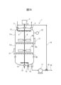
- FIG. 1 is a vertical cross-sectional view (perspective side view) of a vertical multi-stage stirring system according to one embodiment.
- FIG. 2 is a vertical cross-sectional view (perspective side view) of a stirring device in which the attrition medium is removed from the vertical multi-stage stirring system of the embodiment of FIG. 1 .
- 1 is a top view including a partial cross-sectional view of an impeller according to one embodiment. The area Z surrounded by a dotted line shows a C-C' cross-sectional view of the blade portion of the impeller.
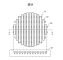
- FIG. 1 is a top view including a partial cross-sectional view of a wedge wire screen according to one embodiment, in which the area X surrounded by a dotted line indicates the A-A' cross-sectional view of the wedge wire screen.
- FIG. 1 is a top view including a partial cross-sectional view of a wedge wire screen according to an embodiment of the present invention, in which the area Y surrounded by a dotted line shows a cross-sectional view B-B' of the wedge wire screen.
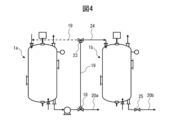
- FIG. 1 is a schematic diagram of an apparatus including two vertical multi-stage stirring systems connected in series.
- FIG. 1 is a flow diagram illustrating an overview of a CO2 fixation method.
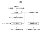
- FIG. 1 is a flow diagram illustrating an overview of a method for recovering valuable metals in combination with a CO2 fixation method.
- FIG. 2 is a flow diagram outlining the HPAL process.
- Attrition means thinning the particle surface without significantly changing the particle size of the alkaline earth metal-containing particles, unlike grinding. Without being bound by any theory, it is believed that by contacting the attrition medium with the alkaline earth metal-containing particles during stirring, the surface layer (alkaline earth metal depleted layer) of the alkaline earth metal-containing particles, in which the alkaline earth metal has been extracted and the alkaline earth metal concentration has been reduced, is thinly peeled off to expose fresh particle surfaces with a higher alkaline earth metal content, and/or the alkaline earth metal salts, e.g., alkaline earth metal carbonates, precipitated on the surfaces of the alkaline earth metal-containing particles are scraped off to re-expose the surfaces of the alkaline earth metal-containing particles.
- alkaline earth metal salts e.g., alkaline earth metal carbonates
- Fine particles may be generated by attrition of the alkaline earth metal-containing particles during stirring, but the average particle size of the alkaline earth metal-containing particles does not change significantly.
- the vertical multi-stage stirring system includes a stirring device including a stirring vessel containing a plurality of stirring chambers arranged along a vertical direction, a slurry supply port provided at an upper part of the stirring vessel, a slurry discharge port provided at a lower part of the stirring vessel, a shaft extending along a vertical direction through the center of the plurality of stirring chambers, a stirrer motor attached to one end of the shaft, a plurality of stirring blades attached to the shaft, at least one of the plurality of stirring blades being located inside each of the plurality of stirring chambers, and a plurality of sieve plates arranged at the lower part of each of the plurality of stirring chambers.
- the reaction between CO2 gas and the alkaline earth metal-containing particles at room temperature and normal pressure includes dissolving CO2 gas in the liquid phase of the slurry containing the alkaline earth metal-containing particles to form HCO3- ions , penetrating the grain boundaries of the ultramagnesium iron mineral FeMgSiO2 , reacting with the alkaline earth metal to form a soluble salt, and dissolving the soluble salt in the liquid phase.
- the vertical multi-stage stirring system of the present disclosure includes a plurality of stirring chambers arranged along the vertical direction, so that the contact opportunity between the CO 2 gas and the liquid phase and the slurry containing alkaline earth metal-containing particles can be ensured for each stirring chamber (each stage).
- the residence time of the CO 2 gas in the stirring vessel can be increased, and the slurry and the CO 2 gas flow countercurrently, so that the slurry with a reduced alkaline earth metal concentration can be contacted with a high concentration (fresh) CO 2 gas. Therefore, the CO 2 gas can be efficiently dissolved in the liquid phase, and the contact opportunity between the HCO 3 - ions and the alkaline earth metal can be increased, and as a result, the extraction efficiency of the alkaline earth metal into the liquid phase can be improved.
- FIG. 1 shows a vertical cross-sectional view (perspective side view) of one embodiment of a vertical multi-stage stirring system 1.
- FIG. 1A shows a vertical cross-sectional view (perspective side view) of a stirring device in which the abrasion medium 7 is removed from the vertical multi-stage stirring system 1 of the embodiment of FIG. 1.
- the stirring device constituting the vertical multi-stage stirring system 1 includes a stirring vessel 12, a slurry supply port 2 provided in the upper part of the stirring vessel 12, and a slurry discharge port 16 provided in the lower part of the stirring vessel 12.
- an exhaust gas outlet 4 is provided in the upper part of the stirring vessel 12.
- the exhaust gas outlet 4 may be always open so that the internal pressure of the stirring vessel 12 is maintained at atmospheric pressure, or may be opened and closed during operation so that CO2 gas inside the stirring vessel 12 is discharged to the outside when the internal pressure of the stirring vessel 12 excessively increases.
- the slurry supply port 2 is connected to a slurry distribution nozzle 5.
- the slurry distribution nozzle 5 the slurry can be dispersed and supplied from the upper inside of the stirring vessel 12, thereby improving the reaction efficiency between the alkaline earth metal-containing particles and the CO2 gas, and the attrition efficiency of the alkaline earth metal-containing particles in the slurry.
- the slurry outlet 16 may be connected to a slurry pump 17 to facilitate the discharge or circulation of the slurry.
- the outlet of the slurry pump 17 is connected to a slurry circulation line 19 and a slurry discharge line 20 via a three-way valve 18.
- the slurry pump 17 may or may not be present and the three-way valve 18 is replaced with a two-way valve.
- a gas supply port 13 is provided at the bottom of the stirring vessel 12.
- the gas supply port 13 may be provided at any position of the stirring vessel 12 as long as CO2 gas can be introduced into the inside of the stirring vessel 12, and multiple gas supply ports 13 may be provided. It is preferable to provide the gas supply port 13 at the bottom of the stirring vessel 12.
- the CO2 gas moving upward and the slurry supplied from above and descending can be countercurrently contacted. This allows the CO2 gas to be more efficiently absorbed into the liquid phase of the slurry, thereby increasing the extraction efficiency of the alkaline earth metal.
- the stirring vessel 12 further includes a gas dispersion nozzle 14 communicating with the gas supply port 13.
- the gas dispersion nozzle 14 By using the gas dispersion nozzle 14, the CO2 gas can be dispersed and supplied into the inside of the stirring vessel 12, thereby increasing the reaction efficiency between the alkaline earth metal-containing particles and the CO2 gas.
- the opening of the gas dispersion nozzle 14 is preferably facing downward. By facing downward, clogging of the opening of the gas dispersion nozzle 14 due to accumulation of slurry can be suppressed or prevented.
- the stirring vessel 12 contains multiple stirring chambers 11a, 11b arranged along the vertical direction.
- the stirring vessel 12 is depicted as containing two stirring chambers 11a, 11b, but the stirring vessel 12 may contain three, four, five or more stirring chambers.
- the stirring device includes a shaft 8 extending vertically through the center of the multiple stirring chambers 11a, 11b of the stirring vessel 12, an agitator motor 3 attached to one end of the shaft 8, and multiple stirring blades 9a, 9b attached to the shaft 8.
- the stirring blade 9a is located inside the stirring chamber 11a
- the stirring blade 9b is located inside the stirring chamber 11b.
- the shaft 8 is supported by bearings 6, 15 attached to the upper center and lower center of the stirring vessel 12. The bearings 6, 15 may maintain an airtight state between the shaft 8 and the stirring vessel 12.
- the agitator motor 3 is attached to the upper end of the shaft 8, but it may also be attached to the lower end of the shaft 8.
- the multiple impellers 9a, 9b may be, for example, paddle-type impellers, propeller-type impellers, or disk-type impellers.
- the multiple impellers 9a, 9b are preferably paddle-type.
- the paddle-type impellers can move the abrasion medium 7 at a low speed. This can suppress damage or wear of the abrasion medium 7, and increase the chance of contacting the alkaline earth metal-containing particles in the slurry with the abrasion medium 7 while allowing them to settle in the slurry without being excessively suspended, thereby more effectively abrading the alkaline earth metal-containing particles.
- wear of the impellers 9a, 9b caused by the abrasion medium 7 can also be suppressed.
- the multiple agitator blades 9a, 9b are preferably inclined so that the rear side is lower in the direction of rotation of the shaft 8.
- the slurry caught in the agitator blades 9a, 9b moves toward the sieve plates 10a, 10b while the agitator blades 9a, 9b are rotating.
- This increases the amount of slurry sent between the attrition medium 7 and the sieve plates 10a, 10b, suppresses the suspension of alkaline earth metal-containing particles in the slurry, and promotes attrition of the alkaline earth metal-containing particles by the attrition medium 7.
- the agitator impeller 9 has four blade portions 91 and a cylindrical sleeve-shaped boss portion 92 that connects the blade portions 91 and has a hole for receiving the shaft 8.
- the blade portions 91 are attached to the boss portion 92 by welding.
- the shaft 8 is inserted into the boss portion 92, and the boss portion 92 and the shaft 8 are fixed by pins and screws or by welding.
- the agitator impeller 9 shown in FIG. 2 is a paddle-type agitator impeller, specifically, an inclined paddle-type agitator impeller.
- the area Z surrounded by a dotted line shows a C-C' cross-section of the blade portion 91 of the agitator impeller 9.
- the blade portion 91 is inclined at an angle ⁇ with respect to the horizontal plane h so that the rear of the blade portion 91 is lower in the direction of rotation of the shaft 8, i.e., the direction of rotation R of the agitator impeller.
- the angle ⁇ is preferably 45 degrees to 90 degrees, and more preferably 60 degrees to 75 degrees.
- a plurality of sieve plates 10a, 10b are arranged inside the stirring vessel 12.
- the sieve plate 10a is arranged at the bottom of the stirring chamber 11a
- the sieve plate 10b is arranged at the bottom of the stirring chamber 11b.
- the sieve plate 10a defines the stirring chamber 11a together with the top and side wall of the stirring vessel 12
- the sieve plate 10b defines the stirring chamber 11b together with the sieve plate 10a and the side wall of the stirring vessel 12.
- a wedge wire screen, a punched metal, a mesh screen, or a sintered screen can be used as the sieve plate.
- the mesh size of the sieve plates 10a and 10b is set so that the attrition medium 7 does not pass through, but particles smaller than a certain particle size and CO2 gas pass through, and decreases from top to bottom. That is, the mesh size of the sieve plate 10a is larger than that of the sieve plate 10b located below it. This ensures the residence time of the slurry in each of the stirring chambers 11a and 11b, and allows the attrition of the alkaline earth metal-containing particles and the extraction of the alkaline earth metal into the liquid phase to be effectively performed in both of the stirring chambers 11a and 11b.
- the mesh size of the sieve plates 10a, 10b can be appropriately determined depending on the average particle size of the attrition medium 7, the average particle size of the alkaline earth metal-containing particles in the slurry, the number of stirring chambers (number of stages), etc.
- the mesh size of the sieve plates 10a, 10b can be, for example, 100 ⁇ m (150 mesh) to 250 ⁇ m (60 mesh), preferably 132 ⁇ m (120 mesh) to 250 ⁇ m (60 mesh), and more preferably 150 ⁇ m (100 mesh) to 180 ⁇ m (83 mesh).
- the mesh size of sieve plates 10a and 10b is preferably 80% to 95% of the mesh size ( ⁇ m) of the next higher sieve plate in question, and more preferably 80% to 90%.
- the mesh size of sieve plate 10a is 180 ⁇ m
- the sieve plates 10a, 10b are preferably wedge wire screens. Wedge wire screens are also known under the trade name Johnson Screens (Johnson Screens Japan, Inc.).
- FIG. 3A and 3B show top views including a partial cross-sectional view of a wedge wire screen according to one embodiment.
- the wedge wire screen (sieve plate) 10 includes a plurality of wedges 101, each of which is made of stainless steel or the like and has an elongated triangular prism shape, arranged in parallel with the tops of the wedges 101 facing downward and the bottoms of the wedges 101 facing upward.
- the wedges 101 are fixed to a support 102 arranged below the wedges 101 so as to contact their tops.
- the area X enclosed by a dotted line in FIG. 3A shows the A-A' cross-sectional view of the wedge wire screen 10. As shown in FIG.
- a plurality of wedges 101 having triangular cross sections are arranged in parallel, and a plurality of elongated parallel gaps are formed between the top surfaces (triangular bases) of the wedges 101.
- the area Y enclosed by a dotted line in FIG. 3B shows the B-B' cross-sectional view of the wedge wire screen 10.
- the wedges 101 are fixed in contact with the support 102 at their lower parts (triangular tops).
- the stirring vessel 12 may be provided with an inspection port 21 that allows observation of the inside of the stirring vessel 12 or allows internal work to be performed on the stirring vessel 12.
- the inspection port 21 may be provided on the side wall of the stirring vessel 12, and is preferably provided at a position corresponding to each of the stirring chambers 11a, 11b.
- the inspection port 21 allows inspection, cleaning, replacement, etc. of the abrasion medium 7, the stirring blades 9a, 9b, or the sieve plates 10a, 10b.
- the stirring vessel 12 may be provided with a pressure gauge 22 for measuring the internal pressure of the stirring vessel 12.
- the pressure gauge 22 is preferably attached to the upper part of the stirring vessel 12.
- the internal pressure of the stirring device 12 can be reduced by adjusting the supply rate of the slurry or CO 2 gas, discharging CO 2 gas from the exhaust gas outlet 4, or discharging the slurry by operating the slurry pump 17, as necessary.
- a warning device (not shown) may be activated, or the system may be automatically stopped.
- the vertical multi-stage stirring system 1 includes an abrasion medium 7 arranged separately from the multiple agitation blades 9a, 9b inside each of the multiple agitation chambers 11a, 11b of the stirring device.
- the abrasion medium 7 can be moved irregularly by the agitation blades 9a, 9b, thereby increasing the abrasion efficiency of the alkaline earth metal-containing particles.
- the abrasion medium 7 is not particularly limited as long as it has the ability to abrade the surface of the alkaline earth metal-containing particles.
- Examples of the shape of the abrasion medium 7 include beads, balls, rods, and pebbles. It is preferable that the abrasion medium 7 be spherical, such as beads or balls, because it can effectively abrade the alkaline earth metal-containing particles while suppressing crushing of the alkaline earth metal-containing particles.
- the average particle size of the abrasion medium 7 is preferably 0.3 mm to 20 mm, more preferably 0.5 mm to 15 mm, and even more preferably 1 mm to 12 mm. By setting the average particle size of the abrasion medium 7 within the above range, the abrasion efficiency of the alkaline earth metal-containing particles can be increased.
- the average particle size of the abrasion medium 7 is the sieve diameter determined in accordance with JIS Z 8801-1-1:2019.
- the Mohs hardness of the attrition medium 7 is not particularly limited as long as it can attrit the surface of the alkaline earth metal-containing particles. In one embodiment, the Mohs hardness of the attrition medium 7 is 3 or more. In order to suppress the crushing of the alkaline earth metal-containing particles and facilitate solid-liquid separation in the CO2 fixation described below, the Mohs hardness of the attrition medium 7 is preferably 9 or less. For example, when the alkaline earth metal-containing particles are serpentine (Mohs hardness 3 to 4), the Mohs hardness of the attrition medium 7 is preferably 3 or more, or 4 or more and 9 or less.
- Examples of materials for the abrasion medium 7 include alumina, silicon nitride, zirconia, tungsten, tungsten carbide, and stainless steel. It is preferable that the abrasion medium 7 contains alumina.
- FIG. 4 shows a schematic diagram of an apparatus including two vertical multi-stage stirring systems 1a and 1b connected in series.
- the vertical multi-stage stirring systems 1a and 1b are connected in series via a three-way valve 18, a part of the slurry supply line 19, a three-way valve 23, and a slurry supply line 24.
- the slurry discharged from the slurry discharge port of the vertical multi-stage stirring system 1a is sent to the three-way valve 18 by the slurry pump.
- the three-way valve 18 is open to the slurry pump and the slurry discharge line 20a and closed to the slurry circulation line 19, the slurry is discharged to the outside and used in the next process.
- the three-way valve 18 When the three-way valve 18 is open to the slurry pump and the slurry circulation line 19 and closed to the slurry discharge line 20a, and the three-way valve 23 is open to the slurry circulation line 19 (solid line and dotted line) and closed to the slurry supply line 24, the slurry is supplied again into the stirring vessel from the slurry supply port of the vertical multi-stage stirring system 1a.
- the slurry is supplied from the slurry supply port of the vertical multi-stage stirring system 1b to the stirring vessel of the vertical multi-stage stirring system 1b.
- the treated slurry can be transferred to the vertical multi-stage stirring system 1b, and new slurry can be treated in the vertical multi-stage stirring system 1a.
- the slurry discharge port of the most downstream vertical multi-stage mixing system 1b may be connected to a slurry discharge line 20b via a two-way valve 25 and, if necessary, a slurry pump (not shown).
- FIG. 5 An outline of the CO2 fixation method is shown in a flow diagram in Figure 5.
- the parts enclosed in squares indicate steps or devices.
- an alkaline earth metal-containing raw material is added as an optional step.
- the alkaline earth metal-containing particles are obtained by pre-treating the alkaline earth metal-containing particles.
- An aqueous medium is added to the alkaline earth metal-containing particles to obtain a slurry.
- the slurry is mixed with CO2 gas while being stirred,
- the alkaline earth metal ions in the alkaline earth metal-containing particles are extracted into a liquid phase.
- the vertical multi-stage stirring system having a gas supply port provided at the bottom of the stirring vessel; (2) supplying a slurry containing alkaline earth metal-containing particles and an aqueous medium to a slurry supply port; (3) supplying CO2 gas to the gas supply port; (4) Stirring and mixing the slurry and CO2 gas in one of the multiple stirring chambers to extract alkaline earth metal ions in the alkaline earth metal-containing particles into a liquid phase, and moving the alkaline earth metal-containing particles to another stirring chamber among the multiple stirring chambers located below the one stirring chamber through a sieve plate arranged at the bottom of the one stirring chamber; (5) removing the mixture in which the alkaline earth metal ions have been extracted into the liquid phase from a slurry outlet, and then subjecting the mixture to solid-liquid separation to obtain a liquid phase containing the alkaline earth metal ions and a solid phase containing the extraction residue; and (6) precipitating an alkaline earth metal carbonate
- alkaline earth metal-containing particles are not particularly limited as long as they contain an alkaline earth metal.
- "alkaline earth metal” means an element of Group 2 of the periodic table.
- the alkaline earth metal is preferably at least one selected from the group consisting of Mg, Ca, Sr, and Ba, more preferably at least one selected from the group consisting of Mg and Ca, and even more preferably contains Mg.
- alkaline earth metal-containing particles examples include particles of Mg-containing ore, Mg-containing slag, Ca-containing slag, coal ash, clinker kiln dust, waste concrete, concrete sludge, and cement.
- the alkaline earth metal-containing particles are particles of Mg-containing ore.
- Mg-containing ores include limonite (MgO content 0.5 to 5% by mass), smectite (MgO content 5 to 15% by mass), and saprolite (MgO content 15 to 35% by mass).
- the Mg-containing ore preferably contains ultramafic rock, and preferably contains at least one mineral selected from the group consisting of olivine (composition formula: (Mg, Fe) SiO 4 ) and serpentine (composition formula: (Mg, Fe) 3 Si 2 O 5 (OH) 4 ). Since olivine and serpentine are high Mg-containing minerals, the amount of alkaline earth metal-containing particles required for CO 2 fixation can be reduced.
- the alkaline earth metal-containing particles may be formed by pre-treating an alkaline earth metal-containing raw material.
- the alkaline earth metal-containing raw material may be a material described for the alkaline earth metal-containing particles, such as Mg-containing ore, Mg-containing slag, Ca-containing slag, coal ash, clinker kiln dust, waste concrete, concrete sludge, or cement.
- Pretreatments include, for example, grinding and heat treatment.
- the grinding can be carried out using a known grinding device.
- the grinding can reduce the average particle size of the alkaline earth metal-containing particles to increase their surface area, or expose the active surfaces of the alkaline earth metal-containing particles. This can increase the extraction efficiency of the alkaline earth metal.
- the grinding can be carried out under conditions such that the alkaline earth metal-containing particles have a suitable average particle size, which will be described later. If necessary, the alkaline earth metal may be classified using a sieve or the like after grinding.
- the heat treatment can be carried out using a known heat treatment device.
- the heat treatment temperature can be, for example, 500°C to 800°C, and the heat treatment time can be 1 minute to 2 hours.
- the alkaline earth metal-containing particles are heat-treated.
- the crystal water in the alkaline earth metal-containing raw material can be removed, and the alkaline earth metal in the alkaline earth metal-containing particles can be activated to a form that is easily dissolved into the liquid phase, thereby increasing the extraction efficiency of the alkaline earth metal.
- the smaller the particle size the easier it is for heat to be transmitted to the inside of the particle, and the greater the efficiency of the heat treatment, so it is preferable to carry out the heat treatment after the above-mentioned crushing.
- pretreatment equipment equipment used for pretreatment, such as grinding equipment and heat treatment equipment, is collectively referred to as pretreatment equipment.
- the average particle size of the alkaline earth metal-containing particles can be appropriately determined according to the volume of the stirring vessel 12, the output of the stirrer motor 3, the type of the stirring blades 9a and 9b, the size of the attrition medium 7, and the like, and is not particularly limited.
- the average particle size of the alkaline earth metal-containing particles can be, for example, within the range of 10 ⁇ m to 500 ⁇ m, 20 ⁇ m to 450 ⁇ m, or 100 ⁇ m to 400 ⁇ m. By setting the average particle size of the alkaline earth metal-containing particles to 10 ⁇ m or more, solid-liquid separation in CO 2 fixation can be facilitated.
- the average particle size of the alkaline earth metal-containing particles is defined as the 50% cumulative volume average diameter D 50 by the laser diffraction scattering method.
- the aqueous medium has the ability to dissolve CO2 gas, and is generally water.
- the aqueous medium may contain water-soluble organic solvents such as alcohols and esters as necessary. Salts such as sodium chloride, potassium chloride, ammonium chloride, sodium sulfate, magnesium sulfate, ammonium hydrogen sulfate, and sodium hydrogen carbonate may be dissolved in the aqueous medium.
- the content of water in the aqueous medium is preferably 70% by mass or more, more preferably 80% by mass or more, and even more preferably 90% by mass or more.
- the slurry can be prepared by adding alkaline earth metal-containing particles to an aqueous medium and mixing them.
- the slurry supplied as a raw material contains alkaline earth metal-containing particles in an amount of 0.5% by mass to 50% by mass.
- the lower the content of alkaline earth metal-containing particles in the slurry the greater the ratio of the liquid phase to the solid phase (alkaline earth metal-containing particles), so the extraction efficiency of the alkaline earth metal increases, but a larger facility is required for extraction.
- the higher the content of alkaline earth metal-containing particles in the slurry the smaller the facility required for extraction, but the lower the extraction efficiency of the alkaline earth metal.
- the slurry does not contain any acid added from outside other than CO2 gas.
- the slurry By supplying the slurry to the slurry supply port 2, the slurry is supplied from the upper part inside the stirring vessel 12.
- the slurry may be supplied into the stirring vessel 12 through the slurry dispersion nozzle 5.
- the supply rate of the slurry can be appropriately determined in consideration of parameters such as the volume of the stirring vessel 12, the spatial volume of the stirring chambers 11a and 11b, the number of stirring chambers (number of stages), the content of alkaline earth metal-containing particles in the slurry, the average particle size of the alkaline earth metal-containing particles, and the supply rate of CO2 gas.
- the slurry moves downward inside the stirring vessel 12.
- CO2 gas By supplying CO2 gas to the gas supply port 13, CO2 gas is supplied from the lower inside of the stirring vessel 12.
- the CO2 gas may be supplied into the stirring vessel 12 through a gas dispersion nozzle 14. Since the CO2 gas moves upward inside the stirring vessel 12, it comes into countercurrent contact with the descending slurry. This allows the CO2 gas to be more efficiently absorbed into the liquid phase of the slurry, thereby increasing the extraction efficiency of the alkaline earth metal.
- the CO2 gas supply source may be, for example, at least one selected from the group consisting of a coal power plant, an oil power plant, a natural gas power plant, a biomass power plant, a coal boiler, a smelting facility, a neutralization facility, and a roasting facility. Since a coal power plant has a particularly large amount of CO2 gas emissions, the CO2 gas emissions can be effectively reduced by using the CO2 fixation method described later.
- the roasting facility as the CO2 gas supply source may be one used in the roasting process described later.
- the supply rate of CO2 gas can be optimized in consideration of design factors such as the saturation solubility of CO2 , extraction efficiency, power required for supply, superficial velocity, pressure loss, gas-liquid flow rate ratio, and the height of the slurry surface in the stirring chamber. It is preferable to determine the supply rate of CO2 gas so that the amount of CO2 dissolved in the liquid phase of the slurry is saturated at the temperature and pressure during stirring.
- the slurry and CO2 gas are stirred and mixed in one of the stirring chambers 11a and 11b, and the alkaline earth metal ions in the alkaline earth metal-containing particles are extracted into the liquid phase.
- the stirring and mixing causes the CO2 gas to dissolve in the liquid phase of the slurry, lowering the pH of the liquid phase. This promotes the dissolution and ionization of the alkaline earth metal in the alkaline earth metal-containing particles into the liquid phase.
- the alkaline earth metal-containing particles in the slurry are abraded by the abrasion medium 7 during stirring and mixing, becoming smaller in particle size, and move through the sieve plate 10a arranged at the bottom of the stirring chamber 11a to another stirring chamber 11b located below the stirring chamber 11a.
- the liquid phase in the slurry also moves through the sieve plate 10a to another stirring chamber 11b located below, accompanied by or independent of the alkaline earth metal-containing particles.
- a slurry containing alkaline earth metal-containing particles with a reduced particle size is supplied to the stirring chamber 11b, and this slurry is also agitated and mixed with the CO 2 gas rising from the bottom of the stirring vessel 12.
- a slurry containing alkaline earth metal-containing particles with a smaller particle size is supplied to another stirring chamber located below and is agitated and mixed with CO 2 gas.
- a slurry containing alkaline earth metal-containing particles with a smaller particle size is supplied to another stirring chamber located below and is agitated and mixed with CO 2 gas.
- contact opportunities between the CO2 gas and the alkaline earth metal-containing particles are ensured in each stirring chamber (each stage), and by supplying CO2 gas from the bottom of the stirring vessel, the residence time of the CO2 gas in the stirring vessel is increased, thereby improving the extraction efficiency of the alkaline earth metal into the liquid phase.
- the amount of the attrition medium 7 used is not particularly limited, but taking into consideration the efficiency of alkaline earth metal extraction and the power consumption related to stirring, it is preferable to adjust it so that a sufficient amount of alkaline earth metal-containing particles is present in the volume portion where the attrition medium 7 is present during stirring.
- the amount of the attrition medium 7 used can be, for example, equal to or greater than the height of the stirring blades 9a, 9b arranged inside the stirring chambers 11a, 11b.
- the rotation speed of the agitator blades 9a, 9b can be, for example, 10 rpm to 500 rpm, or 20 rpm to 200 rpm.
- the rotation speed of the agitator blades 9a, 9b can be, for example, 10 rpm to 500 rpm, or 20 rpm to 200 rpm.
- the stirring and mixing is performed at a temperature of the aqueous medium above the freezing point and below 50°C, preferably 0°C to 30°C. If the slurry contains a soluble substance, such as sodium chloride, the freezing point of the aqueous medium may drop below 0°C.
- the stirring and mixing can be performed uniformly and an excessive increase in power consumption associated with the stirring and mixing can be prevented.
- the stirring and mixing is performed at a temperature of 50°C or less, the CO2 concentration dissolved in the aqueous medium can be set to a desired range.
- the stirring is performed at ambient temperature without heating.
- stirring and mixing is performed under a pressure atmosphere of atmospheric pressure or more and 10 MPaG (gauge pressure) or less, preferably 1.0 MPaG (gauge pressure) or less, more preferably 0.5 MPaG (gauge pressure) or less.
- the higher the CO2 pressure the more CO2 dissolves in the liquid phase of the slurry, and therefore the higher the extraction efficiency of the alkaline earth metal.
- the alkaline earth metal ions in the alkaline earth metal-containing particles can be efficiently extracted into the liquid phase. By using low pressure conditions, the power consumption related to the extraction of alkaline earth metal ions can be effectively reduced.
- stirring is performed under an atmospheric pressure atmosphere.
- the residence time of the slurry in the mixing chambers 11a and 11b is not particularly limited, but can be 15 to 60 minutes for each mixing chamber.
- the alkaline earth metal ions extracted into the liquid phase may be present in the form of alkaline earth metal hydroxide, alkaline earth metal silicate, or alkaline earth metal silicate double salt.
- alkaline earth metal hydroxides include Mg(OH) 2 and Ca(OH) 2 , which are generated by hydration of MgO or CaO .
- alkaline earth metal silicate include Mg2SiO4 (magnesium silicate ) and Ca2SiO4 .
- alkaline earth metal silicate double salts include, for example, silicates of alkaline earth metals and alkali metals, Mn, Fe, Co, Ni, Cu, Zn, or Al, or two or more of these.
- a representative alkaline earth metal silicate double salt is (Mg,Fe) SiO4 (mafic silicate).
- the alkaline earth metal ions are present in the form of alkaline earth metal silicates or alkaline earth metal double silicates, which are converted to alkaline earth metal carbonates during CO2 fixation.
- the mixture in which the alkaline earth metal ions have been extracted into the liquid phase is taken out from the slurry outlet 16 and subjected to solid-liquid separation.
- Methods for solid-liquid separation include, for example, filtration, pressing, sedimentation, and centrifugation.
- Solid-liquid separation can be carried out using a general solid-liquid separation device.
- solid-liquid separation devices include vacuum separation devices, centrifugal separators, multiple disk separators, belt presses, screw presses, roller presses, rotary drum screens, belt screens, vibrating screens, thickeners, ceramic filters, pleated filters, and multiple plate wave filters.
- the alkaline earth metal carbonate is precipitated from the liquid phase, and CO2 is fixed in the alkaline earth metal carbonate.
- the solubility of the alkaline earth metal carbonate decreases with increasing temperature. Therefore, the precipitation of the alkaline earth metal carbonate can be promoted by increasing the temperature of the liquid phase.
- the precipitation of the alkaline earth metal carbonate can also be performed by bubbling the liquid phase with air or by placing the liquid phase under reduced pressure.
- the precipitation device may be a tank equipped with a temperature control mechanism.
- the precipitation device may further include a solid-liquid separation device for separating the precipitated alkaline earth metal salt.
- the temperature of the liquid phase during precipitation can be, for example, 20°C to 80°C.
- the precipitation time can be, for example, 10 minutes to 100 hours.
- CO2 gas was supplied to the gas supply port 13 provided at the bottom of the stirring vessel 12, but CO2 gas can also be supplied to the slurry supply port 2 accompanied by the slurry, or can be supplied to one or more gas supply ports (not shown) provided other than at the bottom of the stirring vessel 12.
- a method for fixing CO 2 and recovering valuable metals includes pretreating an alkaline earth metal-containing raw material containing valuable metals and alkaline earth metals to obtain alkaline earth metal-containing particles and a valuable metal-containing residue; carrying out the CO 2 fixation method using the alkaline earth metal-containing particles; and recovering a product, intermediate, or both containing valuable metals from the valuable metal-containing residue.
- Figure 6 shows a flow diagram of an outline of a valuable metal recovery method combined with a CO2 fixation method.
- alkaline earth metal-containing particles and valuable metal-containing residue are produced from the starting material, and these are each supplied to a different subsequent step.
- the alkaline earth metal-containing particles are used for CO2 fixation to produce alkaline earth metal carbonate.
- the extraction residue may also be used as a valuable metal-containing residue.
- alkaline earth metal-containing particles and valuable metal-containing residues are obtained from the starting material.
- the starting materials include valuable metals and alkaline earth metals.
- the form of the starting materials is not particularly limited, and may be, for example, ores, solutions, slurry, powders, lumps, or molded bodies.
- the powders and lumps can be obtained, for example, by crushing the ores, or by drying and crushing the solutions or slurry.
- the powders or lumps may be dried by evaporating and removing the free water.
- the molded bodies can be obtained, for example, by tableting the ores, powders, or lumps.
- the molded bodies may be mixed with agents used in pretreatment, such as fuel for roasting.
- the valuable metal is not particularly limited, but is, for example, at least one selected from the group consisting of Ni, Co, Fe, Cu, and platinum group metals.
- platinum group metals PGM is a general term for ruthenium, rhodium, palladium, osmium, iridium, and platinum, and means any one of these or a combination of two or more of them.
- the valuable metal may include gold, silver, or a combination thereof.
- the starting material is an ore containing the above valuable metal.
- examples of such ores include nickel oxide ore, nickel sulfide ore, cobalt ore, iron ore, copper ore, platinum ore, and metal concentrates obtained by flotation of any one or more of these ores.
- the ore is preferably nickel oxide ore.
- nickel oxide ores include limonite (MgO content: 0.5 to 5% by mass), smectite (MgO content: 5 to 15% by mass), and saprolite (MgO content: 15 to 35% by mass).
- the alkaline earth metal preferably contains Mg.
- the starting material comprises ultramafic rock, which preferably comprises at least one mineral selected from the group consisting of olivine (composition formula: (Mg, Fe)SiO 4 ) and serpentine (composition formula: (Mg, Fe) 3 Si 2 O 5 (OH) 4 ).
- Pretreatment includes processes that change the chemical composition or chemical properties of the starting material so that it can be separated into alkaline earth metal-containing particles and valuable metal-containing residue. Examples of such processes include oxidizing roasting, sulfating roasting, and salt conversion/solid-liquid separation.
- the oxidative roasting can be carried out, for example, using a roasting furnace.
- An exemplary oxidative roasting method includes the following steps: Using fuel such as natural gas, petroleum, coal, sulfur, or pyrite (FeS 2 ), oxygen partial pressure is increased by supplying oxygen, air, or the like, and the starting material is heated to about 500°C to 700°C for oxidative decomposition.
- the alkaline earth metal is converted to an alkaline earth metal oxide and recovered as alkaline earth metal-containing particles.
- high Mg-containing minerals such as olivine and serpentine are thermally decomposed into MgO and SiO 2 by oxidative roasting.
- This pyrolysis product may also contain Fe 2 O 3 , Mg 2 SiO 4 , (Mg,Fe)SiO 4 , or a combination thereof. Valuable metals are also recovered in the form of oxides as valuable metal-containing residues.
- Sulfation roasting can be carried out, for example, using a rotary kiln, a fluidized bed heating furnace, or an electric furnace.
- An exemplary sulfation roasting includes the following steps: Sulfur or a sulfur compound such as sodium sulfide, calcium sulfide, pyrrhotite, or pyrite is mixed with the starting material as a reduction promoter, and the mixture is heated to a reduction range of the valuable metal, for example, about 400°C to 680°C for Ni, to selectively sulfate the valuable metal.
- metal sulfides are formed using H 2 S gas or the like, or valuable metal hydroxides are formed by adjusting the pH using an alkali such as Ca(OH) 2 or NaOH, and then the alkaline earth metal-containing particles and valuable metal-containing residue can be separated by solid-liquid separation.
- Another exemplary sulfation roasting includes adding concentrated sulfuric acid to the starting material, and then performing oxidative roasting to sulfate the valuable metal.
- the salt conversion and solid-liquid separation can be carried out, for example, using hot water or an acidic aqueous solution such as sulfuric acid, hydrochloric acid, or nitric acid.
- An exemplary method includes the following steps: The starting material is placed in a container, and hot water or an acidic aqueous solution such as sulfuric acid, hydrochloric acid, or nitric acid is added to dissolve the alkaline earth metals and valuable metals in the form of their salts. After the addition of the hot water or acidic aqueous solution, an oxidizing agent such as H 2 O 2 or KMnO 4 may be added and stirred to promote dissolution of the alkaline earth metals or valuable metals.
- an oxidizing agent such as H 2 O 2 or KMnO 4 may be added and stirred to promote dissolution of the alkaline earth metals or valuable metals.
- the dissolved alkaline earth metals and valuable metals can be separated into alkaline earth metal-containing particles and valuable metal-containing residue by solid - liquid separation after forming metal sulfides using H 2 S gas or the like, or forming valuable metal hydroxides by adjusting the pH using an alkali such as Ca(OH) 2 or NaOH.
- Pretreatment preferably includes oxidative roasting.
- the mixture of alkaline earth metal oxides and valuable metal oxides obtained by oxidative roasting the starting material can be easily separated by a separation process such as specific gravity separation.
- pretreatment may include exhaust gas treatment of sulfur dioxide.
- a general sulfuric acid plant can be used as an exhaust gas treatment facility for sulfur dioxide.
- the concentrated sulfuric acid generated by the exhaust gas treatment of sulfur dioxide can be effectively used as a product or in valuable metal recovery by the method disclosed herein, particularly valuable metal recovery using the high pressure acid leaching (HPAL) method.
- HPAL high pressure acid leaching
- the pretreatment may further include a separation step.
- separation methods include specific gravity separation, particle size separation, and chemical composition separation.
- Specific gravity separation is a method of separating particles that have different specific gravities depending on their chemical composition, by utilizing the difference in specific gravity. Specific gravity separation can be performed, for example, using a fluidized specific gravity separation device used in coal preparation technology.
- Particle size separation is a method of separating particles that have different concentrations of valuable metals depending on their size, or that have valuable metals in minerals in the form of fine particles, by utilizing the difference in particle size. Particle size separation can be performed, for example, using a sieve or a centrifuge.
- Chemical composition separation is a method of separating particles that contain special metals such as uranium by analyzing them online using infrared rays and selectively blowing away only the particles with an air gun.
- the pretreatment preferably includes separating alkaline earth metal-containing particles and valuable metal-containing residue by gravity separation.
- the gravity separation device for example, when the specific gravity is set to 4, substances with low specific gravity such as MgO and SiO2 can be separated as alkaline earth metal-containing particles, and substances with high specific gravity containing valuable metals such as NiO, CoO, and Fe2O3 can be separated as valuable metal-containing residue.
- the alkaline earth metal-containing particles obtained by the pretreatment may contain, in addition to the alkaline earth metal, other elements such as silicon, aluminum, or two or more of these.
- the alkaline earth metal and other elements may be present in the alkaline earth metal-containing particles in the form of oxides, sulfates , silicates, or combinations thereof.
- the alkaline earth metal-containing particles include MgO, SiO2 , and Mg2SiO4 .
- the valuable metal-containing residue may contain, in addition to the valuable metal, for example, silicon, aluminum, or two or more of these elements.
- the valuable metal may be present in the valuable metal-containing residue in the form of an oxide, chloride, sulfide, or a combination thereof.
- the valuable metal-containing residue contains at least one selected from the group consisting of NiO, CoO, and Fe2O3 .
- the CO2 fixation using alkaline earth metal-containing particles is as described in the CO2 fixation method.
- the heat generated in the pretreatment for example, the roasting process, can be reused as a heat source for heating the liquid phase.
- the CO2 emission associated with heating can be reduced or eliminated.
- the alkaline earth metal carbonate produced can be used as an alkaline earth metal carbonate product, or when valuable metal recovery in the disclosed method is performed by high pressure acid leaching (HPAL), it can be used as a neutralizing agent for primary neutralization, final neutralization, tailings dam pH adjustment, etc., which are subsequent steps in the HPAL process.
- HPAL high pressure acid leaching
- MgCO3 generated by CO2 fixation As a neutralizing agent, Mg contained in the MgCO3 used as a neutralizing agent is converted to the form of MgSO4 and exists in the liquid phase of the tailings dam. Since there are no strict regulations regarding the release of Mg ions into the ocean, the tailings dam can be treated at low cost. The CO2 gas regenerated in these neutralizations can also be collected and reused for the above-mentioned CO2 fixation.
- the liquid phase separated from the alkaline earth metal carbonate may be used as cooling water for other equipment, or as water or an aqueous solution for slurrying alkaline earth metal-containing particles.
- valuable metal-containing products In valuable metal recovery, valuable metal-containing products, valuable metal-containing intermediates, or both are recovered from valuable metal-containing residues.
- valuable metal-containing products include nickel sulfate, cobalt sulfate, cobalt chloride, metallic nickel, and metallic cobalt.
- valuable metal-containing intermediates include mixed sulfide precipitate (MSP) and mixed hydroxide precipitate (MHP).
- Valuable metal-containing products such as nickel sulfate, cobalt sulfate, and cobalt chloride can be produced by refining valuable metal-containing intermediates.
- Valuable metal-containing products such as metallic nickel and metallic cobalt can be produced by electrolytic refining of valuable metal-containing products such as nickel sulfate, cobalt sulfate, and cobalt chloride.
- Methods for recovering valuable metal-containing products, valuable metal-containing intermediates, or both include, for example, atmospheric acid leaching, high pressure acid leaching (HPAL), chlorine dissolution, ammonia dissolution, and electric furnace dissolution.
- Atmospheric acid leaching and high pressure acid leaching include, for example, adding an acid such as concentrated sulfuric acid to a valuable metal-containing residue under atmospheric or high pressure, preferably at high temperature, to ionize the valuable metal and leach it into a liquid phase.
- the chlorine dissolution method includes, for example, adding hydrochloric acid to a valuable metal-containing residue to form an aqueous solution containing a valuable metal chloride, and recovering the valuable metal in the form of a valuable metal chloride, or reducing the valuable metal chloride by electrolysis or the like to recover the valuable metal.
- the ammonia dissolution method includes, for example, adding ammonia to a valuable metal-containing residue to extract the valuable metal in the form of a metal complex salt (e.g., a nickel complex salt), and is also known as the Calon process.
- the electric furnace melting method involves, for example, using an electric furnace to melt valuable metal-containing residues, and then oxidizing and removing C, Si, Mn, Cr, P, etc. in a mixed gas flow of argon and oxygen to recover the valuable metals or their alloys.
- the HPAL process recovers valuable metal-containing products, valuable metal-containing intermediates, or both from valuable metal-containing residues.
- the HPAL process can efficiently recover valuable metals such as Ni and Co even when nickel oxide ore with a low Ni content is used as the starting material.
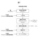
- FIG. 7 shows an outline of the HPAL process in a flow diagram.
- an acid such as concentrated sulfuric acid is added to a valuable metal-containing residue in the form of a slurry in a reactor such as an autoclave under high temperature and pressure to obtain a leaching slurry.
- the valuable metals contained in the valuable metal-containing residue are ionized by reaction with concentrated sulfuric acid and leached into the liquid phase of the leaching slurry.
- a neutralizing agent is added to the leaching slurry in the primary neutralization to adjust the pH to about 1.5. This pH adjustment is intended to precipitate metal ions such as Fe and Al contained in the leaching slurry as oxides in the CCD.
- the leaching slurry is washed in multiple stages by continuous countercurrent decantation (CCD) and separated into a solid-liquid separation into a leachate and a leaching residue.
- Fe is extracted in the leaching residue in the form of hematite (Fe 2 O 3 ). Since the leachate from which Fe, Al, etc. have been separated by the CCD contains traces of Cu, Zn, etc., these elements are separated by adjusting the pH and redox potential of the leachate, and then the pH of the leachate is adjusted to about 5 to selectively separate Ni and Co by precipitation.
- a mixed sulfide precipitate (MSP) of nickel and cobalt sulfide is obtained as a valuable metal-containing intermediate.
- MHP mixed hydroxide precipitate
- These valuable metal-containing intermediates are separated by a solid-liquid separator to obtain a valuable metal-containing product.
- Mn, Mg, etc. are dissolved in the solution from which Ni, Co, and other valuable metals have been removed. Therefore, a final neutralization is performed to remove these alkaline earth metals until the marine discharge standard value is reached.
- a neutralizing agent is added to the solution in the final neutralization to adjust the pH of the solution to about 8.5 to about 9.
- concentrated sulfuric acid produced by the treatment of the exhaust gas from the roasting process included in the pretreatment can be used as part or all of the acid for the HPAL treatment.
- alkaline earth metal carbonates generated by CO2 fixation can be used as neutralizing agents for primary neutralization, final neutralization, and/or tailings dam pH adjustment.
- the HPAL process is used for valuable metal recovery.
- CO2 fixation and non-ferrous metal smelting processes can be highly integrated.
- the valuable metal-containing residue obtained by pretreatment can be used as a raw material for the HPAL process, and the alkaline earth metal carbonates generated by CO2 fixation can be used as neutralizing agents for primary neutralization, final neutralization, tailings dam pH adjustment, etc., which are subsequent steps in the HPAL process.
- concentrated sulfuric acid produced in a sulfuric acid plant can be used as an acid for the HPAL process.
- the systems and methods of the present disclosure can be suitably used for CO2 fixation and valuable metal recovery.
- the systems and methods of the present disclosure can be advantageously used for CO2 fixation and valuable metal recovery.
Landscapes
- Chemical & Material Sciences (AREA)
- Engineering & Computer Science (AREA)
- Chemical Kinetics & Catalysis (AREA)
- Environmental & Geological Engineering (AREA)
- Geochemistry & Mineralogy (AREA)
- General Chemical & Material Sciences (AREA)
- Food Science & Technology (AREA)
- Life Sciences & Earth Sciences (AREA)
- Analytical Chemistry (AREA)
- General Life Sciences & Earth Sciences (AREA)
- Oil, Petroleum & Natural Gas (AREA)
- Geology (AREA)
- Manufacturing & Machinery (AREA)
- Materials Engineering (AREA)
- Mechanical Engineering (AREA)
- Metallurgy (AREA)
- Organic Chemistry (AREA)
- Manufacture And Refinement Of Metals (AREA)
- Mixers Of The Rotary Stirring Type (AREA)
Abstract
Description
[態様1]
縦方向に沿って配置された複数の撹拌室を収容する撹拌容器と、
前記撹拌容器の上部に設けられたスラリー供給口と、
前記撹拌容器の下部に設けられたスラリー排出口と、
前記複数の撹拌室の中央を通って前記縦方向に沿って延びる軸と、
前記軸の一端に取り付けられた撹拌機モーターと、
前記軸に取り付けられた複数の撹拌翼であって、前記複数の撹拌室のそれぞれの内部に前記複数の撹拌翼のうち少なくとも1つが位置する、複数の撹拌翼と、
前記複数の撹拌室のそれぞれの下部に配置された複数のふるい板と
を備える撹拌装置、及び
前記複数の撹拌室のそれぞれの内部に前記複数の撹拌翼とは別個に配置された摩滅媒体
を含む、縦型多段撹拌システムであって、前記ふるい板の目開きが上から下に向かって減少している、縦型多段撹拌システム。
[態様2]
前記ふるい板がウェッジワイヤースクリーンである、態様1に記載の縦型多段撹拌システム。
[態様3]
前記複数の撹拌翼がパドル型である、態様1又は2に記載の縦型多段撹拌システム。
[態様4]
前記複数の撹拌翼が、前記軸の回転方向に対して後方側が低くなるように傾斜している、態様1~3のいずれか一態様に記載の縦型多段撹拌システム。
[態様5]
前記摩滅媒体が球状である、態様1~4のいずれか一態様に記載の縦型多段撹拌システム。
[態様6]
前記摩滅媒体の平均粒径が0.3mm~20mmである、態様1~5のいずれか一態様に記載の縦型多段撹拌システム。
[態様7]
前記摩滅媒体のモース硬度が3以上である、態様1~6のいずれか一態様に記載の縦型多段撹拌システム。
[態様8]
前記撹拌容器は、前記撹拌容器の下部に気体供給口及び前記気体供給口と連通した気体分散ノズルを更に備える、態様1~7のいずれか一態様に記載の縦型多段撹拌システム。
[態様9]
前記気体分散ノズルの開口部が下方に向いている、態様8に記載の縦型多段撹拌システム。
[態様10]
態様1~9のいずれか一態様に記載の縦型多段撹拌システムを複数含み、前記複数の縦型多段撹拌システムが直列に接続されている、装置。
[態様11]
縦方向に沿って配置された複数の撹拌室を収容する撹拌容器と、
前記撹拌容器の上部に設けられたスラリー供給口と、
前記撹拌容器の下部に設けられたスラリー排出口と、
前記撹拌容器の下部に設けられた気体供給口と、
前記複数の撹拌室の中央を通って前記縦方向に沿って延びる軸と、
前記軸の一端に取り付けられた撹拌機モーターと、
前記軸に取り付けられた複数の撹拌翼であって、前記複数の撹拌室のそれぞれの内部に前記複数の撹拌翼のうち少なくとも1つが位置する、複数の撹拌翼と、
前記複数の撹拌室のそれぞれの下部に配置された複数のふるい板と
を備える撹拌装置、及び
前記複数の撹拌室のそれぞれの内部に前記複数の撹拌翼とは別個に配置された摩滅媒体
を含む、縦型多段撹拌システムであって、前記ふるい板の目開きが上から下に向かって減少している、縦型多段撹拌システムを提供すること、
アルカリ土類金属含有粒子及び水性媒体を含むスラリーを前記スラリー供給口に供給すること、
CO2ガスを前記気体供給口に供給すること、
前記スラリーと前記CO2ガスとを前記複数の撹拌室のうち1つの撹拌室内で撹拌混合することにより、前記アルカリ土類金属含有粒子中のアルカリ土類金属のイオンを液相中に抽出し、前記1つの撹拌室の下部に配置された前記ふるい板を通して前記アルカリ土類金属含有粒子を前記1つの撹拌室の下に位置する前記複数の撹拌室のうち別の撹拌室に移動させること、
前記アルカリ土類金属のイオンが前記液相中に抽出された混合物を前記スラリー排出口から取り出した後、固液分離して、前記アルカリ土類金属のイオンを含む液相と、抽出残渣を含む固相とを得ること、及び
前記液相からアルカリ土類金属炭酸塩を析出させて、前記アルカリ土類金属炭酸塩中にCO2を固定化すること
を含むCO2固定化方法。
[態様12]
前記CO2ガスの供給源が、石炭発電所、石油発電所、天然ガス発電所、バイオマス発電所、石炭ボイラー、製錬設備、中和設備、及び焙焼設備からなる群より選ばれる少なくとも1つである、態様11に記載のCO2固定化方法。
[態様13]
原料として供給されるスラリーが、前記アルカリ土類金属含有粒子を0.5質量%~50質量%含む、態様11又は12に記載のCO2固定化方法。
[態様14]
前記スラリーの前記複数の撹拌室における滞留時間が、各撹拌室あたり15分~60分である、態様11~13のいずれか一態様に記載のCO2固定化方法。
一実施形態の縦型多段撹拌システムは、縦方向に沿って配置された複数の撹拌室を収容する撹拌容器と、撹拌容器の上部に設けられたスラリー供給口と、撹拌容器の下部に設けられたスラリー排出口と、複数の撹拌室の中央を通って縦方向に沿って延びる軸と、軸の一端に取り付けられた撹拌機モーターと、軸に取り付けられた複数の撹拌翼であって、複数の撹拌室のそれぞれの内部に複数の撹拌翼のうち少なくとも1つが位置する、複数の撹拌翼と、複数の撹拌室のそれぞれの下部に配置された複数のふるい板とを備える撹拌装置を含む。
図5にCO2固定化方法の概要をフロー図で示す。本開示のフロー図において、四角で囲まれた部分は工程又は装置を示す。図5において、任意工程として、アルカリ土類金属含有原料に対して前処理を行うことにより、アルカリ土類金属含有粒子が得られる。アルカリ土類金属含有粒子に水性媒体を加えてスラリーを得る。スラリーを撹拌しながらCO2ガスと混合することにより、アルカリ土類金属含有粒子中のアルカリ土類金属のイオンが液相中に抽出される。その後、固液分離により、アルカリ土類金属のイオンを含む液相と、抽出残渣を含む固相とが得られる。液相からアルカリ土類金属炭酸塩を析出させて、アルカリ土類金属炭酸塩中にCO2が固定化される。
(1)撹拌容器の下部に設けられた気体供給口を備える前記縦型多段撹拌システムを提供すること、
(2)アルカリ土類金属含有粒子及び水性媒体を含むスラリーをスラリー供給口に供給すること、
(3)CO2ガスを気体供給口に供給すること、
(4)スラリーとCO2ガスとを複数の撹拌室のうち1つの撹拌室内で撹拌混合することにより、アルカリ土類金属含有粒子中のアルカリ土類金属のイオンを液相中に抽出し、1つの撹拌室の下部に配置されたふるい板を通してアルカリ土類金属含有粒子を1つの撹拌室の下に位置する複数の撹拌室のうち別の撹拌室に移動させること、
(5)アルカリ土類金属のイオンが液相中に抽出された混合物をスラリー排出口から取り出した後、固液分離して、アルカリ土類金属のイオンを含む液相と、抽出残渣を含む固相とを得ること、及び
(6)液相からアルカリ土類金属炭酸塩を析出させて、アルカリ土類金属炭酸塩中にCO2を固定化すること
を含む。
前記CO2固定化方法と組み合わせて、有価金属を含むアルカリ土類金属含有原料から有価金属を回収することもできる。一実施形態のCO2を固定化し有価金属を回収する方法は、有価金属と、アルカリ土類金属とを含むアルカリ土類金属含有原料を前処理して、アルカリ土類金属含有粒子と有価金属含有残渣とを得ること;アルカリ土類金属含有粒子を用いて前記CO2固定化方法を実施すること;及び有価金属含有残渣から有価金属を含有する製品、中間体又はそれらの両方を回収することを含む。
2 スラリー供給口
3 撹拌機モーター
4 排ガス出口
5 スラリー分散ノズル
6 軸受
7 摩滅媒体
8 軸
9、9a、9b 撹拌翼
91 翼部
92 ボス部
10、10a、10b ふるい板(ウェッジワイヤースクリーン)
101 ウェッジ
102 支持体
11a、11b 撹拌室
12 撹拌容器
13 気体供給口
14 気体分散ノズル
15 軸受
16 スラリー排出口
17 スラリーポンプ
18 三方弁
19 スラリー循環ライン
20、20a、20b スラリー排出ライン
21 点検口
22 圧力計
23 三方弁
24 スラリー供給ライン
25 二方弁
Claims (14)
- 縦方向に沿って配置された複数の撹拌室を収容する撹拌容器と、
前記撹拌容器の上部に設けられたスラリー供給口と、
前記撹拌容器の下部に設けられたスラリー排出口と、
前記複数の撹拌室の中央を通って前記縦方向に沿って延びる軸と、
前記軸の一端に取り付けられた撹拌機モーターと、
前記軸に取り付けられた複数の撹拌翼であって、前記複数の撹拌室のそれぞれの内部に前記複数の撹拌翼のうち少なくとも1つが位置する、複数の撹拌翼と、
前記複数の撹拌室のそれぞれの下部に配置された複数のふるい板と
を備える撹拌装置、及び
前記複数の撹拌室のそれぞれの内部に前記複数の撹拌翼とは別個に配置された摩滅媒体
を含む、縦型多段撹拌システムであって、前記ふるい板の目開きが上から下に向かって減少している、縦型多段撹拌システム。 - 前記ふるい板がウェッジワイヤースクリーンである、請求項1に記載の縦型多段撹拌システム。
- 前記複数の撹拌翼がパドル型である、請求項1又は2に記載の縦型多段撹拌システム。
- 前記複数の撹拌翼が、前記軸の回転方向に対して後方側が低くなるように傾斜している、請求項1~3のいずれか一項に記載の縦型多段撹拌システム。
- 前記摩滅媒体が球状である、請求項1~4のいずれか一項に記載の縦型多段撹拌システム。
- 前記摩滅媒体の平均粒径が0.3mm~20mmである、請求項1~5のいずれか一項に記載の縦型多段撹拌システム。
- 前記摩滅媒体のモース硬度が3以上である、請求項1~6のいずれか一項に記載の縦型多段撹拌システム。
- 前記撹拌容器は、前記撹拌容器の下部に気体供給口及び前記気体供給口と連通した気体分散ノズルを更に備える、請求項1~7のいずれか一項に記載の縦型多段撹拌システム。
- 前記気体分散ノズルの開口部が下方に向いている、請求項8に記載の縦型多段撹拌システム。
- 請求項1~9のいずれか一項に記載の縦型多段撹拌システムを複数含み、前記複数の縦型多段撹拌システムが直列に接続されている、装置。
- 縦方向に沿って配置された複数の撹拌室を収容する撹拌容器と、
前記撹拌容器の上部に設けられたスラリー供給口と、
前記撹拌容器の下部に設けられたスラリー排出口と、
前記撹拌容器の下部に設けられた気体供給口と、
前記複数の撹拌室の中央を通って前記縦方向に沿って延びる軸と、
前記軸の一端に取り付けられた撹拌機モーターと、
前記軸に取り付けられた複数の撹拌翼であって、前記複数の撹拌室のそれぞれの内部に前記複数の撹拌翼のうち少なくとも1つが位置する、複数の撹拌翼と、
前記複数の撹拌室のそれぞれの下部に配置された複数のふるい板と
を備える撹拌装置、及び
前記複数の撹拌室のそれぞれの内部に前記複数の撹拌翼とは別個に配置された摩滅媒体
を含む、縦型多段撹拌システムであって、前記ふるい板の目開きが上から下に向かって減少している、縦型多段撹拌システムを提供すること、
アルカリ土類金属含有粒子及び水性媒体を含むスラリーを前記スラリー供給口に供給すること、
CO2ガスを前記気体供給口に供給すること、
前記スラリーと前記CO2ガスとを前記複数の撹拌室のうち1つの撹拌室内で撹拌混合することにより、前記アルカリ土類金属含有粒子中のアルカリ土類金属のイオンを液相中に抽出し、前記1つの撹拌室の下部に配置された前記ふるい板を通して前記アルカリ土類金属含有粒子を前記1つの撹拌室の下に位置する前記複数の撹拌室のうち別の撹拌室に移動させること、
前記アルカリ土類金属のイオンが前記液相中に抽出された混合物を前記スラリー排出口から取り出した後、固液分離して、前記アルカリ土類金属のイオンを含む液相と、抽出残渣を含む固相とを得ること、及び
前記液相からアルカリ土類金属炭酸塩を析出させて、前記アルカリ土類金属炭酸塩中にCO2を固定化すること
を含むCO2固定化方法。 - 前記CO2ガスの供給源が、石炭発電所、石油発電所、天然ガス発電所、バイオマス発電所、石炭ボイラー、製錬設備、中和設備、及び焙焼設備からなる群より選ばれる少なくとも1つである、請求項11に記載のCO2固定化方法。
- 原料として供給されるスラリーが、前記アルカリ土類金属含有粒子を0.5質量%~50質量%含む、請求項11又は12に記載のCO2固定化方法。
- 前記スラリーの前記複数の撹拌室における滞留時間が、各撹拌室あたり15分~60分である、請求項11~13のいずれか一項に記載のCO2固定化方法。
Priority Applications (2)
| Application Number | Priority Date | Filing Date | Title |
|---|---|---|---|
| PCT/JP2023/012275 WO2024201669A1 (ja) | 2023-03-27 | 2023-03-27 | 縦型多段撹拌システム及びco2固定化方法 |
| AU2023441035A AU2023441035A1 (en) | 2023-03-27 | 2023-03-27 | Vertical multistage stirring system and co2 sequestration method |
Applications Claiming Priority (1)
| Application Number | Priority Date | Filing Date | Title |
|---|---|---|---|
| PCT/JP2023/012275 WO2024201669A1 (ja) | 2023-03-27 | 2023-03-27 | 縦型多段撹拌システム及びco2固定化方法 |
Publications (1)
| Publication Number | Publication Date |
|---|---|
| WO2024201669A1 true WO2024201669A1 (ja) | 2024-10-03 |
Family
ID=92904240
Family Applications (1)
| Application Number | Title | Priority Date | Filing Date |
|---|---|---|---|
| PCT/JP2023/012275 Ceased WO2024201669A1 (ja) | 2023-03-27 | 2023-03-27 | 縦型多段撹拌システム及びco2固定化方法 |
Country Status (2)
| Country | Link |
|---|---|
| AU (1) | AU2023441035A1 (ja) |
| WO (1) | WO2024201669A1 (ja) |
Citations (4)
| Publication number | Priority date | Publication date | Assignee | Title |
|---|---|---|---|---|
| JPH02500960A (ja) * | 1986-10-09 | 1990-04-05 | イーストマン コダック カンパニー | 微粒子固体物質を浸出する方法 |
| US20050180910A1 (en) * | 2003-12-31 | 2005-08-18 | Ah-Hyung Park | Carbon dioxide sequestration using alkaline earth metal-bearing minerals |
| CN111054488A (zh) * | 2019-12-14 | 2020-04-24 | 安徽儒特实业有限公司 | 一种立式砂磨机 |
| JP2022520927A (ja) * | 2019-02-15 | 2022-04-04 | オムヤ インターナショナル アクチェンゲゼルシャフト | ナノ沈降炭酸カルシウムの製造方法 |
-
2023
- 2023-03-27 AU AU2023441035A patent/AU2023441035A1/en active Pending
- 2023-03-27 WO PCT/JP2023/012275 patent/WO2024201669A1/ja not_active Ceased
Patent Citations (4)
| Publication number | Priority date | Publication date | Assignee | Title |
|---|---|---|---|---|
| JPH02500960A (ja) * | 1986-10-09 | 1990-04-05 | イーストマン コダック カンパニー | 微粒子固体物質を浸出する方法 |
| US20050180910A1 (en) * | 2003-12-31 | 2005-08-18 | Ah-Hyung Park | Carbon dioxide sequestration using alkaline earth metal-bearing minerals |
| JP2022520927A (ja) * | 2019-02-15 | 2022-04-04 | オムヤ インターナショナル アクチェンゲゼルシャフト | ナノ沈降炭酸カルシウムの製造方法 |
| CN111054488A (zh) * | 2019-12-14 | 2020-04-24 | 安徽儒特实业有限公司 | 一种立式砂磨机 |
Also Published As
| Publication number | Publication date |
|---|---|
| AU2023441035A1 (en) | 2025-03-27 |
Similar Documents
| Publication | Publication Date | Title |
|---|---|---|
| US10850231B2 (en) | Carbon dioxide chemical sequestration from industrial emissions by carbonation | |
| JP3705815B2 (ja) | 大気圧における鉱物浸出プロセス | |
| US20070014709A1 (en) | Recovering metals from sulfidic materials | |
| AU2018204491A1 (en) | Hydrometallurgical treatment process for extraction of precious, base and rare elements | |
| Hourn et al. | Commercialisation of the Albion process | |
| AU2013220926B2 (en) | Process for zinc oxide production from ore | |
| RU2275437C1 (ru) | Способ извлечения золота из упорных золотосодержащих руд | |
| CN107208175A (zh) | 用于金属硫化物的高于常压的浸出的系统和方法 | |
| RU2434064C1 (ru) | Способ переработки упорного сульфидного золотосодержащего сырья | |
| ZA200801806B (en) | Method of treating of zinc- and germanium containing solid-phase polymetallic mineral material | |
| WO2024201669A1 (ja) | 縦型多段撹拌システム及びco2固定化方法 | |
| RU2353679C2 (ru) | Извлечение металлов из сульфидных материалов | |
| WO2023223399A1 (ja) | アルカリ土類金属の抽出方法、co2固定化方法、及びco2を固定化し有価金属を回収する方法 | |
| CN104755640B (zh) | 从铅矿渣回收锌 | |
| JP4852716B2 (ja) | 亜鉛精鉱浸出法および浸出装置 | |
| WO2024247105A1 (ja) | Co2固定化方法及びco2固定化装置 | |
| JP2013044045A (ja) | 廃触媒・廃吸着剤の有価金属回収方法及び回収システム | |
| AU2022287623A1 (en) | A process for treating refractory sulphide ore and a solids-gas reactor therefor | |
| RU2339708C1 (ru) | Способ выщелачивания продуктов, содержащих сульфиды металлов | |
| PT1697549E (pt) | Processo de extracção de níquel de um minério de cromite de baixo teor | |
| JP7196630B2 (ja) | 硫酸水溶液からの有価金属の回収方法及び回収設備 | |
| CN112442601A (zh) | 一种提高含碳含碲难选灰岩型金矿石浸出率的工艺 | |
| CN109266844B (zh) | 一种黄铁矿烧渣回转窑提炼铜的方法 | |
| JP7191215B2 (ja) | ニッケル含有原料の処理方法 | |
| JP2025084574A (ja) | Co2固定化装置及びco2固定化方法 |
Legal Events
| Date | Code | Title | Description |
|---|---|---|---|
| 121 | Ep: the epo has been informed by wipo that ep was designated in this application |
Ref document number: 23930309 Country of ref document: EP Kind code of ref document: A1 |
|
| WWE | Wipo information: entry into national phase |
Ref document number: AU2023441035 Country of ref document: AU |
|
| ENP | Entry into the national phase |
Ref document number: 2023441035 Country of ref document: AU Date of ref document: 20230327 Kind code of ref document: A |
|
| NENP | Non-entry into the national phase |
Ref country code: DE |
|
| 122 | Ep: pct application non-entry in european phase |
Ref document number: 23930309 Country of ref document: EP Kind code of ref document: A1 |