WO2024201667A1 - 電解セル - Google Patents
電解セル Download PDFInfo
- Publication number
- WO2024201667A1 WO2024201667A1 PCT/JP2023/012264 JP2023012264W WO2024201667A1 WO 2024201667 A1 WO2024201667 A1 WO 2024201667A1 JP 2023012264 W JP2023012264 W JP 2023012264W WO 2024201667 A1 WO2024201667 A1 WO 2024201667A1
- Authority
- WO
- WIPO (PCT)
- Prior art keywords
- region
- oxygen electrode
- central portion
- metal member
- electrode
- Prior art date
- Legal status (The legal status is an assumption and is not a legal conclusion. Google has not performed a legal analysis and makes no representation as to the accuracy of the status listed.)
- Ceased
Links
Images

Classifications
-
- C—CHEMISTRY; METALLURGY
- C25—ELECTROLYTIC OR ELECTROPHORETIC PROCESSES; APPARATUS THEREFOR
- C25B—ELECTROLYTIC OR ELECTROPHORETIC PROCESSES FOR THE PRODUCTION OF COMPOUNDS OR NON-METALS; APPARATUS THEREFOR
- C25B1/00—Electrolytic production of inorganic compounds or non-metals
- C25B1/01—Products
- C25B1/02—Hydrogen or oxygen
- C25B1/04—Hydrogen or oxygen by electrolysis of water
- C25B1/042—Hydrogen or oxygen by electrolysis of water by electrolysis of steam
-
- C—CHEMISTRY; METALLURGY
- C25—ELECTROLYTIC OR ELECTROPHORETIC PROCESSES; APPARATUS THEREFOR
- C25B—ELECTROLYTIC OR ELECTROPHORETIC PROCESSES FOR THE PRODUCTION OF COMPOUNDS OR NON-METALS; APPARATUS THEREFOR
- C25B1/00—Electrolytic production of inorganic compounds or non-metals
- C25B1/01—Products
- C25B1/23—Carbon monoxide or syngas
-
- C—CHEMISTRY; METALLURGY
- C25—ELECTROLYTIC OR ELECTROPHORETIC PROCESSES; APPARATUS THEREFOR
- C25B—ELECTROLYTIC OR ELECTROPHORETIC PROCESSES FOR THE PRODUCTION OF COMPOUNDS OR NON-METALS; APPARATUS THEREFOR
- C25B11/00—Electrodes; Manufacture thereof not otherwise provided for
- C25B11/02—Electrodes; Manufacture thereof not otherwise provided for characterised by shape or form
- C25B11/03—Electrodes; Manufacture thereof not otherwise provided for characterised by shape or form perforated or foraminous
- C25B11/031—Porous electrodes
-
- C—CHEMISTRY; METALLURGY
- C25—ELECTROLYTIC OR ELECTROPHORETIC PROCESSES; APPARATUS THEREFOR
- C25B—ELECTROLYTIC OR ELECTROPHORETIC PROCESSES FOR THE PRODUCTION OF COMPOUNDS OR NON-METALS; APPARATUS THEREFOR
- C25B9/00—Cells or assemblies of cells; Constructional parts of cells; Assemblies of constructional parts, e.g. electrode-diaphragm assemblies; Process-related cell features
- C25B9/17—Cells comprising dimensionally-stable non-movable electrodes; Assemblies of constructional parts thereof
- C25B9/19—Cells comprising dimensionally-stable non-movable electrodes; Assemblies of constructional parts thereof with diaphragms
- C25B9/23—Cells comprising dimensionally-stable non-movable electrodes; Assemblies of constructional parts thereof with diaphragms comprising ion-exchange membranes in or on which electrode material is embedded
-
- C—CHEMISTRY; METALLURGY
- C25—ELECTROLYTIC OR ELECTROPHORETIC PROCESSES; APPARATUS THEREFOR
- C25B—ELECTROLYTIC OR ELECTROPHORETIC PROCESSES FOR THE PRODUCTION OF COMPOUNDS OR NON-METALS; APPARATUS THEREFOR
- C25B9/00—Cells or assemblies of cells; Constructional parts of cells; Assemblies of constructional parts, e.g. electrode-diaphragm assemblies; Process-related cell features
- C25B9/60—Constructional parts of cells
- C25B9/65—Means for supplying current; Electrode connections; Electric inter-cell connections
-
- Y—GENERAL TAGGING OF NEW TECHNOLOGICAL DEVELOPMENTS; GENERAL TAGGING OF CROSS-SECTIONAL TECHNOLOGIES SPANNING OVER SEVERAL SECTIONS OF THE IPC; TECHNICAL SUBJECTS COVERED BY FORMER USPC CROSS-REFERENCE ART COLLECTIONS [XRACs] AND DIGESTS
- Y02—TECHNOLOGIES OR APPLICATIONS FOR MITIGATION OR ADAPTATION AGAINST CLIMATE CHANGE
- Y02E—REDUCTION OF GREENHOUSE GAS [GHG] EMISSIONS, RELATED TO ENERGY GENERATION, TRANSMISSION OR DISTRIBUTION
- Y02E60/00—Enabling technologies; Technologies with a potential or indirect contribution to GHG emissions mitigation
- Y02E60/30—Hydrogen technology
- Y02E60/36—Hydrogen production from non-carbon containing sources, e.g. by water electrolysis
Definitions
- the present invention relates to an electrolysis cell.
- an electrolysis cell including a cell body having an electrolyte disposed between a hydrogen electrode and an oxygen electrode (see, for example, Patent Document 1).
- a raw material gas is supplied to the hydrogen electrode, and oxygen (O 2 ) is produced at the oxygen electrode.
- the electrolytic cell may have a metal member that is in contact with or faces the oxygen electrode.
- the metal member include a separator used to stack the electrolytic cells and a current collecting member used to collect current.
- the oxygen generated at the oxygen electrode may cause a noticeable oxide film to grow on the surface of the metal components.
- the amount of oxygen generated is likely to increase due to current concentration caused by a rise in temperature due to heat buildup.
- the part of the metal member that is in contact with or facing the center of the oxygen electrode is exposed to a highly oxidizing atmosphere.
- the performance of the electrolysis cell is reduced due to the significant growth of an oxide film on the part of the metal member that is in contact with or facing the center of the oxygen electrode.
- the objective of the present invention is to provide an electrolysis cell that can suppress performance degradation.
- the electrolytic cell according to the first aspect of the present invention comprises a cell main body and a metal member.
- the cell main body has a hydrogen electrode, an oxygen electrode, and an electrolyte disposed between the hydrogen electrode and the oxygen electrode.
- the metal member is electrically connected to the oxygen electrode.
- the oxygen electrode has a first region within 5 ⁇ m from the surface of the metal member and a second region more than 5 ⁇ m from the surface of the metal member.
- the first region includes a central portion and an outer peripheral portion surrounding the central portion.
- the porosity of the central portion is smaller than the porosity of the outer peripheral portion.
- the electrolytic cell according to the second aspect of the present invention is the same as the first aspect, and the porosity of the second region is greater than the porosity of the central portion.
- the present invention provides an electrolysis cell that can suppress performance degradation.
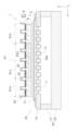
- FIG. 1 is a plan view of an electrolysis cell according to an embodiment.
- FIG. 2 is a cross-sectional view taken along line AA of FIG.
- FIG. 1 is a plan view of an electrolysis cell 1 according to an embodiment.
- Fig. 2 is a cross-sectional view taken along line A-A in Fig. 1.
- Fig. 2 shows a cross section passing through a geometric center CP of an oxygen electrode 9, which will be described later.
- a metal member 25 is omitted in Fig. 1.
- Electrolytic cell 1 is a so-called metal-supported electrolytic cell.
- the electrolytic cell 1 is formed in a plate shape extending in the X-axis and Y-axis directions.
- the electrolytic cell 1 is formed in a rectangular shape extending in the Y-axis direction when viewed in a plan view from the Z-axis direction perpendicular to the X-axis and Y-axis directions.
- the planar shape of the electrolytic cell 1 is not particularly limited, and may be a polygon other than a rectangle, an ellipse, a circle, etc.
- the X-axis direction and the Y-axis direction are the surface directions of the electrolytic cell 1
- the Z-axis direction is the thickness direction of the electrolytic cell 1.
- the electrolysis cell 1 includes a metal support 10, a cell body 20, a metal member 25, and a flow path member 30.
- the metal support 10 supports the cell main body 20.
- the metal support 10 is formed in a plate shape.
- the metal support 10 may be in the shape of a flat plate or a curved plate.
- the metal support 10 may have any thickness as long as it can support the cell main body 20, and may have any thickness, for example, 0.1 mm or more and 2.0 mm or less.
- the thermal expansion coefficient of the metal support 10 is not particularly limited, and may have any thermal expansion coefficient, for example, 10 ⁇ 10 ⁇ 6 /° C. or more and 18 ⁇ 10 ⁇ 6 /° C. or less.
- the metal support 10 has a plurality of communication holes 11, a first main surface 12, and a second main surface 13.
- Each communication hole 11 penetrates the metal support 10 from the first main surface 12 to the second main surface 13. Each communication hole 11 opens to both the first main surface 12 and the second main surface 13. The opening of each communication hole 11 on the first main surface 12 side is covered by the hydrogen electrode 6. The opening of each communication hole 11 on the second main surface 13 side is connected to a flow path 30a described below.
- Each communication hole 11 can be formed by mechanical processing (e.g., punching), laser processing, or chemical processing (e.g., etching).
- each communication hole 11 is formed linearly along the Z-axis direction.
- each communication hole 11 may be inclined with respect to the Z-axis direction, and may not be linear.
- the communication holes 11 may be connected to each other.
- the first main surface 12 is provided on the opposite side to the second main surface 13.
- the cell main body 20 is disposed on the first main surface 12.
- the flow path member 30 is bonded to the second main surface 13.
- the metal support 10 is made of a metal material.
- the metal support 10 is made of an alloy material containing Cr (chromium).
- Examples of such metal materials include Fe-Cr alloy steel (stainless steel, etc.) and Ni-Cr alloy steel.
- Cr content in the metal support 10 can be 4% by mass or more and 30% by mass or less.
- the metal support 10 may contain Ti (titanium) and Zr (zirconium).
- the Ti content in the metal support 10 is not particularly limited, but may be 0.01 mol% or more and 1.0 mol% or less.
- the Al content in the metal support 10 is not particularly limited, but may be 0.01 mol% or more and 0.4 mol% or less.
- the metal support 10 may contain Ti as TiO2 (titania) and Zr as ZrO2 (zirconia).
- the metal support 10 may have an oxide film on its surface that is formed by oxidation of the constituent elements of the metal support 10.
- a typical example of the oxide film is a chromium oxide film.
- the chromium oxide film covers at least a portion of the surface of the metal support 10.
- the chromium oxide film may also cover at least a portion of the inner wall surface of each communication hole 11.
- the cell body 20 is disposed on the metal support 10.
- the cell body 20 is supported by the metal support 10.
- the cell body 20 has a hydrogen electrode 6 (cathode), an electrolyte 7, a reaction prevention layer 8, and an oxygen electrode 9 (anode).
- the hydrogen electrode 6, electrolyte 7, reaction prevention layer 8, and oxygen electrode 9 are layered in this order in the Z-axis direction from the metal support 10 side.
- the hydrogen electrode 6, electrolyte 7, and oxygen electrode 9 are required components, while the reaction prevention layer 8 is optional.
- the hydrogen electrode 6 is disposed between the metal support 10 and the electrolyte 7.
- the hydrogen electrode 6 is formed on a first main surface 12 of the metal support 10. In this embodiment, a portion of the hydrogen electrode 6 is disposed inside each of the communication holes 11 of the metal support 10, but the hydrogen electrode 6 does not have to extend into each of the communication holes 11 of the metal support 10.
- a source gas is supplied to the hydrogen electrode 6 through each communication hole 11.
- the source gas contains at least H2O .
- the hydrogen electrode 6 produces H 2 from the source gas in accordance with the electrochemical reaction of water electrolysis shown in the following formula (1).
- Hydrogen electrode 6 H 2 O + 2e ⁇ ⁇ H 2 + O 2 ⁇ (1)
- the hydrogen electrode 6 produces H 2 , CO, and O 2 ⁇ from the source gas in accordance with the co-electrochemical reactions shown in the following formulas (2), (3), and (4).
- Hydrogen electrode 6 CO 2 + H 2 O + 4e ⁇ ⁇ CO + H 2 + 2O 2 ⁇ (2) Electrochemical reaction of H 2 O: H 2 O + 2e ⁇ ⁇ H 2 + O 2 ⁇ (3) Electrochemical reaction of CO2 : CO2 + 2e- ⁇ CO + O2 -... (4)
- the hydrogen electrode 6 is a porous body having electronic conductivity.
- the hydrogen electrode 6 contains nickel (Ni) and an oxide ion conductive material.
- Ni functions as an electronic conductor. In the case of co-electrolysis, Ni also functions as a thermal catalyst to promote the thermal reaction between the generated H2 and the CO2 contained in the feed gas to maintain a suitable gas composition for methanation, reverse water gas shift reaction, etc. Ni exists in the form of nickel oxide (NiO) in an oxidizing atmosphere and in the form of metallic Ni in a reducing atmosphere.
- NiO nickel oxide
- oxide ion conductive materials examples include YSZ, CSZ, ScSZ, GDC, SDC, (La,Sr)(Cr,Mn) O3 , (La,Sr) TiO3 , Sr2 (Fe,Mo) 2O6 , ( La ,Sr) VO3 , (La,Sr) FeO3 , and mixed materials of two or more of these.
- the thickness of the hydrogen electrode 6 is not particularly limited, but can be, for example, 1 ⁇ m or more and 100 ⁇ m or less.
- the method for forming the hydrogen electrode 6 is not particularly limited, and may be a sintering method, a spray coating method (thermal spraying, aerosol deposition, aerosol gas deposition, powder jet deposition, particle jet deposition, cold spray, etc.), a PVD method (sputtering, pulsed laser deposition, etc.), a CVD method, etc.
- the electrolyte 7 is disposed between the hydrogen electrode 6 and the oxygen electrode 9.
- the reaction prevention layer 8 is disposed between the electrolyte 7 and the oxygen electrode 9, so that the electrolyte 7 is sandwiched between the hydrogen electrode 6 and the reaction prevention layer 8.
- the electrolyte 7 covers the hydrogen electrode 6 and also covers the area of the first main surface 12 of the metal support 10 that is exposed from the hydrogen electrode 6.
- the electrolyte 7 transfers O 2- generated at the hydrogen electrode 6 to the oxygen electrode 9.
- the electrolyte 7 is made of a dense material having oxide ion conductivity.
- the electrolyte 7 can be made of, for example, YSZ (yttria-stabilized zirconia, e.g., 8YSZ), GDC (gadolinium-doped ceria), ScSZ (scandia-stabilized zirconia), SDC (samarium-doped ceria), LSGM (lanthanum gallate), or the like.
- the porosity of the electrolyte 7 is not particularly limited, but can be, for example, 0.1% to 7%.
- the thickness of the electrolyte 7 is not particularly limited, but can be, for example, 1 ⁇ m to 100 ⁇ m.
- the method for forming the electrolyte 7 is not particularly limited, and a baking method, a spray coating method, a PVD method, a CVD method, etc. can be used.
- reaction prevention layer 8 The reaction prevention layer 8 is disposed between the electrolyte 7 and the oxygen electrode 9. The reaction prevention layer 8 is disposed on the opposite side of the electrolyte 7 to the hydrogen electrode 6. The reaction prevention layer 8 prevents a layer having a high electrical resistance from being formed due to a reaction between a constituent element of the electrolyte 7 and a constituent element of the oxygen electrode 9.
- the reaction prevention layer 8 is made of an oxide ion conductive material.
- the reaction prevention layer 8 can be made of GDC, SDC, etc.
- the porosity of the reaction prevention layer 8 is not particularly limited, but can be, for example, 0.1% to 50%.
- the thickness of the reaction prevention layer 8 is not particularly limited, but can be, for example, 1 ⁇ m to 50 ⁇ m.
- the method for forming the reaction prevention layer 8 is not particularly limited, and a baking method, a spray coating method, a PVD method, a CVD method, etc. can be used.
- the oxygen electrode 9 is disposed on the opposite side of the hydrogen electrode 6 with respect to the electrolyte 7. In this embodiment, since the reaction prevention layer 8 is disposed between the electrolyte 7 and the oxygen electrode 9, the oxygen electrode 9 is connected to the reaction prevention layer 8. If the reaction prevention layer 8 is not disposed between the electrolyte 7 and the oxygen electrode 9, the oxygen electrode 9 is connected to the electrolyte 7.
- the oxygen electrode 9 has a surface 93 on the metal member 25 side (hereinafter referred to as the "metal member side surface").
- the oxygen electrode 9 produces oxygen (O 2 ) from O 2 ⁇ transferred from the hydrogen electrode 6 via the electrolyte 7 in accordance with the chemical reaction of the following formula (5).
- Oxygen electrode 9 2O 2 ⁇ ⁇ O 2 + 4e ⁇ (5)
- the porosity of the oxygen electrode 9 is not particularly limited, but can be, for example, 20% or more and 60% or less.
- the thickness of the oxygen electrode 9 is not particularly limited, but can be, for example, 1 ⁇ m or more and 100 ⁇ m or less. The detailed configuration of the oxygen electrode 9 will be described later.
- the method for forming the oxygen electrode 9 is not particularly limited, and methods such as baking, spray coating, PVD, and CVD can be used.
- the metal member 25 is electrically connected to the oxygen electrode 9.
- the metal member 25 is electrically connected to the oxygen electrode 9 via a conductive bonding material 26.
- the metal member 25 may be electrically connected to the oxygen electrode 9 by direct contact with the oxygen electrode 9. In this case, the metal member 25 does not need to be fixed to the oxygen electrode 9.
- the metal member 25 in this embodiment functions as a current collecting member.
- the metal member 25 is electrically connected to the interconnector 32 (described later) that is provided in the other electrolysis cells.
- the metal member 25 may be made of, for example, ferritic stainless steel, but the material of the metal member 25 is not particularly limited.
- the surface of the metal member 25 may be covered with a conductive coating.
- At least a portion of the surface of the metal member 25 may be covered with an oxide film formed by oxidation of the constituent elements of the metal member 25.
- a typical example of the oxide film is a chromium oxide film. When an oxide film is present, the oxide film is considered to constitute a part of the metal member 25.
- At least a portion of the surface of the metal member 25, or at least a portion of the oxide film covering the surface of the metal member 25, may be covered with an oxidation-resistant coating film.
- a typical example of an oxidation-resistant coating film is a manganese-cobalt composite oxide film.
- the oxide film constitutes a part of the metal member 25.
- the oxidation-resistant coating film constitutes a part of the metal member 25.
- the oxidation-resistant coating film can suppress the oxidation of the metal member 25, it is generally difficult to completely prevent the oxidation of the metal member 25 using the oxidation-resistant coating film.
- the metal member 25 is exposed to a strongly oxidizing atmosphere, the oxidation of the metal member 25 cannot be completely prevented even if an oxidation-resistant coating film is formed, and an oxide film grows on the surface of the metal member 25.
- the flow path member 30 is joined to the second main surface 13 of the metal support 10.
- the flow path member 30 forms a flow path 30a between itself and the metal support 10.
- a source gas is supplied to the flow path 30a.
- the source gas supplied to the flow path 30a is supplied to the hydrogen electrode 6 of the cell main body 20 through each communication hole 11 of the metal support 10.
- the flow path member 30 can be made of, for example, an alloy material.
- the flow path member 30 may be made of the same material as the metal support 10. In this case, the flow path member 30 may be substantially integral with the metal support 10.
- the flow path member 30 has a frame body 31 and an interconnector 32.
- the frame body 31 is an annular member that surrounds the side of the flow path 30a.
- the frame body 31 is joined to the second main surface 13 of the metal support body 10.
- the interconnector 32 is a plate-shaped member for electrically connecting an external power source or another electrolysis cell in series with the electrolysis cell 1.
- the interconnector 32 is joined to the frame body 31.
- the frame body 31 and the interconnector 32 are separate members, but the frame body 31 and the interconnector 32 may be an integrated member.
- the oxygen electrode 9 has a first region 91 and a second region 92.
- the first region 91 is a region of the oxygen electrode 9 that is within 5 ⁇ m from the metal member side surface 93.
- the second region 92 is a region of the oxygen electrode 9 that is more than 5 ⁇ m from the metal member side surface 93. In other words, the second region 92 is a region of the oxygen electrode 9 excluding the first region 91.
- the first region 91 is made of a porous material having electron conductivity.
- the first region 91 may be made of, for example, one or more of (La,Sr)(Co,Fe) O3 , (La,Sr) FeO3 , La(Ni,Fe) O3 , (La,Sr)CoO3, (Sm,Sr) CoO3 , La(Ni,Fe,Cu) O3 , and (La,Sr) MnO3 .
- the first region 91 may further include an oxide ion conductive material (such as GDC).
- the second region 92 is made of a porous material having electron conductivity.
- the first region 91 can be made of, for example, one or more of (La,Sr)(Co,Fe) O3 , (La,Sr) FeO3 , La(Ni,Fe) O3 , (La,Sr)CoO3, (Sm,Sr) CoO3 , La(Ni,Fe,Cu) O3 , and (La,Sr) MnO3 .
- the second region 92 may further include an oxide ion conductive material (such as GDC).
- composition of the first region 91 may be the same as or different from the composition of the second region 92.
- the central portion 91a is a portion including the geometric center CP of the oxygen electrode 9 in plan view.
- the planar shape of the oxygen electrode 9 in plan view is rectangular, and the planar shape of the central portion 91a in plan view is also rectangular.
- the central portion 91a is located inside the oxygen electrode 9.
- the planar shape of the central portion 91a is similar to the planar shape of the oxygen electrode 9.
- the predetermined magnification is not particularly limited, but can be, for example, 1.2 times or more and 4 times or less. In this embodiment, the predetermined magnification is 2.0 times, and when the outer edge of the central portion 91a is enlarged by 2 times, it becomes congruent with the outer edge of the oxygen electrode 9.
- the planar shape and size of each of the oxygen electrode 9 and the central portion 91a can be changed as appropriate. Therefore, the planar shapes of the oxygen electrode 9 and the central portion 91a may each be a shape other than a rectangle (for example, a polygon other than a rectangle, an ellipse, a circle, etc.). The planar shape of the central portion 91a may also be different from the planar shape of the oxygen electrode 9. The total area of the oxygen electrodes 9 in a planar view can be 1.44 to 16 times the area of the central portion 91a in a planar view.
- the outer peripheral portion 91b is a portion that surrounds the central portion 91a in a plan view.
- the outer peripheral portion 91b is formed in a ring shape in a plan view.
- the planar shape of the outer peripheral portion 91b can be changed as appropriate according to the planar shapes of the oxygen electrode 9 and the central portion 91a.
- the porosity of the central portion 91a is smaller than that of the outer peripheral portion 91b. This can prevent the oxide film from growing significantly on the metal member 25. Specifically, this is as follows. In the oxygen electrode 9, heat is likely to accumulate in the central portion 92a (see FIG. 2) of the second region 92, which is in contact with the central portion 91a of the first region 91. Therefore, a large amount of oxygen is generated in the central portion 92a due to current concentration caused by a rise in temperature. However, since the porosity of the central portion 91a is smaller than that of the outer peripheral portion 91b, the oxygen generated in the central portion 92a is likely to flow toward the outer peripheral portion 91b rather than the central portion 91a.
- the porosity of the second region 92 is preferably greater than the porosity of the central portion 91a. This allows oxygen generated in the central portion 92a of the second region 92 to flow more easily toward the outer periphery 91b. This makes it possible to further suppress the growth of an oxide film in the portion of the metal member 25 that comes into contact with the central portion 91a.
- the porosity of the central portion 91a is not particularly limited, but can be, for example, 20% to 40%.
- the porosity of the outer peripheral portion 91b is not particularly limited, but can be, for example, 25% to 45%.
- the porosity of the second region 92 is not particularly limited, but can be, for example, 20% or more and 45% or less.
- the porosity of the outer peripheral portion 91b of the first region 91 is calculated by dividing the total area of the pores by the total area of the backscattered electron image of the outer peripheral portion 91b, similar to the porosity of the central portion 91a.
- the oxygen electrode 9 is produced by forming a second region 92 on the reaction prevention layer 8 using the constituent material for the second region, forming a central portion 91a on the second region 92 using the constituent material for the central portion of the first region 91, and then forming a peripheral portion 91b surrounding the central portion 91a using the constituent material for the peripheral portion of the first region 91.
- the porosity of each of the central portion 91a of the first region 91, the outer peripheral portion 91b of the first region 91, and the second region 92 can be adjusted by the amount of pore-forming material added, the particle size of the raw material powder, the material composition, and the material type, but adjustment by the amount of pore-forming material added is preferred because it has little effect on electrode performance.
- the metal member 25 functions as a current collecting member, but is not limited thereto.
- the metal member 25 may be electrically connected to the air electrode 9.
- the metal member 25 may be an interconnector 32 provided in another electrolysis cell.
- the metal support type electrolytic cell 1 has been described as an example of an electrolytic cell.
- the electrolytic cell according to the present invention may be a flat plate type that does not include a metal support 10.
- a slurry for the hydrogen electrode layer was prepared by mixing GDC powder, NiO powder, butyral resin, polymethyl methacrylate beads as a pore-forming material, a plasticizer, a dispersant, and a solvent.
- the slurry for the hydrogen electrode layer was then printed on the first main surface of the metal support by the doctor blade method to form a hydrogen electrode layer compact.
- a slurry for the electrolyte layer was prepared by mixing YSZ powder, butyral resin, plasticizer, dispersant, and solvent.
- the electrolyte slurry was then printed using a doctor blade method to cover the green body of the hydrogen electrode layer, forming a green body for the electrolyte layer.
- a slurry for the reaction prevention layer was prepared by mixing GDC powder, polyvinyl alcohol, and a solvent.
- the slurry for the reaction prevention layer was then printed on the electrolyte layer compact by the doctor blade method to form a reaction prevention layer compact.
- the molded bodies of the hydrogen electrode layer, electrolyte layer, and reaction prevention layer arranged in sequence on the metal support were fired in air (1050°C, 1 hour) to form the hydrogen electrode layer, electrolyte layer, and reaction prevention layer.
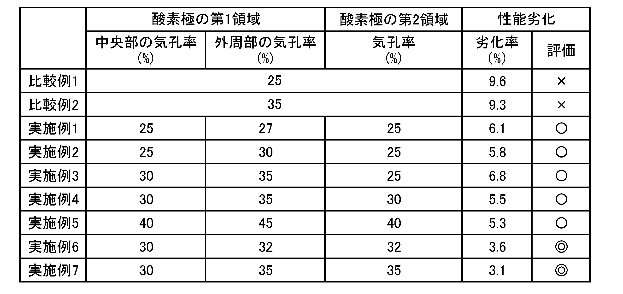
- a slurry for the oxygen electrode layer was prepared by mixing (La, Sr) (Co, Fe) O3 powder, polyvinyl alcohol, a solvent, and a pore former. At this time, the amount of the pore former added was adjusted to change the porosity of the entire oxygen electrode for each comparative example, as shown in Table 1. Then, the slurry for the oxygen electrode layer was printed on the reaction prevention layer by the doctor blade method to form a compact for the oxygen electrode layer.
- the oxygen electrode layer compact was sintered in air (1000°C, 1 hour) to form the oxygen electrode.
- Examples 1 to 7 Electrolytic cells according to Examples 1 to 7 were fabricated in the same manner as in Comparative Examples 1 and 2, except that the oxygen electrode layer had a two-layer structure.
- a slurry for the second region was prepared by mixing (La, Sr) (Co, Fe) O3 powder, polyvinyl alcohol, a solvent, and a pore former.
- the amount of the pore former added was adjusted to change the porosity of the second region of the oxygen electrode for each example, as shown in Table 1.
- the slurry for the second region was printed on the reaction prevention layer by a doctor blade method to form a compact for the second region of the oxygen electrode.
- a slurry for the center of the first region was prepared by mixing (La,Sr)(Co,Fe) O3 powder, polyvinyl alcohol, a solvent, and a pore former.
- the amount of the pore former added was adjusted to change the porosity of the center of the first region of the oxygen electrode for each example, as shown in Table 1.
- the slurry for the center of the first region was printed on the center of the compact for the second region by a doctor blade method, thereby forming a compact for the center of the first region of the oxygen electrode.
- a slurry for the outer periphery of the first region was prepared by mixing (La, Sr) (Co, Fe) O 3 powder, polyvinyl alcohol, a solvent, and a pore former.
- the amount of the pore former added was adjusted to change the porosity of the outer periphery of the first region of the oxygen electrode for each example, as shown in Table 1.
- the slurry for the outer periphery of the first region was printed by a doctor blade method so as to surround the compact of the first region, thereby forming a compact of the outer periphery of the first region of the oxygen electrode.
- the molded bodies of the first and second regions were sintered in air (1000°C, 1 hour) to form an oxygen electrode.
- a mixed gas of water vapor and hydrogen (mixing ratio 90:10) was supplied to the hydrogen electrode layer while a mixed gas of oxygen and nitrogen (mixing ratio 21:79) was supplied to the oxygen electrode layer, and a current was passed so that the current density per hydrogen electrode layer area was constant at 0.5 A/ cm2 to perform electrolysis, and the cell voltage (hereinafter referred to as "initial cell voltage”) was measured.
- cell voltage after durability test the cell voltage after 1000 hours of holding in a state where the current density was fixed at 0.5 A/cm 2 while supplying the mixed gas to each of the hydrogen electrode layer and the oxygen electrode layer.
- Performance degradation rate (%) 100 ⁇ (cell voltage after durability test - initial cell voltage) / initial cell voltage... (6)
- a performance degradation rate of less than 4% was evaluated as "A”
- a performance degradation rate of 4% or more and less than 7% was evaluated as "O”
- a performance degradation rate of 7% or more was evaluated as "X”.
- Electrolysis cell 10
- Metal support 11 Through hole 12
- First main surface 13
- Second main surface 20
- Cell body 6
- Hydrogen electrode 7
- Electrolyte 8
- Reaction prevention layer 9
- Oxygen electrode 91
- First region 91a Central portion 91b Outer peripheral portion 92
- Second region 92a Central portion 30
- Flow path member 30a Flow path
Landscapes
- Chemical & Material Sciences (AREA)
- Engineering & Computer Science (AREA)
- Chemical Kinetics & Catalysis (AREA)
- Electrochemistry (AREA)
- Materials Engineering (AREA)
- Metallurgy (AREA)
- Organic Chemistry (AREA)
- Inorganic Chemistry (AREA)
- Electrolytic Production Of Non-Metals, Compounds, Apparatuses Therefor (AREA)
Abstract
Description
図1は、実施形態に係る電解セル1の平面図である。図2は、図1のA-A断面図である。図2には、後述する酸素極9の幾何中心CPを通る断面が図示されている。ただし、図1では、金属部材25が省略されている。
金属支持体10は、セル本体部20を支持する。金属支持体10は、板状に形成される。金属支持体10は、平板状であってもよいし、曲板状であってもよい。
セル本体部20は、金属支持体10上に配置される。セル本体部20は、金属支持体10によって支持される。セル本体部20は、水素極6(カソード)、電解質7、反応防止層8、及び酸素極9(アノード)を有する。
水素極6は、金属支持体10及び電解質7の間に配置される。水素極6は、金属支持体10の第1主面12上に形成される。本実施形態では、水素極6の一部が、金属支持体10の各連通孔11の内側に配置されているが、水素極6は、金属支持体10の各連通孔11に入り込んでいなくてもよい。
・H2Oの電気化学反応:H2O+2e-→H2+O2-・・・(3)
・CO2の電気化学反応:CO2+2e-→CO+O2-・・・(4)
電解質7は、水素極6及び酸素極9の間に配置される。本実施形態では、電解質7及び酸素極9の間に反応防止層8が配置されているので、電解質7は、水素極6及び反応防止層8の間に挟まれている。
反応防止層8は、電解質7及び酸素極9の間に配置される。反応防止層8は、電解質7を基準として水素極6の反対側に配置される。反応防止層8は、電解質7の構成元素が酸素極9の構成元素と反応して電気抵抗の大きい層が形成されることを抑制する。
酸素極9は、電解質7を基準として水素極6の反対側に配置される。本実施形態では、電解質7及び酸素極9の間に反応防止層8が配置されているので、酸素極9は反応防止層8に接続される。電解質7及び酸素極9の間に反応防止層8が配置されない場合、酸素極9は電解質7に接続される。
金属部材25は、酸素極9と電気的に接続される。本実施形態において、金属部材25は、導電性接合材26を介して、酸素極9と電気的に接続されている。ただし、金属部材25は、酸素極9と直接接触することによって電気的に接続されていてもよい。この場合、金属部材25は、酸素極9に固定されていなくてもよい。
流路部材30は、金属支持体10の第2主面13に接合される。流路部材30は、金属支持体10との間に流路30aを形成する。流路30aには、原料ガスが供給される。流路30aに供給された原料ガスは、金属支持体10の各連通孔11を介して、セル本体部20の水素極6に供給される。
図2に示すように、酸素極9は、第1領域91と第2領域92とを有する。第1領域91は、酸素極9のうち金属部材側表面93から5μm以内の領域である。第2領域92は、酸素極9のうち金属部材側表面93から5μm超の領域である。すなわち、第2領域92は、酸素極9のうち第1領域91を除いた領域である。
以上、本発明の実施形態について説明したが、本発明はこれらに限定されるものではなく、本発明の趣旨を逸脱しない限りにおいて種々の変更が可能である。
上記実施形態において、金属部材25は、集電部材として機能することとしたが、これに限られない。金属部材25は、空気極9と電気的に接続されていればよい。例えば、金属部材25は、他の電解セルが備えるインターコネクタ32であってもよい。
上記実施形態では、電解セルの一例として、メタルサポート型の電解セル1について説明したが、本発明に係る電解セルは、金属支持体10を備えていない平板型であってもよい。
比較例1,2に係る電解セルを次の通り作製した。
酸素極層を二層構造にしたこと以外は上記比較例1,2と同じ工程にて実施例1~7に係る電解セルを作製した。
まず、実施例1~7及び比較例1,2の電解セルを700℃まで昇温した状態で、酸素極層に空気を供給しながら水素極層に水素を供給することによって、水素極層が含有するNiOをNiに還元した。
表1では、性能低下率が4%未満の場合を「◎」と評価し、4%以上7%未満の場合を「〇」と評価し、7%以上の場合を「×」と評価した。
10 金属支持体
11 連通孔
12 第1主面
13 第2主面
20 セル本体部
6 水素極
7 電解質
8 反応防止層
9 酸素極
91 第1領域
91a 中央部
91b 外周部
92 第2領域
92a 中央部
30 流路部材
30a 流路
Claims (2)
- 水素極と、酸素極と、前記水素極及び前記酸素極の間に配置される電解質とを有するセル本体部と、
前記酸素極と電気的に接続される金属部材と、
を備え、
前記酸素極は、金属部材側表面から5μm以内の第1領域と、前記金属部材側表面から5μm超の第2領域とを有し、
前記第1領域は、中央部と、前記中央部を取り囲む外周部とを含み、
前記中央部の気孔率は、前記外周部の気孔率より小さい、
電解セル。 - 前記第2領域の気孔率は、前記中央部の気孔率より大きい、
電解セル。
Priority Applications (2)
| Application Number | Priority Date | Filing Date | Title |
|---|---|---|---|
| PCT/JP2023/012264 WO2024201667A1 (ja) | 2023-03-27 | 2023-03-27 | 電解セル |
| JP2025509295A JPWO2024201667A1 (ja) | 2023-03-27 | 2023-03-27 |
Applications Claiming Priority (1)
| Application Number | Priority Date | Filing Date | Title |
|---|---|---|---|
| PCT/JP2023/012264 WO2024201667A1 (ja) | 2023-03-27 | 2023-03-27 | 電解セル |
Publications (1)
| Publication Number | Publication Date |
|---|---|
| WO2024201667A1 true WO2024201667A1 (ja) | 2024-10-03 |
Family
ID=92903545
Family Applications (1)
| Application Number | Title | Priority Date | Filing Date |
|---|---|---|---|
| PCT/JP2023/012264 Ceased WO2024201667A1 (ja) | 2023-03-27 | 2023-03-27 | 電解セル |
Country Status (2)
| Country | Link |
|---|---|
| JP (1) | JPWO2024201667A1 (ja) |
| WO (1) | WO2024201667A1 (ja) |
Citations (3)
| Publication number | Priority date | Publication date | Assignee | Title |
|---|---|---|---|---|
| JPH0757737A (ja) * | 1993-08-19 | 1995-03-03 | Mitsubishi Heavy Ind Ltd | 固体電解質型電解セルの溶射用電極材料 |
| WO2018198352A1 (ja) * | 2017-04-28 | 2018-11-01 | 株式会社 東芝 | 固体酸化物電気化学セル及びその製造方法 |
| WO2022045141A1 (ja) * | 2020-08-24 | 2022-03-03 | 京セラ株式会社 | セル、セルスタック装置、モジュールおよびモジュール収容装置 |
-
2023
- 2023-03-27 WO PCT/JP2023/012264 patent/WO2024201667A1/ja not_active Ceased
- 2023-03-27 JP JP2025509295A patent/JPWO2024201667A1/ja active Pending
Patent Citations (3)
| Publication number | Priority date | Publication date | Assignee | Title |
|---|---|---|---|---|
| JPH0757737A (ja) * | 1993-08-19 | 1995-03-03 | Mitsubishi Heavy Ind Ltd | 固体電解質型電解セルの溶射用電極材料 |
| WO2018198352A1 (ja) * | 2017-04-28 | 2018-11-01 | 株式会社 東芝 | 固体酸化物電気化学セル及びその製造方法 |
| WO2022045141A1 (ja) * | 2020-08-24 | 2022-03-03 | 京セラ株式会社 | セル、セルスタック装置、モジュールおよびモジュール収容装置 |
Also Published As
| Publication number | Publication date |
|---|---|
| JPWO2024201667A1 (ja) | 2024-10-03 |
Similar Documents
| Publication | Publication Date | Title |
|---|---|---|
| JP5208518B2 (ja) | 可逆式固体酸化物型燃料電池を製造する方法 | |
| TWI761479B (zh) | 電化學元件、電化學模組、電化學裝置、能源系統、固態氧化物型燃料電池、及電化學元件之製造方法 | |
| JP7637833B1 (ja) | 電気化学セル | |
| US20240360575A1 (en) | Electrochemical cell | |
| US20240332566A1 (en) | Electrochemical cell | |
| JP7649810B2 (ja) | 電気化学セル | |
| US20240332565A1 (en) | Electrochemical cell | |
| JP7576206B2 (ja) | 電気化学セル | |
| JP7696493B2 (ja) | 電気化学セル | |
| JP7280991B1 (ja) | 電気化学セル | |
| JP6134085B1 (ja) | 電気化学セル | |
| WO2023171276A1 (ja) | 電気化学セル | |
| TW202335342A (zh) | 電化電池之製造方法 | |
| JP7692539B2 (ja) | 電気化学セル | |
| JP7696497B2 (ja) | 電気化学セル | |
| JP7657365B2 (ja) | 電気化学セル | |
| JP7659705B1 (ja) | 電気化学セル | |
| JP7657379B1 (ja) | 電気化学セル | |
| WO2024201640A1 (ja) | 電気化学セル | |
| JP7698795B2 (ja) | 電気化学セル | |
| WO2025191855A1 (ja) | 電解セル及び燃料電池セル | |
| JP2024122245A (ja) | 電気化学セル | |
| WO2025191865A1 (ja) | 電解セル | |
| JP2025166530A (ja) | 電気化学セル | |
| JP2025007030A (ja) | 電解セル |
Legal Events
| Date | Code | Title | Description |
|---|---|---|---|
| 121 | Ep: the epo has been informed by wipo that ep was designated in this application |
Ref document number: 23930307 Country of ref document: EP Kind code of ref document: A1 |
|
| ENP | Entry into the national phase |
Ref document number: 2025509295 Country of ref document: JP Kind code of ref document: A |
|
| WWE | Wipo information: entry into national phase |
Ref document number: 2025509295 Country of ref document: JP |
|
| NENP | Non-entry into the national phase |
Ref country code: DE |
|
| 122 | Ep: pct application non-entry in european phase |
Ref document number: 23930307 Country of ref document: EP Kind code of ref document: A1 |