WO2024201652A1 - 空調システム - Google Patents
空調システム Download PDFInfo
- Publication number
- WO2024201652A1 WO2024201652A1 PCT/JP2023/012191 JP2023012191W WO2024201652A1 WO 2024201652 A1 WO2024201652 A1 WO 2024201652A1 JP 2023012191 W JP2023012191 W JP 2023012191W WO 2024201652 A1 WO2024201652 A1 WO 2024201652A1
- Authority
- WO
- WIPO (PCT)
- Prior art keywords
- outdoor unit
- control device
- air conditioner
- address
- unit
- Prior art date
- Legal status (The legal status is an assumption and is not a legal conclusion. Google has not performed a legal analysis and makes no representation as to the accuracy of the status listed.)
- Ceased
Links
Images








Classifications
-
- F—MECHANICAL ENGINEERING; LIGHTING; HEATING; WEAPONS; BLASTING
- F24—HEATING; RANGES; VENTILATING
- F24F—AIR-CONDITIONING; AIR-HUMIDIFICATION; VENTILATION; USE OF AIR CURRENTS FOR SCREENING
- F24F11/00—Control or safety arrangements
- F24F11/30—Control or safety arrangements for purposes related to the operation of the system, e.g. for safety or monitoring
- F24F11/49—Control or safety arrangements for purposes related to the operation of the system, e.g. for safety or monitoring ensuring correct operation, e.g. by trial operation or configuration checks
Definitions
- This disclosure relates to an air conditioning system equipped with multiple air conditioners.
- Patent Document 1 Conventionally, in an air conditioning system equipped with multiple air conditioners, when some kind of communication failure occurs in an air conditioner, a method is known in which the air conditioner in which the failure has occurred is isolated from the air conditioning system in order to prevent the failure from spreading to the other air conditioners (for example, Patent Document 1). As a result, the air conditioning system of Patent Document 1 maintains a normal communication state on the communication path and continues to operate.
- the spare air conditioner when performing maintenance on an air conditioner, the spare air conditioner may be started up and operated. However, if the address of the spare air conditioner is mistakenly set to the same address as another air conditioner that is to continue to operate, this may cause an abnormality in the operation of the air conditioner that is to continue to operate, which may cause problems in the operation of the air conditioning system.
- the air conditioning system may contain air conditioners with incorrectly set addresses and air conditioners with duplicated addresses. When disconnecting a faulty air conditioner from the air conditioning system, as in the air conditioning system of Patent Document 1, both the air conditioner with the incorrectly set address and the air conditioner with the duplicated address are disconnected from the air conditioning system. Therefore, the air conditioning system of Patent Document 1 may not be able to maintain the required air conditioning capacity.
- This disclosure has been made to solve the above problems, and aims to prevent a decrease in the air conditioning capacity of an air conditioning system when air conditioner unit addresses are defined in duplicate.
- the air conditioning system comprises a first air conditioner having a first outdoor unit and a first indoor unit, and a second air conditioner having a second outdoor unit and a second indoor unit and connected to the first air conditioner by a centralized control line, the first outdoor unit has a first repeater that switches between an ON state that allows the first air conditioner to be connected to the centralized control line and an OFF state that blocks the connection between the first air conditioner and the centralized control line, and a first control device that controls the first repeater, and when the first control device detects an address overlap in which the address of the first outdoor unit or the first indoor unit overlaps with an incorrectly set address of the second outdoor unit or the second indoor unit, it switches the first repeater to the OFF state.
- the first control device when the first control device detects an address duplication, it switches the repeater to the OFF state. This resolves the address duplication in the first air conditioner, allowing the first air conditioner to continue operating. Therefore, the air conditioning system can suppress a decrease in air conditioning capacity when the addresses of the air conditioner units are defined in a duplicated manner.
- FIG. 1 is a schematic configuration diagram showing an air conditioning system according to a first embodiment.
- 1 is a hardware configuration diagram showing a configuration example of an outdoor control device according to a first embodiment.
- FIG. 1 is a hardware configuration diagram showing a configuration example of an outdoor control device according to a first embodiment.
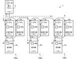
- FIG. 4 is a diagram for explaining communication when a duplicated address is defined in the air conditioning system according to the first embodiment.
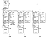
- FIG. 4 is a diagram for explaining communication when a duplicated address is defined in the air conditioning system according to the first embodiment.
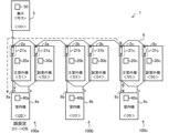
- FIG. 13 is a diagram for explaining communication when a repeater of a main outdoor unit that has detected address duplication is turned off.
- FIG. 13 is a diagram for explaining communication when the relay of the main outdoor unit in which a communication error is detected is set to an OFF state.
- FIG. 13 is a diagram for explaining communication when the repeater of the main outdoor unit in which address duplication has been detected is turned ON again.
- FIG. 13 is a diagram for explaining communication when the relay of the main outdoor unit in which a communication error has been detected is turned on again.
- FIG. 4 is a flowchart showing the operation of the air conditioning system according to the first embodiment. 4 is a diagram for explaining communication when a duplicated address is defined in the air conditioning system according to the first embodiment.
- FIG. 4 is a diagram for explaining communication when a duplicated address is defined in the air conditioning system according to the first embodiment.
- FIG. 4 is a diagram for explaining communication when a duplicated address is defined in the air conditioning system according to the first embodiment.
- FIG. 1 is a schematic configuration diagram showing an air conditioning system 1 according to a first embodiment.
- the air conditioning system 1 has air conditioners 100a to 100c and a central remote control 5.
- the air conditioning system 1 is placed in, for example, a data center, and controls the air conditioners 100a to 100c in an integrated manner to adjust the temperature of a space to be air-conditioned, such as a server room, to a temperature set by a user via the central remote control 5.
- any of the air conditioners 100a to 100c is made redundant in preparation for, for example, a failure or the like.
- the air conditioner 100a has a main outdoor unit 2a, a sub-outdoor unit 3a, and an indoor unit 4a.
- the main outdoor unit 2a has an outdoor control device 20a and a repeater 21a.
- the sub-outdoor unit 3a has an outdoor control device 30a and a repeater 31a.
- the indoor unit 4a has an indoor control device 40a.
- the central remote control 5 and the main outdoor unit 2a are connected by a centralized control line 6.
- the main outdoor unit 2a and the sub-outdoor unit 3a are connected by an outdoor signal line 7a.
- the main outdoor unit 2a and the indoor unit 4a are connected by an inside/outside signal line 8a.
- the air conditioner 100b has a main outdoor unit 2b, a sub outdoor unit 3b, and an indoor unit 4b.
- the main outdoor unit 2b has an outdoor control device 20b and a repeater 21b.
- the sub outdoor unit 3b has an outdoor control device 30b and a repeater 31b.
- the indoor unit 4b has an indoor control device 40b.
- the central remote control 5 and the main outdoor unit 2b are connected by a centralized control line 6.
- the main outdoor unit 2b and the sub outdoor unit 3b are connected by an outdoor signal line 7b.
- the main outdoor unit 2b and the indoor unit 4b are connected by an inside/outside signal line 8b.
- the air conditioner 100c has a main outdoor unit 2c, a sub outdoor unit 3c, and an indoor unit 4c.
- the main outdoor unit 2c has an outdoor control device 20c and a repeater 21c.
- the sub outdoor unit 3 has an outdoor control device 30c and a repeater 31c.
- the indoor unit 4c has an indoor control device 40c.
- the central remote control 5 and the main outdoor unit 2c are connected by a centralized control line 6.
- the main outdoor unit 2c and the sub outdoor unit 3c are connected by an outdoor signal line 7c.
- the main outdoor unit 2c and the indoor unit 4c are connected by an inside/outside signal line 8c.
- air conditioners 100a, 100b, or 100c correspond to the "first air conditioner” or “second air conditioner” in this disclosure.
- Main outdoor units 2a, 2b, or 2c correspond to the “first outdoor unit” or “second outdoor unit” and the "first main outdoor unit” or “second main outdoor unit” in this disclosure.
- Auxiliary outdoor units 3a, 3b, or 3c correspond to the "first auxiliary outdoor unit” or “second auxiliary outdoor unit” in this disclosure.
- Indoor units 4a, 4b, or 4c correspond to the “first indoor unit” or “second indoor unit” in this disclosure.
- Outdoor control devices 20a, 20b, or 20c correspond to the “first control device” or “second control device” in this disclosure.
- Repeaters 21a, 21b, or 21c correspond to the "first repeater” or “second repeater” in this disclosure.
- the exterior signal wires 7a, 7b, and 7c correspond to the "first exterior signal wire” and "second exterior signal wire” in this disclosure.
- the air conditioners 100a to 100c when the air conditioners 100a to 100c are not to be distinguished from one another, the subscripts "a" to “c” may be omitted and they may simply be referred to as the air conditioner 100. The same applies to each component of the air conditioner 100. However, even when the subscripts "a” to “c” are omitted, unless otherwise specified, this means that communication and control are performed between the same air conditioners 100, and does not indicate that communication and control are performed between different air conditioners 100.
- the number of air conditioners 100 may be two or four or more. Furthermore, when the main outdoor unit 2, the auxiliary outdoor unit 3, and the indoor unit 4 are not to be distinguished from one another, they may be referred to as units.
- the air conditioner 100 uses, for example, a refrigeration cycle as a heat source.
- the main outdoor unit 2 and the auxiliary outdoor unit 3 are installed in the space to be air-conditioned and function as heat source units, supplying hot or cold heat to the indoor unit 4.
- the auxiliary outdoor unit 3 plays an auxiliary role to the main outdoor unit 2 in supplying hot or cold heat.
- the indoor unit 4 is installed in the space to be air-conditioned and adjusts the temperature of the space to be air-conditioned by the hot or cold heat supplied from the main outdoor unit 2 and the auxiliary outdoor unit 3.
- the outdoor control device 20 of the main outdoor unit 2 communicates with the indoor control device 40 of the indoor unit 4 via the inside/outside signal line 8 and receives an operation status signal.
- the operation status signal is used to control the sending unit and is a signal that includes the operation status of each device of the sending unit, the measurement results of various sensors, and the communication status between the sending unit and other units.
- the outdoor control device 20 of the main outdoor unit 2 controls each device or fan (neither shown) of the refrigeration cycle of the main outdoor unit 2 based on the operation status signal and the measurement results of the refrigerant temperature sensor and air temperature sensor (not shown) of the main outdoor unit 2.
- the outdoor control device 20 also generates a control signal based on the operation status signal.
- the control signal is a signal for controlling each device of the destination unit.
- the outdoor control device 20 communicates with the indoor control device 40 of the indoor unit 4 via the inside/outside signal line 8 and transmits the control signal.
- the outdoor control device 20 communicates with the outdoor control device 30 of the auxiliary outdoor unit 3 via the outdoor signal line 7 and transmits control signals.
- the outdoor control device 20 receives an operation status signal from the outdoor control device 30.
- the outdoor control device 20 periodically transmits an operation status signal of the main outdoor unit 2 to the central control device 50 of the central remote control 5 described later.
- the operation status signal transmitted by the outdoor control device 20 to the central control device 50 may include an operation status signal of the sub outdoor unit 3.
- the outdoor control device 20 of the main outdoor unit 2 switches the connection state of the repeater 21 of the main outdoor unit 2.
- the repeater 21 of the main outdoor unit 2 is a device that relays the transmission of signals between the air conditioner 100 and the centralized remote control 5 via the centralized control line 6.
- the repeater 21 is, for example, a repeater that amplifies or shapes signals.
- the repeater 21 of the main outdoor unit 2 switches between an ON state that allows the connection between the air conditioner 100 and the centralized control line 6, and an OFF state that cuts off the connection between the air conditioner 100 and the centralized control line 6.
- the repeater 21 is in the ON state, communication is possible between the centralized control device 50 of the centralized remote control 5 and the outdoor control device 20 of the main outdoor unit 2 or the indoor control device 40 of the indoor unit 4.
- the auxiliary outdoor unit 3 has an outdoor control device 30 and a repeater 31.
- the outdoor control device 30 of the auxiliary outdoor unit 3 communicates with the outdoor control device 20 of the main outdoor unit 2 via the outdoor signal line 7 and receives control signals.
- the outdoor control device 30 of the auxiliary outdoor unit 3 controls each device of the refrigeration cycle or fans, etc. (none shown) of the auxiliary outdoor unit 3 based on the control signal.
- the outdoor control device 30 also periodically transmits an operating status signal to the outdoor control device 20.
- the configuration of the repeater 31 of the auxiliary outdoor unit 3 is the same as that of the repeater 21 of the main outdoor unit 2. However, the outdoor control device 30 of the auxiliary outdoor unit 3 always sets the repeater 31 of the auxiliary outdoor unit 3 to the OFF state.
- the indoor unit 4 has an indoor control device 40.
- the indoor control device 40 communicates with the centralized control device 50 of the central remote control 5 via the centralized control line 6, the repeater 21 of the main outdoor unit 2, and the internal/external signal line 8, and receives operation commands.
- the operation commands are information for controlling each device of the indoor unit 4.
- the operation commands are based on the contents set by the user via the central remote control 5, such as starting and stopping the operation of the indoor unit 4, the set temperature, set humidity, air volume, and air direction, as well as the operation status signals acquired by the centralized control device 50.
- the indoor control device 40 periodically transmits operation status signals to the centralized control device 50.
- the indoor control device 40 communicates with the outdoor control device 20 of the main outdoor unit 2 via the indoor/external signal line 8 and receives control signals.
- the indoor control device 40 transmits operation status signals to the outdoor control device 20.
- the indoor control device 40 controls the fan, expansion valve, air deflector, etc. (none of which are shown) of the indoor unit 4 based on the control signals and operation commands.
- the central remote control 5 has an operation display device (not shown) and a central control device 50.
- the operation display device is, for example, a touch panel, and accepts operation input from the user.
- the operation display device also displays the user's operation content, as well as the operating status of each unit based on the operation status signals from the main outdoor unit 2, the auxiliary outdoor unit 3, and the indoor unit 4.
- the centralized control device 50 generates operation commands based on the contents input by the user via the centralized remote control 5 and the information obtained from the operation status signal.
- the centralized control device 50 of the centralized remote control 5 communicates with the indoor control device 40 of the indoor unit 4 via the centralized control line 6 and the internal/external signal line 8, and transmits operation commands.
- the centralized control device 50 receives operation status signals from the outdoor control device 20 and the indoor control device 40. Note that it may also be possible to transmit operation commands to the indoor unit 4 via a remote control (not shown) possessed by the indoor unit 4, or by contact input from another device.
- Each unit is assigned an address.
- the address assigned to each unit is enclosed in ⁇ >.
- the address is registered by an administrator or maintenance personnel, and is information for identifying the unit.
- the address is required to be unique for each device in the air conditioning system 1.
- the operation command, control signal, and operating status signal include the address of the destination unit that is registered in advance in the control device of the sending unit.
- the operation command, control signal, and operating status signal are also assigned an address indicating the sending device.
- the unit that receives the operation command, control signal, and operating status signal transmits a response signal to the sending unit of the operation command, control signal, and operating status signal.
- the response signal is a signal indicating that the operation command, control signal, and operating status signal have been received.
- Normal communication includes communication transmitted and received within each air conditioner 100 and communication transmitted and received between each air conditioner 100 and the central remote control 5. Note that all communication paths are shown here, including the redundant air conditioners 100.
- FIG. 2 is a hardware configuration diagram showing an example of the configuration of the outdoor control device 20 according to the first embodiment.
- the outdoor control device 20 is configured by a processing circuit 61 as shown in FIG. 2.
- the processing circuit 61 corresponds to, for example, a single circuit, a composite circuit, a programmed processor, a parallel programmed processor, an ASIC (Application Specific Integrated Circuit), an FPGA (Field-Programmable Gate Array), or a combination of these.
- FIG. 3 is a hardware configuration diagram showing an example of the configuration of the outdoor control device 20 according to the first embodiment.
- the outdoor control device 20 is composed of a processor 62 such as a CPU and a memory 63, as shown in FIG. 3.
- Each function of the outdoor control device 20 is realized by the processor 62 and the memory 63.
- FIG. 3 shows that the processor 62 and the memory 63 are communicatively connected to each other via a bus 64.
- the function of the outdoor control device 20 is realized by software, firmware, or a combination of software and firmware.
- the software and firmware are written as programs and stored in the memory 63.
- the processor 62 realizes the functions of each means by reading and executing the programs stored in the memory 63.
- non-volatile semiconductor memory such as ROM (Read Only Memory), flash memory, EPROM (Erasable and Programmable ROM), and EEPROM (Electrically Erasable and Programmable ROM) may be used as memory 63.
- volatile semiconductor memory such as RAM (Random Access Memory) may be used as memory 63.
- removable recording media such as magnetic disks, flexible disks, optical disks, CDs (Compact Discs), MDs (Mini Discs), and DVDs (Digital Versatile Discs) may be used as memory 63.
- the outdoor control device 30 of the auxiliary outdoor unit 3, the indoor control device 40 of the indoor unit 4, and the central control device 50 of the central remote control 5 also have the same configuration.
- the repeater 21 is switched when the system of the air conditioners 100 of each system is established. Specifically, the outdoor control device 20 of the main outdoor unit 2 keeps the repeater 21 of the main outdoor unit 2 in the OFF state until the connection between the main outdoor unit 2 of the air conditioner 100 and the auxiliary outdoor unit 3 and indoor unit 4 is established, i.e., the system of the air conditioner 100 is established. This is to prevent the main outdoor unit 2 of the air conditioner 100 from being connected to the auxiliary outdoor unit 3 or indoor unit 4 of another air conditioner 100.
- the outdoor control device 20 of the main outdoor unit 2 switches the repeater 21 of the main outdoor unit 2 to the ON state.
- the indoor unit 4 receives an operation command from the central remote control 5 while the repeater 21 is in the ON state, it starts operation. After the indoor unit 4 starts operating, it operates based on the control signal received from the main outdoor unit 2. Even if the relay 21 is turned off after the indoor unit 4 starts operating, the indoor unit 4 can continue operating.
- a duplicate address definition occurs when an address that should be unique for each unit in the air conditioning system 1 is duplicated between two or more units due to a setting error.
- a duplicate address definition may occur when performing maintenance on the air conditioner 100, such as replacing the control device board.
- Figure 4 is a diagram for explaining communication when a duplicate address definition occurs in the air conditioning system 1 according to the first embodiment.
- Figure 5 is a diagram for explaining communication when a duplicate address definition occurs in the air conditioning system 1 according to the first embodiment.
- the main outdoor unit 2a of the air conditioner 100a is no longer able to communicate with the auxiliary outdoor unit 3a because an address different from the destination previously set in the outdoor control device 20a of the main outdoor unit 2a has been defined in the auxiliary outdoor unit 3a.
- Figure 5 also shows a new communication path created by the duplicate address definition. As shown in FIG. 5, communication across the air conditioner 100 system has occurred from the auxiliary outdoor unit 3c and indoor unit 4c of the air conditioner 100c to the auxiliary outdoor unit 3a of the air conditioner 100a. When duplicate address definition occurs in this way, the air conditioning system 1 cannot maintain a normal operating state.
- the outdoor control device 20 of the main outdoor unit 2 of the air conditioner 100 that detects the address overlap temporarily switches the repeater 21 of the main outdoor unit 2 to the OFF state. Specifically, the outdoor control device 20 of the main outdoor unit 2 detects the address overlap when it determines that a unit with the same address as itself is sending a signal during a period in which it is not sending a signal.
- the auxiliary outdoor unit 3a of the air conditioner 100a and the main outdoor unit 2c of the air conditioner 100c which have the same source address ⁇ 55>, send signals to the auxiliary outdoor unit 3c and the indoor unit 4c.
- FIG. 6 is a diagram for explaining communication when the repeater 21 of the main outdoor unit 2 that detected address duplication is turned off.
- the air conditioner 100c is disconnected from the centralized control line 6, cutting off communication across the systems and allowing the air conditioner 100c to continue operating.
- the outdoor control device 20 may also issue a report indicating that address duplication has been detected.
- the outdoor control device 20 of the main outdoor unit 2 of the air conditioner 100 in which the address has been set incorrectly temporarily switches the repeater 21 of the main outdoor unit 2 to an OFF state.
- the outdoor control device 20 of the main outdoor unit 2 detects a communication error if communication with the sub-outdoor unit 3 or the indoor unit 4 as the destination is not established.
- the outdoor control device 20 of the main outdoor unit 2 also detects a communication error if there is no communication from the sub-outdoor unit 3 or the indoor unit 4 for a specified time.
- the main outdoor unit 2a of the air conditioner 100a sends a control signal to the destination address ⁇ 52> pre-stored in the outdoor control device 20a, communication is not possible because the address ⁇ 52> does not exist.
- FIG. 7 is a diagram for explaining communication when the repeater 21 of the main outdoor unit 2 in which a communication error is detected is turned to the OFF state.
- the outdoor control device 20 may issue a report indicating that a communication error has been detected.
- the central control device 50 of the central remote control 5 cannot communicate with the air conditioner 100 because the repeater 21 has been switched to the OFF state.
- the central control device 50 may detect a communication error in the air conditioner 100 to which the operation command was sent.
- the central control device 50 may issue a notification indicating that a communication error has been detected in the air conditioner 100 to which the operation command was sent.
- the outdoor control device 20 of the main outdoor unit 2 switches the repeater 21 to the ON state.
- the first time is a time equal to or greater than the time required for the air conditioner 100 in which the address has been set incorrectly to detect a communication error and for the repeater 21 of the main outdoor unit 2 to be switched to the OFF state. If communication between the units constituting the air conditioner 100 is not established due to incorrect setting of the unit addresses, etc., communication is retried multiple times between the units, and if communication is not established in any case, it is determined that a communication error has occurred and the repeater 21 is set to the OFF state.
- FIG. 8 is a diagram for explaining communication when the repeater 21 of the main outdoor unit 2 in which an address overlap has been detected is turned ON again.
- the outdoor control device 20c of the main outdoor unit 2c of the air conditioner 100c turns ON the repeater 21c of the main outdoor unit 2c. This prevents a duplicate address definition from occurring again, and allows the air conditioner 100c to be connected to the centralized control line 6 to restore a normal connection state.
- the outdoor control device 20 of the main outdoor unit 2 switches the repeater 21 to the ON state.
- the incorrect address setting is corrected, for example, by maintenance personnel who have confirmed the alarm.
- communication between the main outdoor unit 2 and the auxiliary outdoor unit 3 or the indoor unit 4 within the air conditioner 100 is restored, and the outdoor control device 20 enters a state in which it does not detect a communication error.
- the second time period is equal to or longer than the time required for communication recovery within the air conditioner 100 after the address is corrected by the maintenance personnel, that is, the time required for the communication reconnection process.
- the second time period is set to avoid connection between the main outdoor unit 2 and the auxiliary outdoor unit 3 and the indoor unit 4 of the air conditioner 100 of another system.
- FIG. 9 is a diagram for explaining communication when the repeater 21 of the main outdoor unit 2 in which a communication error was detected is turned ON again. In the example of FIG.
- the address of the auxiliary outdoor unit 3a of the air conditioner 100a is corrected from ⁇ 55> to ⁇ 52>, which should have been set originally, so after the second time has elapsed, the outdoor control device 20a of the main outdoor unit 2a of the air conditioner 100a turns the repeater 21a of the main outdoor unit 2a ON. As a result, the air conditioner 100a is connected to the centralized control line 6, and the air conditioning system 1 is fully restored.
- FIG 10 is a flowchart showing the operation of the air conditioning system 1 according to the first embodiment.
- the operation of the outdoor control device 20 with respect to the control of the repeater 21 will be described using Figure 10.
- the outdoor control device 20 determines whether or not the address of the air conditioner 100 has been changed due to maintenance work or the like (step S1). If there has been no change in the address (step S1: NO), the outdoor control device 20 determines whether or not there has been an address overlap (step S2). If no address overlap is detected (step S2: NO), the outdoor control device 20 ends the process.
- step S2 If address duplication is detected (step S2: YES), the outdoor control device 20 issues an address duplication report (step S3) and switches the repeater 21 of the main outdoor unit 2 to the OFF state (step S4). After the first time has elapsed, the outdoor control device 20 switches the repeater 21 of the main outdoor unit 2 to the ON state (step S5). The outdoor control device 20 then determines whether or not there is address duplication (step S6). If address duplication is not detected, i.e., the address duplication has been resolved (step S6: NO), the outdoor control device 20 ends the process. If address duplication is detected, i.e., the address duplication has not been resolved (step S6: YES), the outdoor control device 20 repeats the processes of steps S4 and S5.
- step S7 determines whether a communication error has been detected. If a communication error has not been detected (step S7: NO), the outdoor control device 20 ends the process.
- step S7 If a communication error is detected (step S7: YES), the outdoor control device 20 issues a notification that a communication error has been detected (step S8) and switches the repeater 21 of the main outdoor unit 2 to the OFF state (step S9). At this time, the outdoor control device 20 accepts address correction from the maintenance personnel and determines whether the address has been corrected, that is, whether a communication error has been detected (step S10). If the address has not been corrected, that is, if a communication error has been detected (step S10: NO), the outdoor control device 20 ends the process.
- step S10 If the address has been corrected, that is, if a communication error has not been detected (step S10: YES), the outdoor control device 20 waits for communication recovery in the air conditioner 100 (step S11), and after the second time has elapsed, switches the repeater 21 of the main outdoor unit 2 to the ON state (step S12).
- the outdoor control device 20 repeatedly executes the above process at predetermined time intervals. The above process is also executed by each of the outdoor control devices 20a, 20b, and 20c.
- the outdoor control device 20 when the outdoor control device 20 detects an address overlap, it switches the repeater 21 to the OFF state. This resolves the address overlap in the first air conditioner, allowing the first air conditioner to continue operating. Therefore, the air conditioning system 1 can suppress a decrease in air conditioning capacity when the addresses of the air conditioner units are defined in a duplicated manner.
- the address of the auxiliary outdoor unit 3a of the air conditioner 100a which should be set to ⁇ 52>, is mistakenly set to ⁇ 55>, resulting in address duplication with the main outdoor unit 2c of the air conditioner 100c.
- address duplication can also be detected in other cases.
- a case will be described in which the address of the indoor unit 4 of one air conditioner 100 is mistakenly set to overlap with the address of the indoor unit 4 of another air conditioner 100.
- FIG. 11 is a diagram for explaining communication when an address is defined twice in the air conditioning system 1 according to the first embodiment. Note that FIG. 11 omits illustration of communication paths that are not related to the following description. As shown in FIG. 11, communication occurs between the main outdoor unit 2c of the air conditioner 100c and the indoor unit 4c of the air conditioner 100c, and communication occurs between the main outdoor unit 2c of the air conditioner 100c and the indoor unit 4a of the air conditioner 100a.
- the indoor control device 40c of the indoor unit 4c detects address duplication by determining that the indoor control device 40a of the indoor unit 4a, which has the same address as itself, is sending a signal during a period in which no signal is being sent to the outdoor control device 20c of the main outdoor unit 2c or the central control device 50 of the central remote control 5.
- the indoor control device 40c of the indoor unit 4c sends an address duplication error report to the outdoor control device 20c of the main outdoor unit 2c and the central control device 50 of the central remote control 5.
- the outdoor control device 20c of the main outdoor unit 2c turns the repeater 21 OFF when it receives an error notification of address duplication from the indoor control device 40c of the indoor unit 4c.
- the main outdoor unit 2a of the air conditioner 100a is unable to communicate with the indoor unit 4a because the indoor unit 4a is defined with an address ⁇ 05> that is different from the destination address ⁇ 01> predefined in the outdoor control device 20a of the main outdoor unit 2a. Therefore, the outdoor control device 20a of the main outdoor unit 2a of the air conditioner 100a detects the communication error and turns the repeater 21a OFF.
- FIG. 12 is a diagram for explaining communication when the address of the air conditioning system 1 according to the first embodiment is double-defined.
- the main outdoor unit 2a which controls the entire system of the air conditioner 100a, judges that the system has been changed when the address of the main outdoor unit 2a has been changed, turns off the repeater 21a of the outdoor control device 20a, and starts communication to check the connection status of the system of the air conditioner 100a.
- the main outdoor unit 2a performs an address scan and judges whether the system settings are correct based on the address at which the connection to the main outdoor unit 2a is detected.
- FIG. 12 is a diagram for explaining communication when the address of the air conditioning system 1 according to the first embodiment is double-defined.
- the main outdoor unit 2a detects the connection from the auxiliary outdoor unit 3a and the indoor unit 4a, but since the connection is not correct, it judges that the system settings of the air conditioner 100a are incorrect, and issues a system error while maintaining the repeater 21a in the OFF state. Because the main outdoor unit 2a of the air conditioner 100a keeps the repeater 21a in the OFF state, the central control device 50 of the central remote control 5 detects a communication error with the indoor control device 40a of the indoor unit 4a. The system error of the air conditioner 100a is resolved by correcting the address of the main outdoor unit 2a of the air conditioner 100a to ⁇ 51> and turning the power back on. In this case, the main outdoor unit 2c of the air conditioner 100c does not detect the address overlap.
- 1 air conditioning system 2, 2a, 2b, 2c main outdoor unit, 3, 3a, 3b, 3c auxiliary outdoor unit, 4, 4a, 4b, 4c indoor unit, 5 central remote control, 6 central control line, 7, 7a, 7b, 7c outdoor signal line, 8, 8a, 8b, 8c inside and outside signal line, 20, 20a, 20b, 20c, 30, 30a, 30b, 30c outdoor control device, 21, 21a, 21b, 21c, 31, 31a, 31b, 31c repeater, 40, 40a, 40b, 40c indoor control device, 50 central control device, 61 processing circuit, 62 processor, 63 memory, 64 bus, 100, 100a, 100b, 100c air conditioner.
Landscapes
- Engineering & Computer Science (AREA)
- Chemical & Material Sciences (AREA)
- Combustion & Propulsion (AREA)
- Mechanical Engineering (AREA)
- General Engineering & Computer Science (AREA)
- Air Conditioning Control Device (AREA)
Abstract
空調システムは、第1室外機及び第1室内機を有する第1空気調和機と、第2室外機及び第2室内機を有し、集中管理線によって第1空気調和機と接続された第2空気調和機と、を備え、第1室外機は、第1空気調和機と集中管理線との接続を許容するON状態と、第1空気調和機と集中管理線との接続を遮断するOFF状態と、を切り替える第1中継器と、第1中継器を制御する第1制御装置と、を有し、第1制御装置は、第1室外機又は第1室内機のアドレスが、誤設定された第2室外機又は第2室内機のアドレスに重複する、アドレス被重複を検出した場合、第1中継器をOFF状態に切り替える。
Description
本開示は、複数の空気調和機を備える空調システムに関する。
従来、複数の空気調和機を備えた空調システムにおいて、空気調和機の通信に何らかの障害が生じた際に、他の空気調和機に波及することを抑制するため、障害の発生した空気調和機を空調システムから切り離す方法が知られている(例えば、特許文献1)。これにより、特許文献1の空調システムでは、正常な通信路での通信状態を維持し、運転を継続させている。
例えば、データセンターに設置される空調システムでは、継続して稼働することが非常に重要とされている。このため、従来、データセンターに設置される空調システムでは、空気調和機に障害が生じた場合であっても、システム全体が正常に機能し続けることができるように、予備の空気調和機を配置して運用していることがある。つまり、空気調和機が故障した場合でもシステム全体が維持できるように、空気調和機を、必要な台数Nに対して、N+1に冗長化している。
このような予備の空気調和機を備えた空調システムにおいて、ある空気調和機の保守を行う際には、予備の空気調和機を起動させて運転を行うことがある。しかしながらこの際に、予備の空気調和機のアドレスを、継続して稼働させる他の空気調和機のアドレスと誤って重複させてしまった場合、継続して稼働させる空気調和機の動作に異常をさせてしまい、空調システムの運用に支障をきたす虞がある。このとき、空調システムでは、アドレスの誤設定がされた空気調和機と、アドレスが重複された空気調和機とが存在するところ、特許文献1の空調システムのように、障害の発生した空気調和機を空調システムから切り離す場合、アドレスの誤設定がされた空気調和機と、アドレスが重複された空気調和機との両方が空調システムから切り離されてしまう。よって、特許文献1の空調システムによれば、必要な空調能力を維持することができないことがある。
本開示は、上記のような課題を解決するためになされたもので、空気調和機のユニットのアドレスが重複して定義された場合において、空調システムの空調能力の低下を抑制することを目的とするものである。
本開示に係る空調システムは、第1室外機及び第1室内機を有する第1空気調和機と、第2室外機及び第2室内機を有し、集中管理線によって第1空気調和機と接続された第2空気調和機と、を備え、第1室外機は、第1空気調和機と集中管理線との接続を許容するON状態と、第1空気調和機と集中管理線との接続を遮断するOFF状態と、を切り替える第1中継器と、第1中継器を制御する第1制御装置と、を有し、第1制御装置は、第1室外機又は第1室内機のアドレスが、誤設定された第2室外機又は第2室内機のアドレスに重複する、アドレス被重複を検出した場合、第1中継器をOFF状態に切り替える。
本開示によれば、第1制御装置は、アドレス被重複を検出した場合、中継器をOFF状態に切り替える。これにより、第1空気調和機ではアドレス被重複が解消されるため、第1空気調和機は、運転を継続することができる。このため、空調システムは、空気調和機のユニットのアドレスが重複して定義された場合において、空調能力の低下を抑制することができる。
実施の形態1.
図1は、実施の形態1に係る空調システム1を示す概略構成図である。図1に示すように、空調システム1は、空気調和機100a~100c、及び集中リモコン5を有する。空調システム1は、例えばデータセンターに配置され、空気調和機100a~100cを統合的に制御することで、サーバルーム等の空調対象空間の温度を、ユーザが集中リモコン5を介して設定した温度に調整するものである。また、空気調和機100a~100cの何れかは、例えば障害等に備えて冗長化されたものである。
図1は、実施の形態1に係る空調システム1を示す概略構成図である。図1に示すように、空調システム1は、空気調和機100a~100c、及び集中リモコン5を有する。空調システム1は、例えばデータセンターに配置され、空気調和機100a~100cを統合的に制御することで、サーバルーム等の空調対象空間の温度を、ユーザが集中リモコン5を介して設定した温度に調整するものである。また、空気調和機100a~100cの何れかは、例えば障害等に備えて冗長化されたものである。
空気調和機100aは、主室外機2a、副室外機3a及び室内機4aを有している。主室外機2aは、室外制御装置20a及び中継器21aを有する。副室外機3aは、室外制御装置30a及び中継器31aを有する。室内機4aは、室内制御装置40aを有する。集中リモコン5と主室外機2aとは、集中管理線6によって接続される。主室外機2aと副室外機3aとは室外信号線7aによって接続される。主室外機2aと室内機4aとは、内外信号線8aによって接続される。
同様に、空気調和機100bは、主室外機2b、副室外機3b及び室内機4bを有している。主室外機2bは、室外制御装置20b及び中継器21bを有する。副室外機3bは、室外制御装置30b及び中継器31bを有する。室内機4bは、室内制御装置40bを有する。集中リモコン5と主室外機2bとは、集中管理線6によって接続される。主室外機2bと副室外機3bとは室外信号線7bによって接続される。主室外機2bと室内機4bとは、内外信号線8bによって接続される。
更に同様に、空気調和機100cは、主室外機2c、副室外機3c及び室内機4cを有している。主室外機2cは、室外制御装置20c及び中継器21cを有する。副室外機3は、室外制御装置30c及び中継器31cを有する。室内機4cは、室内制御装置40cを有する。集中リモコン5と主室外機2cとは、集中管理線6によって接続される。主室外機2cと副室外機3cとは室外信号線7cによって接続される。主室外機2cと室内機4cとは、内外信号線8cによって接続される。
なお、空気調和機100a、100b又は100cは、本開示の「第1空気調和機」又は「第2空気調和機」に相当する。主室外機2a、2b又は2cは、本開示の「第1室外機」又は「第2室外機」、及び「第1主室外機」又は「第2主室外機」に相当する。副室外機3a、3b又は3cは、本開示の「第1副室外機」又は「第2副室外機」に相当する。室内機4a、4b又は4cは、本開示の「第1室内機」又は「第2室内機」に相当する。室外制御装置20a、20b又は20cは、本開示の「第1制御装置」又は「第2制御装置」に相当する。中継器21a、21b又は21cは、本開示の「第1中継器」又は「第2中継器」に相当する。室外信号線7a、7b又は7cは、本開示の「第1室外信号線」又は「第2室外信号線」に相当する。
以下の説明において空気調和機100a~100cを区別しない場合、添字「a」~「c」の添字を省略して単に空気調和機100と称することがある。空気調和機100が有する各構成についても同様である。ただし、添字「a」~「c」の添字を省略して説明している場合であっても、特に説明していない限りは同一の空気調和機100間で通信及び制御が行われることを意味しており、異なる空気調和機100の間で通信及び制御が行われることを示すものではない。なお、空気調和機100の台数は、2台又は4台以上であってもよい。また、主室外機2、副室外機3、及び室内機4を区別しない場合、ユニットと称することがある。
空気調和機100は、熱源として例えば冷凍サイクルを利用している。主室外機2及び副室外機3は、空調対象空間に設けられて熱源機として機能し、室内機4に温熱又は冷熱を供給する。なお、副室外機3は、温熱又は冷熱の供給にあたって、主室外機2の補助的な役割を有する。室内機4は、空調対象空間に設けられ、主室外機2及び副室外機3から供給された温熱又は冷熱によって空調対象空間の温度を調整する。
主室外機2の室外制御装置20は、室内機4の室内制御装置40と内外信号線8を介して通信を行い、動作状態信号を受信する。動作状態信号は、送信元のユニットの制御に用いられるものであって、送信元のユニットが有する各機器の動作状態、及び種々のセンサの測定結果、及び送信元のユニットと他のユニットとの通信状況等を含んだ信号である。主室外機2の室外制御装置20は、動作状態信号、並びに主室外機2が有する冷媒温度センサ及び空気温度センサ(図示せず)等の測定結果に基づいて、主室外機2が有する冷凍サイクルの各機器又はファン等(何れも図示せず)を制御する。また、室外制御装置20は、動作状態信号に基づき、制御信号を生成する。制御信号は、送信先のユニットが有する各機器を制御するための信号である。室外制御装置20は、室内機4の室内制御装置40と内外信号線8を介して通信を行い、制御信号を送信する。
室外制御装置20は、副室外機3の室外制御装置30と室外信号線7を介して通信を行い、制御信号を送信する。室外制御装置20は、室外制御装置30から動作状態信号を受信する。
室外制御装置20は、後述する集中リモコン5の集中制御装置50に主室外機2の動作状態信号を定期的に送信する。なお、室外制御装置20が、集中制御装置50に送信する動作状態信号は、副室外機3の動作状態信号を含んだものであってもよい。
主室外機2の室外制御装置20は、主室外機2の中継器21の接続状態を切り替える。主室外機2の中継器21は、空気調和機100と集中管理線6を介した集中リモコン5との信号の伝送を中継する装置である。中継器21は、例えば信号の増幅又は整形等を行うリピータである。主室外機2の中継器21は、空気調和機100と集中管理線6との接続を許容するON状態と、空気調和機100と集中管理線6との接続を遮断するOFF状態とを切り替える。中継器21がON状態のとき、集中リモコン5の集中制御装置50と、主室外機2の室外制御装置20又は室内機4の室内制御装置40とは、通信が可能である。一方で、中継器21がOFF状態のとき、集中リモコン5の集中制御装置50と、主室外機2の室外制御装置20及び室内機4の室内制御装置40とは、通信が不可能である。主室外機2の中継器21を切り替える条件については、後述する。
副室外機3は、室外制御装置30及び中継器31を有する。副室外機3の室外制御装置30は、主室外機2の室外制御装置20と室外信号線7を介して通信を行い、制御信号を受信する。そして、副室外機3の室外制御装置30は、制御信号に基づいて、副室外機3が有する冷凍サイクルの各機器又はファン等(何れも図示せず)を制御する。また、室外制御装置30は、室外制御装置20に動作状態信号を定期的に送信する。
副室外機3の中継器31の構成は、主室外機2の中継器21と同様である。ただし、副室外機3の室外制御装置30は、副室外機3の中継器31を常にOFF状態に設定する。
室内機4は、室内制御装置40を有する。室内制御装置40は、集中管理線6、主室外機2の中継器21、及び内外信号線8を介して集中リモコン5の集中制御装置50と通信を行い、運転指令を受信する。運転指令は、室内機4が有する各機器を制御するための情報である。運転指令は、室内機4の運転の開始及び停止、設定温度、設定湿度、風量、及び風向などのユーザが集中リモコン5を介して設定した内容、並びに集中制御装置50が取得した動作状態信号に基づくものである。室内制御装置40は、集中制御装置50に動作状態信号を定期的に送信する。
室内制御装置40は、内外信号線8を介して主室外機2の室外制御装置20と通信を行い、制御信号を受信する。室内制御装置40は、室外制御装置20に動作状態信号を送信する。室内制御装置40は、制御信号、及び運転指令に基づいて、室内機4が有するファン、膨張弁、又は風向板等(何れも図示せず)を制御する。
集中リモコン5は、操作表示装置(図示せず)及び集中制御装置50を有する。操作表示装置は、例えばタッチパネル等であって、ユーザからの操作入力を受け付ける。また、操作表示装置は、ユーザの操作内容、並びに主室外機2、副室外機3及び室内機4から動作状態信号に基づく各ユニットの運転状態等を表示するものである。
集中制御装置50は、ユーザが集中リモコン5を介して入力した内容と、動作状態信号から取得した情報とに基づいて運転指令を生成する。集中リモコン5の集中制御装置50は、室内機4の室内制御装置40と集中管理線6及び内外信号線8を介して通信を行い、運転指令を送信する。集中制御装置50は、室外制御装置20及び室内制御装置40から動作状態信号を受信する。なお、室内機4が有するリモコン(図示せず)を介して、あるいは他の機器からの接点入力によって、室内機4に運転指令を送信できるようにしてもよい。
各ユニットにはアドレスが設定されている。図1では、各ユニットに設定されたアドレスを<>で囲んで示している。アドレスは、管理者又はメンテナンス要員等によって登録されたものであって、ユニットを識別するための情報である。アドレスは、空調システム1内の装置ごとにユニークになることが求められる。運転指令、制御信号及び動作状態信号には、送信元のユニットの制御装置に予め登録されている送信先のユニットのアドレスが含まれている。また、運転指令、制御信号及び動作状態信号には、送信元の機器を示すアドレスが付加されている。加えて、運転指令、制御信号及び動作状態信号を受信したユニットは、運転指令、制御信号及び動作状態信号の送信元のユニットに応答信号を送信する。応答信号は、運転指令、制御信号及び動作状態信号を受信した旨を示す信号である。図1では、各装置にユニークなアドレスが設定された場合の正常な通信経路が破線矢印で示されている。正常な通信としては、それぞれの空気調和機100内で送受信されるものと、それぞれの空気調和機100と集中リモコン5とで送受信されるものとがある。なお、ここでは冗長化された空気調和機100も含めて全ての通信経路を示している。
ここで、室外制御装置20のハードウェアの一例を説明する。図2は、実施の形態1に係る室外制御装置20の一構成例を示すハードウェア構成図である。室外制御装置20の各種機能がハードウェアで実行される場合、室外制御装置20は、図2に示すように、処理回路61で構成される。処理回路61は、例えば、単一回路、複合回路、プログラム化したプロセッサ、並列プログラム化したプロセッサ、ASIC(Application Specific Integrated Circuit)、FPGA(Field-Programmable Gate Array)、または、これらを組み合わせたものに該当する。
また、室外制御装置20の別のハードウェアの一例を説明する。図3は、実施の形態1に係る室外制御装置20の一構成例を示すハードウェア構成図である。室外制御装置20の各種機能がソフトウェアで実行される場合、室外制御装置20は、図3に示すように、CPU等のプロセッサ62およびメモリ63で構成される。室外制御装置20の各機能は、プロセッサ62およびメモリ63により実現される。図3は、プロセッサ62およびメモリ63が互いにバス64を介して通信可能に接続されることを示している。各機能がソフトウェアで実行される場合、室外制御装置20の機能は、ソフトウェア、ファームウェア、またはソフトウェアとファームウェアとの組み合わせにより実現される。ソフトウェアおよびファームウェアは、プログラムとして記述され、メモリ63に格納される。プロセッサ62は、メモリ63に記憶されたプログラムを読み出して実行することにより、各手段の機能を実現する。
メモリ63として、例えば、ROM(Read Only Memory)、フラッシュメモリ、EPROM(Erasable and Programmable ROM)およびEEPROM(Electrically Erasable and Programmable ROM)等の不揮発性の半導体メモリが用いられる。また、メモリ63として、RAM(Random Access Memory)の揮発性の半導体メモリが用いられてもよい。さらに、メモリ63として、磁気ディスク、フレキシブルディスク、光ディスク、CD(Compact Disc)、MD(Mini Disc)およびDVD(Digital Versatile Disc)等の着脱可能な記録媒体が用いられてもよい。なお、副室外機3の室外制御装置30、室内機4の室内制御装置40、及び集中リモコン5の集中制御装置50も同様の構成である。
次に、中継器21を切り替える条件について説明する。先ず、各系統の空気調和機100のシステムの確立時において中継器21を切り替える。具体的に、主室外機2の室外制御装置20は、空気調和機100の主室外機2と、副室外機3及び室内機4との接続、即ち空気調和機100のシステムが確立されるまで、主室外機2の中継器21をOFF状態にしている。これは、空気調和機100の主室外機2と、他の空気調和機100の副室外機3又は室内機4との接続が行われることを回避するためである。主室外機2の室外制御装置20は、空気調和機100の主室外機2と、副室外機3及び室内機4との接続が確立されると、主室外機2の中継器21をON状態に切り替える。室内機4は、中継器21がON状態中に集中リモコン5から運転指令を受信すると、運転を開始する。室内機4は、運転を開始してからは、主室外機2から受信した制御信号に基づいて動作を行う。室内機4が運転を開始した後に、中継器21がOFF状態になった場合であっても、室内機4は運転を継続することができる。
次に、アドレス二重定義が生じた際の中継器21を切り替える条件について説明する。アドレス二重定義は、上述のように本来空調システム1内のユニットごとにユニークな識別情報となるべきアドレスが、設定の誤りによって2つ以上のユニットで重複することである。アドレス二重定義は、例えば、制御装置の基板の交換等、空気調和機100の保守を行う際に生じることがある。図4は、実施の形態1に係る空調システム1のアドレス二重定義時の通信を説明するための図である。図5は、実施の形態1に係る空調システム1のアドレス二重定義時の通信を説明するための図である。図4及び図5に示す例では、空気調和機100aの副室外機3aのアドレスを、本来<52>とすべきところ、誤って<55>と設定してしまったことで、空気調和機100cの主室外機2cとアドレスが重複してしまったことを示している。
アドレス二重定義が生じている場合、アドレスの変更時に誤設定をした空気調和機100と、正しいアドレスが設定されているものの誤設定が生じている空気調和機100とアドレスが重複している空気調和機100とが存在する。前者のアドレスの誤設定は、誤設定をした空気調和機100では通信エラーとして検出される。後者の空気調和機100において検出される事象を、アドレス被重複と称する。なお、通信エラー及びアドレス被重複は、これらを検出するための設けられた特別な運転モード中に検出されるのではなく、日常的に行われている定期的な通信の中で検出される。図4は、図1で示した正常な通信経路の変化を示している。図4に示すように、空気調和機100aの主室外機2aは、主室外機2aの室外制御装置20aに予め定められている送信先と異なるアドレスが、副室外機3aに定義されたことで、副室外機3aとの間での通信が成立しなくなっている。また、図5は、アドレス二重定義によって新たに生じた通信経路を示している。図5に示すように、空気調和機100cの副室外機3c及び室内機4cから、空気調和機100aの副室外機3aへの空気調和機100の系統を跨いだ通信が発生してしまっている。このように、アドレス二重定義が生じた場合には、空調システム1は、正常な運転状態を維持することができない。
そこで、アドレス被重複を検出した空気調和機100の主室外機2の室外制御装置20は、主室外機2の中継器21を一時的にOFF状態にする。具体的に、主室外機2の室外制御装置20は、自身が信号を送信していない期間に、自身と同一のアドレスのユニットが信号を送信していると判定した場合にアドレス被重複を検出する。図4及び図5の例では、同一の送信元アドレス<55>を有する空気調和機100aの副室外機3a及び空気調和機100cの主室外機2cが副室外機3c及び室内機4cへ信号を送信している。これにより、空気調和機100cの主室外機2cは、空気調和機100cでのアドレス<55>についてのアドレス被重複を検出する。そして、図6に示すように、空気調和機100cの主室外機2cは、主室外機2cの中継器21cをOFF状態にする。図6は、アドレス被重複を検出した主室外機2の中継器21をOFF状態にした時の通信を説明するための図である。これにより、空気調和機100cは、集中管理線6から切り離されることで、系統間を跨いだ通信が遮断され、空気調和機100cは運転を継続することができる。なお、室外制御装置20は、アドレス被重複が検出されたことを示す発報を行ってもよい。
一方で、アドレスの誤設定が生じている空気調和機100の主室外機2の室外制御装置20は、主室外機2の中継器21を一時的にOFF状態にする。主室外機2の室外制御装置20は、副室外機3又は室内機4を送信先とした通信が成立しない場合、通信エラーを検出する。また、主室外機2の室外制御装置20は、所定の時間、副室外機3又は室内機4からの通信が無い場合、通信エラーを検出する。図6の例では、空気調和機100aの主室外機2aは、室外制御装置20aに予め記憶されている送信先のアドレス<52>あてに制御信号を送ったところ、アドレス<52>が存在しないことから通信ができない。このため、空気調和機100aの主室外機2aは、副室外機3aとの間で通信エラーを検出する。このとき、空気調和機100aの主室外機2aの室外制御装置20aは、図7に示すように、主室外機2aの中継器21aをOFF状態にする。図7は、通信エラーを検出した主室外機2の中継器21をOFF状態にした時の通信を説明するための図である。これにより、空気調和機100aは、集中管理線6から切り離されることで、アドレス被重複が検出されている空気調和機100cが集中管理線6に再接続した場合にも、集中管理線6に接続された空気調和機100aとの間でアドレスの二重定義が発生しない。なお、室外制御装置20は、通信エラーが検出されたことを示す発報を行ってもよい。また、集中リモコン5の集中制御装置50は、中継器21がOFF状態に切り替わったことで、空気調和機100との通信が成立しなくなる。このとき、集中制御装置50は、運転指令の送信先としていた空気調和機100において通信エラーを検出するようにしてもよい。更に、集中制御装置50は、運転指令の送信先としていた空気調和機100において通信エラーが検出されたことを示す発報を行ってもよい。
アドレス被重複が検出されたことで中継器21をOFF状態に切り替えてから第1の時間が経過しても、アドレス被重複を検出しない場合、主室外機2の室外制御装置20は、中継器21をON状態に切り替える。第1の時間は、アドレスの誤設定が生じている空気調和機100で通信エラーの検出、及び主室外機2の中継器21のOFF状態への切り替えに要する時間以上の時間である。ユニットのアドレスの誤設定等により、空気調和機100を構成するユニット間での通信が成立しない場合、ユニット間で通信のリトライを複数回行い、いずれも通信が成立しないときに通信エラーと判定され、中継器21がOFF状態に設定される。このように、通信エラーの原因となるアドレスの誤設定から、アドレスの誤設定が生じた空気調和機100の中継器21がOFF状態になるまでには時間を要するので、この時間はアドレス被重複が生じた中継器21を再接続しないようにしている。つまり、第1の時間は、アドレス被重複が検出された空気調和機100と、通信エラーが検出された空気調和機100が同時に集中管理線6に接続することを回避するために設定されている。図8は、アドレスの被重複を検出した主室外機2の中継器21を再度ON状態にした時の通信を説明するための図である。図8の例では、空気調和機100cの主室外機2cの室外制御装置20cは、主室外機2cの中継器21cをON状態にしている。これにより、再度アドレス二重定義となることを回避した上で、空気調和機100cを集中管理線6に接続させて、正常な接続状態に復旧させることができる。
通信エラーが検出されたことで中継器21をOFF状態に切り替えた後に第2の時間、空気調和機100の主室外機2と副室外機3との間、又は主室外機2と室内機4との間で通信エラーを検出しない場合、主室外機2の室外制御装置20は、中継器21をON状態に切り替える。アドレスの誤設定は、例えば発報を確認したメンテナンス要員によって修正される。これにより、空気調和機100内での主室外機2と、副室外機3又は室内機4との通信が復旧するため、室外制御装置20は、通信エラーを検出しない状態となる。第2の時間は、メンテナンス要員によるアドレスの修正後における空気調和機100内での通信の復旧、つまり通信の再接続処理に要する時間以上の時間である。第2の時間は、主室外機2と、他系統の空気調和機100の副室外機3及び室内機4との接続が行われることを回避するために設定されている。図9は、通信エラーを検出した主室外機2の中継器21を再度ON状態にした時の通信を説明するための図である。図9の例では、空気調和機100aの副室外機3aのアドレスが<55>から本来設定すべき<52>に修正されたため、第2の時間経過後、空気調和機100aの主室外機2aの室外制御装置20aは、主室外機2aの中継器21aをON状態にする。これにより、空気調和機100aが集中管理線6に接続され、空調システム1が完全に復旧することとなる。
図10は、実施の形態1に係る空調システム1の動作を示すフローチャートである。図10を用いて、中継器21の制御に関する室外制御装置20の動作について説明する。先ず、室外制御装置20は、空気調和機100において保守作業等によるアドレスの変更があったか否かを判定する(ステップS1)。アドレスの変更がなかった場合(ステップS1:NO)、室外制御装置20は、アドレス被重複があったか否かを判定する(ステップS2)。アドレス被重複が検出されない場合(ステップS2:NO)、室外制御装置20は処理を終了する。
アドレス被重複が検出された場合(ステップS2:YES)、室外制御装置20は、アドレス被重複を発報し(ステップS3)、主室外機2の中継器21をOFF状態に切り替える(ステップS4)。第1の時間経過後、室外制御装置20は、主室外機2の中継器21をON状態に切り替える(ステップS5)。そして、室外制御装置20は、アドレス被重複があるか否かを判定する(ステップS6)。アドレス被重複が検出されない、即ちアドレス被重複が解消している場合(ステップS6:NO)、室外制御装置20は、処理を終了する。アドレス被重複が検出される、即ちアドレス被重複が解消していない場合(ステップS6:YES)、室外制御装置20は、ステップS4及びS5の処理を繰り返す。
アドレスの変更があった場合(ステップS1:YES)、室外制御装置20は、通信エラーが検出されたか否かを判定する(ステップS7)。通信エラーが検出されない場合(ステップS7:NO)、室外制御装置20は、処理を終了する。
通信エラーが検出された場合(ステップS7:YES)、室外制御装置20は、通信エラーが検出されたことを発報し(ステップS8)、主室外機2の中継器21をOFF状態に切り替える(ステップS9)。このとき、メンテナンス要員からアドレスの修正を受け付け、室外制御装置20は、アドレスの修正があったか否か、即ち通信エラーの検出が有無を判定する(ステップS10)。アドレスの修正が無かった、つまり通信エラーが検出されている場合(ステップS10:NO)、室外制御装置20は、処理を終了する。アドレスの修正があった、つまり通信エラーが検出されない場合(ステップS10:YES)、室外制御装置20は、空気調和機100での通信復旧を待機し(ステップS11)、第2の時間経過後、主室外機2の中継器21をON状態に切り替える(ステップS12)。室外制御装置20は、上記の処理を所定の時間ごとに繰り返し実行する。また上記の処理は、室外制御装置20a、20b及び20cのそれぞれで実行される。
なお、ある空気調和機100においてアドレス被重複が検出されるケースでは、他の空気調和機100において通信エラーが検出される。このとき、実際にはアドレス被重複を検出する時間の方が、通信エラーを検出する時間よりも十分早い。したがって、空調システム1内でアドレス被重複が検出されていない状態で通信エラーが検出されて、ステップS7~S12の制御が行われることはない。
また、同一の空気調和機100内でアドレスが二重定義される場合、同一の空気調和機100においてアドレス被重複及び通信エラーの両方が検出される。この場合、アドレス被重複及び通信エラーが検出されている空気調和機100の主室外機2の中継器21がOFF状態に切り替えられ、集中管理線6から切り離される。
本実施の形態1によれば、室外制御装置20は、アドレス被重複を検出した場合、中継器21をOFF状態に切り替える。これにより、第1空気調和機ではアドレス被重複が解消されるため、第1空気調和機は、運転を継続することができる。このため、空調システム1は、空気調和機のユニットのアドレスが重複して定義された場合において、空調能力の低下を抑制することができる。
なお、図4及び図5に示す例では、空気調和機100aの副室外機3aのアドレスを、本来<52>とすべきところ、誤って<55>と設定してしまったことで、空気調和機100cの主室外機2cとアドレスが重複してしまった場合を例として示したが、他の場合にもアドレス被重複を検出することができる。そこで、ある空気調和機100の室内機4のアドレスが、誤って設定されたことで、他の空気調和機100の室内機4のアドレスと重複してしまった場合について説明する。例えば、空気調和機100aの室内機4aのアドレスを、本来<01>とすべきところ、誤って<05>と設定してしまったことで、空気調和機100cの室内機4cとアドレスが重複してしまった場合を例として取り上げる。
この例について図11を用いて説明する。図11は、実施の形態1に係る空調システム1のアドレス二重定義時の通信を説明するための図である。なお、図11では、下記の説明に関係しない通信経路の図示を省略している。図11に示すように、空気調和機100cの主室外機2cと空気調和機100cの室内機4cとの通信と、空気調和機100cの主室外機2cと空気調和機100aの室内機4aとの通信とが発生している。つまり、室内機4cの室内制御装置40cは、主室外機2cの室外制御装置20c又は集中リモコン5の集中制御装置50に対して信号を送信していない期間に、自身と同一のアドレスを持つ室内機4aの室内制御装置40aが信号を送信していると判定することで、アドレス被重複を検出する。室内機4cの室内制御装置40cは、アドレス被重複のエラー通報を主室外機2cの室外制御装置20c及び集中リモコン5の集中制御装置50に送信する。主室外機2cの室外制御装置20cは、室内機4cの室内制御装置40cからアドレス重複のエラー通報を受信することで、中継器21をOFF状態にする。また、空気調和機100aの主室外機2aは、主室外機2aの室外制御装置20aに予め定められている送信先のアドレス<01>と異なるアドレス<05>が、室内機4aに定義されたことで、室内機4aとの間での通信ができなくなっている。このため、空気調和機100aの主室外機2aの室外制御装置20aは、通信エラーを検出して、中継器21aをOFF状態にする。
また、ある空気調和機100の主室外機2のアドレスが、誤って設定されたことで、他の空気調和機100の主室外機2のアドレスと重複してしまった場合について説明する。例えば、空気調和機100aの主室外機2aのアドレスを、本来<51>とすべきところ、誤って<55>と設定してしまったことで、空気調和機100cの主室外機2cとアドレスが重複してしまった場合を例として取り上げる。
この例について図12を用いて説明する。図12は、実施の形態1に係る空調システム1のアドレス二重定義時の通信を説明するための図である。図12に示すように、空気調和機100aのシステム全体を統括する主室外機2aは、主室外機2aのアドレスに変更があった場合、システムの変更と判断し、室外制御装置20aの中継器21aをOFF状態とした上で、空気調和機100aのシステムの接続状態を確認するための通信を開始する。具体的に、主室外機2aは、アドレススキャンを行い、主室外機2aへの接続が検知されたアドレスによってシステムの設定の正誤を判定する。図12の例では、主室外機2aは、副室外機3a及び室内機4aからの接続を検知するものの、正しい接続関係ではないため、空気調和機100aのシステムの設定が誤っていると判定し、中継器21aをOFF状態に維持したままシステムエラーを発報する。空気調和機100aの主室外機2aが中継器21aをOFF状態に維持しているため、集中リモコン5の集中制御装置50は、室内機4aの室内制御装置40aとの間で通信エラーを検出する。空気調和機100aのシステムエラーは、空気調和機100aの主室外機2aのアドレスを<51>に是正し、電源を再投入することで解消される。なお、この場合、空気調和機100cの主室外機2cは、アドレス被重複を検出しない。
1 空調システム、2、2a、2b、2c 主室外機、3、3a、3b、3c 副室外機、4、4a、4b、4c 室内機、5 集中リモコン、6 集中管理線、7、7a、7b、7c 室外信号線、8、8a、8b、8c 内外信号線、20、20a、20b、20c、30、30a、30b、30c 室外制御装置、21、21a、21b、21c、31、31a、31b、31c 中継器、40、40a、40b、40c 室内制御装置、50 集中制御装置、61 処理回路、62 プロセッサ、63 メモリ、64 バス、100、100a、100b、100c 空気調和機。
Claims (10)
- 第1室外機及び第1室内機を有する第1空気調和機と、
第2室外機及び第2室内機を有し、集中管理線によって前記第1空気調和機と接続された第2空気調和機と、を備え、
前記第1室外機は、
前記第1空気調和機と前記集中管理線との接続を許容するON状態と、前記第1空気調和機と前記集中管理線との接続を遮断するOFF状態と、を切り替える第1中継器と、
前記第1中継器を制御する第1制御装置と、を有し、
前記第1制御装置は、
前記第1室外機又は前記第1室内機のアドレスが、誤設定された前記第2室外機又は前記第2室内機のアドレスに重複する、アドレス被重複を検出した場合、前記第1中継器を前記OFF状態に切り替える
空調システム。 - 前記第1制御装置は、前記第1室外機又は前記第1室内機が自身と同一のアドレスの前記第2室外機又は前記第2室内機が信号を送信していると判定した場合、前記アドレス被重複を検出する
請求項1に記載の空調システム。 - 前記第1制御装置は、前記第1中継器を前記OFF状態に切り替えてから第1の時間経過後、前記第1中継器を前記ON状態に切り替える
請求項1又は2に記載の空調システム。 - 前記第2室外機は、
前記第2空気調和機と前記集中管理線との接続を許容するON状態と、前記第2空気調和機と前記集中管理線との接続を遮断するOFF状態と、を切り替える第2中継器と、
前記第2中継器を制御する第2制御装置と、を有し、
前記第2室外機と前記第2室内機とは通信を行い、
前記第2制御装置は、
前記第2室外機と前記第2室内機との間において通信エラーが生じていることを検出した場合、前記第2中継器を前記OFF状態に切り替える
請求項1~3の何れか1項に記載の空調システム。 - 前記第1の時間は、前記第2制御装置による前記通信エラーの検出、及び前記第2中継器の前記OFF状態への切り替えに要する時間以上の時間である
請求項3に従属する請求項4に記載の空調システム。 - 前記第1制御装置は、前記第2中継器が前記OFF状態に切り替えられた後、前記第1中継器を前記ON状態に切り替える
請求項3に従属する請求項4、又は請求項5に記載の空調システム。 - 前記第2制御装置は、前記第2中継器を前記OFF状態に切り替えた後に第2の時間、前記第2空気調和機の前記第2室外機と前記第2室内機との間において前記通信エラーが生じていることを検出しない場合、前記第2中継器を前記ON状態に切り替える
請求項4~6の何れか1項に記載の空調システム。 - 前記第2の時間は、前記第2空気調和機内での通信の再接続処理に要する時間以上の時間である
請求項7に記載の空調システム。 - 前記第2室外機として、
前記第2制御装置を有する第2主室外機と、
前記第2主室外機と第2室外信号線によって接続された第2副室外機と、を備え、
前記第2制御装置は、
前記第2主室外機と前記第2副室外機との間において通信エラーが生じていることを検出した場合、前記第2中継器を前記OFF状態に切り替える
請求項4~8の何れか1項に記載の空調システム。 - 前記第1室外機として、
前記第1制御装置を有する第1主室外機と、
前記第1主室外機と第1室外信号線によって接続された第1副室外機と、を備え、
前記第1制御装置は、
前記第1副室外機のアドレスが、誤設定された前記第2室外機又は前記第2室内機のアドレスに重複する、前記アドレス被重複を検出した場合、前記第1中継器を前記OFF状態に切り替える
請求項1~9の何れか1項に記載の空調システム。
Priority Applications (1)
| Application Number | Priority Date | Filing Date | Title |
|---|---|---|---|
| PCT/JP2023/012191 WO2024201652A1 (ja) | 2023-03-27 | 2023-03-27 | 空調システム |
Applications Claiming Priority (1)
| Application Number | Priority Date | Filing Date | Title |
|---|---|---|---|
| PCT/JP2023/012191 WO2024201652A1 (ja) | 2023-03-27 | 2023-03-27 | 空調システム |
Publications (1)
| Publication Number | Publication Date |
|---|---|
| WO2024201652A1 true WO2024201652A1 (ja) | 2024-10-03 |
Family
ID=92904036
Family Applications (1)
| Application Number | Title | Priority Date | Filing Date |
|---|---|---|---|
| PCT/JP2023/012191 Ceased WO2024201652A1 (ja) | 2023-03-27 | 2023-03-27 | 空調システム |
Country Status (1)
| Country | Link |
|---|---|
| WO (1) | WO2024201652A1 (ja) |
Citations (4)
| Publication number | Priority date | Publication date | Assignee | Title |
|---|---|---|---|---|
| JPH0835716A (ja) * | 1994-07-21 | 1996-02-06 | Mitsubishi Electric Corp | 空気調和機の制御装置 |
| JPH08170851A (ja) * | 1994-12-15 | 1996-07-02 | Daikin Ind Ltd | 空気調和装置の伝送装置 |
| JP2007198647A (ja) * | 2006-01-25 | 2007-08-09 | Mitsubishi Electric Corp | 冷凍空調装置 |
| KR20090029073A (ko) * | 2007-09-17 | 2009-03-20 | 엘지전자 주식회사 | 공기 조화기 및 그 제어방법 |
-
2023
- 2023-03-27 WO PCT/JP2023/012191 patent/WO2024201652A1/ja not_active Ceased
Patent Citations (4)
| Publication number | Priority date | Publication date | Assignee | Title |
|---|---|---|---|---|
| JPH0835716A (ja) * | 1994-07-21 | 1996-02-06 | Mitsubishi Electric Corp | 空気調和機の制御装置 |
| JPH08170851A (ja) * | 1994-12-15 | 1996-07-02 | Daikin Ind Ltd | 空気調和装置の伝送装置 |
| JP2007198647A (ja) * | 2006-01-25 | 2007-08-09 | Mitsubishi Electric Corp | 冷凍空調装置 |
| KR20090029073A (ko) * | 2007-09-17 | 2009-03-20 | 엘지전자 주식회사 | 공기 조화기 및 그 제어방법 |
Similar Documents
| Publication | Publication Date | Title |
|---|---|---|
| US8600558B2 (en) | System recovery in a heating, ventilation and air conditioning network | |
| US8437877B2 (en) | System recovery in a heating, ventilation and air conditioning network | |
| US9377768B2 (en) | Memory recovery scheme and data structure in a heating, ventilation and air conditioning network | |
| US8295981B2 (en) | Device commissioning in a heating, ventilation and air conditioning network | |
| US8463443B2 (en) | Memory recovery scheme and data structure in a heating, ventilation and air conditioning network | |
| US20100106315A1 (en) | System recovery in a heating, ventilation and air conditioning network | |
| US8762666B2 (en) | Backup and restoration of operation control data in a heating, ventilation and air conditioning network | |
| US8874815B2 (en) | Communication protocol system and method for a distributed architecture heating, ventilation and air conditioning network | |
| US8774210B2 (en) | Communication protocol system and method for a distributed-architecture heating, ventilation and air conditioning network | |
| US8433446B2 (en) | Alarm and diagnostics system and method for a distributed-architecture heating, ventilation and air conditioning network | |
| US8463442B2 (en) | Alarm and diagnostics system and method for a distributed architecture heating, ventilation and air conditioning network | |
| US8437878B2 (en) | Alarm and diagnostics system and method for a distributed architecture heating, ventilation and air conditioning network | |
| US8994539B2 (en) | Alarm and diagnostics system and method for a distributed-architecture heating, ventilation and air conditioning network | |
| US20100106957A1 (en) | Programming and configuration in a heating, ventilation and air conditioning network | |
| EP2241834B1 (en) | Alarm and diagnostics system and method for a distributed-architecture heating, ventilation and air conditioning network | |
| US20100106324A1 (en) | Communication protocol system and method for a distributed-architecture heating, ventilation and air conditioning network | |
| US20100106323A1 (en) | Communication protocol system and method for a distributed-architecture heating, ventilation and air conditioning network | |
| US20100106326A1 (en) | Communication protocol system and method for a distributed-architecture heating, ventilation and air conditioning network | |
| US20100107232A1 (en) | Communication protocol system and method for a distributed-architecture heating, ventilation and air conditioning network | |
| US20100106810A1 (en) | Communication protocol system and method for a distributed-architecture heating, ventilation and air conditioning network | |
| US20100106327A1 (en) | Communication protocol system and method for a distributed-architecture heating, ventilation and air conditioning network | |
| US20100106809A1 (en) | Alarm and diagnostics system and method for a distributed-architecture heating, ventilation and air conditioning network | |
| US20100106310A1 (en) | Alarm and diagnostics system and method for a distributed- architecture heating, ventilation and air conditioning network | |
| JP4827780B2 (ja) | 空調制御システム | |
| US11268728B2 (en) | Ventilation system |
Legal Events
| Date | Code | Title | Description |
|---|---|---|---|
| 121 | Ep: the epo has been informed by wipo that ep was designated in this application |
Ref document number: 23930292 Country of ref document: EP Kind code of ref document: A1 |
|
| NENP | Non-entry into the national phase |
Ref country code: DE |
|
| 122 | Ep: pct application non-entry in european phase |
Ref document number: 23930292 Country of ref document: EP Kind code of ref document: A1 |