WO2024201624A1 - 筒内噴射式内燃機関 - Google Patents
筒内噴射式内燃機関 Download PDFInfo
- Publication number
- WO2024201624A1 WO2024201624A1 PCT/JP2023/012056 JP2023012056W WO2024201624A1 WO 2024201624 A1 WO2024201624 A1 WO 2024201624A1 JP 2023012056 W JP2023012056 W JP 2023012056W WO 2024201624 A1 WO2024201624 A1 WO 2024201624A1
- Authority
- WO
- WIPO (PCT)
- Prior art keywords
- cylinder
- piston
- intake
- inclined surface
- internal combustion
- Prior art date
- Legal status (The legal status is an assumption and is not a legal conclusion. Google has not performed a legal analysis and makes no representation as to the accuracy of the status listed.)
- Ceased
Links
Images



Classifications
-
- F—MECHANICAL ENGINEERING; LIGHTING; HEATING; WEAPONS; BLASTING
- F02—COMBUSTION ENGINES; HOT-GAS OR COMBUSTION-PRODUCT ENGINE PLANTS
- F02B—INTERNAL-COMBUSTION PISTON ENGINES; COMBUSTION ENGINES IN GENERAL
- F02B19/00—Engines characterised by precombustion chambers
- F02B19/12—Engines characterised by precombustion chambers with positive ignition
-
- F—MECHANICAL ENGINEERING; LIGHTING; HEATING; WEAPONS; BLASTING
- F02—COMBUSTION ENGINES; HOT-GAS OR COMBUSTION-PRODUCT ENGINE PLANTS
- F02B—INTERNAL-COMBUSTION PISTON ENGINES; COMBUSTION ENGINES IN GENERAL
- F02B23/00—Other engines characterised by special shape or construction of combustion chambers to improve operation
- F02B23/08—Other engines characterised by special shape or construction of combustion chambers to improve operation with positive ignition
- F02B23/10—Other engines characterised by special shape or construction of combustion chambers to improve operation with positive ignition with separate admission of air and fuel into cylinder
-
- F—MECHANICAL ENGINEERING; LIGHTING; HEATING; WEAPONS; BLASTING
- F02—COMBUSTION ENGINES; HOT-GAS OR COMBUSTION-PRODUCT ENGINE PLANTS
- F02F—CYLINDERS, PISTONS OR CASINGS, FOR COMBUSTION ENGINES; ARRANGEMENTS OF SEALINGS IN COMBUSTION ENGINES
- F02F3/00—Pistons
- F02F3/26—Pistons having combustion chamber in piston head
-
- F—MECHANICAL ENGINEERING; LIGHTING; HEATING; WEAPONS; BLASTING
- F02—COMBUSTION ENGINES; HOT-GAS OR COMBUSTION-PRODUCT ENGINE PLANTS
- F02F—CYLINDERS, PISTONS OR CASINGS, FOR COMBUSTION ENGINES; ARRANGEMENTS OF SEALINGS IN COMBUSTION ENGINES
- F02F3/00—Pistons
- F02F3/28—Other pistons with specially-shaped head
-
- Y—GENERAL TAGGING OF NEW TECHNOLOGICAL DEVELOPMENTS; GENERAL TAGGING OF CROSS-SECTIONAL TECHNOLOGIES SPANNING OVER SEVERAL SECTIONS OF THE IPC; TECHNICAL SUBJECTS COVERED BY FORMER USPC CROSS-REFERENCE ART COLLECTIONS [XRACs] AND DIGESTS
- Y02—TECHNOLOGIES OR APPLICATIONS FOR MITIGATION OR ADAPTATION AGAINST CLIMATE CHANGE
- Y02T—CLIMATE CHANGE MITIGATION TECHNOLOGIES RELATED TO TRANSPORTATION
- Y02T10/00—Road transport of goods or passengers
- Y02T10/10—Internal combustion engine [ICE] based vehicles
- Y02T10/12—Improving ICE efficiencies
Definitions
- the present invention relates to a direct injection type internal combustion engine equipped with a fuel injection nozzle that injects fuel into a combustion chamber.
- a direct injection type internal combustion engine includes a combustion chamber formed by a cylinder, a cylinder head, and a piston, an ignition plug located in the center of the cylinder head, and a fuel injection nozzle provided in the combustion chamber to supply fuel.
- a direct injection type internal combustion engine an air-fuel mixture is formed in the combustion chamber using intake air supplied into the combustion chamber through an intake port during the intake stroke and fuel supplied by the fuel injection nozzle, and the mixture compressed during the compression stroke is ignited by the spark plug.
- the mixture is efficiently formed by the tumble flow created by the intake air supplied to the combustion chamber.
- a direct injection internal combustion engine is proposed, as described in Patent Document 1, in which the piston top surface is provided with a central raised portion having a cylindrical surface that curves upward toward the intake direction, and outer raised portions that also have cylindrical surfaces and are located on both sides of the central raised portion in the cylinder row direction.
- the present invention was made in consideration of the above-mentioned problems, and aims to provide a direct injection type internal combustion engine in which the air flow in the combustion chamber during the compression stroke is stabilized and the fuel injected from the fuel injection nozzle can be more reliably guided to the vicinity of the spark plug.
- a cylinder formed by a cylinder block; a cylinder head covering one end of the cylinder; a piston having a top surface facing the cylinder head and reciprocating within the cylinder; a spark plug disposed in a center portion of the cylinder head in a combustion chamber defined between the cylinder, the cylinder head, and the piston; a fuel injection nozzle disposed within the combustion chamber; an intake port and an exhaust port provided in the cylinder head on either side of the spark plug;
- a cylinder injection type internal combustion engine comprising: the fuel injection nozzle is disposed on one side in an intake/exhaust direction connecting the intake port and the exhaust port, and injects fuel toward the ignition plug; a sloped surface that slopes toward the cylinder head as it approaches the fuel injection nozzle on the one side of the top surface of the piston; The inclined surface is formed so that, at least when the piston is located on the bottom dead center side of the midpoint between the top dead center and the bottom dead center, an extension line of the
- a flat surface continuous with the inclined surface is formed on the other side of the top surface of the piston in the intake/exhaust direction.
- the direct injection internal combustion engine according to [1].
- a pair of side guide portions are provided on the top surface of the piston, the side guide portions being arranged to sandwich the inclined surface in a direction perpendicular to the intake and exhaust direction and protruding toward the cylinder head side beyond the flat surface,
- the side guide portion has a side guide surface that is inclined toward the cylinder head side as it approaches the one side, and a position where an extension line of the side guide surface intersects with a wall surface of the cylinder is located closer to the piston than a position where an extension line of the inclined surface intersects with the wall surface of the cylinder.
- the direct injection internal combustion engine according to [2].
- the apex of the side guide surface is disposed on the other side of the apex of the inclined surface.
- the top surface of the piston is formed with a downward surface that slopes toward the top surface from the top of the inclined surface toward the one side, and a side downward surface that slopes toward the top surface from the top of the side guide portion toward the one side, The downward surface and the side downward surface are formed flush with each other.
- the width of the side guide portion in the direction perpendicular to the intake and exhaust direction is gradually increased in the range from the end portion on the other side to a predetermined position in the intake and exhaust direction, and is formed to be approximately constant in the range from the predetermined position in the intake and exhaust direction to the one side.
- the direct injection internal combustion engine according to [3].
- a sub-chamber is provided in the cylinder head so as to cover the ignition plug, The auxiliary chamber communicates with the combustion chamber and has an injection port for injecting flame from the auxiliary chamber to the combustion chamber, When the piston is at the top dead center, the inclined surface is located on the piston side with respect to the center line of the injection port.
- the direct injection internal combustion engine according to [3].
- the cylinder head is provided with an intake valve that opens and closes the intake port and an exhaust valve that opens and closes the exhaust port,
- the intake valves are arranged in a pair in a cylinder axial direction, which is a reciprocating direction of the cylinder, and in a crank axial direction perpendicular to the intake and exhaust direction, the fuel injection nozzle is disposed between the pair of intake valves, a protrusion portion that is disposed between the pair of intake valves and narrows toward the other side is provided on the top surface of the piston,
- the injection port faces the protruding portion.
- the direct injection internal combustion engine of the present invention stabilizes the air flow in the combustion chamber during the compression stroke, and the fuel injected from the fuel injection nozzle can be more reliably guided to the vicinity of the spark plug.
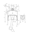
- FIG. 1 is a cross-sectional view of a main portion showing a schematic configuration of an internal combustion engine according to an embodiment of the present disclosure.
- FIG. 2 is a plan view showing a schematic configuration of the internal combustion engine in the cylinder axis direction.
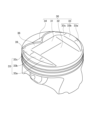
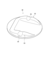
- FIG. 3 is a perspective view of a piston showing the shape of the piston top surface.
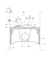
- FIG. 4 is a central cross-sectional view showing the piston.
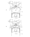
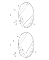
- FIG. 5(A) is a cross-sectional view of a main part of an internal combustion engine showing a state in which the piston has risen to the midpoint during the compression stroke
- FIG. 5(B) is a cross-sectional view of a main part of an internal combustion engine showing a state in which the piston has risen to top dead center during the compression stroke.
- FIG. 5(A) is a cross-sectional view of a main part of an internal combustion engine showing a state in which the piston has risen to top dead center during the compression stroke.
- FIG. 5(A) is a cross
- FIG. 6 is a perspective view of a main part of a piston, showing the airflow guided by the piston top surface.
- FIG. 7 is a plan view of the piston top surface in the cylinder axial direction, showing the flame injected from the sub-chamber.
- FIG. 8 is a perspective view of the piston top surface showing the grooves provided in the side guide portions.
- 9(A) and 9(B) are perspective views of the piston top surface showing first and second alternative embodiments of the protrusions.
- a pre-chamber internal combustion engine (hereinafter simply referred to as an "internal combustion engine") that employs a direct-injection internal combustion engine according to one embodiment of the present invention will be described with reference to Figures 1 to 8. Note that the present invention is not limited to the embodiment described below, and various modifications are possible as long as they have substantially the same configuration as this embodiment and provide similar effects.
- the cylinder axis direction Z of the internal combustion engine 1 refers to the direction in which the piston slides along the cylinder.
- the up-down direction it refers to the cylinder axis direction Z, with the cylinder head side being “up” and the crankshaft side being “down”.
- the intake and exhaust direction X refers to the direction connecting the intake port and the exhaust port.
- the “intake side” is the intake port side of the intake and exhaust direction X
- the “exhaust side” is the exhaust port side of the intake and exhaust direction X.
- the intake and exhaust direction X is also the fuel injection direction by the fuel injection nozzle.
- crankshaft direction Y refers to the extension direction of the crankshaft, and refers to the direction perpendicular to the cylinder axis direction Z and the intake and exhaust direction X.
- the crankshaft direction Y is also the direction of the cylinder rows arranged along the crankshaft. This configuration can be seen in FIG. 2.
- FIG. 1 is a cross-sectional view of a main portion showing a schematic configuration of an internal combustion engine according to an embodiment of the present disclosure
- Fig. 2 is a plan view showing a schematic configuration of the internal combustion engine in a cylinder axial direction Z.
- the internal combustion engine 1 includes a main combustion chamber 10 and an auxiliary combustion chamber 20 which form combustion chambers, an ignition plug 4, and a fuel injection nozzle 5.
- the internal combustion engine 1 of this embodiment is an in-line internal combustion engine in which a plurality of cylinders, each including a main combustion chamber 10 and an auxiliary combustion chamber 20, are arranged in series along a crankshaft 2.
- the arrangement of the cylinders may be a V-type or a horizontal type.
- the main chamber 10 is a space defined by a cylinder block 11 that forms a cylindrical cylinder 11a extending in the vertical direction, a cylinder head 12 that covers the upper end side of the cylinder 11a, and a piston 13 that reciprocates within the cylinder 11a.
- the auxiliary chamber 20 is a space defined by an auxiliary chamber wall 21 provided in the cylinder head 12.
- the auxiliary chamber 20 has the auxiliary chamber wall 21 and a communication passage 22 (injection port) that connects the main chamber 10 and the auxiliary chamber 20.
- the spark plug 4 is supported in the center of the cylinder head 12 and its tip side is disposed in the sub-chamber 20 separated by the sub-chamber wall 21 .
- a pair of intake ports 15 that are opened and closed by intake valves 14 are connected to one side of the cylinder head 12 in the intake and exhaust direction X, and a pair of exhaust ports 17 that are opened and closed via exhaust valves 16 are connected to the other side.
- a fuel supply nozzle 18 is disposed in the intake port 15. The fuel supply nozzle 18 can supply fuel into the main chamber 10 when the intake valve 14 opens. This configuration can be seen in Figures 1 and 2.
- the intake port 15 is connected to an intake passage (not shown), and the exhaust port 17 is connected to an exhaust passage (not shown).
- the piston 13 has a piston top surface 30 that faces the cylinder head 12 and thereby constitutes the lower part of the main chamber 10, and a pin hole 13a that is connected to the upper end side of the connecting rod 3 via a piston pin 19, and is connected to the crankshaft 2 via the connecting rod 3. This causes the piston 13 to reciprocate between the bottom dead center and the top dead center in the cylinder 11a in the vertical direction. See Figure 1 for this configuration.
- the auxiliary chamber wall 21 has a circular cross section centered on the cylinder axis (the axis that passes through the center of the piston 13 and extends in the cylinder axis direction Z) when viewed from above in the cylinder axis direction Z. This configuration can be seen in Figure 2.
- the auxiliary chamber wall 21 has a lower part that is hemispherical when viewed in the intake/exhaust direction X and the crank axis direction Y. This configuration can be seen in Figure 1.
- the communication passages 22 are formed along the circumferential direction of the auxiliary chamber wall 21 when viewed in a plan view in the cylinder axial direction Z, and connect the main chamber 10 and the auxiliary chamber 20.
- the fuel injection nozzle 5 is disposed outside the sub chamber 20, on the periphery of the cylinder head 12.
- the fuel injection nozzle 5 is disposed on the intake valve 14 side in the intake/exhaust direction X, more specifically, between the pair of intake valves 14, 14.
- This configuration can be seen in FIG. 2.
- the fuel injection nozzle 5 injects fuel directly toward the spark plug 4 in the auxiliary combustion chamber 20.
- a first communication passage 22A which is one of the communication passages 22, is arranged on the line of fire of the fuel injection from the fuel injection nozzle 5, i.e., on an extension line of the fuel injection port of the fuel injection nozzle 5. Therefore, the fuel injected from the fuel injection nozzle 5 can be directly supplied into the auxiliary combustion chamber 20 via the first communication passage 22A.
- the extension line of the first communication passage 22A also passes below the fuel injection nozzle 5. This configuration can be seen in Figures 1 and 5(A).
- the amount of fuel injected by the fuel injection nozzle 5 and the timing of fuel injection are controlled by a control
- the above-described internal combustion engine 1 can output power from the crankshaft 2 by repeating an intake stroke, a compression stroke, an expansion stroke, and an exhaust stroke to cause the piston 13 to reciprocate within the cylinder 11 a.
- fuel is supplied into the main combustion chamber 10 from a fuel supply nozzle 18 in the intake port 15 during the intake stroke.
- the intake air introduced into the main chamber 10 from the intake port 15 during the intake stroke is guided to the piston top surface 30, forming a tumble flow, which is a vortex air flow in the vertical direction (rotating around the crankshaft direction Y), within the main chamber 10.
- the shape of the piston top surface 30 makes it possible to stably form a tumble flow that does not impede the fuel injection from the fuel injection nozzle 5 to the spark plug 4 when the piston 13 moves upward during the compression stroke.
- the specific shape of the piston top surface 30 will be described later.
- the fuel and air-fuel mixture supplied to the auxiliary combustion chamber 20 is ignited by the spark plug 4 and combusted in the auxiliary combustion chamber 20.
- a flame F generated in the auxiliary combustion chamber 20 is injected from the communication passage 22 toward the main combustion chamber 10. This configuration can be seen in FIG. 7.
- the mixture formed in the main chamber 10 is combusted by the flame F injected from the auxiliary chamber 20 toward the main chamber 10 .
- Figure 3 is a perspective view of a piston showing the shape of the piston top surface
- Figure 4 is a central cross-sectional view of a piston
- Figure 5(A) is a cross-sectional view of a main part of an internal combustion engine showing the state in which the piston has risen to an intermediate point during the compression stroke, which will be described later
- Figure 5(B) is a cross-sectional view of a main part of an internal combustion engine showing the state in which the piston has risen to top dead center during the compression stroke
- Figure 6 is a perspective view of a main part of a piston showing the flow of the airflow guided by the piston top surface
- Figure 7 is a plan view of the piston top surface in the cylinder axial direction Z, showing the flame ejected from the auxiliary chamber.
- the circular piston top surface 30 When viewed from above in the cylinder axial direction Z, the circular piston top surface 30 has an inclined surface 31 and a flat surface 32 that are provided at the center of the crankshaft direction Y and extend along the intake/exhaust direction X, a pair of lateral guide portions 33, 33 provided on both sides of the inclined surface 31 and the flat surface 32 in the crankshaft direction Y, and a protrusion portion 34 and a valve recess 39 provided on the intake side of the inclined surface 31.
- the inclined surface 31 is formed on the intake port 15 side (intake side) in the intake/exhaust direction X, i.e., on the side where the fuel injection nozzle 5 is located.
- the inclined surface 31 extends in the intake/exhaust direction X and inclines toward the cylinder head 12 as it approaches the fuel injection nozzle 5.
- the inclined surface 31 is inclined upward toward the intake side.
- the inclined surface 31 has a first inclined surface 31a and a second inclined surface 31b that are continuously formed in that order from the exhaust side (the side opposite to the fuel injection nozzle 5) along the intake/exhaust direction X.
- the second inclined surface 31b which is disposed on the intake side, has a shorter length in the intake/exhaust direction X and a steeper angle of upward inclination toward the cylinder head 12. This configuration can be seen in FIG. 4.
- the inclined surface 31 is formed by the first inclined surface 31a and the second inclined surface 31b having different angles, but the inclined surface 31 may be formed by three or more inclined surfaces having different angles as long as the upward inclination angle becomes steeper in multiple stages toward the intake side (the fuel injection nozzle 5 side).
- the angle of the top of the inclined surface 31, in this embodiment, the angle of the second inclined surface 31b, is set so that when the vertical position of the piston 13 is within a predetermined range, the position where an extension line of the second inclined surface 31b parallel to the intake/exhaust direction X (hereinafter simply referred to as the extension line of the inclined surface 31) intersects with the wall surface of the cylinder 11a is lower (to the piston side) in the cylinder axial direction Z than the fuel injection nozzle 5.
- the intersection point of the extension line of the inclined surface 31 and the wall surface of the cylinder 11a is defined as a first contact point H1. This configuration can be seen in FIG. 4.
- the inclined surface 31 is formed so that, when the piston 13 is at least at the midpoint between the top dead center and the bottom dead center and closer to the bottom dead center, an extension of the inclined surface 31 intersects with the wall surface of the cylinder 11a at a first contact point H1.
- FIG. 5(A) the inclined surface 31 is formed so that, when the piston 13 is at the top dead center, an extension line of the inclined surface 31 passes between the fuel injection nozzle 5 and the spark plug 4 and intersects with the lower surface of the cylinder head 12. This configuration can be seen in FIG. 5(B).
- the inclined surface 31 be formed so that, at the timing when fuel is injected from the fuel injection nozzle 5, an extension line of the inclined surface 31 intersects with the wall surface of the cylinder 11a at the first contact point H1, as shown in Figure 5 (A).
- the higher the engine speed the closer the vertical position of the piston 13 is to the bottom dead center at the timing when fuel is injected from the fuel injection nozzle 5.
- the inclined surface 31 is formed so that when the piston 13 reaches top dead center, its top is located below the center line extending from the injection port 22a of the first communication passage 22A of the auxiliary chamber 20 when viewed in the crankshaft direction Y.
- This configuration can be seen in FIG. 5(B). This configuration prevents the inclined surface 31 from being directly hit by the flame F injected from the auxiliary chamber 20 toward the main chamber 10, and thus preventing the inclined surface 31 from being deteriorated.
- a downward slope 36 is formed, which slopes downward as it approaches the intake side.
- the downward slope 36 is connected to the top of the inclined surface 31.
- the flat surface 32 extends in the intake/exhaust direction X from the exhaust side end of the piston top surface 30 toward the intake side, and is continuous with the inclined surface 31.
- the flat surface 32 is formed as a plane extending parallel to the intake/exhaust direction X and the crankshaft direction Y so as to be perpendicular to the cylinder axial direction Z. This configuration may be seen in FIG.
- the flat surface 32 may be any surface capable of guiding the airflow toward the inclined surface by a smooth plane, and is not limited to a plane perpendicular to the cylinder axial direction Z.
- the flat surface 32 may be a gently inclined surface having an angle with the inclined surface 31.
- the intake side from the center of the piston 13 is defined as the inclined surface 31.
- the lateral guide portion 33 has a lateral guide surface 33a that slopes from the exhaust side end toward the cylinder head 12, a lateral extension surface 33b that extends approximately parallel to the piston top surface 30 from the intake side end of the lateral guide surface 33a, and a lateral downward surface 33c that slopes downward from the intake side end of the lateral extension surface 33b toward the piston top surface 30. That is, the side guide portion 33 protrudes toward the cylinder head 12 in the cylinder axial direction Z when viewed in the crankshaft direction Y, extends along the intake/exhaust direction X, and is formed in a generally mountain shape with the intake side end of the side guide surface 33a as the apex. This configuration can be seen in Fig. 4. Note that the side guide portion 33 may have the side extension surface 33b inclined in the same manner as the side downward surface 33c. In this case, the side extension surface 33b and the side downward surface 33c are in the same place.
- the angle of the side guide surface 33a is set so that, when the vertical position of the piston 13 is within a predetermined range, the position where an extension line of the side guide surface 33a parallel to the intake/exhaust direction X (hereinafter simply referred to as the extension line of the side guide surface 33a) intersects with the wall surface of the cylinder 11a is lower (to the piston side) in the cylinder axial direction Z than the first contact point H1. At this time, the intersection point of the extension line of the side guide surface 33a and the wall surface of the cylinder 11a is defined as the second contact point H2.
- the side guide surface 33a is formed to have a gentler inclination than the inclined surface 31.
- the top of the side guide surface 33a is located closer to the wall surface of the cylinder 11a in the intake/exhaust direction X than the top of the inclined surface 31.
- the second contact point H2 is located lower in the cylinder axial direction Z than the first contact point H1, and the intake/exhaust direction X is on the exhaust side.
- the side guide surface 33a is formed so that, when an extension line of the side guide surface 33a is extended along the inner wall of the cylinder 11a to the intake side in the intake/exhaust direction X while maintaining the vertical angle from the second contact point H2, the extension line reaches a third contact point H3 below the first contact point H1 below the fuel injection nozzle 5 (a position overlapping with the fuel injection nozzle 5 as viewed in the cylinder axial direction Z).
- a third contact point H3 below the first contact point H1 below the fuel injection nozzle 5 (a position overlapping with the fuel injection nozzle 5 as viewed in the cylinder axial direction Z).
- the lateral downward surface 33c slopes downward from the lateral extension surface 33b toward the intake side, and smoothly connects to the downward surface 36 arranged on the intake side of the inclined surface 31. In other words, the lateral downward surface 33c and the downward surface 36 are flush with each other. With this configuration, it is possible to prevent the airflow that flows in the intake/exhaust direction X along the inclined surface 31 and the flat surface 32, and the airflow that does not separate from the inclined surface 31 and the airflow that does not separate from the lateral guide surface 33a, from being disturbed on the intake side of the piston top surface 30. For this configuration, refer to Figures 2 and 6.
- the first separation angle ⁇ between the extension line of the inclined surface 31 and the downward surface 36 is set to be larger than the second separation angle ⁇ between the extension line of the lateral guide surface 33a and the lateral extension surface 33b.
- the airflow guided by the inclined surface 31, where the flow is strongest is more likely to separate from the top of the inclined surface 31, making the tumble flow guided by the piston top surface 30 more stable.
- the first separation angle ⁇ is larger than the second separation angle ⁇ .
- the guide width which is the width of the inclined surface 31 and the flat surface 32 in the crankshaft direction Y, is formed so as to gradually narrow toward the intake side in the intake and exhaust direction X.
- the inner surfaces (surfaces facing the cylinder axis) of the side guide parts 33 are inclined in the crankshaft direction Y so as to approach each other toward the intake side.
- the outer surfaces (surfaces facing the wall surface of the cylinder 11a) of the side guide parts 33 are formed in an arc shape along the wall surface of the cylinder 11a in the intake and exhaust direction X.
- the side guide parts 33 extend from the exhaust side to the intake side of the cylinder axis in the intake and exhaust direction X.
- each side guide part 33, 33 is largest at the point located at the center of the piston 13 in the intake and exhaust direction X.
- the inclination angle of the inner surface of the side guide parts 33 is determined so that the width in the crankshaft direction Y on the intake side of the point located at the center of the piston 13 in the intake and exhaust direction X of each side guide part 33, 33 is approximately constant.
- the protrusion 34 is a protrusion formed on the downward surface 36 toward the upper side.
- the protrusion 34 is formed so that the width in the crankshaft direction Y decreases toward the exhaust side in the intake and exhaust direction X.
- the width in the crankshaft direction Y of the intake side end of the protrusion 34 is formed larger than the width in the crankshaft direction Y of the tip of the fuel injection nozzle 5. This configuration can be seen in FIG. 2.
- the protrusion 34 is located between a pair of intake valves 14, 14.
- the protrusion 34 is formed by utilizing a trapezoidal portion of the valve recess 39, which is a recess formed according to the shape of the pair of intake valves 14, 14, between a pair of recesses corresponding to each intake valve 14, 14, as viewed from the cylinder axial direction Z. That is, the valve recess 39 is formed flush with the downward surface 36 and the lateral downward surface 33c, and the protrusion 34 protrudes upward from the downward surface 36.
- the protrusion 34 may be configured so that the surface in the crankshaft direction Y when viewed in the intake/exhaust direction X is inclined upward as it approaches the center of the protrusion 34. This configuration may be seen in FIG. 9(A).
- the shape of the protrusion 34 may be a trapezoid when viewed in the cylinder axial direction Z as shown in FIG. 2, or a diamond shape or the like. In other words, it is sufficient that the width of the exhaust side end of the protrusion 34 in the crankshaft direction Y becomes smaller as it approaches the exhaust side. This configuration may be seen in FIG. 9(B).
- the flow speed of the air flowing on the fuel injection nozzle 5 side of the inclined surface 31 becomes faster, and the tumble flow becomes more stable.
- the inclination angle of the inclined surface 31 gradually larger toward the fuel injection nozzle 5 side, the airflow guided by the inclined surface 31 can be easily separated smoothly at the end of the inclined surface 31. Therefore, the tumble flow formed by the inclined surface 31 becomes more stable.
- the flat surface 32 described above makes the downstream side of the airflow flowing along the piston top surface 30 flat, which prevents the airflow flowing toward the inclined surface 31 from separating from the piston top surface 30, making the tumble flow more stable.
- the above-described lateral guide portion 33 can guide the airflow flowing along the outer edge of the piston top surface 30 toward the fuel injection nozzle 5 to a second contact point H2 below the first contact point H1. This makes it possible to suppress the airflow guided by the lateral guide portions 33 from disturbing the airflow guided by the inclined surfaces 31. As a result, the above-mentioned tumble flow formed in the main chamber 10 by the piston top surfaces 30 becomes more stable.
- the lateral guide portion 33 is formed so that when the extension line of the lateral guide surface 33a is extended along the inner wall of the cylinder 11a toward the fuel injection nozzle 5 while maintaining the vertical angle from the second contact point H2, it reaches the third contact point H3 below the first contact point H1.
- the airflow guided by the lateral guide portion 33 can push up the airflow guided by the inclined surface 31, making the tumble flow more stable.
- the lateral guide portion 33 is formed so that the lateral downward surface 33c and the downward surface 36 are flush with each other, it is possible to suppress turbulence of the air flow flowing along the lateral downward surface 33c and the downward surface 36 without peeling off from the lateral guide surface 33a and the inclined surface 31, making the tumble flow more stable.
- the width of the lateral guide portion 33 approximately constant from its widest point in the crankshaft direction Y toward the fuel injection nozzle 5, it is possible to prevent the airflow flowing along the lateral guide portion 33 from being turbulent in the crankshaft direction Y, making the tumble flow more stable.
- the above-mentioned protrusion 34 allows the flame F1, which is part of the flame F injected from the auxiliary chamber 20 toward the main chamber 10 in a plan view in the cylinder axial direction Z and is injected from the first communication passage 22A toward the fuel injection nozzle 5, to be divided in the crankshaft direction Y and deflected away from the fuel injection nozzle 5. This reduces the effect of the flame F1 injected from the first communication passage 22A on the fuel injection nozzle 5.
- Fig. 8 is a perspective view of the piston top surface showing the groove provided in the side guide portion 33.
- the side guide portion 33 may be configured to extend in a direction intersecting the extending direction of the side guide portion 33 and to have a groove portion 35 provided as a passage portion that communicates between the inside and outside of the side guide portion 33.
- the groove portion 35 is recessed in the cylinder axial direction Z, extends in a direction intersecting the extension direction of the side guide portion 33, i.e., in the crankshaft direction Y, and opens on the inner and outer surfaces of the side guide portion 33.
- the depth of the groove 35 in the vertical direction (cylinder axial direction Z) is gradually increased from the outer side (the center side of the piston 13) toward the inner side in the extending direction of the groove 35.
- the width of the groove 35 in the extending direction of the side guide portion 33 (the intake/exhaust direction X) is formed so as to gradually increase from the inside toward the outside in the extending direction of the groove 35 .
- the groove 35 having this configuration by providing a pair of side guide portions 33 on the edge portion of the piston top surface 30, the flame F injected from the auxiliary chamber 20 can be efficiently transmitted to the gap formed between the outside of the side guide portions 33 in the width direction (crankshaft direction Y) and the wall surface of the cylinder 11a. Therefore, the side guide portions 33 provided on the piston top surface 30 can suppress the inhibition of the spread of the combustion of the mixture outside the side guide portions 33. In addition, the vertical depth of the groove portion 35 becomes deeper toward the inside in the extension direction of the groove portion 35, so that the flame F sprayed from the auxiliary chamber 20 is more easily guided to the groove portion 35.
- the width of the groove 35 becomes wider from the inside toward the outside in the extension direction of the groove 35, so that the flame F is more likely to propagate over a wider area on the outside in the width direction of the side guide portion 33. Therefore, the mixture is more likely to burn on the outside of the side guide portion 33.
- the groove portion 35 is a groove for guiding the flame F injected from the injection port 22a of the auxiliary chamber 20 from the inside to the outside of the side guide portion 33, the position is not limited to the position shown in Fig. 8. Specifically, the groove portion 35 only needs to be provided at a position where an extension line from each injection port 22a of the auxiliary chamber 20 intersects with the side guide portion 33 in a plan view in the cylinder axial direction Z, so as to extend along the extension line from the injection port 22a, and a configuration in which a plurality of groove portions are provided is also possible. However, the grooves 35 are not provided at positions adjacent to the tops of the inclined surfaces 31 of the lateral guide portions 33. This makes it possible to prevent the grooves 35 from disrupting the flow of the airflow guided along the inclined surfaces 31.
- the side guide portion 33 may be configured so that the width in the crankshaft direction Y on the exhaust side of the groove portion 35 is greater than the width in the crankshaft direction Y on the intake side of the groove portion 35. This makes it possible to suppress turbulence in the airflow caused by the airflow passing along the side guide portion 33 through the groove portion 35.
- the groove portion 35 is not limited to a groove recessed into the upper surface of the side guide portion 33, but may be a through hole drilled in a direction intersecting the extension direction of the side guide portion 33.
- the present embodiment shows an example of the present invention, and the present invention is not limited to the present embodiment.
- various modifications and improvements can be made to the present embodiment, and such modifications and improvements can also be included in the present invention.
- the features of the present invention are not limited to the internal combustion engine 1 using the auxiliary chamber 20 that houses the spark plug 4 within the main chamber 10, and similar effects can be expected as long as the internal combustion engine is provided with a fuel injection nozzle 5 that injects fuel toward the spark plug 4.
- the internal combustion engine of the present disclosure uses gasoline, the fuel is not limited to this and may be other fuels such as alcohol.
- the present specification discloses the following: (1) a cylinder formed by a cylinder block; a cylinder head covering one end of the cylinder; a piston having a top surface facing the cylinder head and reciprocating within the cylinder; a spark plug disposed in a center portion of the cylinder head in a combustion chamber defined between the cylinder, the cylinder head, and the piston; a fuel injection nozzle disposed within the combustion chamber; an intake port and an exhaust port provided in the cylinder head on either side of the spark plug;
- a cylinder injection type internal combustion engine comprising: the fuel injection nozzle is disposed on one side in an intake/exhaust direction connecting the intake port and the exhaust port, and injects fuel toward the ignition plug; a sloped surface that slopes toward the cylinder head as it approaches the fuel injection nozzle on the one side of the top surface of the piston;
- the inclined surface is formed so that, at least when the piston is located on the bottom dead center side of the midpoint between the top dead center and the bottom dead center, an extension line of the inclined surface intersect
- a flat surface continuous with the inclined surface is formed on the other side of the top surface of the piston in the intake/exhaust direction.
- a pair of side guide portions are provided on the top surface of the piston, the side guide portions being disposed on either side of the inclined surface in a direction perpendicular to the intake/exhaust direction and protruding toward the cylinder head side beyond the flat surface,
- the side guide portion has a side guide surface that is inclined toward the cylinder head side as it approaches the one side, and a position where an extension line of the side guide surface intersects with a wall surface of the cylinder is located closer to the piston than a position where an extension line of the inclined surface intersects with the wall surface of the cylinder.
- a direct injection type internal combustion engine according to (1) or (2).
- the airflow flowing from the exhaust side to the intake side in the intake/exhaust direction X along the edge of the piston top surface can be smoothly merged with the airflow guided by the wall surface of the cylinder 11a by the inclined surface, making the airflow formed by the piston top surface 30 more stable.
- the apex of the side guide surface is disposed on the other side of the apex of the inclined surface.
- a direct injection type internal combustion engine according to (3) According to this configuration, the airflow guided by the side guide surface 33a close to the wall surface of the cylinder 11a can be made to flow smoothly along the wall surface of the cylinder 11a.
- the top surface of the piston is formed with a downward surface that slopes toward the top surface from the top of the inclined surface toward the one side, and a side downward surface that slopes toward the top surface from the top of the side guide portion toward the one side, The downward surface and the side downward surface are formed flush with each other.
- the width of the side guide portion in a direction perpendicular to the intake and exhaust direction is gradually increased in a range from the end portion on the other side to a predetermined position in the intake and exhaust direction, and is formed to be approximately constant in a range from the predetermined position in the intake and exhaust direction to the one side.
- a sub-chamber is provided in the cylinder head so as to cover the ignition plug,
- the auxiliary chamber communicates with the combustion chamber and has an injection port for injecting flame from the auxiliary chamber to the combustion chamber,
- the inclined surface is located on the piston side with respect to the center line of the injection port.
- a direct injection type internal combustion engine according to any one of (3) to (6). According to this configuration, the flame F injected from the auxiliary chamber 20 into the main chamber 10 can be prevented from coming into contact with the inclined surface 31.
- the cylinder head is provided with an intake valve that opens and closes the intake port, and an exhaust valve that opens and closes the exhaust port,
- the intake valves are arranged in a pair in a cylinder axial direction, which is a reciprocating direction of the cylinder, and in a crank axial direction perpendicular to the intake and exhaust direction, the fuel injection nozzle is disposed between the pair of intake valves, a protrusion portion that is disposed between the pair of intake valves and narrows toward the other side is provided on the top surface of the piston,
- the injection port faces the protruding portion.
- a direct injection type internal combustion engine according to (7). According to this configuration, the flame F injected from the sub-chamber can be divided by the protruding portion and diverted away from the fuel injection flag.
Landscapes
- Engineering & Computer Science (AREA)
- Chemical & Material Sciences (AREA)
- Combustion & Propulsion (AREA)
- Mechanical Engineering (AREA)
- General Engineering & Computer Science (AREA)
- Combustion Methods Of Internal-Combustion Engines (AREA)
Abstract
燃焼室内に、点火プラグと、燃料噴射ノズルと、を備える筒内噴射式内燃機関であって、燃料噴射ノズルは、点火プラグに向けて燃料を噴射し、ピストン頂面には、燃料噴射ノズルに向かってシリンダヘッド側に傾斜する傾斜面が形成され、傾斜面は、ピストンが上死点と下死点との間の中間点より下死点に近い範囲にある場合には、傾斜面の延長線が、シリンダの壁面と交差し、ピストンが上死点にある場合には、傾斜面の延長線が、燃料噴射ノズルと点火プラグとの間で、シリンダヘッドの壁面と交差する、ように形成される。
Description
本発明は、燃焼室に燃料を噴射する燃料噴射ノズルを備えた筒内噴射式内燃機関に関する。
従来から、シリンダと、シリンダヘッドと、ピストンと、によって形成される燃焼室と、シリンダヘッドの中央部に配置された点火プラグと、燃焼室内に設けられ、燃料を供給する燃料噴射ノズルと、を備える筒内噴射式内燃機関が提案されている。このような筒内噴射式内燃機関は、吸気工程で吸気ポートを介して燃焼室内に供給された吸気と、燃料噴射ノズルにより供給された燃料とで、燃焼室内で混合気を形成し、圧縮工程で圧縮された混合気を点火プラグで点火する。
筒内噴射式内燃機関の吸気工程及び圧縮工程では、燃焼室に供給された吸気によって形成されるタンブル流によって、混合気が効率的に形成される。
このようなタンブル流が効率的に形成されるように、ピストン頂面に、吸気方向に向かって上方に湾曲する円筒面を有する中央隆起部と、同じく円筒面を有して中央隆起部の気筒列方向両側に位置する外側隆起部と、を設ける、特許文献1に記載の筒内噴射式内燃機関が提案されている。
しかし、上記特許文献1に記載の筒内噴射式内燃機関によれば、燃料噴射ノズルから噴射した燃料が、タンブル流の影響を強く受けて狙った箇所に燃料を供給できない場合があるという課題あった。
本発明は、前述した課題に鑑みてなされたものであり、圧縮工程時の燃焼室内の気流の流れが安定するとともに、燃料噴射ノズルから噴射される燃料を点火プラグ近傍により確実に導くことができる筒内噴射式内燃機関を提供することを目的とする。
本発明の上記目的は、下記の構成により達成される。
[1] シリンダブロックにより形成されるシリンダと、
前記シリンダの一端を覆うシリンダヘッドと、
前記シリンダヘッドに対向する頂面を備え、前記シリンダ内を往復動するピストンと、
前記シリンダと、前記シリンダヘッドと、前記ピストンと、の間に形成される燃焼室内において、前記シリンダヘッドの中央部に配置された点火プラグと、
前記燃焼室内に配置された燃料噴射ノズルと、
前記点火プラグを挟んで前記シリンダヘッドに設けられた吸気口及び排気口と、
を備える筒内噴射式内燃機関であって、
前記燃料噴射ノズルは、前記吸気口と前記排気口とを結ぶ吸排気方向の一方側に配置され、前記点火プラグに向けて燃料を噴射し、
前記ピストンの前記頂面の前記一方側には、前記燃料噴射ノズル側に向かうにつれて前記シリンダヘッド側に傾斜する傾斜面が形成され、
前記傾斜面は、少なくとも前記ピストンが上死点と下死点との間の中間点より下死点側にある場合には、前記傾斜面の延長線が、前記燃料噴射ノズルより前記ピストン側で前記シリンダの壁面と交差し、前記ピストンが前記上死点にある場合には、前記傾斜面の延長線が、前記燃料噴射ノズルと前記点火プラグとの間で、前記シリンダヘッドの壁面と交差する、ように形成される、
筒内噴射式内燃機関。
[2] 前記ピストンの前記頂面の前記吸排気方向の他方側には、前記傾斜面と連続するフラット面が形成された、
[1]に記載の筒内噴射式内燃機関。
[3] 前記ピストンの前記頂面には、前記吸排気方向に直交する方向で前記傾斜面を挟むように配置され、前記フラット面よりも前記シリンダヘッド側に突設した一対の側方ガイド部が設けられ、
前記側方ガイド部は、前記一方側に向かうにつれて前記シリンダヘッド側に傾斜する側方ガイド面を有し、前記側方ガイド面の延長線が前記シリンダの壁面と交差する位置を、前記傾斜面の延長線が前記シリンダの壁面と交差する位置よりも、前記ピストン側にした、
[2]に記載の筒内噴射式内燃機関。
[4] 前記側方ガイド面の頂部を、前記傾斜面の頂部よりも前記他方側に配置した、
[3]に記載の筒内噴射式内燃機関。
[5] 前記ピストンの前記頂面には、前記傾斜面の頂部から前記一方側に向かうにつれて前記頂面側に傾斜する下り面と、前記側方ガイド部の頂部から前記一方側に向かうにつれて前記頂面側に傾斜する側方下り面と、が形成され、
前記下り面と、前記側方下り面と、が面一に形成された、
[3]に記載の筒内噴射式内燃機関。
[6] 前記シリンダの往復方向であるシリンダ軸方向視で、前記側方ガイド部の前記吸排気方向と直交する方向の幅を、前記他方側の端部から前記吸排気方向の所定位置までの範囲では徐々に拡幅し、前記吸排気方向の所定の位置から前記一方側の範囲では略一定となるように形成した、
[3]に記載の筒内噴射式内燃機関。
[7] 前記点火プラグを覆うように前記シリンダヘッドに設けられた副室を有し、
前記副室は、前記燃焼室と前記副室とを連通し、前記副室から前記燃焼室へと火炎を噴射する噴射口を有し、
前記ピストンが前記上死点にある場合に、前記傾斜面が前記噴射口の中心線より前記ピストン側に位置するようにした、
[3]に記載の筒内噴射式内燃機関。
[8] 前記シリンダヘッドには、前記吸気口を開閉する吸気バルブと、前記排気口を開閉する排気バルブと、が設けられ、
前記吸気バルブは、前記シリンダの往復方向であるシリンダ軸方向視及び前記吸排気方向と直交するクランク軸方向に並べて一対配置され、
前記燃料噴射ノズルは、一対の前記吸気バルブの間に配置され、
前記ピストンの前記頂面には、一対の前記吸気バルブの間に配置されて、前記他方側に向かうにつれて幅狭に形成される突設部が設けられ、
前記噴射口は、前記突設部と対向する、
[7]に記載の筒内噴射式内燃機関。
[1] シリンダブロックにより形成されるシリンダと、
前記シリンダの一端を覆うシリンダヘッドと、
前記シリンダヘッドに対向する頂面を備え、前記シリンダ内を往復動するピストンと、
前記シリンダと、前記シリンダヘッドと、前記ピストンと、の間に形成される燃焼室内において、前記シリンダヘッドの中央部に配置された点火プラグと、
前記燃焼室内に配置された燃料噴射ノズルと、
前記点火プラグを挟んで前記シリンダヘッドに設けられた吸気口及び排気口と、
を備える筒内噴射式内燃機関であって、
前記燃料噴射ノズルは、前記吸気口と前記排気口とを結ぶ吸排気方向の一方側に配置され、前記点火プラグに向けて燃料を噴射し、
前記ピストンの前記頂面の前記一方側には、前記燃料噴射ノズル側に向かうにつれて前記シリンダヘッド側に傾斜する傾斜面が形成され、
前記傾斜面は、少なくとも前記ピストンが上死点と下死点との間の中間点より下死点側にある場合には、前記傾斜面の延長線が、前記燃料噴射ノズルより前記ピストン側で前記シリンダの壁面と交差し、前記ピストンが前記上死点にある場合には、前記傾斜面の延長線が、前記燃料噴射ノズルと前記点火プラグとの間で、前記シリンダヘッドの壁面と交差する、ように形成される、
筒内噴射式内燃機関。
[2] 前記ピストンの前記頂面の前記吸排気方向の他方側には、前記傾斜面と連続するフラット面が形成された、
[1]に記載の筒内噴射式内燃機関。
[3] 前記ピストンの前記頂面には、前記吸排気方向に直交する方向で前記傾斜面を挟むように配置され、前記フラット面よりも前記シリンダヘッド側に突設した一対の側方ガイド部が設けられ、
前記側方ガイド部は、前記一方側に向かうにつれて前記シリンダヘッド側に傾斜する側方ガイド面を有し、前記側方ガイド面の延長線が前記シリンダの壁面と交差する位置を、前記傾斜面の延長線が前記シリンダの壁面と交差する位置よりも、前記ピストン側にした、
[2]に記載の筒内噴射式内燃機関。
[4] 前記側方ガイド面の頂部を、前記傾斜面の頂部よりも前記他方側に配置した、
[3]に記載の筒内噴射式内燃機関。
[5] 前記ピストンの前記頂面には、前記傾斜面の頂部から前記一方側に向かうにつれて前記頂面側に傾斜する下り面と、前記側方ガイド部の頂部から前記一方側に向かうにつれて前記頂面側に傾斜する側方下り面と、が形成され、
前記下り面と、前記側方下り面と、が面一に形成された、
[3]に記載の筒内噴射式内燃機関。
[6] 前記シリンダの往復方向であるシリンダ軸方向視で、前記側方ガイド部の前記吸排気方向と直交する方向の幅を、前記他方側の端部から前記吸排気方向の所定位置までの範囲では徐々に拡幅し、前記吸排気方向の所定の位置から前記一方側の範囲では略一定となるように形成した、
[3]に記載の筒内噴射式内燃機関。
[7] 前記点火プラグを覆うように前記シリンダヘッドに設けられた副室を有し、
前記副室は、前記燃焼室と前記副室とを連通し、前記副室から前記燃焼室へと火炎を噴射する噴射口を有し、
前記ピストンが前記上死点にある場合に、前記傾斜面が前記噴射口の中心線より前記ピストン側に位置するようにした、
[3]に記載の筒内噴射式内燃機関。
[8] 前記シリンダヘッドには、前記吸気口を開閉する吸気バルブと、前記排気口を開閉する排気バルブと、が設けられ、
前記吸気バルブは、前記シリンダの往復方向であるシリンダ軸方向視及び前記吸排気方向と直交するクランク軸方向に並べて一対配置され、
前記燃料噴射ノズルは、一対の前記吸気バルブの間に配置され、
前記ピストンの前記頂面には、一対の前記吸気バルブの間に配置されて、前記他方側に向かうにつれて幅狭に形成される突設部が設けられ、
前記噴射口は、前記突設部と対向する、
[7]に記載の筒内噴射式内燃機関。
本発明の筒内噴射式内燃機関によれば、圧縮工程時の燃焼室内の気流の流れが安定するとともに、燃料噴射ノズルから噴射される燃料を点火プラグ近傍により確実に導くことができる。
本発明の一実施形態に係る筒内噴射式内燃機関を適用した副室式内燃機関(以下、単に「内燃機関とも称する)について、図1~図8を用いて説明する。なお、本発明は、以下で説明する実施形態に何ら限定されるものではなく、本実施形態と実質的に同一の構成を有し、且つ、同様な作用効果を奏しさえすれば、多様な変更が可能である。
なお、内燃機関1に関して、本明細書では、シリンダ軸方向Zとは、シリンダに沿ってピストンが摺動する方向を示す。上下方向と記す場合は、シリンダ軸方向Zを示し、シリンダヘッド側を「上」、クランク軸側を「下」とする。この構成は、図1を参照するとよい。また、吸排気方向Xとは、吸気ポート及び排気ポートを結ぶ方向を示す。「吸気側」を吸排気方向Xの吸気ポート側、「排気側」を吸排気方向Xの排気ポート側とする。吸排気方向Xは、燃料噴射ノズルによる燃料噴射方向でもある。また、クランク軸方向Yとは、クランク軸の延在方向であって、シリンダ軸方向Z及び吸排気方向Xに直交する方向を示す。クランク軸方向Yは、クランク軸に沿って並べて配置される気筒列方向でもある。この構成は、図2を参照するとよい。
(全体構成)
図1は、本開示の一実施形態による内燃機関の概略構成を示す要部断面図であり、図2は、内燃機関の概略構成を示すシリンダ軸方向Zの平面図である。内燃機関1は、燃焼室を形成する主室10及び副室20と、点火プラグ4と、燃料噴射ノズル5と、を備える。
本実施形態の内燃機関1は、主室10及び副室20を含む気筒がクランク軸2に沿って直列に複数配列された直列型内燃機関である。気筒の配列はV型であっても水平型であってもよい。
図1は、本開示の一実施形態による内燃機関の概略構成を示す要部断面図であり、図2は、内燃機関の概略構成を示すシリンダ軸方向Zの平面図である。内燃機関1は、燃焼室を形成する主室10及び副室20と、点火プラグ4と、燃料噴射ノズル5と、を備える。
本実施形態の内燃機関1は、主室10及び副室20を含む気筒がクランク軸2に沿って直列に複数配列された直列型内燃機関である。気筒の配列はV型であっても水平型であってもよい。
主室10は、上下方向に延在する筒状のシリンダ11aを形成するシリンダブロック11と、シリンダ11aの上端側を覆うシリンダヘッド12と、シリンダ11a内を往復動するピストン13と、で画定された空間である。
副室20は、シリンダヘッド12に設けられた副室壁21で画定された空間である。副室20は、副室壁21と、主室10と副室20との間を連通する連通路22(噴射口)と、を有する。
点火プラグ4は、シリンダヘッド12の中央部に支持されて、その先端側が副室壁21で隔てた副室20内に配置される。
副室20は、シリンダヘッド12に設けられた副室壁21で画定された空間である。副室20は、副室壁21と、主室10と副室20との間を連通する連通路22(噴射口)と、を有する。
点火プラグ4は、シリンダヘッド12の中央部に支持されて、その先端側が副室壁21で隔てた副室20内に配置される。
シリンダヘッド12は、吸排気方向Xの一方側には吸気バルブ14によって開閉される一対の吸気ポート15が接続され、他方側には排気バルブ16を介して開閉される一対の排気ポート17が接続されている。吸気ポート15内には、燃料供給ノズル18が配置されている。燃料供給ノズル18は、吸気バルブ14が開弁した際に主室10内に燃料を供給できる。この構成は、図1及び図2を参照するとよい。
なお、吸気ポート15は、図示しない吸気通路に接続される。排気ポート17は、図示しない排気通路に接続される。
なお、吸気ポート15は、図示しない吸気通路に接続される。排気ポート17は、図示しない排気通路に接続される。
ピストン13は、シリンダヘッド12に対向することにより主室10の下部を構成するピストン頂面30と、ピストンピン19を介してコンロッド3の上端側に連結されるピン孔13aと、を有し、コンロッド3を介してクランク軸2に接続されている。これにより、ピストン13は、上下方向のシリンダ11a内の下死点と上死点との間を往復動する。この構成は、図1を参照するとよい。
副室壁21は、シリンダ軸方向Zの平面視で、シリンダ軸(ピストン13の中心を通りシリンダ軸方向Zに延びる軸)を中心とした円形の断面を有している。この構成は、図2を参照するとよい。副室壁21は、吸排気方向X及びクランク軸方向Y視で下部が半球状に形成されている。この構成は、図1を参照するとよい。
連通路22は、シリンダ軸方向Zの平面視で、副室壁21の周方向に沿って複数形成され、主室10と副室20とを連通する。
燃料噴射ノズル5は、副室20の外側であって、シリンダヘッド12の周縁部に配置されている。燃料噴射ノズル5は、吸排気方向Xで吸気バルブ14側、より具体的には、一対の吸気バルブ14、14の間に配置されている。この構成は、図2を参照するとよい。
燃料噴射ノズル5は、副室20内の点火プラグ4に向けて直接燃料を噴射する。燃料噴射ノズル5からの燃料噴射の射線上、すなわち燃料噴射ノズル5の燃料噴射口の延長線上には、複数設けた連通路22のうちの1つである第1連通路22Aが配置される。このため、第1連通路22Aを介して、燃料噴射ノズル5から噴射される燃料を副室20内に直接供給できる。また、第1連通路22Aの延長線は、燃料噴射ノズル5より下方を通る。この構成は、図1及び図5(A)を参照するとよい。
なお、燃料噴射ノズル5による燃料の噴射量と燃料を噴射するタイミングとは、図示しない制御部によって制御される。
燃料噴射ノズル5は、副室20内の点火プラグ4に向けて直接燃料を噴射する。燃料噴射ノズル5からの燃料噴射の射線上、すなわち燃料噴射ノズル5の燃料噴射口の延長線上には、複数設けた連通路22のうちの1つである第1連通路22Aが配置される。このため、第1連通路22Aを介して、燃料噴射ノズル5から噴射される燃料を副室20内に直接供給できる。また、第1連通路22Aの延長線は、燃料噴射ノズル5より下方を通る。この構成は、図1及び図5(A)を参照するとよい。
なお、燃料噴射ノズル5による燃料の噴射量と燃料を噴射するタイミングとは、図示しない制御部によって制御される。
上述の内燃機関1は、吸気工程、圧縮工程、膨張工程及び排気工程を繰り返すことによってピストン13をシリンダ11a内に沿って往復動させ、クランク軸2から動力を出力できる。
なお、上述の内燃機関1は、吸気工程で吸気ポート15内の燃料供給ノズル18から主室10内に燃料が供給される。
なお、上述の内燃機関1は、吸気工程で吸気ポート15内の燃料供給ノズル18から主室10内に燃料が供給される。
このとき、吸気工程で吸気ポート15から主室10内に導入された吸気が、ピストン頂面30にガイドされることによって、主室10内に縦方向(クランク軸方向Yを中心に回転する)の渦状の気流であるタンブル流が形成される。
本実施例では、ピストン頂面30の形状によって、圧縮工程でピストン13が上昇作動する際に、燃料噴射ノズル5による点火プラグ4への燃料噴射を阻害しないタンブル流を安定して形成することができる。ピストン頂面30の具体的な形状については後述する。
本実施例では、ピストン頂面30の形状によって、圧縮工程でピストン13が上昇作動する際に、燃料噴射ノズル5による点火プラグ4への燃料噴射を阻害しないタンブル流を安定して形成することができる。ピストン頂面30の具体的な形状については後述する。
また、圧縮行程では、ピストン13が上昇している最中に、所定のタイミングで燃料噴射ノズル5から副室20内の点火プラグ4に向けて燃料が噴射され、副室20内を燃料で満たす。この構成は、図5(A)を参照するとよい。
圧縮工程において副室20内に供給された燃料と混合気は、点火プラグ4によって点火されて副室20内で燃焼される。これにより、副室20内で発生した火炎Fが連通路22から主室10に向けて噴射される。この構成は、図7を参照するとよい。
副室20から主室10に向けて噴射された火炎Fによって、主室10内に形成された混合気が燃焼する。
副室20から主室10に向けて噴射された火炎Fによって、主室10内に形成された混合気が燃焼する。
次に、図2~図7に基づき、ピストン頂面の具体的な形状について説明する。図3は、ピストン頂面の形状を示したピストンの斜視図であり、図4は、ピストンを示した中央横断面図であり、図5(A)は、圧縮工程時に後述する中間点までピストンが上昇した状態を示した内燃機関の要部断面図であり、図5(B)は、圧縮工程時に上死点までピストンが上昇した状態を示した内燃機関の要部断面図であり、図6は、ピストン頂面によってガイドされる気流の流れを示したピストンの要部斜視図であり、図7は、副室から噴射される火炎を示したピストン頂面のシリンダ軸方向Zの平面図である。
シリンダ軸方向Zの平面視において、円形のピストン頂面30には、クランク軸方向Yの中央側に設けられ、吸排気方向Xに沿って延在する傾斜面31及びフラット面32と、傾斜面31及びフラット面32に対して、クランク軸方向Yの両側に設けられた一対の側方ガイド部33,33と、傾斜面31より吸気側に設けられた突設部34及びバルブリセス39と、を有する。
傾斜面31は、吸排気方向Xにおいて、吸気ポート15側(吸気側)、すなわち燃料噴射ノズル5が配置された側に形成される。
傾斜面31は、吸排気方向Xに延在し、燃料噴射ノズル5に向かうにつれてシリンダヘッド12側に傾斜する面である。言い換えると、傾斜面31は、吸気側に向かって上方傾斜する面である。
具体的に説明すると、傾斜面31は、第1傾斜面31aと、第2傾斜面31bと、が吸排気方向Xに沿って排気側(燃料噴射ノズル5とは反対側)から順番に連続的に形成されている。第1傾斜面31aと、第2傾斜面31bと、は吸気側に配置される第2傾斜面31bの方が、吸排気方向Xの長さが短くなるとともに、シリンダヘッド12側への上方傾斜の角度も急になる。この構成は、図4を参照するとよい。
なお、図4に示す例では、傾斜面31を、角度の異なる第1傾斜面31a及び第2傾斜面31bで形成したが、傾斜面31は、吸気側(燃料噴射ノズル5側)に向かうにつれて上方傾斜の角度が多段階で急になる傾斜角度となっていればよく、傾斜面31を角度の異なる3つ以上の傾斜面から形成してもよい。
具体的に説明すると、傾斜面31は、第1傾斜面31aと、第2傾斜面31bと、が吸排気方向Xに沿って排気側(燃料噴射ノズル5とは反対側)から順番に連続的に形成されている。第1傾斜面31aと、第2傾斜面31bと、は吸気側に配置される第2傾斜面31bの方が、吸排気方向Xの長さが短くなるとともに、シリンダヘッド12側への上方傾斜の角度も急になる。この構成は、図4を参照するとよい。
なお、図4に示す例では、傾斜面31を、角度の異なる第1傾斜面31a及び第2傾斜面31bで形成したが、傾斜面31は、吸気側(燃料噴射ノズル5側)に向かうにつれて上方傾斜の角度が多段階で急になる傾斜角度となっていればよく、傾斜面31を角度の異なる3つ以上の傾斜面から形成してもよい。
傾斜面31の頂部での角度、本実施形態では、第2傾斜面31bの角度は、ピストン13の上下位置が所定の範囲内にある場合には、第2傾斜面31bの吸排気方向Xと平行な延長線(以下単に、傾斜面31の延長線)と、シリンダ11aの壁面と、が交差する位置が、燃料噴射ノズル5よりもシリンダ軸方向Zで下方側(ピストン側)となるように設定される。このとき、傾斜面31の延長線と、シリンダ11aの壁面と、の交点を第1接触点H1とする。この構成は、図4を参照するとよい。
具体的に説明すると、傾斜面31は、ピストン13が少なくとも上死点と下死点の中間である中間点よりも下死点側にある場合には、傾斜面31の延長線がシリンダ11aの壁面と第1接触点H1で交差するように形成される。この構成は、図5(A)を参照するとよい。
その一方で、傾斜面31は、ピストン13が上死点にある場合には、傾斜面31の延長線が燃料噴射ノズル5と点火プラグ4の間を通りシリンダヘッド12の下面と交差するように形成される。この構成は、図5(B)を参照するとよい。
具体的に説明すると、傾斜面31は、ピストン13が少なくとも上死点と下死点の中間である中間点よりも下死点側にある場合には、傾斜面31の延長線がシリンダ11aの壁面と第1接触点H1で交差するように形成される。この構成は、図5(A)を参照するとよい。
その一方で、傾斜面31は、ピストン13が上死点にある場合には、傾斜面31の延長線が燃料噴射ノズル5と点火プラグ4の間を通りシリンダヘッド12の下面と交差するように形成される。この構成は、図5(B)を参照するとよい。
なお、傾斜面31は、図5(A)に示されるように、燃料噴射ノズル5から燃料を噴射するタイミングにおいて、傾斜面31の延長線が第1接触点H1でシリンダ11aの壁面と交差する、ように形成することが好ましい。
この場合、燃料噴射ノズル5から燃料が噴射されるタイミングにおけるピストン13の上下位置は、エンジンの回転数が高くなるほど下死点側に近づく。このため、エンジン回転数が5千回転程度の高回転の場合の燃料噴射タイミングで傾斜面31の延長線がシリンダ11aの壁面に交差するように設定するとよい。
この場合、燃料噴射ノズル5から燃料が噴射されるタイミングにおけるピストン13の上下位置は、エンジンの回転数が高くなるほど下死点側に近づく。このため、エンジン回転数が5千回転程度の高回転の場合の燃料噴射タイミングで傾斜面31の延長線がシリンダ11aの壁面に交差するように設定するとよい。
さらに、傾斜面31は、ピストン13が上死点に到達した場合に、クランク軸方向Y視で、その頂部が副室20の第1連通路22Aの噴射口22aから延長した中心線よりも下方に位置するように形成される。この構成は、図5(B)を参照するとよい。該構成によれば、傾斜面31に副室20から主室10に向けて噴射する火炎Fが直接当たって、傾斜面31が劣化することを防止できる。
また、傾斜面31より吸気側には、吸気側に向かうにつれて下方に傾斜する下り面36が形成されている。下り面36は、傾斜面31の頂部に連結されている。
フラット面32は、ピストン頂面30の排気側端部から吸気側に向かい吸排気方向Xに延設され、傾斜面31と連続する。本実施形態では、フラット面32は、シリンダ軸方向Zと直交するように吸排気方向X及びクランク軸方向Yに平行に延びる平面で形成されている。この構成は、図4を参照するとよい。
なお、フラット面32は、滑らかな平面によって気流を傾斜面に向けてガイドできる面であればよく、シリンダ軸方向Zに対して直交する平面には限られない。例えば、フラット面32は、傾斜面31と角度を有するように緩やかに傾斜した面としてもよい。フラット面32を傾斜面31と同方向に傾斜させる場合は、ピストン13の中心より吸気側を傾斜面31と定義する。傾斜面31より排気側をフラット面32とすることで、ピストン頂面30に沿って流れる気流が、傾斜面31より排気側でピストン頂面30から剥離することを抑制できる。
なお、フラット面32は、滑らかな平面によって気流を傾斜面に向けてガイドできる面であればよく、シリンダ軸方向Zに対して直交する平面には限られない。例えば、フラット面32は、傾斜面31と角度を有するように緩やかに傾斜した面としてもよい。フラット面32を傾斜面31と同方向に傾斜させる場合は、ピストン13の中心より吸気側を傾斜面31と定義する。傾斜面31より排気側をフラット面32とすることで、ピストン頂面30に沿って流れる気流が、傾斜面31より排気側でピストン頂面30から剥離することを抑制できる。
側方ガイド部33は、排気側端部からシリンダヘッド12側に向けて傾斜する側方ガイド面33aと、側方ガイド面33aの吸気側端部からピストン頂面30に対して略平行に延設された側方延設面33bと、側方延設面33bの吸気側端部からピストン頂面30に向けて下方傾斜する側方下り面33cと、を有する。
すなわち、側方ガイド部33は、クランク軸方向Y視で、シリンダ軸方向Zでシリンダヘッド12側に突出するとともに、吸排気方向Xに沿って延在し、側方ガイド面33aの吸気側端部を頂部とする略山型に形成されている。この構成は、図4を参照するとよい。なお、側方ガイド部33は、側方延設面33bを側方下り面33cと同様に傾斜させてもよい。この場合、側方延設面33bと側方下り面33c同一箇所となる。
すなわち、側方ガイド部33は、クランク軸方向Y視で、シリンダ軸方向Zでシリンダヘッド12側に突出するとともに、吸排気方向Xに沿って延在し、側方ガイド面33aの吸気側端部を頂部とする略山型に形成されている。この構成は、図4を参照するとよい。なお、側方ガイド部33は、側方延設面33bを側方下り面33cと同様に傾斜させてもよい。この場合、側方延設面33bと側方下り面33c同一箇所となる。
側方ガイド面33aの角度は、ピストン13の上下位置が所定の範囲内にある場合には、側方ガイド面33aの吸排気方向Xと平行な延長線(以下単に、側方ガイド面33aの延長線)と、シリンダ11aの壁面と、が交差する位置が、第1接触点H1よりもシリンダ軸方向Zで下方側(ピストン側)となるように設定される。このとき、側方ガイド面33aの延長線と、シリンダ11aの壁面と、の交点を第2接触点H2とする。
また、側方ガイド面33aは、傾斜面31よりも傾斜が緩く形成される。これは、側方ガイド面33aの頂部は、傾斜面31の頂部と比較して、吸排気方向Xにおいてシリンダ11aの壁面と近い位置に配置されるからである。側方ガイド面33aを、傾斜面31よりも傾斜が緩く形成することにより、第2接触点H2は、第1接触点H1と比較してシリンダ軸方向Zが下側になり、吸排気方向Xが排気側となる。
さらに、側方ガイド面33aは、図6に示すように、側方ガイド面33aの延長線が、第2接触点H2から上下方向の角度を維持したまま、シリンダ11aの内壁に沿わせて吸排気方向Xの吸気側に延長した場合に、燃料噴射ノズル5の下側(シリンダ軸方向Z視で燃料噴射ノズル5と重なる位置)で第1接触点H1より下側の第3接触点H3に到達するように形成される。この構成は、図4及び図6を参照するとよい。
また、側方ガイド面33aは、傾斜面31よりも傾斜が緩く形成される。これは、側方ガイド面33aの頂部は、傾斜面31の頂部と比較して、吸排気方向Xにおいてシリンダ11aの壁面と近い位置に配置されるからである。側方ガイド面33aを、傾斜面31よりも傾斜が緩く形成することにより、第2接触点H2は、第1接触点H1と比較してシリンダ軸方向Zが下側になり、吸排気方向Xが排気側となる。
さらに、側方ガイド面33aは、図6に示すように、側方ガイド面33aの延長線が、第2接触点H2から上下方向の角度を維持したまま、シリンダ11aの内壁に沿わせて吸排気方向Xの吸気側に延長した場合に、燃料噴射ノズル5の下側(シリンダ軸方向Z視で燃料噴射ノズル5と重なる位置)で第1接触点H1より下側の第3接触点H3に到達するように形成される。この構成は、図4及び図6を参照するとよい。
側方下り面33cは、側方延設面33bから吸気側に向かって下方傾斜しており、傾斜面31の吸気側に配置された下り面36と滑らかに連接している。すなわち、側方下り面33cと下り面36とは面一になっている。該構成によれば、傾斜面31及びフラット面32に沿って吸排気方向Xに流れる気流のうち、傾斜面31から剥離しなかった気流や、側方ガイド面33aから剥離しなかった気流が、ピストン頂面30の吸気側で乱れることを抑制できる。この構成は、図2及び図6を参照するとよい。
上記のように、傾斜面31の延長線と、下り面36との間にできる第1剥離角度αを、側方ガイド面33aの延長線と、側方延設面33bとの間にできる第2剥離角度βよりも大きくした。該構成によれば、最も流れが強くなる傾斜面31によってガイドされる気流が、傾斜面31の頂部から剥離し易くなるため、ピストン頂面30によってガイドされるタンブル流がより安定する。この構成は、図4を参照するとよい。なお、側方延設面33bを傾斜させた場合でも、第1剥離角度αが第2剥離角度βよりも大きくなるようにすることが好ましい。
傾斜面31及びフラット面32のクランク軸方向Yの幅であるガイド幅は、吸排気方向Xで吸気側に向かうにつれて徐々に狭くなるように形成されている。具体的には、側方ガイド部33の内面(シリンダ軸を向く面)が吸気側に向かうにつれて互いに近づくようにクランク軸方向Yで傾斜している。また、側方ガイド部33の外面(シリンダ11aの壁面を向く面)は、吸排気方向Xでシリンダ11aの壁面に沿って円弧状に形成されている。側方ガイド部33は、吸排気方向Xでシリンダ軸より排気側から吸気側まで延びている。したがって、各側方ガイド部33、33のクランク軸方向Yの幅は、吸排気方向Xでピストン13の中心に位置する箇所が最も大きくなる。そして、各側方ガイド部33、33の吸排気方向Xでピストン13の中心に位置する箇所より吸気側のクランク軸方向Yの幅は、略一定になるように側方ガイド部33の内面の傾斜角度が決定されている。
突設部34は、下り面36に上側に向けて形成された突起である。突設部34は、吸排気方向Xにおいて排気側に向かうにつれてクランク軸方向Yの幅が小さくなるように形成されている。そして、突設部34の吸気側端部のクランク軸方向Yの幅は、燃料噴射ノズル5の先端のクランク軸方向Yの幅よりも大きく形成されている。この構成は、図2を参照するとよい。本実施形態では、突設部34は、一対の吸気バルブ14、14の間に位置している。具体的には、突設部34は、一対の吸気バルブ14、14の形状にあわせて形成された凹部であるバルブリセス39の、各吸気バルブ14、14に対応する一対の凹部の間の、シリンダ軸方向Zから視て台形形状となっている部分を利用して形成されている。すなわち、バルブリセス39は下り面36及び側方下り面33cと面一に形成されており、突設部34は下り面36から上方に突設されている。なお、突設部34は、吸排気方向X視でクランク軸方向Yの面が突設部34の中央部に向かうにつれて上方に傾斜するようにしてもよい。この構成は、図9(A)を参照するとよい。このようにすることで、下り面36及び側方下り面33cに沿って流れる気流を上方へ案内することができる。また、突設部34の形状は、図2のようなシリンダ軸方向Z視で台形形状の他に、菱形形状等であってもよい。すなわち、突設部34の排気側端部のクランク軸方向Yの幅が、排気側に向かうにつれて小さくなっていればよい。この構成は、図9(B)を参照するとよい。
(作用効果)
次に、上述のピストン頂面30の形状による作用効果について説明する。
上述の傾斜面31によれば、図5(A)に示されるように、内燃機関1の圧縮工程時において、ピストン13がシリンダ11aの中間点より下死点側にある場合には、ピストン頂面30を燃料噴射ノズル5側へと流れる気流を、燃料噴射ノズル5の下方側である第1接触点H1にて、シリンダ11aの吸気側壁面に接触するようにガイドできる。
これにより、主室10内に発生するタンブル流によって、燃料噴射ノズル5から点火プラグ4に向けて噴射する燃料がシリンダヘッド12側に流され、噴射位置の狙いが上方にズレることを抑制できる。
次に、上述のピストン頂面30の形状による作用効果について説明する。
上述の傾斜面31によれば、図5(A)に示されるように、内燃機関1の圧縮工程時において、ピストン13がシリンダ11aの中間点より下死点側にある場合には、ピストン頂面30を燃料噴射ノズル5側へと流れる気流を、燃料噴射ノズル5の下方側である第1接触点H1にて、シリンダ11aの吸気側壁面に接触するようにガイドできる。
これにより、主室10内に発生するタンブル流によって、燃料噴射ノズル5から点火プラグ4に向けて噴射する燃料がシリンダヘッド12側に流され、噴射位置の狙いが上方にズレることを抑制できる。
また、傾斜面31のガイド幅を燃料噴射ノズル5側に向かって徐々に幅狭としたことにより、傾斜面31の燃料噴射ノズル5側を流れる気流の流速が速くなり、タンブル流がより安定する。
また、傾斜面31を、燃料噴射ノズル5側に向かって傾斜角度が徐々に大きくなるようにしたことにより、傾斜面31によって案内される気流が傾斜面31の端部でスムーズに剥離し易くなる。このため、傾斜面31によって形成されるタンブル流がより安定する。
また、傾斜面31を、燃料噴射ノズル5側に向かって傾斜角度が徐々に大きくなるようにしたことにより、傾斜面31によって案内される気流が傾斜面31の端部でスムーズに剥離し易くなる。このため、傾斜面31によって形成されるタンブル流がより安定する。
上述のフラット面32によれば、ピストン頂面30に沿って流れる気流の下流側を平面としたので、傾斜面31に向かい流れる気流がピストン頂面30から剥離することを抑制することができるので、タンブル流がより安定する。
上述の側方ガイド部33によれば、図6に示されるように、ピストン頂面30の外縁に沿って、燃料噴射ノズル5側に流れる気流を、第1接触点H1より下側の、第2接触点H2までガイドできる。
これにより、側方ガイド部33によってガイドされる気流により、傾斜面31によってガイドされる気流が乱されることを抑制することができる。このため、ピストン頂面30によって主室10内に形成される上記のタンブル流がより安定する。
また、側方ガイド部33を、側方ガイド面33aの延長線が、第2接触点H2から上下方向の角度を維持したまま、シリンダ11aの内壁に沿わせて燃料噴射ノズル5側に延長した場合に、第1接触点H1より下側の第3接触点H3に到達するように形成したので、側方ガイド部33によってガイドされる気流により、傾斜面31によってガイドされる気流を押し上げることができ、タンブル流がより安定する。
また、側方ガイド部33を、側方下り面33cと下り面36とが面一になるように形成したので、側方ガイド面33a及び傾斜面31から剥離せずに、側方下り面33c及び下り面36に沿って流れる気流が乱れることを抑制することができ、タンブル流がより安定する。
さらに、側方ガイド部33を、クランク軸方向Yの幅が最も広い箇所から燃料噴射ノズル5側の幅を略一定とすることにより、側方ガイド部33に沿って流れる気流がクランク軸方向Yで乱れることを抑制することができ、タンブル流がより安定する。
これにより、側方ガイド部33によってガイドされる気流により、傾斜面31によってガイドされる気流が乱されることを抑制することができる。このため、ピストン頂面30によって主室10内に形成される上記のタンブル流がより安定する。
また、側方ガイド部33を、側方ガイド面33aの延長線が、第2接触点H2から上下方向の角度を維持したまま、シリンダ11aの内壁に沿わせて燃料噴射ノズル5側に延長した場合に、第1接触点H1より下側の第3接触点H3に到達するように形成したので、側方ガイド部33によってガイドされる気流により、傾斜面31によってガイドされる気流を押し上げることができ、タンブル流がより安定する。
また、側方ガイド部33を、側方下り面33cと下り面36とが面一になるように形成したので、側方ガイド面33a及び傾斜面31から剥離せずに、側方下り面33c及び下り面36に沿って流れる気流が乱れることを抑制することができ、タンブル流がより安定する。
さらに、側方ガイド部33を、クランク軸方向Yの幅が最も広い箇所から燃料噴射ノズル5側の幅を略一定とすることにより、側方ガイド部33に沿って流れる気流がクランク軸方向Yで乱れることを抑制することができ、タンブル流がより安定する。
上述の突設部34によれば、図7に示されるように、シリンダ軸方向Zの平面視で、副室20から主室10に向けて噴射された火炎Fのうち、第1連通路22Aから燃料噴射ノズル5に向けて噴射された火炎F1を、クランク軸方向Yに分割し、燃料噴射ノズル5から逸らすことができる。これにより、第1連通路22Aから噴射される火炎F1が燃料噴射ノズル5に及ぼす影響を軽減できる。
(別実施形態)
次に、図8に基づき、側方ガイド部33に設けた溝部の構成について説明する。図8は、側方ガイド部33に設けた溝部を示したピストン頂面の斜視図である。このように、側方ガイド部33は、側方ガイド部33の延在方向に交差する方向に延び、側方ガイド部33より内側と外側とを連通する通路部として溝部35を設けた構成としてもよい。
次に、図8に基づき、側方ガイド部33に設けた溝部の構成について説明する。図8は、側方ガイド部33に設けた溝部を示したピストン頂面の斜視図である。このように、側方ガイド部33は、側方ガイド部33の延在方向に交差する方向に延び、側方ガイド部33より内側と外側とを連通する通路部として溝部35を設けた構成としてもよい。
溝部35は、シリンダ軸方向Zに凹設され、側方ガイド部33の延設方向と交差する方向、すなわちクランク軸方向Yに延在し、側方ガイド部33の内面及び外面で開口している。
また、溝部35の上下方向(シリンダ軸方向Z)の深さは、溝部35延在方向の外側(ピストン13の中心側)から内側に向けて、徐々に深くなるように形成される。
また、側方ガイド部33の延在方向(吸排気方向X)である溝部35の幅は、溝部35延在方向内側から外側に向けて、徐々に幅広となるように形成される。
また、溝部35の上下方向(シリンダ軸方向Z)の深さは、溝部35延在方向の外側(ピストン13の中心側)から内側に向けて、徐々に深くなるように形成される。
また、側方ガイド部33の延在方向(吸排気方向X)である溝部35の幅は、溝部35延在方向内側から外側に向けて、徐々に幅広となるように形成される。
該構成の溝部35によれば、ピストン頂面30の縁部に一対の側方ガイド部33を設けたことにより、側方ガイド部33の幅方向(クランク軸方向Y)外側とシリンダ11aの壁面との間に形成される隙間に、副室20から噴射された火炎Fを効率良く伝番させることができる。このため、ピストン頂面30に設けた側方ガイド部33によって、側方ガイド部33の外側で混合気の燃焼の広がりが阻害されることを抑制できる。
また、溝部35の上下方向の深さが、溝部35延設方向内側に向けて深くなることで副室20から噴射される火炎Fが、溝部35に導かれ易くなる。
さらに、溝部35の幅が、溝部35延設方向内側から外側に向けて幅広になることで、側方ガイド部33の幅方向外側で火炎Fがより広域に伝搬され易くなる。このため、側方ガイド部33の外側で混合気がより燃焼し易くなる。
また、溝部35の上下方向の深さが、溝部35延設方向内側に向けて深くなることで副室20から噴射される火炎Fが、溝部35に導かれ易くなる。
さらに、溝部35の幅が、溝部35延設方向内側から外側に向けて幅広になることで、側方ガイド部33の幅方向外側で火炎Fがより広域に伝搬され易くなる。このため、側方ガイド部33の外側で混合気がより燃焼し易くなる。
なお、溝部35は、副室20の噴射口22aから噴射される火炎Fを、側方ガイド部33の内側から外側に向けて案内するための溝であるため、図8に示した位置には限られない。具体的には、溝部35は、シリンダ軸方向Zの平面視で、副室20の各噴射口22aからの延長線と、側方ガイド部33とが交差する位置に、噴射口22aからの延長線に沿って延びるように設けていればよく、その数も複数設けた構成としてもよい。
ただし、溝部35は、側方ガイド部33の傾斜面31の頂部と隣接する位置には設けないものとする。これにより、傾斜面31に沿ってガイドされる気流の流れが溝部35によって乱されることを抑制できる。
ただし、溝部35は、側方ガイド部33の傾斜面31の頂部と隣接する位置には設けないものとする。これにより、傾斜面31に沿ってガイドされる気流の流れが溝部35によって乱されることを抑制できる。
側方ガイド部33は、溝部35より排気側のクランク軸方向Yの幅を、溝部35より吸気側のクランク軸方向Yの幅よりも大きくした構成としてもよい。これにより、側方ガイド部33に沿う気流が溝部35を通過することによって発生する気流の乱れを抑制できる。
なお、上記の溝部35は、側方ガイド部33の上面を凹設した溝に限られず、側方ガイド部33の延在方向と交差する方向に穿設した貫通孔としてもよい。
なお、本実施形態は本発明の一例を示したものであって、本発明は本実施形態に限定されるものではない。また、本実施形態には種々の変更又は改良を加えることが可能であり、その様な変更又は改良を加えた形態も本発明に含まれ得る。
例えば、本発明の特徴は、主室10内に点火プラグ4を収容する副室20を用いた内燃機関1に限られず、点火プラグ4に向けて燃料を噴射する燃料噴射ノズル5を設けた内燃機関であれば同様の作用効果が期待できる。また、本開示の内燃機関では、ガソリンが使われるが、これに限定されず、アルコールなどの他の燃料であってもよい。
例えば、本発明の特徴は、主室10内に点火プラグ4を収容する副室20を用いた内燃機関1に限られず、点火プラグ4に向けて燃料を噴射する燃料噴射ノズル5を設けた内燃機関であれば同様の作用効果が期待できる。また、本開示の内燃機関では、ガソリンが使われるが、これに限定されず、アルコールなどの他の燃料であってもよい。
以上の通り、本明細書には次の事項が開示されている。
(1) シリンダブロックにより形成されるシリンダと、
前記シリンダの一端を覆うシリンダヘッドと、
前記シリンダヘッドに対向する頂面を備え、前記シリンダ内を往復動するピストンと、
前記シリンダと、前記シリンダヘッドと、前記ピストンと、の間に形成される燃焼室内において、前記シリンダヘッドの中央部に配置された点火プラグと、
前記燃焼室内に配置された燃料噴射ノズルと、
前記点火プラグを挟んで前記シリンダヘッドに設けられた吸気口及び排気口と、
を備える筒内噴射式内燃機関であって、
前記燃料噴射ノズルは、前記吸気口と前記排気口とを結ぶ吸排気方向の一方側に配置され、前記点火プラグに向けて燃料を噴射し、
前記ピストンの前記頂面の前記一方側には、前記燃料噴射ノズル側に向かうにつれて前記シリンダヘッド側に傾斜する傾斜面が形成され、
前記傾斜面は、少なくとも前記ピストンが上死点と下死点との間の中間点より下死点側にある場合には、前記傾斜面の延長線が、前記燃料噴射ノズルより前記ピストン側で前記シリンダの壁面と交差し、前記ピストンが前記上死点にある場合には、前記傾斜面の延長線が、前記燃料噴射ノズルと前記点火プラグとの間で、前記シリンダヘッドの壁面と交差する、ように形成される、
筒内噴射式内燃機関。
本構成によれば、圧縮工程時の燃焼室内の気流の流れが安定するとともに、燃料噴射ノズル5から噴射される燃料を点火プラグ4近傍により確実に導くことができる。これにより、燃焼サイクル毎での燃焼効率が安定する。
(1) シリンダブロックにより形成されるシリンダと、
前記シリンダの一端を覆うシリンダヘッドと、
前記シリンダヘッドに対向する頂面を備え、前記シリンダ内を往復動するピストンと、
前記シリンダと、前記シリンダヘッドと、前記ピストンと、の間に形成される燃焼室内において、前記シリンダヘッドの中央部に配置された点火プラグと、
前記燃焼室内に配置された燃料噴射ノズルと、
前記点火プラグを挟んで前記シリンダヘッドに設けられた吸気口及び排気口と、
を備える筒内噴射式内燃機関であって、
前記燃料噴射ノズルは、前記吸気口と前記排気口とを結ぶ吸排気方向の一方側に配置され、前記点火プラグに向けて燃料を噴射し、
前記ピストンの前記頂面の前記一方側には、前記燃料噴射ノズル側に向かうにつれて前記シリンダヘッド側に傾斜する傾斜面が形成され、
前記傾斜面は、少なくとも前記ピストンが上死点と下死点との間の中間点より下死点側にある場合には、前記傾斜面の延長線が、前記燃料噴射ノズルより前記ピストン側で前記シリンダの壁面と交差し、前記ピストンが前記上死点にある場合には、前記傾斜面の延長線が、前記燃料噴射ノズルと前記点火プラグとの間で、前記シリンダヘッドの壁面と交差する、ように形成される、
筒内噴射式内燃機関。
本構成によれば、圧縮工程時の燃焼室内の気流の流れが安定するとともに、燃料噴射ノズル5から噴射される燃料を点火プラグ4近傍により確実に導くことができる。これにより、燃焼サイクル毎での燃焼効率が安定する。
(2) 前記ピストンの前記頂面の前記吸排気方向の他方側には、前記傾斜面と連続するフラット面が形成された、
(1)に記載の筒内噴射式内燃機関。
本構成によれば、傾斜面31によってガイドされる気流がより安定する。
(1)に記載の筒内噴射式内燃機関。
本構成によれば、傾斜面31によってガイドされる気流がより安定する。
(3) 前記ピストンの前記頂面には、前記吸排気方向に直交する方向で前記傾斜面を挟むように配置され、前記フラット面よりも前記シリンダヘッド側に突設した一対の側方ガイド部が設けられ、
前記側方ガイド部は、前記一方側に向かうにつれて前記シリンダヘッド側に傾斜する側方ガイド面を有し、前記側方ガイド面の延長線が前記シリンダの壁面と交差する位置を、前記傾斜面の延長線が前記シリンダの壁面と交差する位置よりも、前記ピストン側にした、
(1)又は(2)に記載の筒内噴射式内燃機関。
本構成によれば、ピストン頂面の縁側に沿って吸排気方向Xの排気側から吸気側に流れる気流を、傾斜面によってシリンダ11aの壁面にガイドされる気流にスムーズに合流させることができるため、ピストン頂面30によって形成される気流がより安定する。
前記側方ガイド部は、前記一方側に向かうにつれて前記シリンダヘッド側に傾斜する側方ガイド面を有し、前記側方ガイド面の延長線が前記シリンダの壁面と交差する位置を、前記傾斜面の延長線が前記シリンダの壁面と交差する位置よりも、前記ピストン側にした、
(1)又は(2)に記載の筒内噴射式内燃機関。
本構成によれば、ピストン頂面の縁側に沿って吸排気方向Xの排気側から吸気側に流れる気流を、傾斜面によってシリンダ11aの壁面にガイドされる気流にスムーズに合流させることができるため、ピストン頂面30によって形成される気流がより安定する。
(4) 前記側方ガイド面の頂部を、前記傾斜面の頂部よりも前記他方側に配置した、
(3)に記載の筒内噴射式内燃機関。
本構成によれば、シリンダ11aの壁面に近い側方ガイド面33aによってガイドされる気流を、スムーズにシリンダ11aの壁面に沿わせることができる。
(3)に記載の筒内噴射式内燃機関。
本構成によれば、シリンダ11aの壁面に近い側方ガイド面33aによってガイドされる気流を、スムーズにシリンダ11aの壁面に沿わせることができる。
(5) 前記ピストンの前記頂面には、前記傾斜面の頂部から前記一方側に向かうにつれて前記頂面側に傾斜する下り面と、前記側方ガイド部の頂部から前記一方側に向かうにつれて前記頂面側に傾斜する側方下り面と、が形成され、
前記下り面と、前記側方下り面と、が面一に形成された、
(3)又は(4)に記載の筒内噴射式内燃機関。
本構成によれば、傾斜面31から剥離しなかった気流が、傾斜面31の頂部の吸気側で乱れることを抑制できる。
前記下り面と、前記側方下り面と、が面一に形成された、
(3)又は(4)に記載の筒内噴射式内燃機関。
本構成によれば、傾斜面31から剥離しなかった気流が、傾斜面31の頂部の吸気側で乱れることを抑制できる。
(6) 前記シリンダの往復方向であるシリンダ軸方向視で、前記側方ガイド部の前記吸排気方向と直交する方向の幅を、前記他方側の端部から前記吸排気方向の所定位置までの範囲では徐々に拡幅し、前記吸排気方向の所定の位置から前記一方側の範囲では略一定となるように形成した、
(3)~(5)の何れか1つに記載の筒内噴射式内燃機関。
本構成によれば、側方ガイド部33上を流れる気流の乱れを抑えることができる。
(3)~(5)の何れか1つに記載の筒内噴射式内燃機関。
本構成によれば、側方ガイド部33上を流れる気流の乱れを抑えることができる。
(7) 前記点火プラグを覆うように前記シリンダヘッドに設けられた副室を有し、
前記副室は、前記燃焼室と前記副室とを連通し、前記副室から前記燃焼室へと火炎を噴射する噴射口を有し、
前記ピストンが前記上死点にある場合に、前記傾斜面が前記噴射口の中心線より前記ピストン側に位置するようにした、
(3)~(6)の何れか1つに記載の筒内噴射式内燃機関。
本構成によれば、副室20から主室10へと噴射される火炎Fが傾斜面31に接触することを防止できる。
前記副室は、前記燃焼室と前記副室とを連通し、前記副室から前記燃焼室へと火炎を噴射する噴射口を有し、
前記ピストンが前記上死点にある場合に、前記傾斜面が前記噴射口の中心線より前記ピストン側に位置するようにした、
(3)~(6)の何れか1つに記載の筒内噴射式内燃機関。
本構成によれば、副室20から主室10へと噴射される火炎Fが傾斜面31に接触することを防止できる。
(8) 前記シリンダヘッドには、前記吸気口を開閉する吸気バルブと、前記排気口を開閉する排気バルブと、が設けられ、
前記吸気バルブは、前記シリンダの往復方向であるシリンダ軸方向視及び前記吸排気方向と直交するクランク軸方向に並べて一対配置され、
前記燃料噴射ノズルは、一対の前記吸気バルブの間に配置され、
前記ピストンの前記頂面には、一対の前記吸気バルブの間に配置されて、前記他方側に向かうにつれて幅狭に形成される突設部が設けられ、
前記噴射口は、前記突設部と対向する、
(7)に記載の筒内噴射式内燃機関。
本構成によれば、突設部によって副室から噴射される火炎Fを分割して燃料噴射フラグから逸らすことができる。
前記吸気バルブは、前記シリンダの往復方向であるシリンダ軸方向視及び前記吸排気方向と直交するクランク軸方向に並べて一対配置され、
前記燃料噴射ノズルは、一対の前記吸気バルブの間に配置され、
前記ピストンの前記頂面には、一対の前記吸気バルブの間に配置されて、前記他方側に向かうにつれて幅狭に形成される突設部が設けられ、
前記噴射口は、前記突設部と対向する、
(7)に記載の筒内噴射式内燃機関。
本構成によれば、突設部によって副室から噴射される火炎Fを分割して燃料噴射フラグから逸らすことができる。
1 内燃機関
2 クランク軸
3 コンロッド
4 点火プラグ
5 燃料噴射ノズル
10 主室
11a シリンダ
11 シリンダブロック
12 シリンダヘッド
13a ピン孔
13 ピストン
14 吸気バルブ
15 吸気ポート
16 排気バルブ
17 排気ポート
18 燃料供給ノズル
19 ピストンピン
20 副室
21 副室壁
22A 第1連通路(噴射口)
22 連通路(噴射口)
30 ピストン頂面
31a 第1傾斜面
31b 第2傾斜面
31 傾斜面
32 フラット面
33a 側方ガイド面
33b 側方延設面
33c 側方下り面
33 側方ガイド部
34,41 突設部
35 溝部
36 下り面
39 バルブリセス
H1 第1接触点
H2 第2接触点H
H3 第3接触点H
2 クランク軸
3 コンロッド
4 点火プラグ
5 燃料噴射ノズル
10 主室
11a シリンダ
11 シリンダブロック
12 シリンダヘッド
13a ピン孔
13 ピストン
14 吸気バルブ
15 吸気ポート
16 排気バルブ
17 排気ポート
18 燃料供給ノズル
19 ピストンピン
20 副室
21 副室壁
22A 第1連通路(噴射口)
22 連通路(噴射口)
30 ピストン頂面
31a 第1傾斜面
31b 第2傾斜面
31 傾斜面
32 フラット面
33a 側方ガイド面
33b 側方延設面
33c 側方下り面
33 側方ガイド部
34,41 突設部
35 溝部
36 下り面
39 バルブリセス
H1 第1接触点
H2 第2接触点H
H3 第3接触点H
Claims (8)
- シリンダブロックにより形成されるシリンダと、
前記シリンダの一端を覆うシリンダヘッドと、
前記シリンダヘッドに対向する頂面を備え、前記シリンダ内を往復動するピストンと、
前記シリンダと、前記シリンダヘッドと、前記ピストンと、の間に形成される燃焼室内において、前記シリンダヘッドの中央部に配置された点火プラグと、
前記燃焼室内に配置された燃料噴射ノズルと、
前記点火プラグを挟んで前記シリンダヘッドに設けられた吸気口及び排気口と、
を備える筒内噴射式内燃機関であって、
前記燃料噴射ノズルは、前記吸気口と前記排気口とを結ぶ吸排気方向の一方側に配置され、前記点火プラグに向けて燃料を噴射し、
前記ピストンの前記頂面の前記一方側には、前記燃料噴射ノズル側に向かうにつれて前記シリンダヘッド側に傾斜する傾斜面が形成され、
前記傾斜面は、少なくとも前記ピストンが上死点と下死点との間の中間点より下死点側にある場合には、前記傾斜面の延長線が、前記燃料噴射ノズルより前記ピストン側で前記シリンダの壁面と交差し、前記ピストンが前記上死点にある場合には、前記傾斜面の延長線が、前記燃料噴射ノズルと前記点火プラグとの間で、前記シリンダヘッドの壁面と交差する、ように形成される、
筒内噴射式内燃機関。 - 前記ピストンの前記頂面の前記吸排気方向の他方側には、前記傾斜面と連続するフラット面が形成された、
請求項1に記載の筒内噴射式内燃機関。 - 前記ピストンの前記頂面には、前記吸排気方向に直交する方向で前記傾斜面を挟むように配置され、前記フラット面よりも前記シリンダヘッド側に突設した一対の側方ガイド部が設けられ、
前記側方ガイド部は、前記一方側に向かうにつれて前記シリンダヘッド側に傾斜する側方ガイド面を有し、前記側方ガイド面の延長線が前記シリンダの壁面と交差する位置を、前記傾斜面の延長線が前記シリンダの壁面と交差する位置よりも、前記ピストン側にした、
請求項2に記載の筒内噴射式内燃機関。 - 前記側方ガイド面の頂部を、前記傾斜面の頂部よりも前記他方側に配置した、
請求項3に記載の筒内噴射式内燃機関。 - 前記ピストンの前記頂面には、前記傾斜面の頂部から前記一方側に向かうにつれて前記頂面側に傾斜する下り面と、前記側方ガイド部の頂部から前記一方側に向かうにつれて前記頂面側に傾斜する側方下り面と、が形成され、
前記下り面と、前記側方下り面と、が面一に形成された、
請求項3に記載の筒内噴射式内燃機関。 - 前記シリンダの往復方向であるシリンダ軸方向視で、前記側方ガイド部の前記吸排気方向と直交する方向の幅を、前記他方側の端部から前記吸排気方向の所定位置までの範囲では徐々に拡幅し、前記吸排気方向の所定の位置から前記一方側の範囲では略一定となるように形成した、
請求項3に記載の筒内噴射式内燃機関。 - 前記点火プラグを覆うように前記シリンダヘッドに設けられた副室を有し、
前記副室は、前記燃焼室と前記副室とを連通し、前記副室から前記燃焼室へと火炎を噴射する噴射口を有し、
前記ピストンが前記上死点にある場合に、前記傾斜面が前記噴射口の中心線より前記ピストン側に位置するようにした、
請求項3に記載の筒内噴射式内燃機関。 - 前記シリンダヘッドには、前記吸気口を開閉する吸気バルブと、前記排気口を開閉する排気バルブと、が設けられ、
前記吸気バルブは、前記シリンダの往復方向であるシリンダ軸方向視及び前記吸排気方向と直交するクランク軸方向に並べて一対配置され、
前記燃料噴射ノズルは、一対の前記吸気バルブの間に配置され、
前記ピストンの前記頂面には、一対の前記吸気バルブの間に配置されて、前記他方側に向かうにつれて幅狭に形成される突設部が設けられ、
前記噴射口は、前記突設部と対向する、
請求項7に記載の筒内噴射式内燃機関。
Priority Applications (2)
| Application Number | Priority Date | Filing Date | Title |
|---|---|---|---|
| JP2025509259A JPWO2024201624A1 (ja) | 2023-03-24 | 2023-03-24 | |
| PCT/JP2023/012056 WO2024201624A1 (ja) | 2023-03-24 | 2023-03-24 | 筒内噴射式内燃機関 |
Applications Claiming Priority (1)
| Application Number | Priority Date | Filing Date | Title |
|---|---|---|---|
| PCT/JP2023/012056 WO2024201624A1 (ja) | 2023-03-24 | 2023-03-24 | 筒内噴射式内燃機関 |
Publications (1)
| Publication Number | Publication Date |
|---|---|
| WO2024201624A1 true WO2024201624A1 (ja) | 2024-10-03 |
Family
ID=92904271
Family Applications (1)
| Application Number | Title | Priority Date | Filing Date |
|---|---|---|---|
| PCT/JP2023/012056 Ceased WO2024201624A1 (ja) | 2023-03-24 | 2023-03-24 | 筒内噴射式内燃機関 |
Country Status (2)
| Country | Link |
|---|---|
| JP (1) | JPWO2024201624A1 (ja) |
| WO (1) | WO2024201624A1 (ja) |
Citations (3)
| Publication number | Priority date | Publication date | Assignee | Title |
|---|---|---|---|---|
| JP2003106153A (ja) * | 2001-09-28 | 2003-04-09 | Mazda Motor Corp | 火花点火式直噴エンジンのピストン構造 |
| JP2003227339A (ja) * | 2002-02-06 | 2003-08-15 | Mazda Motor Corp | 火花点火式直噴エンジンの燃焼室構造 |
| JP2010196675A (ja) * | 2009-02-27 | 2010-09-09 | Denso Corp | 筒内直接噴射式内燃機関およびそれに用いる燃料噴射弁 |
-
2023
- 2023-03-24 WO PCT/JP2023/012056 patent/WO2024201624A1/ja not_active Ceased
- 2023-03-24 JP JP2025509259A patent/JPWO2024201624A1/ja active Pending
Patent Citations (3)
| Publication number | Priority date | Publication date | Assignee | Title |
|---|---|---|---|---|
| JP2003106153A (ja) * | 2001-09-28 | 2003-04-09 | Mazda Motor Corp | 火花点火式直噴エンジンのピストン構造 |
| JP2003227339A (ja) * | 2002-02-06 | 2003-08-15 | Mazda Motor Corp | 火花点火式直噴エンジンの燃焼室構造 |
| JP2010196675A (ja) * | 2009-02-27 | 2010-09-09 | Denso Corp | 筒内直接噴射式内燃機関およびそれに用いる燃料噴射弁 |
Also Published As
| Publication number | Publication date |
|---|---|
| JPWO2024201624A1 (ja) | 2024-10-03 |
Similar Documents
| Publication | Publication Date | Title |
|---|---|---|
| KR100304232B1 (ko) | 성층급기연소및균질급기연소가가능한관내분사식가솔린엔진 | |
| US6615789B2 (en) | Piston for internal combustion engines | |
| JP4601401B2 (ja) | 直接噴射式エンジン | |
| US10718258B2 (en) | Spark-ignited direct-injection engine combustion systems | |
| JP3585766B2 (ja) | ガソリン直噴エンジン | |
| CN110431292B (zh) | 火花点火式内燃机 | |
| KR20110058458A (ko) | 가솔린 직접 분사 엔진 | |
| US6684848B2 (en) | Direct-injection spark-ignition engine | |
| KR19980087223A (ko) | 실린더 직접 분사식 스파크 점화 엔진 | |
| US6257199B1 (en) | Direct fuel injection-type spark-ignition internal combustion engine | |
| JP3777660B2 (ja) | 筒内直接噴射式火花点火内燃機関 | |
| WO2018180132A1 (ja) | 火花点火式内燃機関 | |
| WO2024201624A1 (ja) | 筒内噴射式内燃機関 | |
| WO2024201620A1 (ja) | 筒内噴射式内燃機関 | |
| WO2024201622A1 (ja) | 筒内噴射式内燃機関 | |
| WO2024201621A1 (ja) | 筒内噴射式内燃機関 | |
| US6289870B1 (en) | Direct fuel injection-type spark-ignition internal combustion engine | |
| WO2024201623A1 (ja) | 内燃機関 | |
| JP3644329B2 (ja) | 筒内噴射型内燃機関 | |
| CN101631939B (zh) | 缸内喷射式内燃机 | |
| WO2018180129A1 (ja) | 火花点火式内燃機関 | |
| JP2017066904A (ja) | 内燃機関の燃焼室構造 | |
| JP4088565B2 (ja) | 筒内噴射式内燃機関および筒内噴射式内燃機関の混合気形成方法 | |
| KR100303979B1 (ko) | 3밸브의직분식가솔린엔진 | |
| KR100303976B1 (ko) | 가솔린엔진의연소실 |
Legal Events
| Date | Code | Title | Description |
|---|---|---|---|
| 121 | Ep: the epo has been informed by wipo that ep was designated in this application |
Ref document number: 23930264 Country of ref document: EP Kind code of ref document: A1 |
|
| DPE1 | Request for preliminary examination filed after expiration of 19th month from priority date (pct application filed from 20040101) | ||
| WWE | Wipo information: entry into national phase |
Ref document number: 2025509259 Country of ref document: JP |
|
| NENP | Non-entry into the national phase |
Ref country code: DE |
|
| 122 | Ep: pct application non-entry in european phase |
Ref document number: 23930264 Country of ref document: EP Kind code of ref document: A1 |