WO2024201575A1 - 電気化学セル - Google Patents
電気化学セル Download PDFInfo
- Publication number
- WO2024201575A1 WO2024201575A1 PCT/JP2023/011859 JP2023011859W WO2024201575A1 WO 2024201575 A1 WO2024201575 A1 WO 2024201575A1 JP 2023011859 W JP2023011859 W JP 2023011859W WO 2024201575 A1 WO2024201575 A1 WO 2024201575A1
- Authority
- WO
- WIPO (PCT)
- Prior art keywords
- region
- electrode layer
- metal support
- hydrogen electrode
- gas
- Prior art date
- Legal status (The legal status is an assumption and is not a legal conclusion. Google has not performed a legal analysis and makes no representation as to the accuracy of the status listed.)
- Ceased
Links
Images

Classifications
-
- C—CHEMISTRY; METALLURGY
- C25—ELECTROLYTIC OR ELECTROPHORETIC PROCESSES; APPARATUS THEREFOR
- C25B—ELECTROLYTIC OR ELECTROPHORETIC PROCESSES FOR THE PRODUCTION OF COMPOUNDS OR NON-METALS; APPARATUS THEREFOR
- C25B9/00—Cells or assemblies of cells; Constructional parts of cells; Assemblies of constructional parts, e.g. electrode-diaphragm assemblies; Process-related cell features
- C25B9/17—Cells comprising dimensionally-stable non-movable electrodes; Assemblies of constructional parts thereof
- C25B9/19—Cells comprising dimensionally-stable non-movable electrodes; Assemblies of constructional parts thereof with diaphragms
- C25B9/23—Cells comprising dimensionally-stable non-movable electrodes; Assemblies of constructional parts thereof with diaphragms comprising ion-exchange membranes in or on which electrode material is embedded
-
- C—CHEMISTRY; METALLURGY
- C25—ELECTROLYTIC OR ELECTROPHORETIC PROCESSES; APPARATUS THEREFOR
- C25B—ELECTROLYTIC OR ELECTROPHORETIC PROCESSES FOR THE PRODUCTION OF COMPOUNDS OR NON-METALS; APPARATUS THEREFOR
- C25B1/00—Electrolytic production of inorganic compounds or non-metals
- C25B1/01—Products
- C25B1/02—Hydrogen or oxygen
- C25B1/04—Hydrogen or oxygen by electrolysis of water
-
- C—CHEMISTRY; METALLURGY
- C25—ELECTROLYTIC OR ELECTROPHORETIC PROCESSES; APPARATUS THEREFOR
- C25B—ELECTROLYTIC OR ELECTROPHORETIC PROCESSES FOR THE PRODUCTION OF COMPOUNDS OR NON-METALS; APPARATUS THEREFOR
- C25B1/00—Electrolytic production of inorganic compounds or non-metals
- C25B1/01—Products
- C25B1/02—Hydrogen or oxygen
- C25B1/04—Hydrogen or oxygen by electrolysis of water
- C25B1/042—Hydrogen or oxygen by electrolysis of water by electrolysis of steam
-
- C—CHEMISTRY; METALLURGY
- C25—ELECTROLYTIC OR ELECTROPHORETIC PROCESSES; APPARATUS THEREFOR
- C25B—ELECTROLYTIC OR ELECTROPHORETIC PROCESSES FOR THE PRODUCTION OF COMPOUNDS OR NON-METALS; APPARATUS THEREFOR
- C25B11/00—Electrodes; Manufacture thereof not otherwise provided for
- C25B11/02—Electrodes; Manufacture thereof not otherwise provided for characterised by shape or form
- C25B11/03—Electrodes; Manufacture thereof not otherwise provided for characterised by shape or form perforated or foraminous
- C25B11/031—Porous electrodes
- C25B11/032—Gas diffusion electrodes
-
- C—CHEMISTRY; METALLURGY
- C25—ELECTROLYTIC OR ELECTROPHORETIC PROCESSES; APPARATUS THEREFOR
- C25B—ELECTROLYTIC OR ELECTROPHORETIC PROCESSES FOR THE PRODUCTION OF COMPOUNDS OR NON-METALS; APPARATUS THEREFOR
- C25B11/00—Electrodes; Manufacture thereof not otherwise provided for
- C25B11/02—Electrodes; Manufacture thereof not otherwise provided for characterised by shape or form
- C25B11/037—Electrodes made of particles
-
- C—CHEMISTRY; METALLURGY
- C25—ELECTROLYTIC OR ELECTROPHORETIC PROCESSES; APPARATUS THEREFOR
- C25B—ELECTROLYTIC OR ELECTROPHORETIC PROCESSES FOR THE PRODUCTION OF COMPOUNDS OR NON-METALS; APPARATUS THEREFOR
- C25B11/00—Electrodes; Manufacture thereof not otherwise provided for
- C25B11/04—Electrodes; Manufacture thereof not otherwise provided for characterised by the material
- C25B11/042—Electrodes formed of a single material
-
- Y—GENERAL TAGGING OF NEW TECHNOLOGICAL DEVELOPMENTS; GENERAL TAGGING OF CROSS-SECTIONAL TECHNOLOGIES SPANNING OVER SEVERAL SECTIONS OF THE IPC; TECHNICAL SUBJECTS COVERED BY FORMER USPC CROSS-REFERENCE ART COLLECTIONS [XRACs] AND DIGESTS
- Y02—TECHNOLOGIES OR APPLICATIONS FOR MITIGATION OR ADAPTATION AGAINST CLIMATE CHANGE
- Y02E—REDUCTION OF GREENHOUSE GAS [GHG] EMISSIONS, RELATED TO ENERGY GENERATION, TRANSMISSION OR DISTRIBUTION
- Y02E60/00—Enabling technologies; Technologies with a potential or indirect contribution to GHG emissions mitigation
- Y02E60/30—Hydrogen technology
- Y02E60/50—Fuel cells
Definitions
- the present invention relates to an electrochemical cell.
- electrochemical cells electrolysis cells, fuel cells, etc.
- a metal support and a cell body portion arranged on the metal support are known (see, for example, Patent Document 1).
- the metal support has a gas permeable region in which multiple communication holes are formed, and a gas non-permeable region that surrounds the gas permeable region in a plan view.
- the cell body has a first electrode layer formed on a metal support, a second electrode layer, and an electrolyte layer disposed between the first and second electrode layers.
- the first electrode layer has a first region formed on the gas permeable region of the metal support, and a second region formed on the gas non-permeable region of the metal support.
- the second region of the first electrode layer is located on the side of the stack, so the temperature is easily reduced by heat dissipation to the outside air, and gas is not easily supplied to the second region through the communication holes.
- electrode reactions are less likely to occur in the second region than in the first region, and current distribution occurs between the first and second regions, making the first electrode layer more susceptible to deterioration.
- the objective of the present invention is to provide an electrochemical cell that can suppress deterioration of the first electrode layer.
- the electrochemical cell according to the first aspect of the present invention comprises a metal support and a cell body.
- the metal support has a gas permeable region in which a plurality of communicating holes are formed, and a gas non-permeable region surrounding the gas permeable region in a plan view.
- the cell body is disposed on the metal support.
- the cell body has a first electrode layer containing Ni, a second electrode layer, and an electrolyte layer disposed between the first electrode layer and the second electrode layer.
- the first electrode layer has a first region formed on the gas permeable region and a second region formed on the gas non-permeable region.
- the average particle size of Ni contained in the second region is smaller than the average particle size of Ni contained in the first region.
- the electrochemical cell according to the second aspect of the present invention is the electrochemical cell according to the first aspect, and the porosity of the second region is greater than the porosity of the first region.
- the present invention provides an electrochemical cell that can suppress deterioration of the first electrode layer.
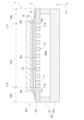
- FIG. 1 is a plan view of an electrolysis cell according to an embodiment.
- FIG. 2 is a cross-sectional view taken along line AA of FIG.
- Fig. 1 is a plan view of an electrolytic cell 1 according to an embodiment.
- Fig. 2 is a cross-sectional view taken along line AA in Fig. 1.
- the electrolytic cell 1 is an example of the "electrochemical cell" according to the present invention.
- the electrolytic cell 1 is formed in a plate shape extending in the X-axis and Y-axis directions.
- the electrolytic cell 1 is formed in a rectangular shape extending in the Y-axis direction in a plan view.
- the planar shape of the electrolytic cell 1 is not particularly limited, and may be a polygon other than a rectangle, an ellipse, a circle, etc.
- the X-axis and Y-axis directions are each an example of a surface direction.
- the electrolysis cell 1 includes a metal support 10, a cell body 20, and a flow path member 30.
- the metal support 10 supports the cell main body 20.
- the metal support 10 is formed in a plate shape.
- the metal support 10 may be in a flat plate shape or a curved plate shape.
- the metal support 10 may have any thickness as long as it can support the electrolysis cell 1, and the thickness is not particularly limited, but may be, for example, 0.1 mm or more and 2.0 mm or less.
- the metal support 10 has a plurality of communication holes 11, a first main surface 12, and a second main surface 13.
- Each communication hole 11 penetrates the metal support 10 from the first main surface 12 to the second main surface 13. Each communication hole 11 opens to the first main surface 12 and the second main surface 13. The opening of each communication hole 11 on the first main surface 12 side is covered by the hydrogen electrode layer 6. The opening of each communication hole 11 on the second main surface 13 side is connected to a flow path 30a described later.
- Each communication hole 11 can be formed by mechanical processing (e.g., punching), laser processing, or chemical processing (e.g., etching).
- each communication hole 11 may be a communication hole in which open pores of the porous metal are connected.
- Each communication hole 11 may be perpendicular to the first main surface 12, or may not be perpendicular to the first main surface 12, and may not be linear.
- the cell body 20 is joined to the first main surface 12.
- the flow path member 30 is joined to the second main surface 13.
- the first main surface 12 is provided on the opposite side of the second main surface 13.
- the metal support 10 has a gas permeable region 10a and a gas non-permeable region 10b.
- the gas permeable region 10a is a region of the metal support 10 in which a plurality of communication holes 11 are formed.
- the gas non-permeable region 10b is a region of the metal support 10 other than the gas permeable region 10a.
- the gas non-permeable region 10b surrounds the gas permeable region 10a in a plan view from the Z-axis direction perpendicular to the X-axis and Y-axis directions. Therefore, as shown in FIG. 2, in a cross section of the metal support 10 along the Z-axis direction, the gas non-permeable region 10b appears on both sides of the gas permeable region 10a.
- the boundary between the gas permeable region 10a and the gas non-permeable region 10b is defined by the openings of the first and second communication holes 11a and 11b located at the outermost positions in the X-axis direction.
- the boundary between the gas permeable region 10a and the gas non-permeable region 10b is defined by a first reference line 11S and a second reference line 11T.
- the first reference line 11S is a straight line that passes through the outermost position P1 in the X-axis direction of the opening on the first main surface 12 side of the first communication hole 11a located at the outermost position in the X-axis direction and is parallel to the Z-axis direction (perpendicular to the first main surface 12 in FIG. 2).
- the second reference line 11T is a straight line that passes through the outermost position P2 in the X-axis direction of the opening on the first main surface 12 side of the second supply hole 11b located at the farthest position from the first supply hole 11a in the X-axis direction and is parallel to the Z-axis direction (perpendicular to the first main surface 12 in FIG. 2).
- the area of the metal support 10 between the first reference line 11S and the second reference line 11T is the gas permeable area 10a, and the areas of the metal support 10 excluding the gas permeable area 10a, i.e., the areas on both sides of the gas permeable area 10a, are the gas non-permeable areas 10b.
- the metal support 10 is made of a metal material.
- the metal support 10 is made of an alloy material containing Cr (chromium).
- Examples of such metal materials include Fe-Cr alloy steel (stainless steel, etc.) and Ni-Cr alloy steel.
- Cr content in the metal support 10 can be 4% by mass or more and 30% by mass or less.
- the metal support 10 may contain Ti (titanium) and Zr (zirconium).
- the Ti content in the metal support 10 is not particularly limited, but may be 0.01 mol% or more and 1.0 mol% or less.
- the Al content in the metal support 10 is not particularly limited, but may be 0.01 mol% or more and 0.4 mol% or less.
- the metal support 10 may contain Ti as TiO2 (titania) and Zr as ZrO2 (zirconia).
- the metal support 10 may have an oxide film on its surface, which is formed by oxidation of the constituent elements of the metal support 10.
- a typical example of the oxide film is a chromium oxide film.
- the chromium oxide film covers at least a portion of the surface of the metal support 10.
- the chromium oxide film may also cover at least a portion of the inner wall surface of each communication hole 11.
- the cell body 20 is disposed on the metal support 10.
- the cell body 20 has a hydrogen electrode layer 6 (cathode), an electrolyte layer 7, a reaction prevention layer 8, and an oxygen electrode layer 9 (anode).
- the hydrogen electrode layer 6, electrolyte layer 7, reaction prevention layer 8, and oxygen electrode layer 9 are stacked in this order from the metal support 10 side in the Z-axis direction perpendicular to the X-axis direction and the Y-axis direction.
- the hydrogen electrode layer 6, electrolyte layer 7, and oxygen electrode layer 9 are required components, while the reaction prevention layer 8 is optional.
- the hydrogen electrode layer 6 is formed on the metal support 10.
- the hydrogen electrode layer 6 is disposed between the metal support 10 and the electrolyte layer 7.
- the hydrogen electrode layer 6 is supported by the metal support 10.
- the hydrogen electrode layer 6 is disposed on a first main surface 12 of the metal support 10.
- the hydrogen electrode layer 6 is an example of a "first electrode layer" according to the present invention.
- a source gas is supplied to the hydrogen electrode layer 6 through each of the communication holes 11.
- the source gas contains at least H2O .
- the hydrogen electrode layer 6 produces H 2 from the source gas in accordance with the electrochemical reaction of water electrolysis shown in the following formula (1).
- Hydrogen electrode layer 6 H 2 O+2e ⁇ ⁇ H 2 +O 2 ⁇ (1)
- the hydrogen electrode layer 6 produces H 2 , CO, and O 2 ⁇ from the source gas in accordance with the co-electrochemical reactions shown in the following formulas (2), (3), and (4).
- Hydrogen electrode layer 6 CO 2 + H 2 O + 4e ⁇ ⁇ CO + H 2 + 2O 2 ⁇ (2) Electrochemical reaction of H 2 O: H 2 O + 2e ⁇ ⁇ H 2 + O 2 ⁇ (3) Electrochemical reaction of CO2 : CO2 + 2e- ⁇ CO + O2 -... (4)
- the hydrogen electrode layer 6 is a porous body having electronic conductivity.
- the hydrogen electrode layer 6 contains nickel (Ni).
- Ni functions as an electronic conductor and also functions as a thermal catalyst that promotes a thermal reaction between the generated H 2 and CO 2 contained in the raw material gas to maintain an appropriate gas composition for methanation, reverse water gas shift reaction, etc.
- the Ni contained in the hydrogen electrode layer 6 is basically present in the form of metallic Ni during operation of the electrolysis cell 1, but may also be partially present in the form of nickel oxide (NiO).
- the hydrogen electrode layer 6 may contain an ion-conductive material such as YSZ, CSZ, ScSZ, GDC, SDC , (La, Sr)(Cr, Mn) O3 , (La, Sr) TiO3 , Sr2 (Fe, Mo) 2O6 , (La, Sr) VO3 , (La, Sr) FeO3 , LDC (lanthanum-doped ceria), LSGM (lanthanum gallate), or a mixture of two or more of these materials.
- an ion-conductive material such as YSZ, CSZ, ScSZ, GDC, SDC , (La, Sr)(Cr, Mn) O3 , (La, Sr) TiO3 , Sr2 (Fe, Mo) 2O6 , (La, Sr) VO3 , (La, Sr) FeO3 , LDC (lanthanum-doped ceria), LSGM (lanthanum gallate
- the Ni content in the hydrogen electrode layer 6 is not particularly limited, but can be 20 vol% or more and 50 vol% or less.
- the Ni content is calculated by the following method. First, a cross section of the hydrogen electrode layer 6 along the Z-axis direction is exposed. Next, a Ni composition mapping image of the cross section of the hydrogen electrode layer 6 is obtained at 5,000 to 10,000 times magnification using an SEM device (FE-SEM JSM-7900F manufactured by JEOL Ltd.) and an EDS device (JED-2300) attached to the SEM device. Next, Ni particles are identified in the Ni composition mapping image by binarizing the image using image analysis software Image-Pro manufactured by MEDIACYBERNETICS. The Ni content in the hydrogen electrode layer 6 is calculated by dividing the total area of the Ni particles by the total area (including pores) of the hydrogen electrode layer 6 in the backscattered electron image.
- the content of the ion conductive material in the hydrogen electrode layer 6 is not particularly limited, but can be 20 vol% or more and 50 vol% or less.
- the content of the ion conductive material is calculated by the following method. First, using the above-mentioned SEM device and EDS device, a composition mapping image of the element with the largest content (hereinafter referred to as the "most abundant element") among the constituent elements of the ion conductive material in the cross section of the hydrogen electrode layer 6 is obtained at 5,000 to 10,000 times magnification. Next, using the above-mentioned image analysis software Image-Pro, the particle portion of the most abundant element is identified in the composition mapping image of the most abundant element by binarizing the image using image analysis. Then, the content of the ion conductive material in the hydrogen electrode layer 6 is calculated by dividing the total area of the particle portions of the most abundant element by the total area (including pores) of the hydrogen electrode layer 6 in the backscattered electron image.
- the thickness of the hydrogen electrode layer 6 is not particularly limited, but can be, for example, 1 ⁇ m or more and 100 ⁇ m or less.
- the hydrogen electrode layer 6 has a first region 6a and a second region 6b.
- the first region 6a is a region of the hydrogen electrode layer 6 that is formed on the gas permeable region 10a of the metal support 10.
- the second region 6b is a region of the hydrogen electrode layer 6 that is formed on the gas non-permeable region 10b of the metal support 10.
- the second region 6b surrounds the first region 6a when viewed in a plan view from the Z-axis direction. Therefore, as shown in FIG. 2, in a cross section of the hydrogen electrode layer 6 along the Z-axis direction, the second region 6b appears on both sides of the first region 6a.
- the boundary between the first region 6a and the second region 6b is defined by the first reference line 11S and the second reference line 11T described above.
- the region of the hydrogen electrode layer 6 between the first reference line 11S and the second reference line 11T is the first region 6a, and the region of the hydrogen electrode layer 6 excluding the first region 6a, i.e., the regions on both sides of the first region 6a, is the second region 6b.
- the activity of Ni contained in the second region 6b is higher than that of Ni contained in the first region 6a.
- the second region 6b has a low electrode activity due to a temperature drop caused by heat dissipation, so the H2 generation rate is low and the H2O concentration is likely to be high.
- the H2O concentration is high, the growth rate of the oxide film on the surface of the metal support 10 increases, making it difficult for current to flow through the second region 6b and increasing the current distribution.
- the electrode activity can be improved by reducing the average particle size of Ni in the second region 6b. As a result, the H2 generation rate is maintained, and the increase in the current distribution can be suppressed.
- the temperature of the second region 6b is likely to decrease.
- the function of Ni as a thermal catalyst can be improved by reducing the average particle size of Ni. Therefore, the above-mentioned effects are particularly effective in the electrolytic cell 1.
- the average particle size of Ni contained in the first region 6a is not particularly limited, but can be 3 ⁇ m or more and 10 ⁇ m or less.
- the average particle size of Ni contained in the second region 6b is not particularly limited, but can be 1 ⁇ m or more and 7 ⁇ m or less.
- the average particle size of Ni contained in the first region 6a is calculated by the following method. First, a cross section of the hydrogen electrode layer 6 along the Z-axis direction is exposed. Next, using an SEM device (FE-SEM JSM-7900F manufactured by JEOL Ltd.) and an EDS device (JED-2300) attached to the SEM device, Ni mapping images are obtained at 5,000 to 10,000 times magnification at three locations: an arbitrary position on the first communication hole 11a, an arbitrary position on the second communication hole 11b, and the center of the first region 6a in the surface direction, and at five locations that divide the first region 6a into six equal parts in the thickness direction. This results in 15 Ni mapping images.
- SEM device FE-SEM JSM-7900F manufactured by JEOL Ltd.
- JED-2300 EDS device
- Ni particle portions are identified in each Ni mapping image by performing binarization processing through image analysis. This results in 15 analysis images.
- the diameter of a circle having the same area as the area of each Ni is obtained as the particle size of each Ni.
- the Ni particle sizes obtained from the 15 analysis images are then arithmetically averaged to calculate the average particle size of Ni contained in the first region 6a.
- the thickness direction is the direction perpendicular to the surface direction parallel to the first main surface 12 of the metal support 10.
- an approximation straight line of the first main surface 12 obtained by the least squares method in the cross section of the metal support 10 along the Z-axis direction is used.
- the average grain size of Ni contained in the second region 6b is calculated by the same method as the average grain size of Ni contained in the first region 6a.
- Ni mapping images are obtained at two locations that divide each of the second regions 6b located on both sides of the first region 6a into thirds in the surface direction, and at five locations that divide the second region 6b into six in the thickness direction. Therefore, 20 Ni mapping images are used to calculate the average grain size of Ni contained in the second region 6b.
- the 20 Ni mapping images are obtained on the cross section of the hydrogen electrode layer 6 used to calculate the average grain size of Ni contained in the first region 6a.
- the porosity of the second region 6b is preferably greater than that of the first region 6a. This improves gas diffusion in the second region 6b, where raw material gas is less likely to be supplied from the communication holes 11, and further improves the electrode reaction in the second region 6b. This further reduces current distribution between the first region 6a and the second region 6b, thereby further suppressing deterioration of the first electrode layer 6.
- the porosity of the first region 6a is not particularly limited, but can be 20% or more and 40% or less.
- the porosity of the second region 6b is not particularly limited, but can be 25% or more and 50% or less.
- the porosity of the first region 6a is calculated by the following method. First, a cross section of the hydrogen electrode layer 6 along the Z-axis direction is exposed. Next, using the SEM device, a backscattered electron image of the cross section of the first region 6a is obtained at 10,000x magnification. Next, using image analysis software Image-Pro made by MEDIACYBERNETICS, the areas displayed in black in the backscattered electron image (corresponding to pores) are identified. The porosity of the first region 6a is then calculated by dividing the total area of the pores by the total area of the backscattered electron images of the first region 6a.
- the porosity of the second region 6b is calculated by dividing the total area of the pores by the total area of the backscattered electron image of the second region 6b, similar to the porosity of the first region 6a.
- the hydrogen electrode layer 6 is produced by forming a first region 6a on the metal support 10 using a constituent material for the first region, and then forming a second region 6b surrounding the first region 6a using a constituent material for the second region.
- the method for forming the first and second regions 6a, 6b may be a sintering method, a spray coating method (thermal spraying, aerosol deposition, aerosol gas deposition, powder jet deposition, particle jet deposition, cold spray, etc.), a PVD method (sputtering, pulsed laser deposition, etc.), a CVD method, etc.
- the electrolyte layer 7 is disposed between the hydrogen electrode layer 6 and the oxygen electrode layer 9.
- the reaction prevention layer 8 is disposed between the electrolyte layer 7 and the oxygen electrode layer 9, and therefore the electrolyte layer 7 is disposed between the hydrogen electrode layer 6 and the reaction prevention layer 8 and is connected to both the hydrogen electrode layer 6 and the reaction prevention layer 8.
- the electrolyte layer 7 covers the hydrogen electrode layer 6 and also covers the area of the first main surface 12 of the metal support 10 that is exposed from the hydrogen electrode layer 6.
- the electrolyte layer 7 transfers O 2- generated in the hydrogen electrode layer 6 to the oxygen electrode layer 9.
- the electrolyte layer 7 is made of a dense material having oxide ion conductivity.
- the electrolyte layer 7 can be made of, for example, YSZ (yttria-stabilized zirconia, e.g., 8YSZ), GDC (gadolinium-doped ceria), ScSZ (scandia-stabilized zirconia), SDC (samarium-doped ceria), LSGM (lanthanum gallate), or the like.
- the porosity of the electrolyte layer 7 is not particularly limited, but can be, for example, 0.1% to 7%.
- the thickness of the electrolyte layer 7 is not particularly limited, but can be, for example, 1 ⁇ m to 100 ⁇ m.
- the method for forming the electrolyte layer 7 is not particularly limited, and methods such as baking, spray coating, PVD, and CVD can be used.
- reaction prevention layer 8 The reaction prevention layer 8 is disposed between the electrolyte layer 7 and the oxygen electrode layer 9. The reaction prevention layer 8 is disposed on the opposite side of the electrolyte layer 7 to the hydrogen electrode layer 6. The reaction prevention layer 8 prevents the constituent elements of the electrolyte layer 7 from reacting with the constituent elements of the oxygen electrode layer 9 to form a layer with high electrical resistance.
- the reaction prevention layer 8 is made of an oxide ion conductive material.
- the reaction prevention layer 8 can be made of GDC, SDC, etc.
- the porosity of the reaction prevention layer 8 is not particularly limited, but can be, for example, 0.1% to 50%.
- the thickness of the reaction prevention layer 8 is not particularly limited, but can be, for example, 1 ⁇ m to 50 ⁇ m.
- the method for forming the reaction prevention layer 8 is not particularly limited, and a baking method, a spray coating method, a PVD method, a CVD method, etc. can be used.
- the oxygen electrode layer 9 is disposed on the opposite side of the hydrogen electrode layer 6 with respect to the electrolyte layer 7.
- the reaction prevention layer 8 is disposed between the electrolyte layer 7 and the oxygen electrode layer 9, and therefore the oxygen electrode layer 9 is connected to the reaction prevention layer 8. If the reaction prevention layer 8 is not disposed between the electrolyte layer 7 and the oxygen electrode layer 9, the oxygen electrode layer 9 is connected to the electrolyte layer 7.
- the oxygen electrode layer 9 is an example of a "second electrode layer" according to the present invention.
- the oxygen electrode layer 9 produces O 2 from O 2 ⁇ transferred from the hydrogen electrode layer 6 via the electrolyte layer 7 in accordance with the chemical reaction of the following formula (2).
- Oxygen electrode layer 9 2O 2 ⁇ ⁇ O 2 +4e ⁇ (2)
- the oxygen electrode layer 9 is made of a porous material having oxide ion conductivity and electron conductivity, and may be made of a composite material of one or more of (La,Sr)(Co,Fe) O3 , (La,Sr) FeO3 , La(Ni,Fe) O3 , (La,Sr) CoO3 , and (Sm,Sr) CoO3 and an oxide ion conductive material (such as GDC).
- the porosity of the oxygen electrode layer 9 is not particularly limited, but can be, for example, 20% or more and 60% or less.
- the thickness of the oxygen electrode layer 9 is not particularly limited, but can be, for example, 1 ⁇ m or more and 100 ⁇ m or less.
- the method for forming the oxygen electrode layer 9 is not particularly limited, and a firing method, a spray coating method, a PVD method, a CVD method, etc. can be used.
- the flow path member 30 is joined to the second main surface 13 of the metal support 10.
- the flow path member 30 forms a flow path 30a between itself and the metal support 10.
- a source gas is supplied to the flow path 30a.
- the source gas supplied to the flow path 30a is supplied to the hydrogen electrode layer 6 of the cell main body 20 through each communication hole 11 of the metal support 10.
- the flow path member 30 can be made of, for example, an alloy material.
- the flow path member 30 may be made of the same material as the metal support 10. In this case, the flow path member 30 may be substantially integral with the metal support 10.
- the flow path member 30 has a frame body 31 and an interconnector 32.
- the frame body 31 is an annular member that surrounds the side of the flow path 30a.
- the frame body 31 is joined to the second main surface 13 of the metal support body 10.
- the interconnector 32 is a plate-shaped member for electrically connecting an external power source or another electrolysis cell in series with the electrolysis cell 1.
- the interconnector 32 is joined to the frame body 31.
- the frame body 31 and the interconnector 32 are separate members, but the frame body 31 and the interconnector 32 may be an integrated member.
- a part of the hydrogen electrode layer 6 may extend into each of the communicating holes 11 of the metal support 10.
- the first region 6a of the hydrogen electrode layer 6 described in the above embodiment is a region of the hydrogen electrode layer 6 formed on the gas permeable region 10a of the metal support 10. Therefore, the region of the hydrogen electrode layer 6 extending into the communicating holes 11 is not included in the second region 6b of the hydrogen electrode layer 6.
- the average grain size of Ni contained in the second region 6b is smaller than the average grain size of Ni contained in the first region 6a in one cross section of the hydrogen electrode layer 6.
- Such a configuration is preferably observed in all cross sections of the hydrogen electrode layer 6, it is sufficient if it is observed in at least one cross section of the hydrogen electrode layer 6. This is because, if it is observed in even one cross section, deterioration of the hydrogen electrode layer 6 can be suppressed at least in that location.
- the electrolysis cell 1 has been described as an example of an electrochemical cell, but the electrochemical cell is not limited to the electrolysis cell.
- An electrochemical cell is a general term for an element in which a pair of electrodes are arranged so that an electromotive force is generated from an overall oxidation-reduction reaction in order to convert electrical energy into chemical energy, and an element for converting chemical energy into electrical energy. Therefore, the electrochemical cell includes, for example, a fuel cell that uses oxide ions or protons as a carrier.
- Electrolysis cell 10
- Metal support 11 Through hole 12
- First main surface 12
- Second main surface 20
- Cell body 6
- Hydrogen electrode layer 7
- Electrolyte layer 8
- Reaction prevention layer 9
- Oxygen electrode layer 30
- Flow path member 30a Flow path
Landscapes
- Chemical & Material Sciences (AREA)
- Engineering & Computer Science (AREA)
- Chemical Kinetics & Catalysis (AREA)
- Electrochemistry (AREA)
- Materials Engineering (AREA)
- Metallurgy (AREA)
- Organic Chemistry (AREA)
- Inorganic Chemistry (AREA)
- Electrolytic Production Of Non-Metals, Compounds, Apparatuses Therefor (AREA)
- Fuel Cell (AREA)
Abstract
Description
図1は、実施形態に係る電解セル1の平面図である。図2は、図1のA-A断面図である。電解セル1は、本発明に係る「電気化学セル」の一例である。
金属支持体10は、セル本体部20を支持する。金属支持体10は、板状に形成される。金属支持体10は、平板状であってもよいし、曲板状であってもよい。金属支持体10は電解セル1を支持できればよく、その厚みは特に制限されないが、例えば0.1mm以上2.0mm以下とすることができる。
セル本体部20は、金属支持体10上に配置される。セル本体部20は、水素極層6(カソード)、電解質層7、反応防止層8、及び酸素極層9(アノード)を有する。
水素極層6は、金属支持体10上に形成される。水素極層6は、金属支持体10及び電解質層7の間に配置される。水素極層6は、金属支持体10によって支持される。詳細には、水素極層6は、金属支持体10の第1主面12上に配置される。水素極層6は、本発明に係る「第1電極層」の一例である。
・H2Oの電気化学反応:H2O+2e-→H2+O2-・・・(3)
・CO2の電気化学反応:CO2+2e-→CO+O2-・・・(4)
電解質層7は、水素極層6及び酸素極層9の間に配置される。本実施形態では、電解質層7及び酸素極層9の間に反応防止層8が配置されているので、電解質層7は、水素極層6及び反応防止層8の間に配置され、水素極層6及び反応防止層8それぞれに接続される。
反応防止層8は、電解質層7及び酸素極層9の間に配置される。反応防止層8は、電解質層7を基準として水素極層6の反対側に配置される。反応防止層8は、電解質層7の構成元素が酸素極層9の構成元素と反応して電気抵抗の大きい層が形成されることを抑制する。
酸素極層9は、電解質層7を基準として水素極層6の反対側に配置される。本実施形態では、電解質層7及び酸素極層9の間に反応防止層8が配置されているので、酸素極層9は反応防止層8に接続される。電解質層7及び酸素極層9の間に反応防止層8が配置されない場合、酸素極層9は電解質層7に接続される。酸素極層9は、本発明に係る「第2電極層」の一例である。
流路部材30は、金属支持体10の第2主面13に接合される。流路部材30は、金属支持体10との間に流路30aを形成する。流路30aには、原料ガスが供給される。流路30aに供給された原料ガスは、金属支持体10の各連通孔11を介して、セル本体部20の水素極層6に供給される。
以上、本発明の実施形態について説明したが、本発明はこれらに限定されるものではなく、本発明の趣旨を逸脱しない限りにおいて種々の変更が可能である。
水素極層6の一部は、金属支持体10の各連通孔11に入り込んでいてもよい。ただし、上記実施形態にて説明した水素極層6の第1領域6aは、水素極層6のうち金属支持体10のガス透過領域10a上に形成された領域である。従って、水素極層6のうち連通孔11に入り込んだ領域は、水素極層6の第2領域6bには含まれない。
上記実施形態では、水素極層6の一断面において、第2領域6bが含有するNiの平均粒径は、第1領域6aが含有するNiの平均粒径より小さいことを説明した。このような構成は、水素極層6の全ての断面において観察されることが好ましいが、水素極層6の少なくとも一断面において観察できればよい。一断面であっても観察されるのであれば、少なくとも当該箇所では水素極層6の劣化を抑制できるからである。
上記実施形態では、電気化学セルの一例として電解セル1について説明したが、電気化学セルは電解セルに限られない。電気化学セルとは、電気エネルギーを化学エネルギーに変えるため、全体的な酸化還元反応から起電力が生じるように一対の電極が配置された素子と、化学エネルギーを電気エネルギーに変えるための素子との総称である。従って、電気化学セルには、例えば、酸化物イオン或いはプロトンをキャリアとする燃料電池が含まれる。
10 金属支持体
11 連通孔
12 第1主面
13 第2主面
20 セル本体部
6 水素極層
7 電解質層
8 反応防止層
9 酸素極層
30 流路部材
30a 流路
Claims (3)
- 複数の連通孔が形成されたガス透過領域と、平面視において前記ガス透過領域を取り囲むガス非透過領域とを有する金属支持体と、
前記金属支持体上に配置されたセル本体部と、
を備え、
前記セル本体部は、
Niを含有する第1電極層と、
第2電極層と、
前記第1電極層及び前記第2電極層の間に配置される電解質層と、
を有し、
前記第1電極層は、前記ガス透過領域上に形成される第1領域と、前記ガス非透過領域上に形成される第2領域とを有し、
前記第2領域が含有するNiの平均粒径は、前記第1領域が含有するNiの平均粒径より小さい、
電気化学セル。 - 前記第2領域の気孔率は、前記第1領域の気孔率より大きい、
請求項1に記載の電気化学セル。 - 前記第1電極層は、H2Oを含む原料ガスからH2を生成する水素極である、
請求項1又は2に記載の電気化学セル。
Priority Applications (5)
| Application Number | Priority Date | Filing Date | Title |
|---|---|---|---|
| DE112023000206.1T DE112023000206T5 (de) | 2023-03-24 | 2023-03-24 | Elektrochemische Zelle |
| JP2024514722A JP7696497B2 (ja) | 2023-03-24 | 2023-03-24 | 電気化学セル |
| PCT/JP2023/011859 WO2024201575A1 (ja) | 2023-03-24 | 2023-03-24 | 電気化学セル |
| CN202380013570.1A CN120858201A (zh) | 2023-03-24 | 2023-03-24 | 电化学单电池 |
| US18/616,626 US20240318330A1 (en) | 2023-03-24 | 2024-03-26 | Electrochemical cell |
Applications Claiming Priority (1)
| Application Number | Priority Date | Filing Date | Title |
|---|---|---|---|
| PCT/JP2023/011859 WO2024201575A1 (ja) | 2023-03-24 | 2023-03-24 | 電気化学セル |
Related Child Applications (1)
| Application Number | Title | Priority Date | Filing Date |
|---|---|---|---|
| US18/616,626 Continuation US20240318330A1 (en) | 2023-03-24 | 2024-03-26 | Electrochemical cell |
Publications (1)
| Publication Number | Publication Date |
|---|---|
| WO2024201575A1 true WO2024201575A1 (ja) | 2024-10-03 |
Family
ID=92803984
Family Applications (1)
| Application Number | Title | Priority Date | Filing Date |
|---|---|---|---|
| PCT/JP2023/011859 Ceased WO2024201575A1 (ja) | 2023-03-24 | 2023-03-24 | 電気化学セル |
Country Status (5)
| Country | Link |
|---|---|
| US (1) | US20240318330A1 (ja) |
| JP (1) | JP7696497B2 (ja) |
| CN (1) | CN120858201A (ja) |
| DE (1) | DE112023000206T5 (ja) |
| WO (1) | WO2024201575A1 (ja) |
Citations (5)
| Publication number | Priority date | Publication date | Assignee | Title |
|---|---|---|---|---|
| JP2012069420A (ja) * | 2010-09-24 | 2012-04-05 | Dainippon Printing Co Ltd | 固体酸化物形燃料電池 |
| JP2018133165A (ja) * | 2017-02-14 | 2018-08-23 | 日本特殊陶業株式会社 | 電気化学反応単セルおよび電気化学反応セルスタック |
| WO2018198352A1 (ja) * | 2017-04-28 | 2018-11-01 | 株式会社 東芝 | 固体酸化物電気化学セル及びその製造方法 |
| WO2018216159A1 (ja) * | 2017-05-25 | 2018-11-29 | 日産自動車株式会社 | 燃料電池セル |
| WO2019026138A1 (ja) * | 2017-07-31 | 2019-02-07 | 日産自動車株式会社 | 燃料電池セル |
Family Cites Families (1)
| Publication number | Priority date | Publication date | Assignee | Title |
|---|---|---|---|---|
| JP6757434B1 (ja) | 2019-03-20 | 2020-09-16 | 日本碍子株式会社 | 電気化学セル |
-
2023
- 2023-03-24 CN CN202380013570.1A patent/CN120858201A/zh active Pending
- 2023-03-24 WO PCT/JP2023/011859 patent/WO2024201575A1/ja not_active Ceased
- 2023-03-24 JP JP2024514722A patent/JP7696497B2/ja active Active
- 2023-03-24 DE DE112023000206.1T patent/DE112023000206T5/de active Pending
-
2024
- 2024-03-26 US US18/616,626 patent/US20240318330A1/en active Pending
Patent Citations (5)
| Publication number | Priority date | Publication date | Assignee | Title |
|---|---|---|---|---|
| JP2012069420A (ja) * | 2010-09-24 | 2012-04-05 | Dainippon Printing Co Ltd | 固体酸化物形燃料電池 |
| JP2018133165A (ja) * | 2017-02-14 | 2018-08-23 | 日本特殊陶業株式会社 | 電気化学反応単セルおよび電気化学反応セルスタック |
| WO2018198352A1 (ja) * | 2017-04-28 | 2018-11-01 | 株式会社 東芝 | 固体酸化物電気化学セル及びその製造方法 |
| WO2018216159A1 (ja) * | 2017-05-25 | 2018-11-29 | 日産自動車株式会社 | 燃料電池セル |
| WO2019026138A1 (ja) * | 2017-07-31 | 2019-02-07 | 日産自動車株式会社 | 燃料電池セル |
Also Published As
| Publication number | Publication date |
|---|---|
| US20240318330A1 (en) | 2024-09-26 |
| JPWO2024201575A1 (ja) | 2024-10-03 |
| JP7696497B2 (ja) | 2025-06-20 |
| DE112023000206T5 (de) | 2024-12-19 |
| CN120858201A (zh) | 2025-10-28 |
Similar Documents
| Publication | Publication Date | Title |
|---|---|---|
| US20210111415A1 (en) | Electrochemical Element Stack, Electrochemical Element, Electrochemical Module, Electrochemical Device, and Energy System | |
| US20240332566A1 (en) | Electrochemical cell | |
| US20240332565A1 (en) | Electrochemical cell | |
| JP7280991B1 (ja) | 電気化学セル | |
| JP7696497B2 (ja) | 電気化学セル | |
| WO2023176241A1 (ja) | 電気化学セル | |
| JP7657365B2 (ja) | 電気化学セル | |
| JP7692539B2 (ja) | 電気化学セル | |
| JP7649929B2 (ja) | 電気化学セル | |
| JP7649810B2 (ja) | 電気化学セル | |
| JP7657379B1 (ja) | 電気化学セル | |
| JP7659705B1 (ja) | 電気化学セル | |
| JP7625134B2 (ja) | 電気化学セル | |
| JP7577244B2 (ja) | 電気化学セル | |
| JP7668971B2 (ja) | 電気化学セル | |
| JP7698795B2 (ja) | 電気化学セル | |
| JP7604715B2 (ja) | 電気化学セル | |
| JP7618109B1 (ja) | インターコネクタ、及び電気化学セル | |
| JP7394189B1 (ja) | 電気化学セル | |
| US20250263852A1 (en) | Electrochemical cell | |
| WO2025191855A1 (ja) | 電解セル及び燃料電池セル | |
| WO2025191865A1 (ja) | 電解セル | |
| WO2024143292A1 (ja) | 電気化学セル | |
| WO2024201667A1 (ja) | 電解セル | |
| WO2024201640A1 (ja) | 電気化学セル |
Legal Events
| Date | Code | Title | Description |
|---|---|---|---|
| WWE | Wipo information: entry into national phase |
Ref document number: 2024514722 Country of ref document: JP |
|
| WWE | Wipo information: entry into national phase |
Ref document number: 202380013570.1 Country of ref document: CN |
|
| WWE | Wipo information: entry into national phase |
Ref document number: 112023000206 Country of ref document: DE |
|
| 121 | Ep: the epo has been informed by wipo that ep was designated in this application |
Ref document number: 23930216 Country of ref document: EP Kind code of ref document: A1 |
|
| WWP | Wipo information: published in national office |
Ref document number: 202380013570.1 Country of ref document: CN |
|
| 122 | Ep: pct application non-entry in european phase |
Ref document number: 23930216 Country of ref document: EP Kind code of ref document: A1 |