WO2024201557A1 - 算出装置およびコンピュータ読み取り可能な記憶媒体 - Google Patents
算出装置およびコンピュータ読み取り可能な記憶媒体 Download PDFInfo
- Publication number
- WO2024201557A1 WO2024201557A1 PCT/JP2023/011727 JP2023011727W WO2024201557A1 WO 2024201557 A1 WO2024201557 A1 WO 2024201557A1 JP 2023011727 W JP2023011727 W JP 2023011727W WO 2024201557 A1 WO2024201557 A1 WO 2024201557A1
- Authority
- WO
- WIPO (PCT)
- Prior art keywords
- axis
- value
- coordinate system
- deviation
- position deviation
- Prior art date
- Legal status (The legal status is an assumption and is not a legal conclusion. Google has not performed a legal analysis and makes no representation as to the accuracy of the status listed.)
- Ceased
Links
Images







Classifications
-
- G—PHYSICS
- G05—CONTROLLING; REGULATING
- G05B—CONTROL OR REGULATING SYSTEMS IN GENERAL; FUNCTIONAL ELEMENTS OF SUCH SYSTEMS; MONITORING OR TESTING ARRANGEMENTS FOR SUCH SYSTEMS OR ELEMENTS
- G05B19/00—Program-control systems
- G05B19/02—Program-control systems electric
- G05B19/18—Numerical control [NC], i.e. automatically operating machines, in particular machine tools, e.g. in a manufacturing environment, so as to execute positioning, movement or co-ordinated operations by means of program data in numerical form
-
- G—PHYSICS
- G05—CONTROLLING; REGULATING
- G05B—CONTROL OR REGULATING SYSTEMS IN GENERAL; FUNCTIONAL ELEMENTS OF SUCH SYSTEMS; MONITORING OR TESTING ARRANGEMENTS FOR SUCH SYSTEMS OR ELEMENTS
- G05B2219/00—Program-control systems
- G05B2219/30—Nc systems
- G05B2219/50—Machine tool, machine tool null till machine tool work handling
- G05B2219/50216—Synchronize speed and position of several axis, spindles
Definitions
- the present disclosure relates to a computing device and a computer-readable storage medium.
- the calculation device disclosed herein includes an acquisition unit that acquires a first value indicating the position deviation of the master axis and a second value indicating the position deviation of a slave axis that is disposed at an inclination of a predetermined angle with respect to the master axis, a conversion unit that performs at least one of converting the first value acquired by the acquisition unit into a third value indicating the position deviation of the master axis in a predetermined coordinate system and converting the second value acquired by the acquisition unit into a fourth value indicating the position deviation of the slave axis in the predetermined coordinate system, a calculation unit that calculates the amount of deviation between the position deviation of the master axis and the position deviation of the slave axis in the predetermined coordinate system based on the first value and the fourth value, the second value and the third value, or the third value and the fourth value, and an output unit that outputs the amount of deviation calculated by the calculation unit.
- the computer-readable storage medium of the present disclosure stores instructions that cause a computer to perform at least one of the following: acquiring a first value indicating the position deviation of the master axis and a second value indicating the position deviation of a slave axis that is disposed at an inclination of a predetermined angle with respect to the master axis; converting the acquired first value into a third value indicating the position deviation of the master axis in a predetermined coordinate system; and converting the acquired second value into a fourth value indicating the position deviation of the slave axis in the predetermined coordinate system; calculating the amount of deviation between the position deviation of the master axis and the position deviation of the slave axis in the predetermined coordinate system based on the first value and the fourth value, the second value and the third value, or the third value and the fourth value; and outputting the calculated amount of deviation.
- FIG. 1 is a diagram illustrating an example of a system including a calculation device.
- FIG. 2 is a block diagram illustrating an example of a hardware configuration of a calculation device.
- FIG. 2 is a block diagram illustrating an example of the functions of the calculation device.
- FIG. 13 is a diagram for explaining the inclination of a control axis.
- FIG. 11 is a diagram for explaining a position deviation.
- FIG. 11 is a diagram for explaining a position deviation.
- 11A and 11B are diagrams for explaining a position deviation of a tilt axis.
- 11A and 11B are diagrams for explaining a position deviation of a tilt axis.
- FIG. 2 is a diagram for explaining an example of a processing machine.
- FIG. 2 is a diagram for explaining an example of a processing machine.
- FIG. 2 is a diagram for explaining an example of a processing machine.
- FIG. 2 is a diagram for explaining an example of a processing machine.
- 11 is a flowchart illustrating an example of a process executed in the calculation device.
- FIG. 2 is a block diagram showing an example of a hardware configuration of a processing machine. 2 is a block diagram showing an example of functions of a calculation device implemented in a numerical control device;
- FIG. 11 is a flowchart illustrating an example of a process executed in the calculation device.
- based on XX means “based on at least XX,” and includes cases where it is based on other elements in addition to XX. Furthermore, “based on XX” is not limited to cases where XX is used directly, but also includes cases where it is based on XX that has been calculated or processed. "XX” is any element (for example, any information).
- FIG. 1 is a diagram for explaining an example of a system including a calculation device.
- the system includes a calculation device 1 and a processing machine 2.
- the calculation device 1 and the processing machine 2 are connected to each other via a network N.
- the calculation device 1 is a device that calculates the amount of deviation between multiple control axes arranged at angles to each other in the processing machine 2.
- the calculation device 1 is implemented in, for example, a PC (Personal Computer), a server, or a mobile terminal.
- the processing machine 2 is a machine tool, a laser processing machine, or a three-dimensional printer.
- the machine tool is, for example, a machining center, a lathe, or a multi-tasking machine.
- the control axes include, for example, the X-axis, the Y-axis, and the Z-axis. The deviation amount will be explained in detail later.
- the processing machine 2 has multiple systems. In each system, the control axes operate based on a processing program. The control axes in each system operate, for example, in multiple coordinate systems that are different from each other. However, the control axes in each system may also operate in one common coordinate system.
- a processing machine 2 with multiple systems is, for example, a lathe equipped with an upper tool post and a lower tool, or a multi-task machine equipped with multiple spindle heads.
- the processing machine 2 is equipped with a numerical control device 3.
- the numerical control device 3 is a device that controls the processing machine 2.
- the numerical control device 3 controls, for example, the operation of the control axis of the processing machine 2.
- the network N connects the calculation device 1 and the processing machine 2 by wired or wireless connection.
- the network N is, for example, an Internet line or a LAN (Local Area Network).
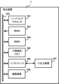
- FIG. 2 is a block diagram showing an example of the hardware configuration of the calculation device 1.
- the calculation device 1 includes, for example, a hardware processor 101, a bus 102, a ROM (Read Only Memory) 103, a RAM (Random Access Memory) 104, a non-volatile memory 105, an interface 106, an input/output device 107, and a communication device 108.
- a hardware processor 101 for example, a hardware processor 101, a bus 102, a ROM (Read Only Memory) 103, a RAM (Random Access Memory) 104, a non-volatile memory 105, an interface 106, an input/output device 107, and a communication device 108.
- ROM Read Only Memory
- RAM Random Access Memory
- the hardware processor 101 is a processor that controls the entire computing device 1 using a system program.
- the hardware processor 101 reads out the system program stored in the ROM 103 via the bus 102.
- the hardware processor 101 is, for example, a CPU (Central Processing Unit) or an electronic circuit.
- the bus 102 is a communication path that connects each piece of hardware in the computing device 1 to each other. Each piece of hardware in the computing device 1 exchanges data via the bus 102.
- ROM 103 is a storage device that stores system programs and the like. ROM 103 is a computer-readable storage medium.
- RAM 104 is a storage device that temporarily stores various data. RAM 104 functions as a working area for the hardware processor 101 to process various data.
- the non-volatile memory 105 is a storage device that retains data even when the power to the calculation device 1 is turned off.
- the non-volatile memory 105 stores, for example, a program for calculating the deviation amount.
- the non-volatile memory 105 is a computer-readable storage medium.
- the non-volatile memory 105 is, for example, a battery-backed memory or an SSD (Solid State Drive).
- the interface 106 connects the bus 102 and the input/output device 107.
- the interface 106 sends, for example, various data processed by the hardware processor 101 to the input/output device 107.
- the input/output device 107 receives various data via the interface 106 and displays the various data on a monitor.
- the input/output device 107 also receives input of various data and sends the data via the interface 106 to, for example, the hardware processor 101.
- the input/output device 107 includes, for example, a monitor, a keyboard, and a mouse.
- the input/output device 107 may be a touch panel.
- the input/output device 107 is, for example, a capacitive touch panel.
- the touch panel is not limited to a capacitive touch panel, and may be a touch panel of another type.
- the communication device 108 is a device for communicating with the processing machine 2 via the network N.
- the communication device 108 transmits and receives data to and from the numerical control device 3 that controls the processing machine 2.
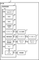
- FIG. 3 is a block diagram showing an example of the functions of the calculation device 1.
- the calculation device 1 includes, for example, an acquisition unit 111, a conversion unit 112, a calculation unit 113, an output unit 114, and a determination unit 115.
- the acquisition unit 111, the conversion unit 112, the calculation unit 113, the output unit 114, and the determination unit 115 are realized, for example, by the hardware processor 101 performing calculation processing using a system program stored in the ROM 103 and a deviation amount calculation program stored in the non-volatile memory 105.
- the acquisition unit 111 acquires a first value indicating the position deviation of the master axis and a second value indicating the position deviation of the slave axis that is arranged at a predetermined angle with respect to the master axis.
- the master axis is a control axis that operates according to commands based on a machining program.
- the master axis is, for example, a control axis included in the first system.
- the slave axis is a control axis that operates based on the commands of the duplicated master axis.
- the slave axis operates, for example, based on a pulse signal that is generated by duplicating the pulse signal for the master axis.
- the master axis and the slave axis are controlled synchronously.
- the slave axis is a control axis that operates by following the master axis.
- the slave axis is, for example, a control axis included in a second system that is different from the first system.
- FIG. 4 is a diagram for explaining the tilt of the control axes. At least one of the slave axis and the master axis is arranged at an incline with respect to the orthogonal axis.
- the orthogonal axes are three axes that are mutually orthogonal.
- the orthogonal axes include, for example, two axes that are mutually orthogonal and arranged horizontally, and one axis that is orthogonal to the two axes.
- the X-axis and the Yi-axis are orthogonal axes.
- the Yi-axis is a virtual axis.
- the Y axis is tilted relative to the horizontally positioned X axis.
- An axis that is tilted relative to an orthogonal axis is called an inclined axis.
- the Y axis is the inclined axis.
- a coordinate system that includes an inclined axis is called an inclined coordinate system.
- the machining program specifies a movement command using coordinate values on orthogonal axes.
- a movement command is specified using coordinate values on the Yi axis, which is orthogonal to the X axis.
- the numerical control device 3 converts the coordinate values on the Yi axis specified in the machining program into coordinate values on the Y axis and moves the structure.
- the numerical control device 3 controls the control axis by converting coordinate values in the orthogonal coordinate system into coordinate values in the tilted coordinate system.
- a orthogonal coordinate system is a coordinate system having three axes that are orthogonal to each other.
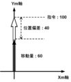
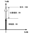
- FIGS. 5A and 5B are diagrams for explaining position deviations. Here, position deviations of orthogonal axes are explained. Note that the Xm-axis and Ym-axis in FIG. 5A are the X-axis and Y-axis, respectively, of the master axis belonging to the first system. The Xs-axis and Ys-axis in FIG. 5B are the X-axis and Y-axis, respectively, of the slave axis belonging to the second system.
- the first system includes, for example, a first spindle head.
- the second system includes, for example, a second spindle head.
- Position deviation is the difference between the command value and the actual movement of a structure, such as a spindle head, when the structure is moving along the control axis.
- a movement command is output to move the first spindle head along the Ym axis from position 0 to position 100.
- the movement command is, for example, a pulse signal.
- the first spindle head can only reach position 60 in that control cycle. In other words, there are cases where movement by an amount corresponding to a pulse signal output in a certain control cycle is not executed. In this case, the position deviation of the Ym axis is 40. In other words, the first value indicating the position deviation of the master axis is 40.
- a similar movement command is also output for the Ys axis. That is, a movement command is output to move the second spindle head from position 0 to position 100 along the Ys axis.
- the second spindle head may only reach position 50, for example.
- the position deviation of the Ys axis is 50.
- the second value indicating the position deviation of the slave axis is 50.
- the deviation amount is an amount that indicates the difference between the position deviation of the master axis and the position deviation of the slave axis.
- the deviation amount is an amount that indicates the difference between the first value and the second value.
- the deviation amount is 10.
- the deviation amount is an amount that indicates the magnitude of the synchronization error.
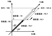
- FIGS. 6A and 6B are diagrams for explaining the position deviation of the tilt axis.
- the Yi axis in FIG. 6A is a virtual axis perpendicular to the Xm axis.
- the Xm axis and the Ym axis are respectively the X axis and the Y axis of the master axis belonging to the first system.
- the Ym axis is arranged at an angle of 30° with respect to the Yi axis. In other words, the angle between the Xm axis and the Ym axis is 60°.
- the Yi axis in FIG. 6B is a virtual axis perpendicular to the Xs axis.
- the Xs axis and the Ys axis are the X axis and the Y axis, respectively, of the slave axis belonging to the second system.
- the Ys axis is inclined at 45° with respect to the Yi axis. In other words, the angle between the Xs axis and the Ys axis is 45°.
- the command value for the Yi axis is converted to a command value for the Ym axis.
- the command value in the Cartesian coordinate system is converted to a command value in the tilted coordinate system. Note that the command values in the tilted coordinate system shown below are rounded to one decimal place.
- the command value of 100 for the first spindle head is converted to a command value of 115.5 on the Ym axis.
- the first spindle head moves, for example, to position 69.3 on the Ym axis.
- the movement amount of the first spindle head is 69.3.
- the position deviation of the Ym axis of the first spindle head in this case is 46.2.
- the second spindle head moves in synchronization with the first spindle head.
- the command value for the Ym axis is converted to a command value for the Yi axis
- the command value for the Yi axis is further converted to a command value for the Ys axis.
- the command value in the tilted coordinate system of the first spindle head is converted to a command value in a Cartesian coordinate system
- the command value in the Cartesian coordinate system is further converted to a command value in the tilted coordinate system of the second spindle head.
- the command value of 100 for the Yi axis is converted to a command value of 141.4 on the Ys axis.
- the second spindle head moves, for example, to position 70.7 on the Ys axis.
- the amount of movement of the second spindle head is 70.7.
- the position deviation of the second spindle head on the Ys axis in this case is 70.7.
- the conversion unit 112 performs at least one of converting the first value acquired by the acquisition unit 111 into a third value indicating the position deviation of the master axis in a predetermined coordinate system, and converting the second value acquired by the acquisition unit 111 into a fourth value indicating the position deviation of the slave axis in a predetermined coordinate system.
- the conversion unit 112 converts the position deviation of the master axis and the position deviation of the slave axis into a position deviation in a common coordinate system for the master axis and the slave axis.
- the predetermined coordinate system is an inclined coordinate system or a Cartesian coordinate system.
- the conversion unit 112 converts the position deviation of the master axis into the position deviation of the orthogonal axis. That is, the position deviation of the master axis in the converted orthogonal coordinate system is the third value.
- the conversion unit 112 converts the position deviation of 46.2 of the Ym axis into the position deviation of 40 of the Yi axis.
- the conversion unit 112 converts the position deviation of the slave axis into the position deviation of the orthogonal axis. That is, the position deviation of the slave axis in the converted orthogonal coordinate system is the fourth value. In the example shown in FIG. 6B, the conversion unit 112 converts the position deviation of 70.7 on the Ys axis into the position deviation of 50 on the Yi axis.
- the conversion unit 112 does not convert the position deviation of the master axis. Also, if the master axis is included in a tilted coordinate system and the slave axis is included in a Cartesian coordinate system, the conversion unit 112 does not convert the position deviation of the slave axis.
- the conversion unit 112 may convert either the position deviation of the master axis or the position deviation of the slave axis into a position deviation in the other coordinate system. For example, when the master axis is included in a Cartesian coordinate system and the slave axis is included in a tilted coordinate system, the conversion unit 112 may convert the position deviation of the master axis into a position deviation in the tilted coordinate system. Alternatively, when the master axis is included in a tilted coordinate system and the slave axis is included in a Cartesian coordinate system, the conversion unit 112 may convert the position deviation of the slave axis into a position deviation in the tilted coordinate system.
- the master axis may be included in a first inclined coordinate system
- the slave axis may be included in a second inclined coordinate system different from the first inclined coordinate system.
- the conversion unit 112 may convert the position deviation of the master axis in the first inclined coordinate system into the position deviation of the slave axis in the second inclined coordinate system.
- the conversion unit 112 may convert the position deviation of the slave axis in the second inclined coordinate system into the position deviation of the master axis in the first inclined coordinate system.
- the conversion unit 112 may convert the position deviation of the master axis and the position deviation of the slave axis into the position deviation of a third coordinate system different from the first coordinate system and the second coordinate system.
- the calculation unit 113 calculates the amount of deviation between the position deviation of the master axis and the position deviation of the slave axis in a specified coordinate system based on the first value and the fourth value, the second value and the third value, or the third value and the fourth value.
- the calculation unit 113 calculates the amount of deviation based on the first value and the fourth value.
- the calculation unit 113 calculates the amount of deviation by finding the difference between the first value and the fourth value, or the absolute value of the difference between the first value and the fourth value.
- the calculation unit 113 calculates the amount of deviation based on the second value and the third value.
- the calculation unit 113 calculates the amount of deviation by finding the difference between the second value and the third value, or the absolute value of the difference between the second value and the third value.
- the calculation unit 113 calculates the amount of deviation based on the second value and the fourth value.
- the calculation unit 113 calculates the amount of deviation by finding the difference between the second value and the fourth value, or the absolute value of the difference between the second value and the fourth value.
- the calculation unit 113 calculates the deviation amount based on the second value and the fourth value.
- the value of the deviation amount calculated by the calculation unit 113 is 10.
- the output unit 114 outputs the deviation amount calculated by the calculation unit 113.
- the output unit 114 outputs the deviation amount to, for example, a monitor of the input/output device 107.
- the determination unit 115 compares the deviation amount calculated by the calculation unit 113 with a predetermined threshold value to determine whether or not a synchronization error has occurred between the master axis and the slave axis. The determination unit 115 determines whether or not a synchronization error has occurred for each control period, for example.
- the threshold value may be set, for example, in a parameter.
- the parameter is stored, for example, in a specified area of the non-volatile memory 105.
- the determination unit 115 determines that a synchronization error has occurred. For example, if the deviation amount calculated by the calculation unit 113 is equal to or less than a predetermined threshold value, the determination unit 115 determines that a synchronization error has not occurred.
- the output unit 114 outputs information that a synchronization error has occurred.
- the output unit 114 for example, displays information that a synchronization error has occurred on the monitor of the input/output device 107.
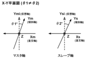
- FIGS. 7A and 7B are diagrams for explaining an example of the processing machine 2.
- the processing machine 2 has, for example, a first system and a second system.
- the first system includes a first spindle head H1.
- the second system includes a second spindle head H2.
- the first spindle head H1 and the second spindle head H2 are both positioned in the same direction when viewed from the workpiece W.
- the first spindle head H1 and the second spindle head H2 are positioned, for example, above the workpiece W.
- the coordinate system of the first system is an inclined coordinate system. Specifically, the Ym axis is inclined by ⁇ 1° with respect to the Ymi axis.
- the Ymi axis is a virtual axis perpendicular to the Xm axis. ⁇ 1° is an angle that indicates, for example, an installation error that occurs when installing a machine.
- the coordinate system of the second system is also an inclined coordinate system.
- the Ys axis is inclined by ⁇ 2° with respect to the Ysi axis, which is different from ⁇ 1°.
- the Ysi axis is a virtual axis perpendicular to the Xs axis.
- ⁇ 2° is an angle that indicates, for example, an installation error that occurs when installing a machine.
- the Xm-axis and Xs-axis are arranged parallel to each other.
- the Z-axis is a common axis to the tilted coordinate system of the first system and the tilted coordinate system of the second system.
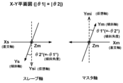
- FIGS. 8A and 8B are diagrams for explaining an example of a processing machine 2.
- the processing machine 2 has, for example, a first system and a second system.
- the first system includes a first spindle head H1.
- the second system includes a second spindle head H2.
- the first spindle head H1 and the second spindle head H2 are each positioned in different directions as viewed from the workpiece W.
- the first spindle head H1 is positioned, for example, above the workpiece W.
- the second spindle head H2 is positioned, for example, below the workpiece W.
- the coordinate system of the first system is an inclined coordinate system. Specifically, the Ym axis is inclined by ⁇ 1° with respect to the Ymi axis.
- the Ymi axis is a virtual axis perpendicular to the Xm axis. ⁇ 1° is an angle that indicates, for example, an installation error that occurs when installing a machine.
- the coordinate system of the second system is also an inclined coordinate system.
- the Ys axis is inclined by ⁇ 2° with respect to the Ysi axis, which is different from ⁇ 1°.
- the absolute value of ⁇ 1 is equal to the absolute value of ⁇ 2.
- ⁇ 1 - ⁇ 2 holds.
- the Ysi axis is a virtual axis that is perpendicular to the Xs axis.
- ⁇ 2° is an angle that indicates, for example, an installation error that occurs when installing a machine.
- the Xm-axis and Xs-axis are arranged parallel to each other. However, the positive and negative directions of the Xm-axis and Xs-axis are opposite to each other.
- the Zm-axis and Zs-axis are arranged parallel to each other.
- the Zm-axis and Zs-axis may be configured as a Z-axis common to the tilted coordinate system of the first system and the tilted coordinate system of the second system.
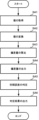
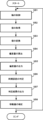
- FIG. 9 is a flowchart showing an example of a process executed in the calculation device 1.
- the acquisition unit 111 acquires the first value and the second value (step SA1).
- the conversion unit 112 converts the first value to a third value and/or converts the second value to a fourth value (step SA2).
- step SA3 calculates the deviation amount
- step SA4 outputs the deviation amount
- step SA5 judges whether or not a synchronization error has occurred.
- step SA6 the judgment result
- calculation device 1 executes control of the processing machine 2.
- FIG. 10 is a block diagram showing an example of the hardware configuration of the processing machine 2.
- the processing machine 2 includes a numerical control device 3, an input/output device 4, a servo amplifier 5, a servo motor 6, a spindle amplifier 7, a spindle motor 8, and an auxiliary device 9.
- the numerical control device 3 is a device for controlling the processing machine 2.
- the numerical control device 3 includes, for example, a hardware processor 301, a bus 302, a ROM (Read Only Memory) 303, a RAM (Random Access Memory) 304, and a non-volatile memory 305.
- the hardware processor 301 is a processor that controls the entire numerical control device 3 using a system program.
- the hardware processor 301 reads the system program and the like stored in the ROM 303 via the bus 302.
- the hardware processor 301 is, for example, a CPU or an electronic circuit.
- the bus 302 is a communication path that connects each piece of hardware in the numerical control device 3 to each other. Each piece of hardware in the numerical control device 3 exchanges data via the bus 302.
- ROM 303 is a storage device that stores system programs and the like. ROM 303 is a computer-readable storage medium.
- RAM 304 is a storage device that temporarily stores various data. RAM 304 functions as a working area for hardware processor 301 to process various data.
- the non-volatile memory 305 is a storage device that retains data even when the power to the numerical control device 3 is turned off.
- the non-volatile memory 305 stores, for example, a deviation calculation program.
- the non-volatile memory 305 is a computer-readable storage medium.
- the non-volatile memory 305 is, for example, a battery-backed memory or an SSD.
- the numerical control device 3 further includes an interface 306, an axis control circuit 307, a spindle control circuit 308, a PLC (Programmable Logic Controller) 309, and an I/O unit 310.
- an interface 306 an axis control circuit 307
- a spindle control circuit 308 a PLC (Programmable Logic Controller) 309
- an I/O unit 310 an I/O unit 310.
- the interface 306 connects the bus 302 and the input/output device 4. For example, the interface 306 sends various data processed by the hardware processor 301 to the input/output device 4.
- the input/output device 4 receives various data via the interface 306 and displays the various data on a display.
- the input/output device 4 also receives input of various data and sends the various data via the interface 306 to, for example, the hardware processor 301.
- the input/output device 4 is, for example, a touch panel.
- the input/output device 4 is, for example, a capacitive touch panel.
- the touch panel is not limited to a capacitive touch panel, and may be a touch panel of another type.
- the input/output device 4 is installed in an operation panel (not shown) in which the numerical control device 3 is stored.
- the axis control circuit 307 is a circuit for controlling the servo motor 6.
- the axis control circuit 307 receives control commands from the hardware processor 301 and sends various commands to the servo amplifier 5 for driving the servo motor 6.
- the axis control circuit 307 sends, for example, a torque command for controlling the torque of the servo motor 6 to the servo amplifier 5.
- the servo amplifier 5 receives commands from the axis control circuit 307 and supplies current to the servo motor 6.
- the servo motors 6 are driven by receiving a current supply from the servo amplifier 5.
- the servo motors 6 are provided corresponding to each control axis of the processing machine 2. If the processing machine 2 is a machine tool having five axes, the servo motors 6 include, for example, an X-axis servo motor, a Y-axis servo motor, a Z-axis servo motor, an A-axis servo motor, and a C-axis servo motor. In this case, an axis control circuit 307 and a servo amplifier 5 are provided for each servo motor 6.
- the servo motor 6 is connected to, for example, a ball screw that moves the structure of the processing machine 2.
- the structure of the processing machine 2 such as the spindle head, moves along a specified control axis.
- Servomotor 6 has a built-in encoder (not shown) that detects the position and feed speed of the control axis. Position feedback information and speed feedback information indicating the position of the control axis and the feed speed of the control axis detected by the encoder, respectively, are fed back to axis control circuit 307. In this way, axis control circuit 307 performs feedback control of each control axis.
- the spindle control circuit 308 is a circuit for controlling the spindle motor 8.
- the spindle control circuit 308 receives a control command from the hardware processor 301 and sends a command to the spindle amplifier 7 to drive the spindle motor 8.
- the spindle control circuit 308 sends, for example, a spindle speed command to the spindle amplifier 7 to control the rotation speed of the spindle motor 8.
- the spindle amplifier 7 receives commands from the spindle control circuit 308 and supplies current to the spindle motor 8.
- the spindle motor 8 is driven by a current supplied from the spindle amplifier 7.
- the spindle motor 8 is connected to the main shaft and rotates the main shaft.
- FIG. 10 only illustrates the servo motor 6 and spindle motor 8 that operate one system. However, if the processing machine 2 has multiple systems, the processing machine 2 is equipped with a servo motor 6 and a spindle motor 8 corresponding to each of the multiple systems.
- the PLC 309 is a device that executes a ladder program to control the auxiliary device 9.
- the PLC 309 sends commands to the auxiliary device 9 via the I/O unit 310.
- the I/O unit 310 is an interface that connects the PLC 309 and the auxiliary device 9.
- the I/O unit 310 sends commands received from the PLC 309 to the auxiliary device 9.
- the auxiliary device 9 is installed in the processing machine 2 and performs auxiliary operations in the processing machine 2.
- the auxiliary device 9 operates based on commands received from the I/O unit 310.
- the auxiliary device 9 may be a device installed in the periphery of the processing machine 2.
- the auxiliary device 9 is, for example, a tool changer, a cutting fluid injection device, or an opening/closing door drive device.
- FIG. 11 is a block diagram showing an example of the functions of the calculation device 1 implemented in the numerical control device 3.
- the calculation device 1 includes a control unit 116 in addition to the functions shown in FIG. 3.
- the control unit 116 controls each control axis of the processing machine 2 based on the processing program.
- the control unit 116 duplicates the movement amount of the master axis to control the slave axis.
- the control unit 116 duplicates the pulse signal for the master axis and controls the slave axis based on the duplicated pulse signal.
- control unit 116 copies the Ym-axis movement amount 115.5 to generate the Ys-axis movement amount 141.4.
- the control unit 116 controls the Ys-axis, which is the slave axis, based on the generated movement amount 141.4.
- the control unit 116 corrects the amount of movement of the slave axis using the deviation calculated by the calculation unit 113. That is, the control unit 116 performs control to match the amount of movement of the slave axis to the amount of movement of the master axis. For example, the control unit 116 increases the torque of the slave axis to match the amount of movement of the slave axis to the amount of movement of the master axis.
- the deviation amount in the Cartesian coordinate system is 10.
- the control unit 116 converts the deviation amount of 10 to a deviation amount of 14.1 on the Ys axis.
- the control unit 116 corrects the movement amount of the slave axis using the converted deviation amount of 14.1.
- the control unit 116 corrects the movement amount of the slave axis, for example, in the control cycle following the control cycle in which the deviation amount was calculated.
- FIG. 12 is a flowchart showing an example of processing executed by the calculation device 1 implemented in the numerical control device 3.
- control unit 116 controls the control axis based on the machining program (step SB1).
- acquisition unit 111 acquires the first value and the second value (step SB2).
- the conversion unit 112 converts the first value to a third value and/or converts the second value to a fourth value (step SB3).
- the calculation unit 113 calculates the deviation amount (step SB4).
- the output unit 114 outputs the deviation amount (step SB5).
- step SB6 judges whether or not a synchronization error has occurred.
- step SB7 judges whether or not a synchronization error has occurred.
- step SB8 outputs the judgment result (step SB7).
- step SB8 corrects the movement amount of the slave axis (step SB8). Note that the processing from step SB1 to step SB8 is repeatedly executed for each control cycle, and the processing ends when the execution of the machining program ends.
- the calculation device 1 includes an acquisition unit 111 that acquires a first value indicating the position deviation of the master axis and a second value indicating the position deviation of the slave axis that is arranged at an angle relative to the master axis, a conversion unit 112 that performs at least one of converting the first value acquired by the acquisition unit 111 into a third value indicating the position deviation of the master axis in a predetermined coordinate system and converting the second value acquired by the acquisition unit 111 into a fourth value indicating the position deviation of the slave axis in the predetermined coordinate system, a calculation unit 113 that calculates the amount of deviation between the position deviation of the master axis and the position deviation of the slave axis in the predetermined coordinate system based on the first value and the fourth value, the second value and the third value, or the third value and the fourth value, and an output unit 114 that outputs the amount of deviation calculated by the calculation unit 113.
- the computer-readable storage medium also stores instructions that cause the computer to perform at least one of the following: acquiring a first value indicating the position deviation of the master axis and a second value indicating the position deviation of a slave axis that is disposed at an inclination of a predetermined angle with respect to the master axis; converting the acquired first value into a third value indicating the position deviation of the master axis in a predetermined coordinate system; and converting the acquired second value into a fourth value indicating the position deviation of the slave axis in the predetermined coordinate system; calculating the amount of deviation between the position deviation of the master axis and the position deviation of the slave axis in the predetermined coordinate system based on the first value and the fourth value, the second value and the third value, or the third value and the fourth value; and outputting the calculated amount of deviation.
- the calculation device 1 or the computer can calculate the amount of deviation between the position deviation of the master axis and the position deviation of the slave axis that is arranged at an angle to the master axis. In other words, even if the inclination angles of the master axis and the slave axis are different, the amount of deviation between the master axis and the slave axis can be calculated.
- the specified coordinate system is an inclined coordinate system or an orthogonal coordinate system. Therefore, the calculation device 1 can calculate the deviation amount in various coordinate systems. Therefore, the calculation device 1 can easily perform error correction between the master axis and the slave axis.
- the calculation device 1 further includes a determination unit 115 that compares the deviation amount with a predetermined threshold value to determine whether or not a synchronization error occurs between the master axis and the slave axis. Therefore, the calculation device 1 does not need to perform error correction when the synchronization error is tolerable. As a result, the calculation device 1 can reduce the control load of the numerical control device 3.
- the calculation device 1 also includes a control unit 116 that replicates the amount of movement of the master axis to control the slave axis. Therefore, the calculation device 1 can synchronously control the master axis and the slave axis.
- the control unit 116 also corrects the amount of movement of the slave axis using the deviation calculated by the calculation unit 113.
- the calculation device 1 can correct the synchronization error between the master axis and the slave axis. Therefore, the calculation device 1 can control the processing machine 2 with high precision.
- Appendix [1] a conversion unit that converts the first value acquired by the acquisition unit into a third value that indicates a position deviation of the master axis in a predetermined coordinate system and/or converts the second value acquired by the acquisition unit into a fourth value that indicates a position deviation of the slave axis in the predetermined coordinate system; a calculation unit that calculates an amount of deviation between the position deviation of the master axis and the position deviation of the slave axis in the predetermined coordinate system based on the first value and the fourth value, the second value and the third value, or the third value and the fourth value; and an output unit that outputs the amount of deviation calculated by the calculation unit.
- Appendix [2] The calculation device according to claim 1, wherein the predetermined coordinate system is an inclined coordinate system or an orthogonal coordinate system.
- Appendix [3] The calculation device according to claim 1 or 2, further comprising a determination unit that compares the deviation amount with a predetermined threshold value to determine whether or not a synchronization error occurs between the master axis and the slave axis.
- Appendix [4] The calculation device according to any one of appendices [1] to [3], further comprising a control unit that replicates the amount of movement of the master axis to control the slave axis.
- Appendix [5] The calculation device according to claim [4], wherein the control unit corrects the movement amount of the slave axis by using the deviation amount calculated by the calculation unit.
- Appendix [6] a first value indicating a position deviation of a master axis and a second value indicating a position deviation of a slave axis arranged to be inclined at a predetermined angle with respect to the master axis; converting the acquired first value into a third value indicating a position deviation of the master axis in a predetermined coordinate system and/or converting the acquired second value into a fourth value indicating a position deviation of the slave axis in the predetermined coordinate system; calculating an amount of deviation between the position deviation of the master axis and the position deviation of the slave axis in the predetermined coordinate system based on the first value and the fourth value, the second value and the third value, or the third value and the fourth value; and outputting the calculated amount of deviation.
Landscapes
- Engineering & Computer Science (AREA)
- Human Computer Interaction (AREA)
- Manufacturing & Machinery (AREA)
- Physics & Mathematics (AREA)
- General Physics & Mathematics (AREA)
- Automation & Control Theory (AREA)
- Numerical Control (AREA)
Abstract
Description
付記[1]
マスタ軸の位置偏差を示す第1の値と、前記マスタ軸に対して所定の角度だけ傾斜して配置されるスレーブ軸の位置偏差を示す第2の値とを取得する取得部と、前記取得部によって取得された前記第1の値を所定の座標系における前記マスタ軸の位置偏差を示す第3の値に変換すること、および、前記取得部によって取得された前記第2の値を前記所定の座標系における前記スレーブ軸の位置偏差を示す第4の値に変換することの少なくともいずれかを実行する変換部と、前記第1の値および前記第4の値、前記第2の値および前記第3の値、または前記第3の値および前記第4の値に基づいて、前記所定の座標系における、前記マスタ軸の前記位置偏差と前記スレーブ軸の前記位置偏差との間の偏差量を算出する算出部と、前記算出部によって算出された前記偏差量を出力する出力部と、を備える算出装置。
付記[2]
前記所定の座標系は、傾斜座標系、または直交座標系である付記[1]に記載の算出装置。
付記[3]
前記偏差量とあらかじめ定められたしきい値とを比較して前記マスタ軸と前記スレーブ軸との間に同期誤差が発生しているか否かを判定する判定部をさらに備える付記[1]または[2]に記載の算出装置。
付記[4]
前記マスタ軸の移動量を複製して前記スレーブ軸を制御する制御部をさらに備える付記[1]~[3]のいずれかに記載の算出装置。
付記[5]
前記制御部は、前記算出部によって算出された前記偏差量を用いて前記スレーブ軸の前記移動量を補正する付記[4]に記載の算出装置。
付記[6]
マスタ軸の位置偏差を示す第1の値と、前記マスタ軸に対して所定の角度だけ傾斜して配置されるスレーブ軸の位置偏差を示す第2の値とを取得することと、取得された前記第1の値を所定の座標系における前記マスタ軸の位置偏差を示す第3の値に変換すること、および、取得された前記第2の値を前記所定の座標系における前記スレーブ軸の位置偏差を示す第4の値に変換することの少なくともいずれかを実行することと、前記第1の値および前記第4の値、前記第2の値および前記第3の値、または前記第3の値および前記第4の値に基づいて、前記所定の座標系における、前記マスタ軸の前記位置偏差と前記スレーブ軸の前記位置偏差との間の偏差量を算出することと、算出された前記偏差量を出力することと、をコンピュータに実行させる命令を記憶するコンピュータ読み取り可能な記憶媒体。
101 ハードウェアプロセッサ
102 バス
103 ROM
104 RAM
105 不揮発性メモリ
106 インタフェース
107 入出力装置
108 通信装置
111 取得部
112 変換部
113 算出部
114 出力部
115 判定部
116 制御部
2 加工機
3 数値制御装置
301 ハードウェアプロセッサ
302 バス
303 ROM
304 RAM
305 不揮発性メモリ
306 インタフェース
307 軸制御回路
308 スピンドル制御回路
309 PLC
310 I/Oユニット
4 入出力装置
5 サーボアンプ
6 サーボモータ
7 スピンドルアンプ
8 スピンドルモータ
9 補助機器
Claims (6)
- マスタ軸の位置偏差を示す第1の値と、前記マスタ軸に対して所定の角度だけ傾斜して配置されるスレーブ軸の位置偏差を示す第2の値とを取得する取得部と、
前記取得部によって取得された前記第1の値を所定の座標系における前記マスタ軸の位置偏差を示す第3の値に変換すること、および、前記取得部によって取得された前記第2の値を前記所定の座標系における前記スレーブ軸の位置偏差を示す第4の値に変換することの少なくともいずれかを実行する変換部と、
前記第1の値および前記第4の値、前記第2の値および前記第3の値、または前記第3の値および前記第4の値に基づいて、前記所定の座標系における、前記マスタ軸の前記位置偏差と前記スレーブ軸の前記位置偏差との間の偏差量を算出する算出部と、
前記算出部によって算出された前記偏差量を出力する出力部と、
を備える算出装置。 - 前記所定の座標系は、傾斜座標系、または直交座標系である請求項1に記載の算出装置。
- 前記偏差量とあらかじめ定められたしきい値とを比較して前記マスタ軸と前記スレーブ軸との間に同期誤差が発生しているか否かを判定する判定部をさらに備える請求項1または2に記載の算出装置。
- 前記マスタ軸の移動量を複製して前記スレーブ軸を制御する制御部をさらに備える請求項1~3のいずれか1項に記載の算出装置。
- 前記制御部は、前記算出部によって算出された前記偏差量を用いて前記スレーブ軸の前記移動量を補正する請求項4に記載の算出装置。
- マスタ軸の位置偏差を示す第1の値と、前記マスタ軸に対して所定の角度だけ傾斜して配置されるスレーブ軸の位置偏差を示す第2の値とを取得することと、
取得された前記第1の値を所定の座標系における前記マスタ軸の位置偏差を示す第3の値に変換すること、および、取得された前記第2の値を前記所定の座標系における前記スレーブ軸の位置偏差を示す第4の値に変換することの少なくともいずれかを実行することと、
前記第1の値および前記第4の値、前記第2の値および前記第3の値、または前記第3の値および前記第4の値に基づいて、前記所定の座標系における、前記マスタ軸の前記位置偏差と前記スレーブ軸の前記位置偏差との間の偏差量を算出することと、
算出された前記偏差量を出力することと、
をコンピュータに実行させる命令を記憶するコンピュータ読み取り可能な記憶媒体。
Priority Applications (4)
| Application Number | Priority Date | Filing Date | Title |
|---|---|---|---|
| PCT/JP2023/011727 WO2024201557A1 (ja) | 2023-03-24 | 2023-03-24 | 算出装置およびコンピュータ読み取り可能な記憶媒体 |
| DE112023005575.0T DE112023005575T5 (de) | 2023-03-24 | 2023-03-24 | Berechnungsvorrichtung und computerlesbares speichermedium |
| JP2025509058A JPWO2024201557A1 (ja) | 2023-03-24 | 2023-03-24 | |
| CN202380095930.7A CN120883158A (zh) | 2023-03-24 | 2023-03-24 | 计算装置以及计算机可读存储介质 |
Applications Claiming Priority (1)
| Application Number | Priority Date | Filing Date | Title |
|---|---|---|---|
| PCT/JP2023/011727 WO2024201557A1 (ja) | 2023-03-24 | 2023-03-24 | 算出装置およびコンピュータ読み取り可能な記憶媒体 |
Publications (1)
| Publication Number | Publication Date |
|---|---|
| WO2024201557A1 true WO2024201557A1 (ja) | 2024-10-03 |
Family
ID=92904053
Family Applications (1)
| Application Number | Title | Priority Date | Filing Date |
|---|---|---|---|
| PCT/JP2023/011727 Ceased WO2024201557A1 (ja) | 2023-03-24 | 2023-03-24 | 算出装置およびコンピュータ読み取り可能な記憶媒体 |
Country Status (4)
| Country | Link |
|---|---|
| JP (1) | JPWO2024201557A1 (ja) |
| CN (1) | CN120883158A (ja) |
| DE (1) | DE112023005575T5 (ja) |
| WO (1) | WO2024201557A1 (ja) |
Citations (3)
| Publication number | Priority date | Publication date | Assignee | Title |
|---|---|---|---|---|
| JP2003131712A (ja) * | 2001-10-22 | 2003-05-09 | Nissan Motor Co Ltd | 多軸同期制御装置 |
| JP2008225533A (ja) * | 2007-03-08 | 2008-09-25 | Fanuc Ltd | サーボ制御装置 |
| JP2015191306A (ja) * | 2014-03-27 | 2015-11-02 | オークマ株式会社 | 工作機械の制御方法及び制御装置 |
-
2023
- 2023-03-24 JP JP2025509058A patent/JPWO2024201557A1/ja active Pending
- 2023-03-24 CN CN202380095930.7A patent/CN120883158A/zh active Pending
- 2023-03-24 WO PCT/JP2023/011727 patent/WO2024201557A1/ja not_active Ceased
- 2023-03-24 DE DE112023005575.0T patent/DE112023005575T5/de active Pending
Patent Citations (3)
| Publication number | Priority date | Publication date | Assignee | Title |
|---|---|---|---|---|
| JP2003131712A (ja) * | 2001-10-22 | 2003-05-09 | Nissan Motor Co Ltd | 多軸同期制御装置 |
| JP2008225533A (ja) * | 2007-03-08 | 2008-09-25 | Fanuc Ltd | サーボ制御装置 |
| JP2015191306A (ja) * | 2014-03-27 | 2015-11-02 | オークマ株式会社 | 工作機械の制御方法及び制御装置 |
Also Published As
| Publication number | Publication date |
|---|---|
| DE112023005575T5 (de) | 2025-12-18 |
| JPWO2024201557A1 (ja) | 2024-10-03 |
| CN120883158A (zh) | 2025-10-31 |
Similar Documents
| Publication | Publication Date | Title |
|---|---|---|
| JP4291386B2 (ja) | ワーク設置誤差補正手段を有する数値制御装置 | |
| CN100442180C (zh) | 数值控制装置 | |
| Zhou et al. | Adaptive feedrate interpolation with multiconstraints for five-axis parametric toolpath | |
| US11300943B2 (en) | Simulation device, numerical control device, and simulation method | |
| JP2009009274A (ja) | 数値制御装置 | |
| CN106886197B (zh) | 控制机器实施加工的方法及其装置和应用 | |
| JP2009538744A (ja) | 旋削加工を制御する方法、および旋削加工に適したnc機械 | |
| CN104635624A (zh) | 用于控制四轴加工设备的数控系统控制方法及其控制系统 | |
| WO2024201557A1 (ja) | 算出装置およびコンピュータ読み取り可能な記憶媒体 | |
| CN106886195B (zh) | 机加工控制方法及其装置和应用 | |
| WO2017101700A1 (zh) | 与数控系统直接通讯的计算机辅助制造方法及装置和系统 | |
| CN202362643U (zh) | 一种组合机床控制系统 | |
| CN117506547A (zh) | 数控机床的轮廓误差的检测方法、系统及装置 | |
| JP2016038674A (ja) | 工作機械の補正値演算方法及び補正値演算プログラム | |
| JP4734439B2 (ja) | 4軸加工機用数値制御装置 | |
| JPH0772913A (ja) | 工作機械の誤差補正方式 | |
| US20250181050A1 (en) | Machining surface estimation device and computer-readable storage medium | |
| CN109884982B (zh) | 数值控制装置 | |
| WO2025062584A9 (ja) | 数値制御装置およびコンピュータ読み取り可能な記憶媒体 | |
| WO2022264338A1 (ja) | 制御装置、干渉チェック装置、及び制御システム | |
| JP2010271898A (ja) | 4軸加工機用数値制御装置 | |
| WO2025022535A1 (ja) | 出力装置およびコンピュータ読み取り可能な記憶媒体 | |
| US12449786B2 (en) | Program analyzer and control system | |
| US12481269B2 (en) | Numerical control device and computer-readable storage medium | |
| JP7804154B1 (ja) | 制御装置 |
Legal Events
| Date | Code | Title | Description |
|---|---|---|---|
| 121 | Ep: the epo has been informed by wipo that ep was designated in this application |
Ref document number: 23930199 Country of ref document: EP Kind code of ref document: A1 |
|
| WWE | Wipo information: entry into national phase |
Ref document number: 2025509058 Country of ref document: JP |
|
| WWE | Wipo information: entry into national phase |
Ref document number: 112023005575 Country of ref document: DE |
|
| WWE | Wipo information: entry into national phase |
Ref document number: 202380095930.7 Country of ref document: CN |
|
| WWP | Wipo information: published in national office |
Ref document number: 202380095930.7 Country of ref document: CN |
|
| WWP | Wipo information: published in national office |
Ref document number: 112023005575 Country of ref document: DE |
|
| 122 | Ep: pct application non-entry in european phase |
Ref document number: 23930199 Country of ref document: EP Kind code of ref document: A1 |