WO2024195151A1 - 車両制御装置 - Google Patents
車両制御装置 Download PDFInfo
- Publication number
- WO2024195151A1 WO2024195151A1 PCT/JP2023/028825 JP2023028825W WO2024195151A1 WO 2024195151 A1 WO2024195151 A1 WO 2024195151A1 JP 2023028825 W JP2023028825 W JP 2023028825W WO 2024195151 A1 WO2024195151 A1 WO 2024195151A1
- Authority
- WO
- WIPO (PCT)
- Prior art keywords
- application execution
- virtual
- vehicle control
- output
- input
- Prior art date
- Legal status (The legal status is an assumption and is not a legal conclusion. Google has not performed a legal analysis and makes no representation as to the accuracy of the status listed.)
- Ceased
Links
Images


Classifications
-
- G—PHYSICS
- G06—COMPUTING OR CALCULATING; COUNTING
- G06F—ELECTRIC DIGITAL DATA PROCESSING
- G06F9/00—Arrangements for program control, e.g. control units
- G06F9/06—Arrangements for program control, e.g. control units using stored programs, i.e. using an internal store of processing equipment to receive or retain programs
- G06F9/44—Arrangements for executing specific programs
- G06F9/455—Emulation; Interpretation; Software simulation, e.g. virtualisation or emulation of application or operating system execution engines
- G06F9/45533—Hypervisors; Virtual machine monitors
- G06F9/45558—Hypervisor-specific management and integration aspects
-
- B—PERFORMING OPERATIONS; TRANSPORTING
- B60—VEHICLES IN GENERAL
- B60R—VEHICLES, VEHICLE FITTINGS, OR VEHICLE PARTS, NOT OTHERWISE PROVIDED FOR
- B60R16/00—Electric or fluid circuits specially adapted for vehicles and not otherwise provided for; Arrangement of elements of electric or fluid circuits specially adapted for vehicles and not otherwise provided for
- B60R16/02—Electric or fluid circuits specially adapted for vehicles and not otherwise provided for; Arrangement of elements of electric or fluid circuits specially adapted for vehicles and not otherwise provided for electric constitutive elements
- B60R16/023—Electric or fluid circuits specially adapted for vehicles and not otherwise provided for; Arrangement of elements of electric or fluid circuits specially adapted for vehicles and not otherwise provided for electric constitutive elements for transmission of signals between vehicle parts or subsystems
-
- G—PHYSICS
- G06—COMPUTING OR CALCULATING; COUNTING
- G06F—ELECTRIC DIGITAL DATA PROCESSING
- G06F11/00—Error detection; Error correction; Monitoring
- G06F11/07—Responding to the occurrence of a fault, e.g. fault tolerance
- G06F11/14—Error detection or correction of the data by redundancy in operations
- G06F11/1402—Saving, restoring, recovering or retrying
- G06F11/1415—Saving, restoring, recovering or retrying at system level
- G06F11/1438—Restarting or rejuvenating
-
- G—PHYSICS
- G06—COMPUTING OR CALCULATING; COUNTING
- G06F—ELECTRIC DIGITAL DATA PROCESSING
- G06F11/00—Error detection; Error correction; Monitoring
- G06F11/07—Responding to the occurrence of a fault, e.g. fault tolerance
- G06F11/14—Error detection or correction of the data by redundancy in operations
- G06F11/1479—Generic software techniques for error detection or fault masking
- G06F11/1482—Generic software techniques for error detection or fault masking using middleware or operating system [OS] functionalities
- G06F11/1484—Generic software techniques for error detection or fault masking using middleware or operating system [OS] functionalities involving virtual machines
-
- G—PHYSICS
- G06—COMPUTING OR CALCULATING; COUNTING
- G06F—ELECTRIC DIGITAL DATA PROCESSING
- G06F11/00—Error detection; Error correction; Monitoring
- G06F11/07—Responding to the occurrence of a fault, e.g. fault tolerance
- G06F11/16—Error detection or correction of the data by redundancy in hardware
- G06F11/1629—Error detection by comparing the output of redundant processing systems
- G06F11/1641—Error detection by comparing the output of redundant processing systems where the comparison is not performed by the redundant processing components
-
- G—PHYSICS
- G06—COMPUTING OR CALCULATING; COUNTING
- G06F—ELECTRIC DIGITAL DATA PROCESSING
- G06F9/00—Arrangements for program control, e.g. control units
- G06F9/06—Arrangements for program control, e.g. control units using stored programs, i.e. using an internal store of processing equipment to receive or retain programs
- G06F9/44—Arrangements for executing specific programs
- G06F9/455—Emulation; Interpretation; Software simulation, e.g. virtualisation or emulation of application or operating system execution engines
- G06F9/45533—Hypervisors; Virtual machine monitors
- G06F9/45558—Hypervisor-specific management and integration aspects
- G06F2009/45579—I/O management, e.g. providing access to device drivers or storage
Definitions
- the present invention relates to a vehicle control device that controls the running state of a vehicle.
- Patent Document 1 discloses a technology that uses virtual machines to integrate multiple applications into a single electronic control device, and divides the actual storage that stores files for each virtual machine.
- Patent Document 1 According to the technology disclosed in Patent Document 1, each application is only permitted to access the storage allocated to it, making it possible to prevent each application from erroneously accessing storage allocated to other applications.
- Patent Document 1 does not anticipate a case in which multiple applications, each of which controls multiple devices such as sensors and actuators, are integrated into a single electronic control device.
- the present invention was made in consideration of the above problems, and its purpose is to provide a vehicle control device that can execute multiple applications that each control multiple devices while ensuring their independence from each other.
- the present invention provides a vehicle control device that controls multiple devices, the vehicle control device comprising multiple device I/O units that input and output signals to and from the multiple devices, and multiple application execution environments that correspond to the multiple devices and are isolated from one another, the multiple application execution environments having multiple virtual I/O units that correspond to the multiple device I/O units.
- FIG. 1 is a configuration diagram of a vehicle control device according to an embodiment of the present invention.
- FIG. 2 is a configuration diagram showing an interface of a virtual input/output unit according to an embodiment of the present invention.
- FIG. 1 is a configuration diagram when the present invention is applied to an ECU1 (Electronic Control Unit), which is an electronic control device for an automobile.
- ECU1 Electronic Control Unit
- a number of devices are connected to the ECU1, such as sensors for measuring the environment around the vehicle and actuators for controlling vehicle driving and equipment.
- the inverter 2 is a device that drives the power steering and the drive system for electric vehicles.
- the door motor 3 is a device that opens and closes the door.
- the camera 4 is a device that recognizes the environment, such as detecting obstacles in front.
- the PWM output wiring 21 is a wiring that connects the ECU1 and the inverter 2, and outputs a PWM waveform.
- the DI wiring 31 and the DO wiring 32 are wiring that connect the ECU1 and the door motor 3, and control the digital input and digital output.
- the CAN communication wiring 41 is a wiring that connects the ECU1 and the camera 4, and controls the CAN (Control Area Network) communication.
- the virtual machine A11 is an application execution environment provided for the inverter 2.
- the virtual machine B12 is an application execution environment provided for the door motor 3.
- the virtual machine C13 is an application execution environment provided for the camera 4.
- the virtual machines 11, 12, and 13 are managed in an isolated state by the hypervisor 15, and each virtual machine cannot directly access the other virtual machines. However, the virtual machines can exchange information with each other via a virtual communication channel (not shown) provided between the virtual machines.
- the virtual input/output management unit 14 manages the operation status of the ECU virtual input/output units (ECU virtual input/output unit A112, ECU virtual input/output unit B122, ECU virtual input/output unit C132) provided in the virtual machines (virtual machine A11, virtual machine B12, and virtual machine C13), and performs recovery processing such as restarting in the event of a malfunction.
- the hypervisor 15 controls the execution of the virtual machines (virtual machine A11, virtual machine B12, and virtual machine C13) in the ECU 1.
- the ECU input/output unit 16 controls the input/output (analog input/output, digital input/output, communication, etc.) in the ECU.
- the ECU input/output unit 16 includes multiple device input/output units 16a, 16b, and 16c corresponding to each of the devices 2, 3, and 4.
- the app A111 is a software application for controlling the inverter 2.
- the ECU virtual input/output unit A112 is a virtual input/output unit corresponding to the device input/output unit 16a for controlling the inverter 2.
- the app B121 is a software application for controlling the door motor 3.
- the ECU virtual input/output unit B122 is a virtual input/output unit corresponding to the device input/output unit 16b for controlling the door motor 3.
- the app A131 is a software application for controlling the camera 4.
- the ECU virtual input/output unit C132 is a virtual input/output unit corresponding to the device input/output unit 16c for controlling the camera 4.
- an isolated application execution environment is provided for each device for controlling the vehicle, and a virtual input/output unit is provided for each isolated application execution environment.
- the reliability level (ASIL) of electronic control systems is determined according to the importance of the control function.
- ASIL levels When multiple devices are controlled by a single electronic control device, control of devices with different ASIL levels will be mixed.
- FIG. 2 is a configuration diagram showing the interfaces of the virtual input/output units 112, 122, and 132 in this embodiment.
- the virtual input/output interface 113 is provided in correspondence with the PWM output wiring 21 that connects the ECU 1 and the inverter 2.
- the virtual input/output interface 123 is provided in correspondence with the DI wiring 31 that connects the ECU 1 and the door motor 3.
- the virtual input/output interface 124 is provided in correspondence with the DO wiring 32 that connects the ECU 1 and the door motor 3.
- the virtual input/output interface 133 is provided in correspondence with the CAN communication wiring 41 that connects the ECU 1 and the camera 4.
- a virtual input/output unit 112, 122, 132 is provided for each of the isolated application execution environments 11, 12, 13, and the virtual input/output units 112, 122, 132 are provided with virtual input/output interfaces 113, 123, 124, 133 corresponding to the wiring 21, 31, 32, 41 connecting the ECU 1 and the devices 2, 3, 4.
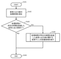
- FIG. 3 is a flowchart showing the process flow of the virtual I/O unit A112 in this embodiment. Processing begins in step S1121. In step S1122, a request to use the virtual I/O interface 113 from the application A111 is accepted. In step S1123, the device I/O unit 16a corresponding to the virtual I/O interface 113 is identified. In step S1124, the device I/O unit 16a executes a process for controlling PWM I/O, for example, writing to a register. Processing ends in step S1125.
- the virtual input/output units 112, 122, 132 convert input/output requests to the virtual input/output interfaces 113, 123, 124, 133 into input/output of the vehicle control device 1.
- the ECU that executes the virtual machines 11, 12, 13 is changed, for example, when the applications 111, 121, 131 are developed in individual ECUs for each device at the development stage, and when the applications 111, 121, 131 are integrated into one ECU at the productization stage, only the ECU virtual input/output units 112, 122, 132 need to be changed, improving the reusability of the applications 111, 121, 131.
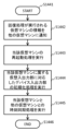
- FIG. 4 is a flowchart showing the process flow of the virtual I/O management unit 14 in this embodiment. Processing starts in step S141. In step S142, the processing times of the virtual I/O units 112, 122, and 132 are measured. In step S143, it is determined whether or not there is a virtual I/O unit whose processing time has exceeded a predetermined time. If there is a virtual I/O unit whose processing time has exceeded the predetermined time, the process proceeds to step S144, and if there is no virtual I/O unit whose processing time has exceeded the predetermined time, the process proceeds to step S145. In step S144, recovery processing is executed for the virtual machine (application execution environment) to which the virtual I/O unit whose processing time has exceeded the predetermined time belongs. The process ends in step S145.
- step S142 the processing times of the virtual I/O units 112, 122, and 132 are measured.
- step S143 it is determined whether or not there is a virtual I/O unit whose processing time has exceeded a predetermined time.
- the virtual I/O management unit 14 monitors whether each of the virtual I/O units 112, 122, 132 completes processing within a predetermined time (steps S142, S143), and if any of the virtual I/O units does not complete processing within the predetermined time, executes recovery processing of the virtual machine (application execution environment) to which the virtual I/O unit belongs (step S144).
- recovery processing of that one of the virtual machines can be executed without restarting the entire ECU, making it possible to continue processing of applications that require high reliability.
- FIG. 5 is a flowchart showing the flow of recovery processing of a virtual I/O unit by the virtual I/O management unit 14 in this embodiment.
- Processing starts in step S1441.
- step S1442 information about the virtual machine on which recovery processing is being performed is notified to other virtual machines that are not performing recovery processing.
- step S1443 restart processing of the virtual machine is performed.
- step S1444 initialization processing of the device I/O unit corresponding to the virtual I/O unit belonging to the virtual machine is performed.
- step S1445 time synchronization processing between the virtual machine and the other virtual machines is performed. Processing ends in step S1446.
- a vehicle control device 1 that controls multiple devices 2, 3, and 4 is equipped with device input/output units 16a, 16b, and 16c that input and output signals between the multiple devices 2, 3, and 4, and multiple application execution environments 11, 12, and 13 that are isolated from each other and correspond to each of the multiple devices 2, 3, and 4, and the multiple application execution environments 11, 12, and 13 have multiple virtual input/output units 112, 122, and 132 that correspond to the multiple device input/output units 16a, 16b, and 16c.
- the multiple application execution environments 11, 12, 13 in this embodiment have multiple virtual input/output interfaces 113, 123, 124, 133 corresponding to the wiring 21, 31, 32, 41 connecting the multiple devices 2, 3, 4 and the vehicle control device 1.
- the ECU that runs the virtual machines 11, 12, 13 is changed, only the ECU virtual input/output units 112, 122, 132 need to be changed, improving the reusability of the applications 111, 121, 131.
- the present embodiment includes a virtual I/O management unit 14 that converts I/O requests to the multiple virtual I/O interfaces 113, 123, 124, and 133 into I/O requests to the multiple device I/O units 16a, 16b, and 16c. This makes it possible to prevent the applications 111, 121, and 131 running on the application execution environments 11, 12, and 13 from directly accessing the I/O unit 16 of the vehicle control device 1.
- the virtual input/output management unit 14 in this embodiment monitors the operating status of the multiple virtual input/output units 112, 122, and 132. This makes it possible to determine whether the application execution environments 11, 12, and 13 are operating normally.
- the virtual I/O management unit 14 in this embodiment monitors whether the multiple virtual I/O units 112, 122, and 132 complete processing within a predetermined time, and if a specific virtual I/O unit among the multiple virtual I/O units 112, 122, and 132 does not complete processing within the predetermined time, executes recovery processing for a specific application execution environment among the multiple application execution environments 11, 12, and 13 to which the specific virtual I/O unit belongs. This makes it possible to restore the operation of the application execution environment in which the error occurred if an error occurs in any of the application execution environments 11, 12, and 13.
- the recovery process of the specific application execution environment in this embodiment includes a process of notifying other application execution environments among the multiple application execution environments 11, 12, and 13 other than the specific application execution environment that recovery process of the specific application execution environment will be executed, a process of restarting the specific application execution environment, a process of initializing a specific device I/O unit among the multiple device I/O units 16a, 16b, and 16c that corresponds to a virtual I/O unit belonging to the specific application execution environment, and a process of synchronizing the time of the restarted specific application execution environment with the time of the other application execution environments. This makes it possible to maintain the functions of the other application execution environments even while the recovery process of the specific application execution environment is being executed.
- the multiple application execution environments 11, 12, and 13 in this embodiment are multiple virtual machines 11, 12, and 13 managed by a hypervisor 15. This makes it possible to easily realize multiple application execution environments 11, 12, and 13.
- the present invention is not limited to the above-described embodiment, and various modified examples are included.
- the above-described embodiment has been described in detail to clearly explain the present invention, and is not necessarily limited to having all of the described configurations.
- the above-described configurations, functions, processing units, processing means, etc. may be realized in hardware, in part or in whole, by designing, for example, an integrated circuit.
- the above-described configurations, functions, etc. may be realized in software by a processor interpreting and executing a program that realizes each function.
- Information such as programs, tables, files, etc. that realize each function can be stored in the processor's built-in memory, an external flash memory, an SSD (Solid State Drive), or other such storage device.
- 1...ECU vehicle control device
- 2...inverter device
- 3...door motor device
- 4...camera device
- 11, 12, 13...virtual machine application execution environment
- 14...virtual input/output management unit 15...hypervisor, 16...ECU input/output unit, 16a, 16b, 16c...device input/output unit, 21...PWM output wiring, 31...DI wiring, 32...DO wiring, 41...CAN communication wiring, 111...application, 112...ECU virtual input/output unit, 113...virtual input/output interface, 121...application, 122...ECU virtual input/output unit, 123, 124...virtual input/output interface, 131...application, 132...ECU virtual input/output unit, 133...virtual input/output interface.
Landscapes
- Engineering & Computer Science (AREA)
- Theoretical Computer Science (AREA)
- Physics & Mathematics (AREA)
- General Engineering & Computer Science (AREA)
- General Physics & Mathematics (AREA)
- Quality & Reliability (AREA)
- Software Systems (AREA)
- Mechanical Engineering (AREA)
- Safety Devices In Control Systems (AREA)
Abstract
本発明は、複数のデバイスをそれぞれ制御する複数のアプリケーションを互いの独立性を担保しつつ実行可能な車両制御装置を提供することを目的とする。そのために、複数のデバイス2,3,4を制御する車両制御装置1において、複数のデバイス2,3,4との間で信号の入出力を行うデバイス入出力部16a,16b,16cと、複数のデバイス2,3,4に対応した、互いに隔離された複数のアプリケーション実行環境11,12,13とを備え、複数のアプリケーション実行環境11,12,13は、複数のデバイス入出力部16a,16b,16cに対応した複数の仮想入出力部112,122,132を有する。
Description
本発明は、車両の走行状態を制御する車両制御装置に関する。
自動車分野においては、マイコン及びソフトウェアにより、車両の走行状態を管理するためのセンサ、アクチュエータなどの制御を行う電子制御装置が広く用いられている。近年の自動運転化、電動化などの技術の発展に伴い電子制御装置に求められる機能が増大しており、自動車に搭載される電子制御装置の数が増大するとともに、電子制御装置間での車載ネットワーク通信量が増大しつつある。そこで、複数のアプリケーションを一つの電子制御装置に統合することで、電子制御装置の数を抑制することが提案されている。
例えば特許文献1には、仮想マシンを用いて複数のアプリケーションを一つの電子制御装置に統合するとともに、ファイルを保存する実ストレージを仮想マシンごとに分割する技術が開示されている。
特許文献1に開示された技術によれば、各アプリケーションは自身に割り当てられたストレージへのアクセスのみが許可されるため、各アプリケーションが他のアプリケーションに割り当てられたストレージに誤ってアクセスすることを防止することが可能となる。しかしながら、特許文献1では、センサやアクチュエータなどの複数のデバイスをそれぞれ制御する複数のアプリケーションを一つの電子制御装置に統合する場合は想定されていない。
本発明は、上記課題に鑑みてなされたものであり、その目的は、複数のデバイスをそれぞれ制御する複数のアプリケーションを互いの独立性を担保しつつ実行可能な車両制御装置を提供することにある。
上記目的を達成するために、本発明は、複数のデバイスを制御する車両制御装置において、前記複数のデバイスとの間で信号の入出力を行う複数のデバイス入出力部と、前記複数のデバイスに対応した、互いに隔離された複数のアプリケーション実行環境とを備え、前記複数のアプリケーション実行環境は、前記複数のデバイス入出力部に対応した複数の仮想入出力部を有するものとする。
本発明によれば、車両制御装置において、各アプリケーションがデバイスを制御する際にアクセスするデバイス入出力部を他のアプリケーションが誤ってアクセスすることを防止することにより、複数のアプリケーションを互いの独立性を担保しつつ実行することが可能となる。
以下、本発明の実施形態について図面を用いて説明する。なお、各図中、同等の要素には同一の符号を付し、重複した説明は適宜省略する。
図1は、本発明を自動車の電子制御装置であるECU1(ECU:Electronic Control Unit)に適用した場合の構成図である。ECU1には、車両周辺の環境を計測するためのセンサおよび車両走行及び装備を制御するためのアクチュエータなどの複数のデバイスが接続されている。インバータ2は、パワーステアリング、電動車両用ドライブシステムなどの駆動を行うデバイスである。ドアモータ3は、ドアの開閉動作を行うデバイスである。カメラ4は、前方の障害物認識などの環境認識を行うデバイスである。PWM出力配線21は、ECU1とインバータ2とを接続する配線であり、PWM波形を出力している。DI配線31およびDO配線32はECU1とドアモータ3とを接続する配線であり、デジタル入力およびデジタル出力を制御している。CAN通信配線41はECU1とカメラ4とを接続する配線であり、CAN(Control Area Network)通信を制御している。
仮想マシンA11は、インバータ2に対応して設けられたアプリケーション実行環境である。仮想マシンB12は、ドアモータ3に対応して設けられたアプリケーション実行環境である。仮想マシンC13は、カメラ4に対応して設けられたアプリケーション実行環境である。仮想マシン11,12,13はハイパーバイザー15により互いに隔離された状態に管理されており、各仮想マシンは他の仮想マシンに直接アクセスすることはできない。ただし、仮想マシン間に設けられた仮想通信チャンネル(図示せず)を介して互いの情報を交換することは可能である。仮想入出力管理部14は、仮想マシン(仮想マシンA11、仮想マシンB12および仮想マシンC13)内に設けられたECU仮想入出力部(ECU仮想入出力部A112、ECU仮想入出力部B122、ECU仮想入出力部C132)の動作状況を管理し、不具合がある場合には再起動などの回復処理を実行する。ハイパーバイザー15は、ECU1における仮想マシン(仮想マシンA11、仮想マシンB12および仮想マシンC13)の実行を制御する。ECU入出力部16は、ECUにおける入出力(アナログ入出力、デジタル入出力、通信など)を制御する。ECU入出力部16は、各デバイス2,3,4に対応した複数のデバイス入出力部16a,16b,16cを含む。
アプリA111は、インバータ2を制御するためのソフトウェアアプリケーションである。ECU仮想入出力部A112は、インバータ2を制御するためのデバイス入出力部16aに対応した仮想的な入出力部である。
アプリB121は、ドアモータ3を制御するためのソフトウェアアプリケーションである。ECU仮想入出力部B122は、ドアモータ3を制御するためのデバイス入出力部16bに対応した仮想的な入出力部である。
アプリA131は、カメラ4を制御するためのソフトウェアアプリケーションである。ECU仮想入出力部C132は、カメラ4を制御するためのデバイス入出力部16cに対応した仮想的な入出力部である。
このように、車両を制御するためのデバイスごとに対応させて隔離されたアプリケーション実行環境を設けるとともに、隔離されたアプリケーション実行環境ごとに仮想入出力部を設ける。自動車制御においては、たとえば機能安全規格(ISO26262)で定義されているように、制御の機能の重要性に応じて電子制御システムの信頼性レベル(ASIL)が定められている。複数のデバイスを一つの電子制御装置で制御する場合には、ASILレベルが異なるデバイスの制御が混在することになる。本実施形態の構成を取ることにより、ASILレベルが低い(要求信頼性が低い)アプリケーション(例えばアプリB)が一時的なエラーを出した場合でも、ASILレベルが高い(要求信頼性が高い)アプリケーション(例えばアプリA)の入出力処理に影響を及ぼさないよう隔離することが可能となる。
図2は、本実施形態における仮想入出力部112,122,132のインタフェースを示す構成図である。仮想入出力インタフェース113は、ECU1とインバータ2とを接続しているPWM出力配線21に対応して設けられる。仮想入出力インタフェース123は、ECU1とドアモータ3とを接続しているDI配線31に対応して設けられる。仮想入出力インタフェース124は、ECU1とドアモータ3とを接続しているDO配線32に対応して設けられる。仮想入出力インタフェース133は、ECU1とカメラ4とを接続しているCAN通信配線41に対応して設けられる。
このように、隔離されたアプリケーション実行環境11,12,13ごとに仮想入出力部112,122,132を設けるとともに、仮想入出力部112,122,132にはECU1とデバイス2,3,4とを接続している配線21,31,32,41に対応した仮想入出力インタフェース113,123,124,133を設ける。本実施形態の構成を取ることにより、ASILレベルが低い(要求信頼性が低い)アプリケーション(例えばアプリB)が一時的なエラーを出した場合でも、ASILレベルが高い(要求信頼性が高い)アプリケーション(例えばアプリA)が使用しているデバイス入出力部に影響が及ぶことを防ぐことが可能となる。
図3は、本実施形態における仮想入出力部A112の処理の流れを示すフローチャートである。ステップS1121で処理を開始する。ステップS1122で、アプリA111からの仮想入出力インタフェース113利用要求を受け付ける。ステップS1123で、仮想入出力インタフェース113に対応したデバイス入出力部16aを特定する。ステップS1124で、デバイス入出力部16aにてPWM入出力を制御するための処理、例えばレジスタへの書き込みを実行する。ステップS1125で処理を終了する。
このように仮想入出力部112,122,132は、仮想入出力インタフェース113,123,124,133に対する入出力要求を車両制御装置1の入出力へと変換する。本実施形態の構成を取ることにより、例えば開発段階においてデバイス別に個別のECUでアプリケーション111,121,131を開発する場合と、製品化段階でアプリケーション111,121,131を一つのECUに統合する場合とにおいて仮想マシン11,12,13を実行するECUが変更される状況であっても、ECU仮想入出力部112,122,132のみを変更すればよくなるため、アプリケーション111,121,131の再利用性が向上する。
図4は、本実施形態における仮想入出力管理部14の処理の流れを示すフローチャートである。ステップS141で処理を開始する。ステップS142で、仮想入出力部112,122,132の処理時間を測定する。ステップS143で、処理時間が所定の時間を超過した仮想入出力部が有るか否かを判定する。処理時間が所定の時間を超過した仮想入出力部が有る場合にはステップS144に進み、処理時間が所定の時間を超過した仮想入出力部が無い場合にはステップS145に進む。ステップS144で、処理時間が所定の時間を超過した仮想入出力部が属する仮想マシン(アプリケーション実行環境)の回復処理を実行する。ステップS145で処理を終了する。
このように、仮想入出力管理部14は、各仮想入出力部112,122,132が所定の時間内に処理が完了するか否かを監視し(ステップS142,S143)、いずれかの仮想入出力部が所定の時間内に処理を完了しなかった場合には、当該仮想入出力部が属する仮想マシン(アプリケーション実行環境)の回復処理を実行する(ステップS144)。本実施形態の構成を取ることにより、一部の仮想入出力部でエラーが発生した場合に、ECU全体を再起動することなく当該一部の仮想マシンの回復処理を実行することができるため、高信頼性が要求されるアプリケーションの処理を継続することが可能となる。
図5は、本実施形態における仮想入出力管理部14による仮想入出力部の回復処理の流れを示すフローチャートである。ステップS1441で処理を開始する。ステップS1442で、回復処理が実行される仮想マシンの情報を、回復処理を実行しない他の仮想マシンに通知する。ステップS1443で、当該仮想マシンの再起動処理を実行する。ステップS1444で、当該仮想マシンに属する仮想入出力部に対応したデバイス入出力部の初期化処理を実行する。ステップS1445で、当該仮想マシンと他の仮想マシンとの時刻同期処理を実行する。ステップS1446で処理を終了する。
本実施形態の構成を取ることにより、一部の仮想マシンの再起動に伴って、ECU入出力部16の内、再起動される仮想マシンに属する仮想入出力部に対応したデバイス入出力部のみが初期化されるため、他の仮想マシンに属する仮想入出力部は処理を継続することができる。
(まとめ)
本実施形態では、複数のデバイス2,3,4を制御する車両制御装置1において、複数のデバイス2,3,4との間で信号の入出力を行うデバイス入出力部16a,16b,16cと、複数のデバイス2,3,4のそれぞれに対応した、互いに隔離された複数のアプリケーション実行環境11,12,13とを備え、複数のアプリケーション実行環境11,12,13は、複数のデバイス入出力部16a,16b,16cに対応した複数の仮想入出力部112,122,132を有する。
本実施形態では、複数のデバイス2,3,4を制御する車両制御装置1において、複数のデバイス2,3,4との間で信号の入出力を行うデバイス入出力部16a,16b,16cと、複数のデバイス2,3,4のそれぞれに対応した、互いに隔離された複数のアプリケーション実行環境11,12,13とを備え、複数のアプリケーション実行環境11,12,13は、複数のデバイス入出力部16a,16b,16cに対応した複数の仮想入出力部112,122,132を有する。
以上のように構成した本実施形態によれば、車両制御装置1において、各アプリケーション111,121,131がデバイス2,3,4を制御する際にアクセスするデバイス入出力部16a,16b,16cを他のアプリケーションが誤ってアクセスすることを防止することができるため、複数のアプリケーション111,121,131を互いの独立性を担保しつつ実行することが可能となる。
また、本実施形態における複数のアプリケーション実行環境11,12,13は、複数のデバイス2,3,4と車両制御装置1とを接続している配線21,31,32,41に対応した複数の仮想入出力インタフェース113,123,124,133を有する。これにより、仮想マシン11,12,13を実行するECUが変更される状況であっても、ECU仮想入出力部112,122,132のみを変更すればよくなるため、アプリケーション111,121,131の再利用性が向上する。
また、本実施形態における複数の仮想入出力インタフェース113,123,124,133に対する入出力要求を複数のデバイス入出力部16a,16b,16cへの入出力へと変換する仮想入出力管理部14を備える。これにより、アプリケーション実行環境11,12,13上で動作しているアプリケーション111,121,131が車両制御装置1の入出力部16に直接アクセスすることを防止することが可能となる。
また、本実施形態における仮想入出力管理部14は、複数の仮想入出力部112,122,132の動作状況を監視する。これにより、アプリケーション実行環境11,12,13が正常に動作しているか否かを判定することが可能となる。
また、本実施形態における仮想入出力管理部14は、複数の仮想入出力部112,122,132が所定の時間内に処理を完了するか否かを監視し、複数の仮想入出力部112,122,132のうち特定の仮想入出力部が前記所定の時間内に処理が完了しなかった場合に、複数のアプリケーション実行環境11,12,13のうち前記特定の仮想入出力部が属する特定のアプリケーション実行環境の回復処理を実行する。これにより、アプリケーション実行環境11,12,13のいずれかでエラーが生じた場合に、エラーが生じたアプリケーション実行環境の動作を復旧させることが可能となる。
また、本実施形態における前記特定のアプリケーション実行環境の回復処理は、複数のアプリケーション実行環境11,12,13のうち前記特定のアプリケーション実行環境以外の他のアプリケーション実行環境に対して、前記特定のアプリケーション実行環境の回復処理を実行する旨を通知する処理と、前記特定のアプリケーション実行環境を再起動する処理と、複数のデバイス入出力部16a,16b,16cのうち、前記特定のアプリケーション実行環境に属する仮想入出力部に対応した特定のデバイス入出力部を初期化する処理と、再起動した前記特定のアプリケーション実行環境の時刻を前記他のアプリケーション実行環境の時刻と同期させる処理とを含む。これにより、特定のアプリケーション実行環境の回復処理を実行中も、他のアプリケーション実行環境の機能を維持することが可能となる。
また、本実施形態における複数のアプリケーション実行環境11,12,13は、ハイパーバイザー15により管理された複数の仮想マシン11,12,13である。これにより、複数のアプリケーション実行環境11,12,13を容易に実現することが可能となる。
なお、本発明は上記した実施形態に限定されるものではなく、様々な変形例が含まれる。例えば、上記した実施形態は本発明を分かりやすく説明するために詳細に説明したものであり、必ずしも説明した全ての構成を備えるものに限定されるものではない。また、上記の各構成、機能、処理部、処理手段等は、それらの一部又は全部を、例えば集積回路で設計する等によりハードウェアで実現してもよい。また、上記の各構成、機能等は、プロセッサがそれぞれの機能を実現するプログラムを解釈し、実行することによりソフトウェアで実現してもよい。各機能を実現するプログラム、テーブル、ファイル等の情報は、プロセッサの内蔵メモリや、外付けのフラッシュメモリ、SSD(Solid State Drive)等の記録装置に置くことができる。
1…ECU(車両制御装置)、2…インバータ(デバイス)、3…ドアモータ(デバイス)、4…カメラ(デバイス)、11,12,13…仮想マシン(アプリケーション実行環境)、14…仮想入出力管理部、15…ハイパーバイザー、16…ECU入出力部、16a,16b,16c…デバイス入出力部、21…PWM出力配線、31…DI配線、32…DO配線、41…CAN通信配線、111…アプリケーション、112…ECU仮想入出力部、113…仮想入出力インタフェース、121…アプリケーション、122…ECU仮想入出力部、123,124…仮想入出力インタフェース、131…アプリケーション、132…ECU仮想入出力部、133…仮想入出力インタフェース。
Claims (7)
- 複数のデバイスを制御する車両制御装置において、
前記複数のデバイスとの間で信号の入出力を行う複数のデバイス入出力部と、
前記複数のデバイスに対応した、互いに隔離された複数のアプリケーション実行環境とを備え、
前記複数のアプリケーション実行環境は、前記複数のデバイス入出力部に対応した複数の仮想入出力部を有する
ことを特徴とする車両制御装置。 - 請求項1に記載の車両制御装置において、
前記複数のアプリケーション実行環境は、前記複数のデバイスと前記車両制御装置とを接続している配線に対応した複数の仮想入出力インタフェースを有する
ことを特徴とする車両制御装置。 - 請求項2に記載の車両制御装置において、
前記複数の仮想入出力インタフェースに対する入出力要求を前記複数のデバイス入出力部への入出力へと変換する仮想入出力管理部を備える
ことを特徴とする車両制御装置。 - 請求項3に記載の車両制御装置において、
前記仮想入出力管理部は、前記複数の仮想入出力部の動作状況を監視する
ことを特徴とする車両制御装置。 - 請求項4に記載の車両制御装置において、
前記仮想入出力管理部は、前記複数の仮想入出力部が所定の時間内に処理を完了するか否かを監視し、前記複数の仮想入出力部のうち特定の仮想入出力部が前記所定の時間内に処理が完了しなかった場合に、前記複数のアプリケーション実行環境のうち前記特定の仮想入出力部が属する特定のアプリケーション実行環境の回復処理を実行する
ことを特徴とする車両制御装置。 - 請求項5に記載の車両制御装置において、
前記特定のアプリケーション実行環境の回復処理は、
前記複数のアプリケーション実行環境のうち前記特定のアプリケーション実行環境以外の他のアプリケーション実行環境に対して、前記特定のアプリケーション実行環境の回復処理を実行する旨を通知する処理と、
前記特定のアプリケーション実行環境を再起動する処理と、
前記複数のデバイス入出力部のうち、前記特定のアプリケーション実行環境に属する仮想入出力部に対応した特定のデバイス入出力部を初期化する処理と、
再起動した前記特定のアプリケーション実行環境の時刻を前記他のアプリケーション実行環境の時刻と同期させる処理とを含む
ことを特徴とする車両制御装置。 - 請求項1に記載の車両制御装置において、
前記複数のアプリケーション実行環境は、ハイパーバイザーにより管理された複数の仮想マシンである
ことを特徴とする車両制御装置。
Priority Applications (1)
| Application Number | Priority Date | Filing Date | Title |
|---|---|---|---|
| DE112023004947.5T DE112023004947T5 (de) | 2023-03-23 | 2023-08-07 | Fahrzeugsteuergerät |
Applications Claiming Priority (2)
| Application Number | Priority Date | Filing Date | Title |
|---|---|---|---|
| JP2023046609A JP2024135757A (ja) | 2023-03-23 | 2023-03-23 | 車両制御装置 |
| JP2023-046609 | 2023-03-23 |
Publications (1)
| Publication Number | Publication Date |
|---|---|
| WO2024195151A1 true WO2024195151A1 (ja) | 2024-09-26 |
Family
ID=92841638
Family Applications (1)
| Application Number | Title | Priority Date | Filing Date |
|---|---|---|---|
| PCT/JP2023/028825 Ceased WO2024195151A1 (ja) | 2023-03-23 | 2023-08-07 | 車両制御装置 |
Country Status (3)
| Country | Link |
|---|---|
| JP (1) | JP2024135757A (ja) |
| DE (1) | DE112023004947T5 (ja) |
| WO (1) | WO2024195151A1 (ja) |
Citations (9)
| Publication number | Priority date | Publication date | Assignee | Title |
|---|---|---|---|---|
| JP2006252554A (ja) * | 2005-03-08 | 2006-09-21 | Microsoft Corp | 仮想マシン環境内でのゲスト物理アドレスの仮想化の方法およびシステム |
| WO2013175570A1 (ja) * | 2012-05-22 | 2013-11-28 | 富士通株式会社 | 情報処理装置、制御方法、及び制御プログラム |
| JP2014119789A (ja) * | 2012-12-13 | 2014-06-30 | Ntt Data Corp | 機能利用制御装置、機能利用制御方法、機能利用制御プログラム |
| JP2015521779A (ja) * | 2012-06-25 | 2015-07-30 | アドバンスト・マイクロ・ディバイシズ・インコーポレイテッドAdvanced Micro Devices Incorporated | 入力/出力仮想化のためのシステムおよび方法 |
| US20160170781A1 (en) * | 2014-12-11 | 2016-06-16 | Amazon Technologies, Inc. | Systems and methods for loading a virtual machine monitor during a boot process |
| JP2018112837A (ja) * | 2017-01-10 | 2018-07-19 | 株式会社東芝 | 仮想マシン管理装置、仮想マシン管理方法およびコンピュータプログラム |
| CN110442426A (zh) * | 2019-07-25 | 2019-11-12 | 腾讯科技(深圳)有限公司 | 一种密码重置方法、装置及存储介质 |
| JP2019212046A (ja) * | 2018-06-05 | 2019-12-12 | 富士通株式会社 | 制御プログラム、制御方法及び情報処理装置 |
| CN113746749A (zh) * | 2020-05-29 | 2021-12-03 | 阿里巴巴集团控股有限公司 | 网络连接设备 |
-
2023
- 2023-03-23 JP JP2023046609A patent/JP2024135757A/ja active Pending
- 2023-08-07 DE DE112023004947.5T patent/DE112023004947T5/de active Pending
- 2023-08-07 WO PCT/JP2023/028825 patent/WO2024195151A1/ja not_active Ceased
Patent Citations (9)
| Publication number | Priority date | Publication date | Assignee | Title |
|---|---|---|---|---|
| JP2006252554A (ja) * | 2005-03-08 | 2006-09-21 | Microsoft Corp | 仮想マシン環境内でのゲスト物理アドレスの仮想化の方法およびシステム |
| WO2013175570A1 (ja) * | 2012-05-22 | 2013-11-28 | 富士通株式会社 | 情報処理装置、制御方法、及び制御プログラム |
| JP2015521779A (ja) * | 2012-06-25 | 2015-07-30 | アドバンスト・マイクロ・ディバイシズ・インコーポレイテッドAdvanced Micro Devices Incorporated | 入力/出力仮想化のためのシステムおよび方法 |
| JP2014119789A (ja) * | 2012-12-13 | 2014-06-30 | Ntt Data Corp | 機能利用制御装置、機能利用制御方法、機能利用制御プログラム |
| US20160170781A1 (en) * | 2014-12-11 | 2016-06-16 | Amazon Technologies, Inc. | Systems and methods for loading a virtual machine monitor during a boot process |
| JP2018112837A (ja) * | 2017-01-10 | 2018-07-19 | 株式会社東芝 | 仮想マシン管理装置、仮想マシン管理方法およびコンピュータプログラム |
| JP2019212046A (ja) * | 2018-06-05 | 2019-12-12 | 富士通株式会社 | 制御プログラム、制御方法及び情報処理装置 |
| CN110442426A (zh) * | 2019-07-25 | 2019-11-12 | 腾讯科技(深圳)有限公司 | 一种密码重置方法、装置及存储介质 |
| CN113746749A (zh) * | 2020-05-29 | 2021-12-03 | 阿里巴巴集团控股有限公司 | 网络连接设备 |
Also Published As
| Publication number | Publication date |
|---|---|
| DE112023004947T5 (de) | 2025-10-23 |
| JP2024135757A (ja) | 2024-10-04 |
Similar Documents
| Publication | Publication Date | Title |
|---|---|---|
| US10127161B2 (en) | Method for the coexistence of software having different safety levels in a multicore processor system | |
| US9665469B2 (en) | System and method of runtime downloading of debug code and diagnostics tools in an already deployed baseboard management controller (BMC) devices | |
| CN107077407B (zh) | 车辆控制装置 | |
| KR20150067380A (ko) | 자동차를 제어하기 위한 리던던트 프로그램들 간에 데이터를 교환하기 위한 인터페이스 | |
| US6470430B1 (en) | Partitioning and monitoring of software-controlled system | |
| WO2015083251A1 (ja) | 監視装置、制御システム及び監視プログラム | |
| JP2015518605A (ja) | 安全アプリケーションのための機能アーキテクチャパターン | |
| CN107038095B (zh) | 用于冗余地处理数据的方法 | |
| JP2015067107A (ja) | 車両用制御装置 | |
| WO2022239331A1 (ja) | 電子制御装置及び異常判定方法 | |
| DE102019201607A1 (de) | Steuerungssystem für ein Kraftfahrzeug | |
| JP2024135757A (ja) | 車両制御装置 | |
| JP2010541056A (ja) | 給電電圧監視されるマイクロコントローラを有する車両制御ユニット、および関連の方法 | |
| CN110574343A (zh) | 用于保护车辆安全系统的操作系统的方法和半导体电路 | |
| Großmann et al. | Efficient application of multi-core processors as substitute of the E-Gas (Etc) monitoring concept | |
| JP6349444B2 (ja) | 車両用制御装置 | |
| KR20160097593A (ko) | 차량 제어 장치 및 차량 제어 방법 | |
| JP7504222B2 (ja) | 車載用制御システム | |
| CN110161835A (zh) | 用于计算安全关键的系统中的数据模型的方法和装置 | |
| JP7803720B2 (ja) | 制御装置及び電子制御装置 | |
| Schneider et al. | Basic single-microcontroller monitoring concept for safety critical systems | |
| US11422878B2 (en) | Control unit and method for operating a control unit | |
| CN121957777A (zh) | 虚拟机运行方法、装置及设备 | |
| JP7172155B2 (ja) | 電子制御装置及びソフトウエア生成方法 | |
| JP7000456B2 (ja) | 冗長処理システムにおけるエラー補正 |
Legal Events
| Date | Code | Title | Description |
|---|---|---|---|
| 121 | Ep: the epo has been informed by wipo that ep was designated in this application |
Ref document number: 23928727 Country of ref document: EP Kind code of ref document: A1 |
|
| WWE | Wipo information: entry into national phase |
Ref document number: 112023004947 Country of ref document: DE |
|
| WWP | Wipo information: published in national office |
Ref document number: 112023004947 Country of ref document: DE |
|
| 122 | Ep: pct application non-entry in european phase |
Ref document number: 23928727 Country of ref document: EP Kind code of ref document: A1 |