WO2024190852A1 - ヘッドアップディスプレイ装置 - Google Patents
ヘッドアップディスプレイ装置 Download PDFInfo
- Publication number
- WO2024190852A1 WO2024190852A1 PCT/JP2024/009915 JP2024009915W WO2024190852A1 WO 2024190852 A1 WO2024190852 A1 WO 2024190852A1 JP 2024009915 W JP2024009915 W JP 2024009915W WO 2024190852 A1 WO2024190852 A1 WO 2024190852A1
- Authority
- WO
- WIPO (PCT)
- Prior art keywords
- lens
- display
- light
- head
- display device
- Prior art date
- Legal status (The legal status is an assumption and is not a legal conclusion. Google has not performed a legal analysis and makes no representation as to the accuracy of the status listed.)
- Ceased
Links
Images



Classifications
-
- G—PHYSICS
- G02—OPTICS
- G02B—OPTICAL ELEMENTS, SYSTEMS OR APPARATUS
- G02B27/00—Optical systems or apparatus not provided for by any of the groups G02B1/00 - G02B26/00, G02B30/00
- G02B27/01—Head-up displays
- G02B27/0101—Head-up displays characterised by optical features
-
- G—PHYSICS
- G02—OPTICS
- G02B—OPTICAL ELEMENTS, SYSTEMS OR APPARATUS
- G02B19/00—Condensers, e.g. light collectors or similar non-imaging optics
- G02B19/0004—Condensers, e.g. light collectors or similar non-imaging optics characterised by the optical means employed
- G02B19/0009—Condensers, e.g. light collectors or similar non-imaging optics characterised by the optical means employed having refractive surfaces only
- G02B19/0014—Condensers, e.g. light collectors or similar non-imaging optics characterised by the optical means employed having refractive surfaces only at least one surface having optical power
-
- G—PHYSICS
- G02—OPTICS
- G02B—OPTICAL ELEMENTS, SYSTEMS OR APPARATUS
- G02B19/00—Condensers, e.g. light collectors or similar non-imaging optics
- G02B19/0033—Condensers, e.g. light collectors or similar non-imaging optics characterised by the use
- G02B19/0047—Condensers, e.g. light collectors or similar non-imaging optics characterised by the use for use with a light source
Definitions
- This disclosure relates to a head-up display device.
- the head-up display device described in Patent Document 1 displays a virtual image by emitting display light that represents an image toward the windshield of the vehicle.
- This head-up display device includes a backlight unit that emits illumination light, and a display unit that receives the illumination light from the backlight unit and emits the display light.
- This display unit includes a display panel that receives the illumination light and emits the display light, and a diffusion plate located on the back side of the display panel and diffusing the illumination light.
- the orientation of the display panel is tilted in a direction perpendicular to the direction of travel of the illumination light, which creates a difference in the optical path length of the display light in the vertical direction, making it possible to make the orientation of the virtual image closer to parallel to the road surface.
- the uniformity of the virtual image will decrease due to the difference in the optical path length of the display light.
- This disclosure has been made in consideration of the above-mentioned circumstances, and aims to provide a head-up display device that can improve the uniformity of a virtual image.
- the head-up display device includes a light source that emits illumination light, a lens through which the illumination light from the light source passes, a display that is oriented at a non-perpendicular angle to the direction in which the illumination light from the lens travels and receives the illumination light and emits display light, and a diffusion plate that is positioned non-parallel to the display and diffuses the illumination light from the lens and emits the diffused illumination light toward the display.
- FIG. 1 is a schematic diagram of a head-up display device according to a first embodiment of the present disclosure.
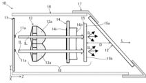
- 2 is a schematic cross-sectional view of a display unit according to the first embodiment of the present disclosure.
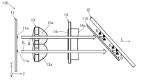
- FIG. FIG. 11 is a schematic cross-sectional view of a display unit according to a comparative example.
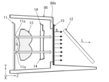
- FIG. 11 is a schematic cross-sectional view of a display unit according to a second embodiment of the present disclosure.
- 5A and 5B are schematic cross-sectional views of display units according to a comparative example and a modified example of the present disclosure.
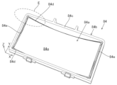
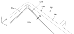
- FIG. 11 is a perspective view of a second lens according to a second embodiment of the present disclosure.
- FIG. 7 is an enlarged view of region E in FIG. 6.
- FIG. 11 is a perspective view of a display unit according to a second embodiment of the present disclosure.
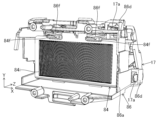
- FIG. 11 is a perspective view of a display unit in a state where a light source board and a first lens according to a second embodiment of the present disclosure are removed.
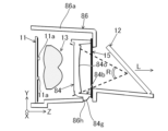
- 11 is a schematic cross-sectional view of a display unit according to a modified example of the present disclosure.
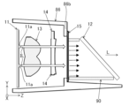
- 11 is a schematic cross-sectional view of a display unit according to a modified example of the present disclosure.
- the head-up display device 100 is installed in the dashboard of a vehicle 200.
- the head-up display device 100 emits display light L that displays an image toward a windshield 201, which is the front glass of the vehicle 200.
- the display light L is reflected by the windshield 201 and reaches a viewer 1 (mainly the driver of the vehicle 200).
- a virtual image V is displayed on a virtual image display surface K that is parallel to the road surface.
- the head-up display device 100 includes a display unit 10, a folding mirror 20, a concave mirror 30, and a housing 60.
- the housing 60 is made of non-translucent resin or metal and is a hollow, roughly rectangular parallelepiped. An opening is formed in the housing 60 at a position facing the windshield 201.
- the housing 60 has a window 62 that covers the opening.
- the window 62 is made of a translucent resin such as acrylic through which the display light L passes.
- the display unit 10, concave mirror 30, and folding mirror 20 are housed within the housing 60.
- the folding mirror 20 and the concave mirror 30 constitute an optical relay that guides the display light L from the display unit 10 to the windshield 201 .
- the folding mirror 20 reflects the display light L from the display unit 10 toward the concave mirror 30.
- the folding mirror 20 is a flat mirror. Note that the folding mirror 20 is not limited to a flat mirror, and may be a concave mirror.
- the concave mirror 30 reflects the display light L from the display unit 10 toward the windshield 201 while magnifying the light.
- the display unit 10 includes a light source substrate 11 having a plurality of light sources 11 a , a display panel 12 , an illumination optical system 18 , a lens holder 16 , and a display panel holder 17 .
- the illumination optical system 18 adjusts the illumination light IL from the light source 11a. Adjustment of the illumination light IL refers to collimating the illumination light IL, diffusing, scattering, or converging the illumination light IL.
- the illumination optical system 18 includes a first lens 13, a second lens 14, and a diffuser plate 15.
- the traveling direction of the illumination light IL emitted from the light source 11a is defined as the Z direction
- the vehicle height direction is defined as the Y direction
- the vehicle width direction is defined as the X direction.
- the X direction is the longitudinal direction of each of the lenses 13 and 14
- the Y direction is the lateral direction of each of the lenses 13 and 14.
- the first lens 13, the second lens 14, and the diffusion plate 15 are aligned in the Z direction so as to be parallel to each other.
- the lens holder 16 has a rectangular cylindrical shape that surrounds the periphery of the first lens 13, the second lens 14, and the diffusion plate 15, and holds the first lens 13, the second lens 14, and the diffusion plate 15 within the internal space of the lens holder 16.
- the light sources 11 a are mounted on a surface of the light source substrate 11 facing the first lens 13 .
- the first lens 13 is a condenser lens, and is formed into a plate shape from a light-transmitting resin or glass.
- the first lens 13 has a function of approximately collimating each light beam of the illumination light IL emitted from each light source 11a in the Z direction.
- the first lens 13 includes a plurality of convex lens portions 13a arranged in the X and Y directions. Each of the convex lens portions 13a is formed in a biconvex lens shape.
- the plurality of convex lens portions 13a are arranged in a matrix in one-to-one correspondence with the plurality of light sources 11a.
- the second lens 14 is a light distribution lens that expands the illumination light IL, which has been approximately collimated by the first lens 13, to fit the display area of the display panel 12, and is formed in a plate shape from translucent resin or glass.
- the second lens 14 has a light entrance surface 14i where light enters, and a light exit surface 14o from which light that has passed through the second lens 14 in its thickness direction exits.
- a cylindrical lens array that extends in the Y direction and is aligned in the X direction is formed on the light entrance surface 14i.
- a toroidal surface having different curvatures in the X and Y directions is formed on the light exit surface 14o.
- the diffuser plate 15 diffuses the illumination light IL from the second lens 14 and radiates it toward the display panel 12 in order to suppress unevenness in light intensity.
- the diffuser plate 15 faces the light exit surface 14o of the second lens 14.
- the display panel 12 is a TFT (Thin Film Transistor) type liquid crystal display panel. Under the control of a control unit (not shown), the display panel 12 receives illumination light IL that has passed through a diffusion plate 15 and emits display light L. The display panel 12 is oriented non-perpendicular to the traveling direction of the illumination light IL and non-parallel to the diffusion plate 15.
- the diffuser plate 15 includes a first portion 15a optically corresponding to the upper portion of the virtual image display surface K as viewed by the viewer, and a second portion 15b optically corresponding to the lower portion of the virtual image display surface K as viewed by the viewer.
- the orientation of the display panel 12 is set so that the distance D in the Z direction between the first portion 15a of the diffuser plate 15 and the display panel 12 is smaller than the distance D in the Z direction between the second portion 15b of the diffuser plate 15 and the display panel 12.
- the distance between the display panel 12 and the reflecting surface of the folding mirror 20 differs in the surface direction of the display panel 12, which causes a difference in the optical path length from the display panel 12 to the upper end and the lower end of the virtual image display surface K.
- the lower end of the virtual image display surface K tilts forward as viewed by the viewer 1, and the upper end of the virtual image display surface K tilts backward. This allows the virtual image display surface K to be parallel to the road surface.
- the display panel holder 17 is attached to the lens holder 16 while holding the display panel 12 so as to surround the outer periphery of the display panel 12.
- the diffusion plate 115 of the display unit 110 is provided parallel to the display panel 12.
- the distance D between the diffusion plate 115 and the display panel 12 is constant.
- the virtual image luminance of the upper half area of the virtual image display surface K is higher than the virtual image luminance of the lower half area of the virtual image display surface K. Therefore, the uniformity of the virtual image V is low.
- the second portion 15b of the diffuser 15 has a greater distance D from the display panel 12 than the first portion 15a of the diffuser 15.
- the average distance D between the diffuser 15 and the display panel 12 is greater than the distance D between the diffuser 115 according to the comparative example and the display panel 12.
- the degree of diffusion of the illumination light IL increases, which contributes to dispersing the luminance bias. Therefore, the virtual images in the lower half and upper half of the virtual image display surface K are uniformed, and the uniformity of the virtual image V is improved.
- the head-up display device 100 that displays a virtual image V includes a light source 11a that emits illumination light IL, a second lens 14 that is an example of a lens through which the illumination light IL from the light source 11a passes, a display panel 12 that is an example of a display that is arranged in an orientation that is non-perpendicular to the direction of propagation of the illumination light IL from the second lens 14 and receives the illumination light IL and emits display light L, and a diffuser plate 15 that is arranged non-parallel to the display panel 12 and diffuses the illumination light IL from the second lens 14 and emits the diffused illumination light IL toward the display panel 12.
- the diffuser plate 15 is disposed non-parallel to the display panel 12. Therefore, the distance D between the diffuser plate 15 and the display panel 12 can be adjusted according to the position of the display panel 12 in the surface direction, thereby adjusting the degree of diffusion of the illumination light IL in the surface direction of the display panel 12 until it reaches the display panel 12. Since the degree of diffusion of the illumination light IL affects the luminance of the virtual image V, the uniformity of the virtual image V can be improved.
- the diffusion plate 15 is disposed parallel to the light source substrate 11 on which the light source 11a is mounted. According to this configuration, there is no need to dispose the diffusion plate 15 in a different direction from the light source substrate 11, so the configuration is unlikely to become complicated.
- the head-up display device 100 is mounted on a vehicle 200, and projects display light L from the display panel 12 onto a windshield 201 to display a virtual image V on a virtual image display surface K parallel to the road surface.
- the diffusion plate 15 includes a first portion 15a optically corresponding to an upper portion of the virtual image display surface K as seen by the viewer, and a second portion 15b optically corresponding to a lower portion of the virtual image display surface K as seen by the viewer.
- the diffusion plate 15 is disposed in an orientation such that the first portion 15a is closer to the display panel 12 at a distance D than the second portion 15b.
- the orientation of the diffuser 15 with respect to the display panel 12 prevents the virtual image luminance in the upper half of the virtual image display surface K from becoming higher than the virtual image luminance in the lower half of the virtual image display surface K.
- the uniformity of the virtual image V can be improved.
- the lens holder 86 of the display unit 210 includes a cylinder portion 86a, a holder frame portion 86b, a panel support portion 86c, and a plurality of lens locking hook portions 86f.
- the lens holder 86 is made of a light-shielding resin.
- the cylinder portion 86 a has a rectangular cylindrical shape that surrounds the periphery of each of the light source substrate 11 , the first lens 13 , the second lens 14 and the diffusion plate 15 .
- the holder frame 86b is located at the end of the tube 86a on the display panel 12 side, and is formed in a rectangular frame plate shape extending toward the inner periphery of the tube 86a.
- the holder frame 86b opens toward the display panel 12 and has an opening hole through which the illumination light transmitted through the diffusion plate 15 passes.
- the inner surface of the holder frame 86b (the surface on the light source substrate 11 side) is in contact with the outer periphery of the diffusion plate 15.
- the panel support portion 86c is located on the outer surface of the holder frame portion 86b (the surface facing the display panel 12) and has a rectangular tubular shape with an inclined tip.
- the tip of the panel support portion 86c supports the display panel 12 in a direction not perpendicular to the Z direction.
- the lens locking hook portions 86f lock onto the second lens 84 so as to press the second lens 84 against the holder frame portion 86b.
- the lens locking hook portions 86f (two in this example) are located within the tube portion 86a, extend toward the light source board 11, and are formed to be elastically deformable in the Y direction.
- the tip portion of each lens locking hook portion 86f hooks onto a hook receiving portion 84f (described later) of the second lens 84.
- the second lens 84 includes a lens body 84a, a lens frame 84b, and a hook receiving portion 84f.
- the lens body 84a includes a light entrance surface 84i on which a cylindrical lens array is formed, and a light exit surface 84o on which a toroidal surface is formed.
- the lens frame 84b is formed integrally with the lens body 84a around the periphery of the lens body 84a.
- the lens frame 84b is formed as a side wall surrounding the light exit surface 84o.
- the lens frame 84b includes a diffusion plate holding surface 84c which is an end surface on the side in the traveling direction of the illumination light IL.
- the second lens 84 has grooves 84d and 84e.
- the grooves 84d and 84e are formed in a U-shaped groove shape with respect to the light exit surface 84o over the entire area between the lens frame 84b and the light exit surface 84o.
- the grooves 84d and 84e are formed to collect dust.
- the two grooves 84d are parallel to each other and extend in the X direction.
- the two grooves 84e are parallel to each other and extend in the Y direction so as to connect both ends of the two grooves 84d.
- the groove width W of each groove 84d is formed to increase from the center of the light exit surface 84o in the X direction toward the outside. In other words, the groove width W of each groove 84d is narrowed near the center of the light exit surface 84o.
- the groove width of the groove 84e is formed to be constant.
- the display panel holder 17 has a plurality of holder locking hook portions 17a that lock onto the lens holder 86.
- the lens holder 86 has a plurality of fitting portions 86d into which the holder locking hook portions 17a fit.
- the fitting portions 86d have holes that penetrate in the Z direction through which the holder locking hook portions 17a can be inserted. When the holder locking hook portions 17a are inserted into these holes, the tips of the holder locking hook portions 17a hook onto the fitting portions 86d.
- the first lens 13 also has a holding portion 13b formed on the outer periphery of the first lens 13.
- the lens holder 86 has a housing portion 86e that houses the holding portion 13b. When housed in the housing portion 86e, the holding portion 13b is held between the housing portion 86e and a heat sink (not shown).
- the second lens 84 has a plurality of hook receiving portions 84f.
- the plurality of hook receiving portions 84f are located on the outer periphery of the light incident surface 84i of the lens body portion 84a.
- the plurality of hook receiving portions 84f two in this example, are arranged in the X direction on the upper portion of the light incident surface 84i of the lens body portion 84a.
- Each hook receiving portion 84f is convex toward the light source board 11.
- the head-up display device 100 includes a lens holder 86, which is an example of a holder that houses the second lens 84.
- the lens holder 86 includes a holder frame portion 86b having an opening through which the illumination light IL passes toward the display panel 12.
- the outer periphery of the diffusion plate 15 is disposed to face a surface of the holder frame portion 86b that is closer to the light source 11a.
- the diffuser plate 15 when the diffuser plate 15 is installed on the surface of the holder frame portion 86b closer to the display panel 12 as shown in Figure 5, illumination light is also irradiated towards the display panel 12 from the outer peripheral edge of the diffuser plate 15, and the inner peripheral edge of the holder frame portion 86b located behind this outer peripheral edge is reflected as a shadow in the virtual image V, which may reduce the display quality of the virtual image V.
- the diffusion plate 15 is disposed so as to face the surface of the holder frame 86b that is closer to the light source 11a.
- the outer periphery of the diffusion plate 15 is hidden by the holder frame 86b, and the illumination light that travels from the outer periphery of the diffusion plate 15 toward the display panel 12 is blocked by the holder frame 86b.
- the diffusion plate 15 can be accommodated within the lens holder 86, there is no need to provide a space outside the lens holder 86 for accommodating the diffusion plate 15. This allows the structure of the lens holder 86 to be simplified.
- the second lens 84 comprises a lens body portion 84a through which the illumination light IL from the light source 11a passes, and a lens frame portion 84b formed to surround the periphery of the lens body portion 84a and holding the diffuser plate 15 in the holder frame portion 86b by pressing the outer periphery of the diffuser plate 15 toward the holder frame portion 86b.
- a separate configuration for holding the diffusion plate 15 on the holder frame portion 86b is not required, and the configuration is simplified. Also, assembly of the head-up display device 100 is simplified.
- the second lens 84 has grooves 84d and 84e formed in a concave shape between the light exit surface 84o of the lens body 84a and the lens frame 84b. According to this configuration, dust generated during assembly of the head-up display device 100 or during vibration of the head-up display device 100 can be collected in the grooves 84d and 84e. This prevents dust from adhering to the light exit surface 84o, and the display quality of the virtual image V can be maintained.
- the groove width W of the groove portion 84d is formed to increase with increasing distance from the center of the light exit surface 84o. According to this configuration, the adhesion of dust near the center of the light exit surface 84o is suppressed, and the display quality of the central portion where the virtual image V is most likely to be visible can be maintained.
- the lens frame 84b is integrally formed with the lens body 84a, but may be formed separately from the lens body 84a.
- the lens body 84a which is separate from the lens frame 84b, has a rectangular tubular shape capable of housing the lens body 84a therein.
- the diffuser 15 is disposed so as to contact the surface of the holder frame 86b close to the light source 11a, but this is not limiting and may be disposed on the surface of the holder frame 86b close to the display panel 12 as shown in Fig. 11.
- a tubular member 90 through which the illumination light IL passes through the internal space may be provided between the holder frame 86b and the display panel 12.
- the tubular member 90 prevents the end of the inner periphery of the holder frame 86b from being reflected as a shadow on the virtual image V. This improves the display quality of the virtual image V.
- the diffusion plate 15 may be fixed to the surface of the holder frame portion 86b closer to the display panel 12 using light-blocking double-sided tape or adhesive, thereby preventing shadows from being reflected on the virtual image V.
- the groove width W of the groove 84d is gradually increased from the center in the X direction of the light exit surface 84o toward the outside, but the present invention is not limited to this, and the groove width W may be increased in a step-like manner from the center in the X direction of the light exit surface 84o toward the outside. Also, the center of the X direction of the light exit surface 84o of the groove 84d may be omitted.
- the groove width of the groove portion 84e is formed to be constant, but it may be formed so that the groove width increases gradually or in a step-like manner from the center of the light exit surface 84o in the Y direction toward the outside. Furthermore, at least one of the grooves 84d and 84e may be omitted.
- the second lens 84 is held in the lens holder 86 by the lens retaining hook portion 86f of the lens holder 86, but the lens retaining hook portion 86f may be omitted.
- the second lens 84 may have a retaining portion 84g that retains the lens holder 86.
- the retaining portion 84g is formed in a convex shape on the outer circumferential surface of the lens frame portion 84b.
- the cylindrical portion 86a of the lens holder 86 has a retaining hole 86h into which the retaining portion 84g fits.
- the retaining portion 84g is provided at a position closer to the display panel 12 than the light exit surface 84o. This allows the retaining portion 84g to be positioned outside the visible region R, and prevents the retaining portion 84g and the retaining hole 86h from being reflected in the virtual image V.
- the folding mirror 20 may be omitted.
- the illumination optical system 18 includes two lenses 13 and 14, but the number of lenses may be one or three or more.
- the type and shape of the lenses that constitute the illumination optical system 18 can be changed as appropriate.
- the virtual image display surface K is parallel to the road surface, but it does not have to be parallel to the road surface.
- the head-up display device 100 is mounted on the vehicle 200 , but it may be mounted on a vehicle other than the vehicle 200 .
Landscapes
- Physics & Mathematics (AREA)
- General Physics & Mathematics (AREA)
- Optics & Photonics (AREA)
- Instrument Panels (AREA)
Abstract
Description
本開示の第1実施形態に係るヘッドアップディスプレイ装置について、図面を参照して説明する。
図1に示すように、ヘッドアップディスプレイ装置100は、車両200のダッシュボード内に設置される。ヘッドアップディスプレイ装置100は、車両200のフロントガラスであるウインドシールド201に向けて像を表す表示光Lを出射する。表示光Lはウインドシールド201で反射して視認者1(主に車両200の運転者)に到達する。これにより、路面に平行な虚像表示面Kに虚像Vが表示される。
折り返しミラー20は、表示部10からの表示光Lを凹面ミラー30に向けて反射する。折り返しミラー20は平面ミラーである。なお、折り返しミラー20は、平面ミラーに限らず、凹面ミラーであってもよい。
凹面ミラー30は、表示部10からの表示光Lをウインドシールド201に向けて拡大させつつ反射させる。
図2に示すように、表示部10は、複数の光源11aを有する光源基板11と、表示パネル12と、照明光学系18と、レンズホルダ16と、表示パネルホルダ17と、を備える。
以下の説明では、光源11aから放射される照明光ILの進行方向をZ方向と規定し、車両の高さ方向をY方向と規定し、車幅方向をX方向と規定する。本例では、X方向は各レンズ13,14の長手方向であり、Y方向は各レンズ13,14の短手方向である。
第1レンズ13は、コンデンサレンズであり、透光性の樹脂又はガラスにより板状に形成されている。第1レンズ13は、各光源11aから射出された照明光ILの各光線をZ方向に略平行化する機能を有する。
第1レンズ13は、X方向及びY方向に並べられる複数の凸レンズ部13aを備える。各凸レンズ部13aは、両凸レンズ状に形成される。複数の凸レンズ部13aは、それぞれ複数の光源11aに一対一で対応してマトリックス状に配置されている。
拡散板15は、視認者から見て虚像表示面Kの上部に光学的に対応する第1の部分15aと、視認者から見て虚像表示面Kの下部に光学的に対応する第2の部分15bと、を備える。拡散板15の第1の部分15aと表示パネル12の間のZ方向の距離Dは、拡散板15の第2の部分15bと表示パネル12の間のZ方向の距離Dよりも小さくなるように表示パネル12の向きが設定されている。表示パネル12の向きにより、表示パネル12と折り返しミラー20の反射面までの距離が表示パネル12の面方向において異なり、これにより、表示パネル12から虚像表示面Kの上端と下端までの光路長に差が出て、この結果、視認者1から見て虚像表示面Kの下端が手前側へ、かつ、虚像表示面Kの上端が奥側へ倒れていく。これにより、虚像表示面Kを路面と平行とすることができる。
表示部110の拡散板115は、表示パネル12と平行をなすように設けられている。拡散板115と表示パネル12との間の距離Dは一定である。この場合、上述した光路長に差が出ることにより、虚像表示面Kの上半分の領域の虚像輝度は、虚像表示面Kの下半分の領域の虚像輝度よりも高くなる。よって、虚像Vの均斉度が低い。
この点、本実施形態に係る表示部10では、拡散板15の第2の部分15bは、拡散板15の第1の部分15aよりも表示パネル12との距離Dが大きくなる。また、拡散板15と表示パネル12との間の距離Dの平均は、比較例に係る拡散板115と表示パネル12の間の距離Dよりも大きい。距離Dが大きくなるにつれて、照明光ILの拡散の度合いが高まり、輝度の偏りの分散に寄与する。よって、虚像表示面Kの下半分の領域と上半分の領域の虚像が均一化し、虚像Vの均斉度が高まる。
以上、説明した第1実施形態によれば、以下の効果を奏する。
(1)虚像Vを表示するヘッドアップディスプレイ装置100は、照明光ILを発する光源11aと、光源11aからの照明光ILが透過するレンズの一例である第2レンズ14と、第2レンズ14からの照明光ILの進行方向に対して非直角をなす向きに設けられ、照明光ILを受けて表示光Lを放射する表示器の一例である表示パネル12と、表示パネル12に対して非平行に配置され、第2レンズ14からの照明光ILを拡散し、拡散した照明光ILを表示パネル12に向けて出射する拡散板15と、を備える。
この構成によれば、拡散板15が表示パネル12に対して非平行に配置されている。よって、表示パネル12の面方向の位置に応じて拡散板15と表示パネル12の距離Dを調整し、これにより、表示パネル12の面方向において表示パネル12に到達するまでの照明光ILの拡散の度合いを調整することができる。照明光ILの拡散の度合いは、虚像Vの輝度に影響を与えるため、虚像Vの均斉度を高めることができる。
この構成によれば、拡散板15を光源基板11と異なる向きに配置する必要がないため構成が複雑となりづらい。
この構成によれば、拡散板15の表示パネル12に対する向きにより、虚像表示面Kの上半分の領域での虚像輝度が虚像表示面Kの下半分の領域での虚像輝度よりも高くなることが抑制される。よって、虚像Vの均斉度を高めることができる。
本開示の第2実施形態に係るヘッドアップディスプレイ装置について、図面を参照して説明する。以下、第1実施形態との相違点を中心に説明する。
図4、図8及び図9に示すように、本実施形態に係る表示部210のレンズホルダ86は、筒部86aと、ホルダ枠部86bと、パネル支持部86cと、複数のレンズ係止フック部86fと、を備える。レンズホルダ86は、遮光性樹脂により形成されている。
筒部86aは、光源基板11、第1レンズ13、第2レンズ14及び拡散板15それぞれの周囲を囲む矩形筒状をなす。
ホルダ枠部86bは、筒部86aの表示パネル12側の端部に位置し、筒部86aの内周側へ延びる矩形枠板状に形成されている。ホルダ枠部86bは、表示パネル12に向けて開口し、拡散板15を透過した照明光が通過する開口孔を有する。ホルダ枠部86bの内側面(光源基板11側の面)は拡散板15の外周部に接触している。
複数のレンズ係止フック部86fは、第2レンズ84をホルダ枠部86bに押し付けるように第2レンズ84に係止する。複数、本例では2つのレンズ係止フック部86fは、筒部86a内に位置し、光源基板11側に向けて延び、Y方向に弾性変形可能に形成されている。各レンズ係止フック部86fの先端部は、第2レンズ84の後述するフック受け部84fに引っ掛かる。
レンズ枠部84bは、レンズ本体部84aの周囲にレンズ本体部84aと一体で形成されている。レンズ枠部84bは、光射出面84oを囲む側壁として形成されている。レンズ枠部84bは、照明光ILの進行方向側の端面である拡散板保持面84cを備える。
溝部84d,84eは、レンズ枠部84bと光射出面84oの間の全域にわたって光射出面84oに対してU字の溝状に形成されている。溝部84d,84eは、ゴミを溜めるために形成されている。
2つの溝部84dは、互いに平行をなし、X方向に延びる。2つの溝部84eは、互いに平行をなし、2つの溝部84dの両端を接続するようにY方向に延びる。
各溝部84dの溝幅Wは、光射出面84oのX方向の中央から外側に向かうにつれて大きくなるように形成されている。言い換えると、光射出面84oの中央付近では各溝部84dの溝幅Wが狭められている。溝部84eの溝幅は一定に形成されている。
以上、説明した第2実施形態によれば、以下の効果を奏する。
(1)ヘッドアップディスプレイ装置100は、第2レンズ84を収容するホルダの一例であるレンズホルダ86を備える。レンズホルダ86は、表示パネル12に向かう照明光ILが通過する開口を有するホルダ枠部86bを備える。拡散板15の外周部は、ホルダ枠部86bの光源11aに近い面に対向するように配置されている。
比較例として、図5に示すように、拡散板15がホルダ枠部86bの表示パネル12に近い側の面に設置される場合、拡散板15の外周縁部からも表示パネル12に向けて照明光が照射されてしまい、この外周部の背面に位置するホルダ枠部86bの内周側の端部が影として虚像Vに映り込み、虚像Vの表示品位が低下するおそれがある。
この点、上記構成では、拡散板15は、ホルダ枠部86bの光源11aに近い面に対向するように配置されている。この場合、ホルダ枠部86bにより拡散板15の外周部が隠され、拡散板15の外周部から表示パネル12に向かう照明光がホルダ枠部86bにより遮光される。このため、ホルダ枠部86bの内周側の端部が影として虚像Vに映り込むことが抑制される。よって、虚像Vの表示品位を高めることができる。
また、レンズホルダ86内に拡散板15を収容可能となるため、レンズホルダ86外に拡散板15を収容するスペースを設ける必要がない。よって、レンズホルダ86の構成を簡易化することができる。
この構成によれば、拡散板15をホルダ枠部86bに保持する構成が別途不要となり、構成が簡易となる。また、ヘッドアップディスプレイ装置100の組み立てが簡単となる。
この構成によれば、ヘッドアップディスプレイ装置100の組み立て時、又はヘッドアップディスプレイ装置100の振動時に生じるゴミを溝部84d,84e内に溜めることができる。よって、光射出面84oにゴミが付着することが抑制され、虚像Vの表示品位を維持することができる。
この構成によれば、光射出面84oの中心付近にゴミが付着することが抑制され、虚像Vの視認可能性の高い中央部の表示品位を維持することができる。
上記第2実施形態においては、レンズ枠部84bは、レンズ本体部84aと一体で形成されていたが、レンズ本体部84aと別体で形成されてもよい。この場合、別体であるレンズ本体部84aは、内部にレンズ本体部84aを収容可能な矩形筒状をなす。
また、図5に示すように、拡散板15を、ホルダ枠部86bの表示パネル12に近い側の面に、遮光性の両面テープ又は接着材により固定することにより、影が虚像Vに映り込むことが抑制されてもよい。
また、上記第2実施形態においては、溝部84eの溝幅は一定に形成されていたが、光射出面84oのY方向の中央から外側に向かうにつれて徐々に又は階段状に大きくなるように形成されてもよい。
さらに、溝部84d,84eの少なくとも何れか一方は省略されてもよい。
上記各実施形態においては、照明光学系18は、2つのレンズ13,14を備えていたが、レンズの数は1つ又は3つ以上であってもよい。また、照明光学系18を構成するレンズの種類及び形状は適宜変更可能である。
上記各実施形態においては、虚像表示面Kは、路面に平行であったが、路面に平行でなくてもよい。
また、上記各実施形態では、ヘッドアップディスプレイ装置100は車両200に搭載されていたが、車両200以外の乗り物に搭載されていてもよい。
Claims (7)
- 照明光を発する光源と、
前記光源からの照明光が透過するレンズと、
前記レンズからの照明光の進行方向に対して非直角をなす向きに設けられ、照明光を受けて表示光を放射する表示器と、
前記表示器に対して非平行に配置され、前記レンズからの照明光を拡散し、拡散した照明光を前記表示器に向けて出射する拡散板と、を備える、
ヘッドアップディスプレイ装置。 - 前記拡散板は、前記光源が実装される基板に対して平行に配置されている、
請求項1に記載のヘッドアップディスプレイ装置。 - 前記ヘッドアップディスプレイ装置は、車両に搭載され、前記表示器からの表示光をウインドシールドに投射することにより路面に沿う表示面に虚像を表示し、
前記拡散板は、
視認者から見て前記表示面の上部に光学的に対応する第1の部分と、
視認者から見て前記表示面の下部に光学的に対応する第2の部分と、を備え、
前記拡散板は、前記第1の部分が前記第2の部分よりも前記表示器に対する距離が近くなる向きで配置されている、
請求項1又は2に記載のヘッドアップディスプレイ装置。 - 前記ヘッドアップディスプレイ装置は、前記レンズを収容するホルダを備え、
前記ホルダは、前記表示器に向かう照明光が通過する開口を有するホルダ枠部を備え、
前記拡散板の外周部は、前記ホルダ枠部の前記光源に近い面に接近又は接触するように配置されている、
請求項1又は2に記載のヘッドアップディスプレイ装置。 - 前記レンズは、
前記光源からの照明光が透過するレンズ本体部と、
前記レンズ本体部の周囲を囲むように形成され、前記拡散板の外周部を前記ホルダ枠部に向けて押すことにより前記拡散板を前記ホルダ枠部に保持するレンズ枠部と、を備える、
請求項4に記載のヘッドアップディスプレイ装置。 - 前記レンズは、前記レンズ本体部の光射出面及び前記レンズ枠部の間に凹状に形成される溝部を備える、
請求項5に記載のヘッドアップディスプレイ装置。 - 前記溝部の溝幅は、前記光射出面の中心から離れるにつれて大きく形成されている、
請求項6に記載のヘッドアップディスプレイ装置。
Priority Applications (2)
| Application Number | Priority Date | Filing Date | Title |
|---|---|---|---|
| JP2025506919A JPWO2024190852A1 (ja) | 2023-03-15 | 2024-03-14 | |
| DE112024001250.7T DE112024001250T5 (de) | 2023-03-15 | 2024-03-14 | Head-Up-Anzeigevorrichtung |
Applications Claiming Priority (2)
| Application Number | Priority Date | Filing Date | Title |
|---|---|---|---|
| JP2023-040405 | 2023-03-15 | ||
| JP2023040405 | 2023-03-15 |
Publications (1)
| Publication Number | Publication Date |
|---|---|
| WO2024190852A1 true WO2024190852A1 (ja) | 2024-09-19 |
Family
ID=92755283
Family Applications (1)
| Application Number | Title | Priority Date | Filing Date |
|---|---|---|---|
| PCT/JP2024/009915 Ceased WO2024190852A1 (ja) | 2023-03-15 | 2024-03-14 | ヘッドアップディスプレイ装置 |
Country Status (3)
| Country | Link |
|---|---|
| JP (1) | JPWO2024190852A1 (ja) |
| DE (1) | DE112024001250T5 (ja) |
| WO (1) | WO2024190852A1 (ja) |
Citations (3)
| Publication number | Priority date | Publication date | Assignee | Title |
|---|---|---|---|---|
| JP2017181645A (ja) * | 2016-03-29 | 2017-10-05 | 株式会社デンソー | ヘッドアップディスプレイ装置 |
| JP2019061128A (ja) * | 2017-09-27 | 2019-04-18 | 株式会社ジャパンディスプレイ | 表示装置およびヘッドアップ表示装置 |
| WO2020194829A1 (ja) * | 2019-03-28 | 2020-10-01 | マクセル株式会社 | ヘッドアップディスプレイ |
-
2024
- 2024-03-14 JP JP2025506919A patent/JPWO2024190852A1/ja active Pending
- 2024-03-14 DE DE112024001250.7T patent/DE112024001250T5/de active Pending
- 2024-03-14 WO PCT/JP2024/009915 patent/WO2024190852A1/ja not_active Ceased
Patent Citations (3)
| Publication number | Priority date | Publication date | Assignee | Title |
|---|---|---|---|---|
| JP2017181645A (ja) * | 2016-03-29 | 2017-10-05 | 株式会社デンソー | ヘッドアップディスプレイ装置 |
| JP2019061128A (ja) * | 2017-09-27 | 2019-04-18 | 株式会社ジャパンディスプレイ | 表示装置およびヘッドアップ表示装置 |
| WO2020194829A1 (ja) * | 2019-03-28 | 2020-10-01 | マクセル株式会社 | ヘッドアップディスプレイ |
Also Published As
| Publication number | Publication date |
|---|---|
| DE112024001250T5 (de) | 2026-03-12 |
| JPWO2024190852A1 (ja) | 2024-09-19 |
Similar Documents
| Publication | Publication Date | Title |
|---|---|---|
| KR101274891B1 (ko) | 화면에 화상을 투영하기 위한 헤드업 디스플레이 장치 | |
| CN103460114B (zh) | 平视显示装置 | |
| CN105492958B (zh) | 背光单元及显示装置 | |
| US10473928B2 (en) | Backlight unit and head-up display device | |
| US20100225833A1 (en) | Head-Up Display and Vehicle | |
| CN106716228A (zh) | 平视显示装置 | |
| US9046630B2 (en) | Optical sheet and backlight assembly having the same | |
| WO2016208378A1 (ja) | 液晶表示装置 | |
| CN111722402A (zh) | 平视显示器装置 | |
| KR20130051133A (ko) | 액정패널조립체 및 그를 구비한 액정 디스플레이 장치 | |
| CN115769020A (zh) | 面状照明装置 | |
| JP2020160293A (ja) | ヘッドアップディスプレイ装置 | |
| KR102890256B1 (ko) | 면형상 조명 장치 | |
| US20230097752A1 (en) | Display device, head-up display, and mobile object | |
| JP7667846B2 (ja) | テーパ状の反射カップアレイを備えたバックライト付きディスプレイデバイス | |
| JP2025086955A (ja) | 表示装置及びヘッドアップディスプレイ装置 | |
| CN220473724U (zh) | 扩散部件、显示装置、平视显示器装置及交通工具 | |
| CN115202048B (zh) | 车辆用显示装置 | |
| JP7447162B2 (ja) | 車両用表示装置 | |
| JP2026075265A (ja) | 表示装置 | |
| JPH0534686A (ja) | 面照明装置 | |
| JP2025009823A (ja) | ヘッドアップディスプレイ装置 | |
| JP2006344502A (ja) | 照明ユニット及びそれを用いた車載用液晶表示装置 |
Legal Events
| Date | Code | Title | Description |
|---|---|---|---|
| 121 | Ep: the epo has been informed by wipo that ep was designated in this application |
Ref document number: 24770955 Country of ref document: EP Kind code of ref document: A1 |
|
| ENP | Entry into the national phase |
Ref document number: 2025506919 Country of ref document: JP Kind code of ref document: A |
|
| WWE | Wipo information: entry into national phase |
Ref document number: 2025506919 Country of ref document: JP |
|
| WWE | Wipo information: entry into national phase |
Ref document number: 112024001250 Country of ref document: DE |
|
| 122 | Ep: pct application non-entry in european phase |
Ref document number: 24770955 Country of ref document: EP Kind code of ref document: A1 |
|
| WWP | Wipo information: published in national office |
Ref document number: 112024001250 Country of ref document: DE |