WO2024190810A1 - 蒸気タービンの排気室及び蒸気タービン - Google Patents
蒸気タービンの排気室及び蒸気タービン Download PDFInfo
- Publication number
- WO2024190810A1 WO2024190810A1 PCT/JP2024/009696 JP2024009696W WO2024190810A1 WO 2024190810 A1 WO2024190810 A1 WO 2024190810A1 JP 2024009696 W JP2024009696 W JP 2024009696W WO 2024190810 A1 WO2024190810 A1 WO 2024190810A1
- Authority
- WO
- WIPO (PCT)
- Prior art keywords
- flow guide
- diffuser
- axis
- axial
- steam turbine
- Prior art date
- Legal status (The legal status is an assumption and is not a legal conclusion. Google has not performed a legal analysis and makes no representation as to the accuracy of the status listed.)
- Ceased
Links
Images



Classifications
-
- F—MECHANICAL ENGINEERING; LIGHTING; HEATING; WEAPONS; BLASTING
- F01—MACHINES OR ENGINES IN GENERAL; ENGINE PLANTS IN GENERAL; STEAM ENGINES
- F01D—NON-POSITIVE DISPLACEMENT MACHINES OR ENGINES, e.g. STEAM TURBINES
- F01D25/00—Component parts, details, or accessories, not provided for in, or of interest apart from, other groups
- F01D25/30—Exhaust heads, chambers, or the like
-
- F—MECHANICAL ENGINEERING; LIGHTING; HEATING; WEAPONS; BLASTING
- F01—MACHINES OR ENGINES IN GENERAL; ENGINE PLANTS IN GENERAL; STEAM ENGINES
- F01D—NON-POSITIVE DISPLACEMENT MACHINES OR ENGINES, e.g. STEAM TURBINES
- F01D25/00—Component parts, details, or accessories, not provided for in, or of interest apart from, other groups
- F01D25/24—Casings; Casing parts, e.g. diaphragms, casing fastenings
-
- F—MECHANICAL ENGINEERING; LIGHTING; HEATING; WEAPONS; BLASTING
- F05—INDEXING SCHEMES RELATING TO ENGINES OR PUMPS IN VARIOUS SUBCLASSES OF CLASSES F01-F04
- F05D—INDEXING SCHEME FOR ASPECTS RELATING TO NON-POSITIVE-DISPLACEMENT MACHINES OR ENGINES, GAS-TURBINES OR JET-PROPULSION PLANTS
- F05D2220/00—Application
- F05D2220/30—Application in turbines
- F05D2220/31—Application in turbines in steam turbines
Definitions
- the present disclosure relates to an exhaust casing for a steam turbine and a steam turbine.
- This application claims priority based on Japanese Patent Application No. 2023-040201, filed with the Japan Patent Office on March 15, 2023, the contents of which are incorporated herein by reference.
- At least one embodiment of the present disclosure aims to provide an exhaust chamber for a steam turbine that can reduce steam pressure loss and increase pressure recovery not only during rated operation but also during partial load operation, and a steam turbine equipped with this exhaust chamber.
- An exhaust hood of a steam turbine includes: a diffuser that forms a diffuser space into which steam flowing out from a final row of moving blades of a steam turbine rotor rotating about an axis flows, the diffuser space being annular about the axis and gradually expanding radially outwardly with respect to the axis as it moves downstream of the axis; an exhaust casing having an exhaust port that opens toward the radially outward side, communicating with the diffuser space, expanding in a circumferential direction about the axis, and forming an exhaust space that guides steam that has flowed in from the diffuser space to the exhaust port; Equipped with The diffuser comprises: an outer diffuser having an annular cross section perpendicular to the axis and gradually expanding radially outwardly toward a downstream side of the axis, and defining an outer edge of the diffuser space in the radial direction; an inner diffuser having an annular cross section perpendicular to the axis, gradually widening
- a steam turbine according to at least one embodiment of the present disclosure, An exhaust chamber of a steam turbine having the configuration of (1) above; The steam turbine rotor; Equipped with.
- At least one embodiment of the present disclosure can provide an exhaust chamber for a steam turbine that can reduce steam pressure loss and increase pressure recovery not only during rated operation but also during partial load operation, and a steam turbine equipped with this exhaust chamber.
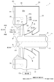
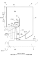
- FIG. 1 is a schematic diagram showing a cross section along an axial direction of a steam turbine according to an embodiment of the present invention
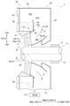
- 13 is a schematic diagram showing a cross section along an axial direction of a steam turbine according to another embodiment.
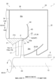
- FIG. FIG. 2 is an enlarged view of a main part of the steam turbine according to the embodiment shown in FIG. 1
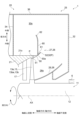
- 3 is an enlarged view of a main part of the steam turbine 1 according to another embodiment of the present invention shown in FIG. 2.
- FIG. 4 is a diagram showing a schematic diagram of a steam flow during rated operation in the steam turbine shown in FIGS. 1 and 3 .
- FIG. 4 is a diagram showing a schematic diagram of a steam flow when the steam turbine shown in FIGS. 1 and 3 is operated at a partial load.
- FIG. 11 is a diagram for explaining conditions (a) and (b).
- FIG. 13 is a diagram for explaining condition (c).
- FIG. 13 is a diagram for explaining condition (d).
- FIG. 13 is a diagram for explaining the angle that a line segment connecting the upstream crossing position and the axial downstream end of the first flow guide forms with respect to the axial direction, and the angle that a line segment connecting the axial upstream end of the inner diffuser and the downstream crossing position forms with respect to the axial direction.
- expressions indicating that things are in an equal state such as “identical,””equal,” and “homogeneous,” not only indicate a state of strict equality, but also indicate a state in which there is a tolerance or a difference to the extent that the same function is obtained.
- expressions describing shapes such as a rectangular shape or a cylindrical shape do not only represent rectangular shapes or cylindrical shapes in the strict geometric sense, but also represent shapes that include uneven portions, chamfered portions, etc., to the extent that the same effect can be obtained.
- the expressions “comprise,””include,””have,””includes,” or “have” of one element are not exclusive expressions excluding the presence of other elements.
- FIG. 1 is a schematic diagram showing a cross section along an axial direction of a steam turbine 1 according to one embodiment.
- FIG. 2 is a schematic diagram showing a cross section along the axial direction of the steam turbine 1 according to another embodiment.
- FIG. 3 is an enlarged view of a main part of the steam turbine 1 according to the embodiment shown in FIG.
- FIG. 4 is an enlarged view of a main part of the steam turbine 1 according to another embodiment shown in FIG.
- a steam turbine 1 is an axial flow turbine. 1 to 4, a steam turbine 1 according to some embodiments includes a turbine rotor (steam turbine rotor) 11 rotatably supported by bearings 6 and rotatable about an axis AX, a casing 20 that covers the turbine rotor 11, and a plurality of stator vane rows 17 fixed to the casing 20.
- the extension direction of the axis AX is referred to as the axial direction or simply the axial direction
- the circumferential direction about the axis AX is simply referred to as the circumferential direction
- the radial direction relative to the axis AX is referred to as the radial direction.
- the direction approaching the axis AX in the radial direction is referred to as the radially inward direction
- the opposite direction is referred to as the radially outward direction.
- the turbine rotor 11 has a rotor shaft 12 that extends axially around the axis AX, and a number of moving blade rows 13 attached to the rotor shaft 12.
- the turbine rotor 11 is supported by bearings 6 so as to be rotatable around the axis AX.
- the multiple moving blade rows 13 are aligned in the axial direction.
- Each moving blade row 13 is composed of a number of moving blades 13b aligned in the circumferential direction.
- the casing 20 has an inner casing 21 and an exhaust chamber 25.
- the inner casing 21 forms an approximately conical space centered on the axis AX and covers the outer periphery of the turbine rotor 11.
- the multiple rotor blade rows 13 of the turbine rotor 11 are arranged in this conical space.
- the multiple stator blade rows 17 are arranged in the axial direction in this conical space.
- Each of the multiple stator blade rows 17 is arranged on the axial upstream side of one of the multiple rotor blade rows 13.
- the multiple stator blade rows 17 are fixed to the inner casing 21 as described above.
- the exhaust chamber 25 has a diffuser 26 and an exhaust casing 30.
- the diffuser 26 is annular with respect to the axis AX, and forms a diffuser space 26s that gradually moves radially outward as it moves downstream along the axis. Steam S flowing out from the final blade row 13e of the turbine rotor 11 flows into the diffuser space 26s.
- the final blade row 13e is the blade row 13 that is located furthest downstream along the axis among the multiple blade rows 13.
- the multiple blades 13b that make up the final blade row 13e are referred to as the final stage blades 13be.
- the diffuser 26 has an outer diffuser (or steam guide, flow guide) 27 that defines the radially outer edge of the diffuser space 26s, and an inner diffuser (or bearing cone) 29 that defines the radially inner edge of the diffuser space 26s.
- the outer diffuser 27 has an annular cross section perpendicular to the axis AX, and gradually widens radially outward as it moves downstream along the axis.
- the inner diffuser 29 also has an annular cross section perpendicular to the axis AX, and gradually widens radially outward as it moves downstream along the axis.
- the outer diffuser 27 is connected to the inner casing 21.
- the exhaust casing 30 has an exhaust port 31.
- This exhaust port 31 opens from the inside radially outward and vertically downward.
- a condenser Co that converts steam S back into water is connected to this exhaust port 31. Therefore, the steam turbine of this embodiment is a downward exhaust type condensing steam turbine. Note that since the steam turbine 1 of this embodiment is a downward exhaust type condensing steam turbine, the lower side of the paper in Figures 1 and 2 is the vertical lower side, and the upper side of the paper in Figures 1 and 2 is the vertical upper side.
- the exhaust casing 30 forms an exhaust space 30s that is connected to the diffuser 26.
- This exhaust space 30s expands around the outer periphery of the diffuser 26 in the circumferential direction relative to the axis AX, and guides the steam S that flows in from the diffuser space 26s to the exhaust port 31.
- the exhaust casing 30 has a downstream casing end plate 32, an upstream casing end plate 34, and a casing outer periphery plate 36.
- the casing downstream end plate 32 defines the axial downstream edge of the exhaust space 30s.
- This casing downstream end plate 32 extends in a direction including a radial component and in the circumferential direction, and is substantially perpendicular to the axis AX.
- the portion of the casing downstream end plate 32 above the axis AX is substantially semicircular.
- the portion of the casing downstream end plate 32 below the axis AX is substantially rectangular.
- a circular opening is formed in the casing downstream end plate 32, with the edge of this circular opening centered on the axis AX.
- the edge of this circular opening forms the radially inner edge of the casing downstream end plate 32.
- the lower edge of this casing downstream end plate 32 forms part of the edge of the exhaust port 31.
- the casing outer peripheral plate 36 defines the radially outer edge of the exhaust space 30s.
- This casing outer peripheral plate 36 is connected to the radially outer edge of the casing downstream end plate 32, and extends in the axial direction and in the circumferential direction centered on the axis AX.
- This casing outer peripheral plate 36 has a semi-cylindrical shape with the upper side forming a semi-cylinder.
- the axial downstream edge of this casing outer peripheral plate 36 is connected to the casing downstream end plate 32.
- the lower edge of this casing outer peripheral plate 36 forms part of the edge of the exhaust port 31.
- the upstream casing end plate 34 defines the axially upstream edge of the exhaust space 30s.
- the upstream casing end plate 34 is disposed axially upstream of the diffuser 26.
- the upstream casing end plate 34 extends radially outward from the outer circumferential surface 21o of the inner casing 21.
- the upstream casing end plate 34 is substantially perpendicular to the axis AX.
- the upstream casing end plate 34 faces the downstream casing end plate 32 with a gap in the axial direction.
- the lower edge of the upstream casing end plate 34 forms part of the edge of the exhaust port 31.
- the radially outer edge of the upstream casing end plate 34 excluding the portion that forms the edge of the exhaust port 31, is connected to the outer casing plate 36.
- the steam turbine 1 is provided with a spray pipe 38 through which a fluid (water) for cooling the rotor blades 13 b can flow.
- the spray pipe 38 is annularly disposed within an axial range from an end 51 on the axial upstream side of the first flow guide 50 to an end 52 on the axial downstream side of the first flow guide 50, and is radially outer than the first flow guide 50 and radially inner than an end 62 on the radial outer side of the second flow guide 60.
- This makes it possible to arrange piping through which fluid for cooling the rotor blades can flow while suppressing the effect on the flow of steam.
- the spray piping 38 is omitted.
- the outer diffuser 27 has a first flow guide 50 extending axially downstream from a position P facing the blade tip 13t of the final stage blade 13be that constitutes the final blade row 13e, and a second flow guide 60 extending radially outward from the first flow guide 50 at an angle different from that of the first flow guide 50.
- the first flow guide 50 is a member having an axial upstream end 51 and an axial downstream end 52, and is formed so that a cross section perpendicular to the axis AX is annular and gradually widens radially outward toward the axial downstream side.
- the axial upstream end 51 of the first flow guide 50 is connected to the inner casing 21.
- the first flow guide 50 has a cross-sectional shape that appears in a virtual plane (e.g., the plane of the paper in Figs. 1 to 4) extending in the axial and radial directions and has a curved surface that is convex toward the inside in the radial direction.
- the first flow guide 50 may have at least a conical surface that gradually widens toward the outside in the radial direction as it approaches the axial downstream side.
- the axial downstream end 52 of the first flow guide 50 is formed to be a separation point 52P formed so that the flow of steam S flowing through the diffuser space 26s separates from the axial downstream end 52.
- the axial downstream end 52 of the first flow guide 50 is connected to a radially inner end 61 of the second flow guide 60, which will be described later.
- the angle difference between the extending direction of the first flow guide 50, which extends toward the axial downstream side and radially outward of the first flow guide 50 near the axial downstream end 52 of the first flow guide 50, and the extending direction of the second flow guide 60, which extends mainly toward the radially inner side near the radially inner end 61 of the second flow guide 60, is relatively large.
- the shape of the surface of the outer diffuser 27 facing the diffuser space 26s, which appears on a virtual plane e.g., the paper surface in Figs.
- the end 52 on the axial downstream side of the first flow guide 50 serves as a separation point 52P formed so that the flow of the steam S flowing through the diffuser space 26s separates from the end 52 on the axial downstream side.
- the separation point 52P faces the diffuser space 26s.
- an R portion having, for example, a certain degree of radius of curvature may be formed from near the axial downstream end 52 of the first flow guide 50 to near the radially inner end 61 of the second flow guide 60.
- the second flow guide 60 has a radially inner end 61 and a radially outer end 62, is an annular member in a cross section perpendicular to the axis AX, and extends primarily in the radial direction.
- the radially inner end 61 is connected to the first flow guide 50 at the axial downstream end 52 of the first flow guide 50.
- the radially inner end 61 is connected to the first flow guide 50 upstream of the axially downstream end 52 of the first flow guide 50.
- the radially inner region 60i of the second flow guide extends in a direction perpendicular to the axis line AX.
- the radially outer region 60o of the second flow guide is curved toward the axial upstream side as it extends radially outward. That is, the second flow guide 60 is located at an axial position of the radially inner end portion 61 and axially upstream of that axial position.
- FIG. 5 is a diagram showing a schematic diagram of the flow of steam S when the steam turbine 1 shown in FIGS. 1 and 3 is operated at rated speed.
- FIGS. 1 and 3 are diagram showing a schematic diagram of the flow of steam S when the steam turbine 1 shown in FIGS. 1 and 3 is operated at a partial load. 5 and 6, the direction of each arrow indicates the direction in which the steam S flows, and the length of each arrow indicates the speed of the flow of the steam S.
- the main flow of steam S that separates from the axial downstream end 52 of the first flow guide 50 becomes a free jet-like flow during rated operation as shown in FIG. 5, providing the same effect as if a diffuser were present axially downstream of the axial downstream end 52 of the first flow guide 50. It was found that this makes it possible to maintain the efficiency of the steam turbine 1 during rated operation.
- the flow of steam S flowing along the surface 50a of the first flow guide 50 is suppressed from generating a relatively high flow velocity near the surface 50a of the first flow guide 50 due to the Coanda effect during partial load operation as shown in FIG. 6.
- FIG. 7 is a diagram for explaining conditions (a) and (b) described later.
- FIG. 8 is a diagram for explaining the condition (c) described later.
- FIG. 9 is a diagram for explaining the condition (d) described later.
- four conditions (a) to (d) that should be satisfied are as follows.
- (a) The axial distance L1 from the axial downstream end 13td of the blade tip 13t of the final stage blade 13be to the axial downstream end 52 of the first flow guide 50 is 20% or more and 45% or less of the blade height h of the final stage blade 13be.
- the radial distance L3 from the axially upstream end 51 of the first flow guide 50 to the axially downstream end 52 of the first flow guide 50 is 200% or more and 300% or less of the radial distance L4 from the intersection position (downstream intersection position) P1 where a perpendicular line (downstream perpendicular line) Lpe1 extending radially inward in a direction perpendicular to the axial direction from the axially downstream end 52 of the first flow guide 50 as a starting point and the inner diffuser 29 intersects with the inner diffuser 29 to the axially upstream end 29a of the inner diffuser 29.
- the area of the annular cross section CS1 perpendicular to the axis AX of the diffuser space 26s at the axial downstream end 52 of the first flow guide 50 is 110% or more and 150% or less of the area of the annular cross section CS2 perpendicular to the axis AX of the diffuser space 26s at the outlet of the final rotor blade row 13e.
- the first flow guide 50 has a relatively simple configuration, making it possible to maintain the efficiency of the steam turbine 1 during rated operation while suppressing a decrease in the efficiency of the steam turbine 1 during partial load operation.
- the steam turbine 1 having the exhaust chamber 25 of some embodiments it is possible to suppress a decrease in the efficiency of the steam turbine 1 during partial load operation while maintaining the efficiency of the steam turbine 1 during rated operation.
- the exhaust chamber 25 may further include the following features.
- the cross-sectional shape of the first flow guide 50 as it appears in a virtual plane extending in the axial and radial directions may have a curved surface that is convex toward the radially inward direction. This makes it easier for the steam S flowing along the surface 50a of the first flow guide 50 to spread radially outward, thereby reducing the pressure loss of the steam S flowing through the diffuser space 26s.
- the distance L5 from the radially inner end 61 to the radially outer end 62 of the second flow guide 60 may be 25% or more and 75% or less of the radial distance L6 from the axially downstream end 52 of the first flow guide 50 to the radially outer wall surface (casing outer plate 36) that defines the radially outer edge of the exhaust space 30s inside the exhaust casing 30.
- the flow of steam S that forms a vortex in the exhaust space 30s axially upstream of the second flow guide 60 is less likely to affect the main flow of steam S flowing along the first flow guide 50, thereby suppressing pressure loss within the exhaust chamber 25.
- the radially outer region 60o of the second flow guide 60 may be curved toward the axial upstream side as it extends radially outward. As a result, the flow of steam S that forms a vortex in the exhaust space 30s axially upstream of the second flow guide 60 is less likely to affect the main flow of steam S flowing along the first flow guide 50, thereby suppressing pressure loss within the exhaust chamber 25.
- the radially inner end 61 of the second flow guide 60 may be connected to the first flow guide 50 at the axially downstream end 52 of the first flow guide 50. This makes it possible to connect the second flow guide 60 to the first flow guide 50 while suppressing the influence on the main flow of steam S that separates from the axial downstream end 52 of the first flow guide 50.
- the radially inner end 61 of the second flow guide 60 may be connected to the first flow guide 50 axially upstream of the axially downstream end 52 of the first flow guide 50. This makes it possible to connect the second flow guide 60 to the first flow guide 50 while suppressing the influence on the main flow of steam S that separates from the axial downstream end 52 of the first flow guide 50.
- the exhaust chamber 25 of the steam turbine 1 comprises a diffuser 26 into which steam S flowing out from the final row of moving blades 13e of the steam turbine rotor (turbine rotor 11) rotating about the axis AX flows in, forming a diffuser space 26s that is annular about the axis AX and gradually expands radially outward about the axis AX as it moves downstream of the axis, and an exhaust casing 30 that has an exhaust port 31 that opens radially outward, is connected to the diffuser space 26s, and expands in the circumferential direction about the axis AX to form an exhaust space 30s that guides the steam S flowing in from the diffuser space 26s to the exhaust port 31.
- the diffuser 26 has an outer diffuser 27 which has an annular cross section perpendicular to the axis AX, gradually widens radially outward toward the axial downstream side, and defines a radially outer edge of a diffuser space 26s, and an inner diffuser 29 which has an annular cross section perpendicular to the axis AX, gradually widens radially outward toward the axial downstream side, and defines a radially inner edge of the diffuser space 26s relative to the axis AX.
- the outer diffuser 27 has a first flow guide 50 which extends axially downstream from a position P facing a blade tip 13t of a final stage rotor blade 13be which constitutes a final rotor blade row 13e, and a second flow guide 60 which extends radially outward from the first flow guide 50 at an angle different from that of the first flow guide 50.
- the first flow guide 50 satisfies at least one of the following conditions.
- An axial distance L1 from an axial downstream end 13td of the blade tip 13t of the final stage blade 13be to an axial downstream end 52 of the first flow guide 50 with respect to the axis AX is 20% or more and 45% or less of a blade height h of the final stage blade 13be.
- the axial distance L2 from the axial downstream end 52 of the first flow guide 50 to the downstream wall surface (casing downstream end plate 32) that defines the axial downstream edge of the exhaust space 30s within the exhaust casing 30 is 100% or more and 150% or less of the blade height h.
- a radial distance L3 with respect to the axis AX from the axially upstream end 51 of the first flow guide 50 to the axially downstream end 52 of the first flow guide 50 is 200% or more and 300% or less of a radial distance L4 from an intersection position (downstream intersection position P1) where a perpendicular line (downstream perpendicular line Lpe1) extending radially inward in a direction perpendicular to the axial direction from the axially downstream end 52 of the first flow guide 50 intersects with the inner diffuser 29 to the axially upstream end 29a of the inner diffuser 29.
- the area of a cross section CS1 perpendicular to the axis AX of the diffuser space 26s at the axial downstream end 52 of the first flow guide 50 is 110% or more and 150% or less of the area of a cross section CS2 perpendicular to the axis AX of the diffuser space 26s at the outlet of the final rotor blade row 13e.
- the above (1A) configuration allows the first flow guide 50, which has a relatively simple configuration, to maintain the efficiency of the steam turbine 1 during rated operation while suppressing a decrease in the efficiency of the steam turbine 1 during partial load operation.
- the cross-sectional shape of the first flow guide 50 as seen in a virtual plane extending in the axial and radial directions may have a curved surface that is convex toward the radially inward direction.
- the above configuration (2A) makes it easier for the steam S flowing along the surface 50a of the first flow guide 50 to spread radially outward, thereby reducing the pressure loss of the steam S flowing through the diffuser space 26s.
- the distance L5 from the radially inner end 61 to the radially outer end 62 of the second flow guide 60 may be 25% or more and 75% or less of the radial distance L6 from the axially downstream end 52 of the first flow guide 50 to the radially outer wall surface (casing outer plate 36) that defines the radially outer edge of the exhaust space 30s inside the exhaust casing 30.
- the flow of steam S that forms a vortex in the exhaust space 30s axially upstream of the second flow guide 60 is less likely to affect the main flow of steam S that flows along the first flow guide 50, so pressure loss in the exhaust chamber 25 can be suppressed.
- the radially outer region 60o of the second flow guide 60 may be curved toward the axial upstream side as it moves radially outward.
- the flow of steam S that forms a vortex in the exhaust space 30s axially upstream of the second flow guide 60 is less likely to affect the main flow of steam S that flows along the first flow guide 50, so pressure loss in the exhaust chamber 25 can be suppressed.
- the radially inner end 61 of the second flow guide 60 may be connected to the first flow guide 50 at the axially downstream end 52 of the first flow guide 50.
- the above configuration (5A) allows the second flow guide 60 to be connected to the first flow guide 50 while suppressing the effect on the main flow of steam S that separates from the axial downstream end 52 of the first flow guide 50.
- the radially inner end 61 of the second flow guide 60 may be connected to the first flow guide 50 axially upstream of the axially downstream end 52 of the first flow guide 50.
- the above configuration (6A) allows the second flow guide 60 to be connected to the first flow guide 50 while suppressing the effect on the main flow of steam S that separates from the axial downstream end 52 of the first flow guide 50.
- a fluid-passing pipe (spray pipe 38) may be provided that is annularly arranged within the axial range from the axial upstream end 51 of the first flow guide 50 to the axial downstream end 52 of the first flow guide 50, radially outer than the first flow guide 50, and radially inner than the radially outer end 62 of the second flow guide 60.
- the above configuration (7A) allows for the arrangement of piping through which fluid can flow while minimizing the impact on the flow of steam S.
- a steam turbine 1 according to at least one embodiment of the present disclosure includes an exhaust chamber 25 of a steam turbine 1 having any of the configurations (1A) to (7A) above, and a steam turbine rotor (turbine rotor 11).
- the above configuration (8A) makes it possible to suppress a decrease in the efficiency of the steam turbine 1 during partial load operation while maintaining the efficiency of the steam turbine 1 during rated operation.
- the radial distance from the intersection position (upstream intersection position) P2 where a perpendicular line (upstream perpendicular line) Lpe2 extending radially outward in a direction perpendicular to the axial direction from the axial upstream end 29a of the inner diffuser 29 as a starting point and intersecting with the first flow guide 50 to the axial downstream end 52 of the first flow guide 50 is defined as distance L8.
- the axial upstream end 29a of the inner diffuser 29 that defines the upstream perpendicular line Lpe2 is the end of the surface of the inner diffuser 29 that faces the diffuser space 26s.
- the upstream intersection position P2 and the axial downstream end 52 of the first flow guide 50 that define the distance L8 are located on the surface of the first flow guide 50 that faces the diffuser space 26s.
- the axial downstream end 52 of the first flow guide 50 which defines the distances L1 to L3 and the distances L5 to L7, is also located on the surface of the first flow guide 50 that faces the diffuser space 26s.
- the distance L4 is the radial distance from the downstream crossing position P1 at which a perpendicular line (downstream perpendicular line) Lpe1 extending radially inward in a direction perpendicular to the axial direction from the axial downstream end 52 of the first flow guide 50 intersects with the inner diffuser 29 to the axial upstream end 29a of the inner diffuser 29.
- the axial downstream end 52 of the first flow guide 50 that defines the downstream perpendicular line Lpe1 is also located on the surface of the first flow guide 50 that faces the diffuser space 26s.
- the downstream crossing position P1 that defines the distance L4 is located on the surface of the inner diffuser 29 that faces the diffuser space 26s.
- the axial upstream end 29a of the inner diffuser 29 that defines the distance L4 is the end of the surface of the inner diffuser 29 that faces the diffuser space 26s.
- the axial distance from the upstream crossing position P2 to the axial downstream end 52 of the first flow guide 50 is defined as a distance L7.
- the distance L7 is also the axial distance from the upstream perpendicular line Lpe2 to the downstream perpendicular line Lpe1.
- the upstream perpendicular line Lpe2 and the downstream perpendicular line Lpe1 are perpendicular lines that appear on an imaginary plane (for example, the plane of the paper in FIG. 8) that extends in the axial and radial directions.
- Condition (e) is as follows.
- the value (L8-L4) obtained by subtracting the distance L4 from the distance L8 is equal to or greater than 35% and equal to or less than 70% of the distance L7, that is, 35% ⁇ (L8-L4)/L7 ⁇ 70%.
- FIG. 10 is a diagram for explaining the angle ⁇ that a line segment connecting the upstream crossing position P2 and the axial downstream end 52 of the first flow guide 50 forms with respect to the axial direction, and the angle ⁇ that a line segment connecting the axial upstream end 29a of the inner diffuser 29 and the downstream crossing position P1 forms with respect to the axial direction.
- the angle difference ( ⁇ ) between the angle ⁇ and the angle ⁇ is an angle equivalent to the opening angle ⁇ between the first flow guide 50 and the inner diffuser 29 in the diffuser 26 .
- a diffuser provided after the final rotor blade row 13e of a steam turbine (hereinafter simply referred to as a diffuser)
- the opening angle ⁇ is large, steam will separate from the diffuser, especially when the steam turbine is operating at a relatively high load. For this reason, the opening angle ⁇ of the diffuser is not made too large.
- the steam S flows over the entire region in the diffuser space 26s between the first flow guide 50 and the inner diffuser 29, as shown in Fig. 5.
- a circulating flow occurs on the axial downstream side, flowing from the radially outer side toward the radially inner side, as shown in a region Rc surrounded by a dashed line in Fig. 6. Therefore, the steam S that has flowed into the diffuser space 26s from the final rotor blade row 13e is affected by this circulating flow and flows in a region upstream of the region Rc in the axial direction. Therefore, by increasing the opening angle ⁇ , the steam S that flows from the final rotor blade row 13e into the diffuser space 26s can flow more easily.
- the flow of steam S along the surface 50a of the first flow guide 50 generates a flow with a relatively high flow velocity near the surface 50a of the first flow guide 50 due to the Coanda effect, and this flow of steam S divides the exhaust space 30s into an axial upstream region and an axial downstream region, thereby suppressing pressure recovery in the exhaust space 30s.
- the above-mentioned separation point 52P is provided on the first flow guide 50 and the opening angle ⁇ is increased.
- the opening angle ⁇ corresponds to the angle difference ( ⁇ - ⁇ ) between the angle ⁇ and the angle ⁇ .
- the angle difference ( ⁇ - ⁇ ) increases, the difference tan ⁇ -tan ⁇ between tan ⁇ , i.e., L8/L7, and tan ⁇ , i.e., L4/L7, i.e., (L8-L4)/L7, increases. Therefore, tan ⁇ -tan ⁇ , i.e., (L8-L4)/L7, can be used as an index of the magnitude of the opening angle ⁇ . Therefore, the above-mentioned condition (e) is a condition regarding the magnitude of the opening angle ⁇ .
- the end 52 on the downstream axial side of the first flow guide 50 is the separation point 52P.
- the diffuser 26 is configured to satisfy the above condition (e). This enables the efficiency of the steam turbine 1 during partial load operation to be further improved compared to the conventional art.
- the physical meaning of (L8-L4)/L7 in condition (e) above is the diffuser opening angle ⁇ , as described above, and is a quantity that represents the diffuser area ratio (i.e., the ratio of the flow area on the upstream side of the diffuser to the flow area on the downstream side of the diffuser) and length ratio (i.e., the ratio of the diffuser length to the characteristic length).
- the numerical range of (L8-L4)/L7 in the above condition (e) is set so that the steam S does not separate from the surface 50a of the first flow guide 50. It is preferable that (L8-L4)/L7 is as large as possible within a range in which the steam S does not separate from the surface 50a of the first flow guide 50. Within the numerical range of (L8-L4)/L7, the upper limit of 70% is set so that, as described above, the steam S does not separate from the surface 50a of the first flow guide 50. In other words, when (L8-L4)/L7 exceeds 70% of the distance L7, the possibility that the steam S will separate from the surface 50a of the first flow guide 50 increases relatively rapidly.
- the lower limit of (L8-L4)/L7 in the above condition (e), 35% is the lower limit of the numerical value required for the diffuser effect to be realized in the diffuser space 26s between the first flow guide 50 and the inner diffuser 29. If (L8-L4)/L7 falls below 35% of the distance L7, the effect of the first flow guide 50 in restricting the flow of steam S from flowing radially outward increases, and there is a risk that the diffuser effect will not be realized.
- the axial distance L1 from the axial downstream end 13td of the blade tip 13t of the final stage blade 13be to the axial downstream end 52 of the first flow guide 50 is made relatively short. 5, during rated operation, the main flow of steam S separated from the axial downstream end 52 of the first flow guide 50 becomes a free jet-like flow, providing the same effect as if a diffuser were present axially downstream of the axial downstream end 52 of the first flow guide 50. Therefore, even if the distance L1 is made relatively short, the efficiency of the steam turbine 1 during rated operation can be maintained.
- the axial distance L1 from the axial downstream end 13td of the blade tip 13t of the final stage blade 13be to the axial downstream end 52 of the first flow guide 50 may be 20% or more and 40% or less of the blade height h of the final stage blade 13be. This allows the efficiency of the steam turbine 1 to be maintained at a relatively high level during operation at a relatively high load.
- the physical meaning of the distance L1 is the length of the diffuser. It is desirable for the distance L1 to be short.
- the distance L1 is related to the numerical range of (L8-L4)/L7 in the above-mentioned condition (e), and it is desirable to have a short distance and a sufficient area ratio within a range that does not cause peeling.
- the lower limit of the distance L1, 20%, is set from this perspective.
- the effective area of the diffuser becomes smaller. If the distance L1 is long, the distance over which the wall surface of the diffuser and the flow of steam S come into contact becomes long, and the friction loss between the wall surface of the diffuser and the flow of steam S becomes large. The upper limit of the distance L1, 40%, is set from this perspective.
- the numerical range of the distance L1 is 30% or more and 40% or less of the blade height h of the final stage rotor blade 13be.
- the physical meaning of the distance L2 is a parameter equivalent to the outlet length of the diffuser. It is desirable to make the distance L2 as large as possible. In consideration of the above-mentioned length ratio, it is desirable to secure an effective area of the diffuser to such an extent that separation of the steam S does not occur within the diffuser. As described above, it is preferable that the distance L2 is large. However, if the distance L2 is too large, separation of the steam S occurs within the diffuser, and the effective area of the diffuser becomes small. Moreover, if the distance L2 is too small, the diffuser will not function.
- the distance L2 should be equal to or greater than 120% and equal to or less than 145% of the blade height h.
- the numerical range of the distance L2 is 130% or more and 140% or less of the blade height h.
- An annular cross section perpendicular to the axis AX of the diffuser space 26s at the axially upstream end 29a of the inner diffuser 29 is defined as a cross section CS3.
- the above-mentioned cross section CS2 is an annular cross section perpendicular to the axis AX of the diffuser space 26s at the outlet of the final rotor blade row 13e, but since the axial positions of the cross sections CS3 and CS2 are very close to each other, they are illustrated at the same location in Fig. 9.
- the axially upstream end 29a of the inner diffuser 29 that defines the cross section CS3 is the end of the surface of the inner diffuser 29 that faces the diffuser space 26s.
- the area of the above-mentioned cross section CS1 i.e., the area of the annular cross section CS1 perpendicular to the axis AX of the diffuser space 26s at the axial downstream end 52 of the first flow guide 50, may be 140% or more and 180% or less of the above-mentioned cross section CS3.
- the above-mentioned range of “140% or more and 180% or less” is a range that is set so that separation of the steam S does not occur within the diffuser 26 .
- the efficiency of the steam turbine 1 during partial load operation can be further improved compared to the conventional art, and the efficiency of the steam turbine 1 during operation at a relatively high load can be maintained at a relatively high level.
- the axial downstream end 52 of the first flow guide 50 that defines the cross section CS1 is also located on the surface of the first flow guide 50 that faces the diffuser space 26s.
- the area of the cross section CS1 is 155% or more and 165% or less of the area of the cross section CS3.
- the distance L5 from the radially inner end 61 to the radially outer end 62 of the second flow guide 60 should be 25% or more and 75% or less of the radial distance L6 from the axially downstream end 52 of the first flow guide 50 to the radially outer wall surface (casing outer plate 36) that defines the radially outer edge of the exhaust space 30s inside the exhaust casing 30.
- the flow of steam S that forms a vortex in the exhaust space 30s axially upstream of the second flow guide 60 is less likely to affect the main flow of steam S flowing along the first flow guide 50, thereby suppressing pressure loss within the exhaust chamber 25.
- the exhaust chamber 25 of the steam turbine 1 comprises a diffuser 26 into which steam S flowing out from the final row of moving blades 13e of the steam turbine rotor (turbine rotor 11) rotating about the axis AX flows in, forming a diffuser space 26s that is annular about the axis AX and gradually expands radially outward about the axis AX as it moves downstream of the axis, and an exhaust casing 30 that has an exhaust port 31 that opens radially outward, is connected to the diffuser space 26s, and expands in the circumferential direction about the axis AX to form an exhaust space 30s that guides the steam S flowing in from the diffuser space 26s to the exhaust port 31.
- the diffuser 26 has an outer diffuser 27 which has an annular cross section perpendicular to the axis AX, gradually widens radially outward toward the axial downstream side, and defines a radially outer edge of a diffuser space 26s, and an inner diffuser 29 which has an annular cross section perpendicular to the axis AX, gradually widens radially outward toward the axial downstream side, and defines a radially inner edge of the diffuser space 26s relative to the axis AX.
- the outer diffuser 27 has a first flow guide 50 which extends axially downstream from a position P facing a blade tip 13t of a final stage rotor blade 13be which constitutes a final rotor blade row 13e, and a second flow guide 60 which extends radially outward from the first flow guide 50 at an angle different from that of the first flow guide 50.
- the axial downstream end 52 of the first flow guide 50 is a separation point 52P formed so that the flow of steam S flowing through the diffuser space 26s separates from the axial downstream end 52.
- the first flow guide 50 has a relatively simple configuration, and the efficiency of the steam turbine 1 during partial load operation can be further improved compared to the conventional configuration.
- the axial distance L1 from the axial downstream end 13td of the blade tip 13t of the final stage blade 13be to the axial downstream end 52 of the first flow guide 50 relative to the axis AX may be 20% to 40% of the blade height h of the final stage blade 13be.
- the above configuration (2B) allows the efficiency of the steam turbine 1 to be maintained at a relatively high level during operation at a relatively high load.
- the axial distance L2 from the axial downstream end 52 of the first flow guide 50 to the downstream wall surface (casing downstream end plate 32) that defines the axial downstream edge of the exhaust space 30s within the exhaust casing 30 may be 120% or more and 145% or less of the blade height h.
- the above configuration (3B) makes it possible to further improve the efficiency of the steam turbine 1 during partial load operation compared to the conventional method, and to maintain a relatively high efficiency during operation at a relatively high load.
- the area of a cross section CS1 perpendicular to the axis AX of the diffuser space 26s at the axial downstream end 52 of the first flow guide 50 may be 140% to 180% of the area of a cross section CS3 perpendicular to the axis AX of the diffuser space 26s at the axial upstream end 29a of the inner diffuser 29.
- the above configuration (4B) makes it possible to further improve the efficiency of the steam turbine 1 during partial load operation compared to conventional methods, and to maintain a relatively high efficiency during operation at a relatively high load.
- the distance L5 from the radially inner end 61 to the radially outer end 62 of the second flow guide 60 may be 25% or more and 75% or less of the radial distance L6 from the axially downstream end 52 of the first flow guide 50 to the radially outer wall surface (casing outer plate 36) that defines the radially outer edge of the exhaust space 30s inside the exhaust casing 30.
- the flow of steam S that forms a vortex in the exhaust space 30s axially upstream of the second flow guide 60 is less likely to affect the main flow of steam S that flows along the first flow guide 50, thereby suppressing pressure loss within the exhaust chamber 25.
- the cross-sectional shape of the first flow guide 50 as seen in a virtual plane extending in the axial and radial directions may have a curved surface that is convex toward the radially inward direction.
- the above configuration (6B) makes it easier for the steam S flowing along the surface 50a of the first flow guide 50 to spread radially outward, thereby reducing the pressure loss of the steam S flowing through the diffuser space 26s.
- the radially outer region 60o of the second flow guide 60 may be curved toward the axial upstream side as it moves radially outward.
- the flow of steam S that forms a vortex in the exhaust space 30s axially upstream of the second flow guide 60 is less likely to affect the main flow of steam S that flows along the first flow guide 50, thereby suppressing pressure loss within the exhaust chamber 25.
- the radially inner end 61 of the second flow guide 60 may be connected to the first flow guide 50 at the axially downstream end 52 of the first flow guide 50.
- the above configuration (8B) allows the second flow guide 60 to be connected to the first flow guide 50 while suppressing the effect on the main flow of steam S that separates from the axial downstream end 52 of the first flow guide 50.
- the radially inner end 61 of the second flow guide 60 may be connected to the first flow guide 50 axially upstream of the axially downstream end 52 of the first flow guide 50.
- the above configuration (9B) allows the second flow guide 60 to be connected to the first flow guide 50 while suppressing the effect on the main flow of steam S that separates from the axial downstream end 52 of the first flow guide 50.
- a fluid-passing pipe (spray pipe 38) may be provided that is annularly arranged within the axial range from the axial upstream end 51 of the first flow guide 50 to the axial downstream end 52 of the first flow guide 50, radially outward from the first flow guide 50 and radially inward from the radially outer end 62 of the second flow guide 60.
- a steam turbine 1 includes an exhaust chamber 25 of a steam turbine 1 having any of the configurations (1B) to (10B) above, and a steam turbine rotor (turbine rotor 11).
- the above (11B) configuration can further improve the efficiency of the steam turbine 1 during partial load operation compared to conventional configurations.
Landscapes
- Engineering & Computer Science (AREA)
- Mechanical Engineering (AREA)
- General Engineering & Computer Science (AREA)
- Turbine Rotor Nozzle Sealing (AREA)
Abstract
Description
本願は、2023年3月15日に日本国特許庁に出願された特願2023-040201号に基づき優先権を主張し、その内容をここに援用する。
例えば特許文献1に記載の蒸気タービンでは、チップフローガイド上半部の端部を下流側に向かって延設することで、ディフューザ長さを従来に比べて長くして、タービン排気損失を低減するようにしている(特許文献1参照)。
軸線を中心として回転する蒸気タービンロータの最終動翼列から流出した蒸気が流入し、前記軸線に対して環状を成し、軸線下流側に向うに連れて次第に前記軸線に対する径方向外側に広がるディフューザ空間を形成するディフューザと、
前記径方向外側に向かって開口する排気口を有し、前記ディフューザ空間に連通し、前記軸線に対する周方向に広がって、前記ディフューザ空間から流入した蒸気を前記排気口に導く排気空間を形成する排気ケーシングと、
を備え、
前記ディフューザは、
前記軸線に対する垂直な断面が環状を成し、前記軸線下流側に向うに連れて次第に前記径方向外側に向かって広がり、前記ディフューザ空間の前記径方向外側の縁を画定する外側ディフューザと、
前記軸線に対する垂直な断面が環状を成し、前記軸線下流側に向うに連れて次第に前記径方向外側に向かって広がり、前記ディフューザ空間の前記軸線に対する径方向内側の縁を画定する内側ディフューザと、
を有し、
前記外側ディフューザは、
前記最終動翼列を構成する最終段動翼の翼端に対向する位置から前記軸線下流側に延在する第1フローガイドと、
前記第1フローガイドとは異なる角度で前記第1フローガイドから前記径方向外側に延在する第2フローガイドと、
を有し、
前記第1フローガイドは、
前記最終段動翼の前記翼端の前記軸線下流側の端部から前記第1フローガイドの前記軸線下流側の端部までの前記軸線に対する軸方向の距離が、前記最終段動翼の翼高さの20%以上45%以下であるか、
前記第1フローガイドの前記軸線下流側の端部から前記排気ケーシングの内、前記排気空間の前記軸線下流側の縁を画定する下流側壁面までの前記軸方向の距離が前記翼高さの100%以上150%以下であるか、
前記第1フローガイドの軸線上流側の端部から前記第1フローガイドの前記軸線下流側の端部までの前記軸線に対する径方向の距離が、前記第1フローガイドの前記軸線下流側の端部を始点として前記軸方向に直交する方向に前記径方向内側へ向かって伸ばした垂線と前記内側ディフューザとが交差する交差位置から前記内側ディフューザの前記軸線上流側の端部までの前記径方向の距離の200%以上300%以下であるか、
前記第1フローガイドの前記軸線下流側の端部における前記ディフューザ空間の前記軸線に対する垂直な断面の面積が、前記最終動翼列の出口における前記ディフューザ空間の前記軸線に対する垂直な断面の面積の110%以上150%以下であるか、
の、少なくとも何れか1つの条件を満たす。
上記(1)の構成の蒸気タービンの排気室と、
前記蒸気タービンロータと、
を備える。
例えば、「ある方向に」、「ある方向に沿って」、「平行」、「直交」、「中心」、「同心」或いは「同軸」等の相対的或いは絶対的な配置を表す表現は、厳密にそのような配置を表すのみならず、公差、若しくは、同じ機能が得られる程度の角度や距離をもって相対的に変位している状態も表すものとする。
例えば、「同一」、「等しい」及び「均質」等の物事が等しい状態であることを表す表現は、厳密に等しい状態を表すのみならず、公差、若しくは、同じ機能が得られる程度の差が存在している状態も表すものとする。
例えば、四角形状や円筒形状等の形状を表す表現は、幾何学的に厳密な意味での四角形状や円筒形状等の形状を表すのみならず、同じ効果が得られる範囲で、凹凸部や面取り部等を含む形状も表すものとする。
一方、一の構成要素を「備える」、「具える」、「具備する」、「含む」、又は、「有する」という表現は、他の構成要素の存在を除外する排他的な表現ではない。
図2は、他の実施形態に係る蒸気タービン1の軸方向に沿った断面を模式的に示す概略図である。
図3は、図1に示す一実施形態に係る蒸気タービン1の要部を拡大した図である。
図4は、図2に示す他の実施形態に係る蒸気タービン1の要部を拡大した図である。
図1から図4に示すように、幾つかの実施形態に係る蒸気タービン1は、軸受6により回転自在に支持され、軸線AXを中心として回転可能なタービンロータ(蒸気タービンロータ)11と、タービンロータ11を覆うケーシング20と、ケーシング20に固定されている複数の静翼列17と、を備えている。なお、以下では、この軸線AXの延在方向を軸線方向又は単に軸方向とし、軸線AXを中心とした周方向を単に周方向とし、軸線AXに対する径方向を径方向とする。さらに、この径方向で軸線AXに近づく方向を径方向内側、その反対方向を径方向外側とする。
これにより、蒸気の流れへの影響を抑制しつつ、動翼の冷却のための流体が流通可能な配管を配置できる。
なお、図3以降の各図では、スプレー配管38の記載を省略している。
幾つかの実施形態に係る外側ディフューザ27は、最終動翼列13eを構成する最終段動翼13beの翼端13tに対向する位置Pから軸線下流側に延在する第1フローガイド50と、第1フローガイド50とは異なる角度で第1フローガイド50から径方向外側に延在する第2フローガイド60と、を有する。
幾つかの実施形態に係る第1フローガイド50は、図3及び図4によく示すように、軸線上流側の端部51と、軸線下流側の端部52とを有し、軸線AXに対する垂直な断面が環状を成し、軸線下流側に向うに連れて次第に径方向外側に向かって広がるように形成された部材である。第1フローガイド50は、軸線上流側の端部51が内側ケーシング21に接続されている。
幾つかの実施形態に係る第1フローガイド50は、軸方向及び径方向に延在する仮想的な平面(例えば、図1から図4における紙面)に表れる第1フローガイド50の断面形状は、径方向内側に向かって凸となる曲面を有している。なお、幾つかの実施形態に係る第1フローガイド50は、少なくとも一部に軸線下流側に向うに連れて次第に径方向外側に向かって広がる円錐面を有していてもよい。
例えば図3に示す例では、第1フローガイド50の軸線下流側の端部52には、第2フローガイド60の後述する径方向内側の端部61が接続されている。しかし、第1フローガイド50の軸線下流側の端部52近傍において第1フローガイド50の軸線下流側且つ径方向外側に向かって延在する第1フローガイド50の延在方向と、第2フローガイド60の径方向内側の端部61近傍において主として径方向内側に向かって延在する第2フローガイド60の延在方向との角度差が比較的大きい。また、軸方向及び径方向に延在する仮想的な平面(例えば、図1から図4における紙面)に表れる、外側ディフューザ27のディフューザ空間26sに面する表面の形状は、第1フローガイド50の軸線下流側の端部52近傍から第2フローガイド60の径方向内側の端部61近傍にかけて比較的急峻に変化している。
このような形状を有することで、幾つかの実施形態に係る第1フローガイド50では、第1フローガイド50の軸線下流側の端部52は、ディフューザ空間26sを流れる蒸気Sの流れが軸線下流側の端部52から剥離するように形成された剥離点52Pとなるようになっている。剥離点52Pは、ディフューザ空間26sに面している。
なお、実質的にディフューザ空間26sを流れる蒸気Sの流れが軸線下流側の端部52から剥離するように形成されていればよいため、第1フローガイド50の軸線下流側の端部52近傍から第2フローガイド60の径方向内側の端部61近傍にかけて、例えばある程度の大きさの曲率半径を有するR部が形成されていてもよい。
幾つかの実施形態に係る第2フローガイド60は、径方向内側の端部61と、径方向外側の端部62とを有し、軸線AXに対する垂直な断面が環状を成し、主として径方向に延在する部材である。
図1及び図3に示す第2フローガイド60では、図3によく示すように、径方向内側の端部61は、第1フローガイド50の軸線下流側の端部52で第1フローガイド50に接続されている。
図2及び図4に示す第2フローガイド60では、図4によく示すように、径方向内側の端部61は、第1フローガイド50の軸線下流側の端部52よりも軸線上流側で第1フローガイド50に接続されている。
幾つかの実施形態に係る第2フローガイド60では、第2フローガイドにおける径方向外側の領域60oは、径方向外側に向かうにつれて軸線上流側に向かうように湾曲している。
すなわち、第2フローガイド60は、径方向内側の端部61における軸方向位置、及び該軸方向位置よりも軸線上流側に位置する。
従来の蒸気タービンでは、部分負荷運転時には、排気室内で剥離や逆流が発生し、排気室内で圧力損失が大きくなり、圧力回復量が低下するという課題があった。
発明者らが鋭意検討した結果、後述する(a)から(d)の4つの条件の少なくとも1つを満たすように第1フローガイド50を構成することで、定格運転時における蒸気タービン1の効率を維持しつつ、従来の蒸気タービンと比較して部分負荷運転時における蒸気タービン1の効率の低下を抑制できることが判明した。
図5は、図1及び図3に示した蒸気タービン1において定格運転を行ったときの蒸気Sの流れを模式的に示した図である。
図6は、図1及び図3に示した蒸気タービン1において部分負荷運転を行ったときの蒸気Sの流れを模式的に示した図である。
図5および図6では、各矢印の向きは蒸気Sが流れる方向を表し、各矢印の長さの長短は、蒸気Sの流速の大小を表す。
図8は、後述する条件(c)について説明するための図である。
図9は、後述する条件(d)について説明するための図である。
図1から図4に示した幾つかの実施形態に係る第1フローガイド50において、何れか1つを満たすことが望まれる(a)から(d)の4つの条件は、次の通りである。
(a)最終段動翼13beの翼端13tの軸線下流側の端部13tdから第1フローガイド50の軸線下流側の端部52までの軸方向の距離L1が、最終段動翼13beの翼高さhの20%以上45%以下である。
例えば幾つかの実施形態に係る排気室25では、上述したように第1フローガイド50は、軸方向及び径方向に延在する仮想的な平面(例えば、図1から図4における紙面)に表れる第1フローガイド50の断面形状は、径方向内側に向かって凸となる曲面を有していてもよい。
これにより、第1フローガイド50の表面50aに沿って流れる蒸気Sが径方向外側に広がっていき易くなるので、ディフューザ空間26sを流れる蒸気Sの圧力損失を低減できる。
これにより、第1フローガイド50に沿って流れる蒸気Sの主たる流れに対して、第2フローガイド60よりも軸線上流側の排気空間30sにおいて渦を形成する蒸気Sの流れが影響を及ぼし難くなるので、排気室25内の圧力損失を抑制できる。
これにより、第1フローガイド50に沿って流れる蒸気Sの主たる流れに対して、第2フローガイド60よりも軸線上流側の排気空間30sにおいて渦を形成する蒸気Sの流れが影響を及ぼし難くなるので、排気室25内の圧力損失を抑制できる。
これにより、第1フローガイド50の軸線下流側の端部52から剥離した主たる蒸気Sの流れへの影響を抑制しつつ第1フローガイド50に第2フローガイド60を接続できる。
これにより、第1フローガイド50の軸線下流側の端部52から剥離した主たる蒸気Sの流れへの影響を抑制しつつ第1フローガイド50に第2フローガイド60を接続できる。
(1A)本開示の少なくとも一実施形態に係る蒸気タービン1の排気室25は、軸線AXを中心として回転する蒸気タービンロータ(タービンロータ11)の最終動翼列13eから流出した蒸気Sが流入し、軸線AXに対して環状を成し、軸線下流側に向うに連れて次第に軸線AXに対する径方向外側に広がるディフューザ空間26sを形成するディフューザ26と、径方向外側に向かって開口する排気口31を有し、ディフューザ空間26sに連通し、軸線AXに対する周方向に広がって、ディフューザ空間26sから流入した蒸気Sを排気口31に導く排気空間30sを形成する排気ケーシング30と、を備える。ディフューザ26は、軸線AXに対する垂直な断面が環状を成し、軸線下流側に向うに連れて次第に径方向外側に向かって広がり、ディフューザ空間26sの径方向外側の縁を画定する外側ディフューザ27と、軸線AXに対する垂直な断面が環状を成し、軸線下流側に向うに連れて次第に径方向外側に向かって広がり、ディフューザ空間26sの軸線AXに対する径方向内側の縁を画定する内側ディフューザ29と、を有する。外側ディフューザ27は、最終動翼列13eを構成する最終段動翼13beの翼端13tに対向する位置Pから軸線下流側に延在する第1フローガイド50と、第1フローガイド50とは異なる角度で第1フローガイド50から径方向外側に延在する第2フローガイド60と、を有する。
第1フローガイド50は、以下の少なくとも何れか1つの条件を満たす。
最終段動翼13beの翼端13tの軸線下流側の端部13tdから第1フローガイド50の軸線下流側の端部52までの軸線AXに対する軸方向の距離L1が、最終段動翼13beの翼高さhの20%以上45%以下である。
第1フローガイド50の軸線下流側の端部52から排気ケーシング30の内、排気空間30sの軸線下流側の縁を画定する下流側壁面(ケーシング下流側端板32)までの軸方向の距離L2が翼高さhの100%以上150%以下である。
第1フローガイド50の軸線上流側の端部51から第1フローガイド50の軸線下流側の端部52までの軸線AXに対する径方向の距離L3が、第1フローガイド50の軸線下流側の端部52を始点として軸方向に直交する方向に径方向内側へ向かって伸ばした垂線(下流側垂線Lpe1)と内側ディフューザ29とが交差する交差位置(下流側交差位置P1)から内側ディフューザ29の軸線上流側の端部29aまでの径方向の距離L4の200%以上300%以下である。
第1フローガイド50の軸線下流側の端部52におけるディフューザ空間26sの軸線AXに対する垂直な断面CS1の面積が、最終動翼列13eの出口におけるディフューザ空間26sの軸線AXに対する垂直な断面CS2の面積の110%以上150%以下である。
例えば、図1から図4に示した幾つかの実施形態に係るディフューザ26を以下の条件(e)を満たすように構成することで、定格運転時における蒸気タービン1の効率を維持しつつ、部分負荷運転時における蒸気タービン1の効率を従来よりも一層向上できることが判明した。
上流側交差位置P2から第1フローガイド50の軸線下流側の端部52までの軸方向の距離を距離L7とする。
なお、距離L7は、上流側垂線Lpe2から下流側垂線Lpe1までの軸方向の距離でもある。
また、上流側垂線Lpe2、及び、下流側垂線Lpe1は、軸方向及び径方向に延在する仮想的な平面(例えば図8における紙面)に表れる垂線である。
(e)距離L8から距離L4を減じた値(L8-L4)は、距離L7の35%以上70%以下、すなわち、35%≦{(L8-L4)/L7}≦70%、である。
以下、条件(e)を満たすことで定格運転時における蒸気タービン1の効率を維持しつつ、部分負荷運転時における蒸気タービン1の効率を従来よりも一層向上できる理由について説明する。
図10は、上流側交差位置P2と第1フローガイド50の軸線下流側の端部52とを結ぶ線分が軸線方向に対してなす角度α、及び、内側ディフューザ29の軸線上流側の端部29aと下流側交差位置P1とを結ぶ線分が軸線方向に対してなす角度βについて説明するための図である。
一般的に蒸気タービンの最終動翼列13e以降に設けるディフューザ(以下、単にディフューザと称する)では、開き角θを大きくしてしまうと、特に蒸気タービンの比較的高負荷での運転時に蒸気がディフューザから剥離してしまう。そのため、ディフューザの開き角θはあまり大きくしない。
したがって、開き角θを大きくすることで最終動翼列13eからディフューザ空間26s内に流入した蒸気Sをより流れ易くすることができる。
したがって、上述した条件(e)は、開き角θの大きさについての条件である。
これにより、部分負荷運転時における蒸気タービン1の効率を従来よりも一層向上できる。
(L8-L4)/L7の数値範囲の内、上限値である70%は、上述したように蒸気Sが第1フローガイド50の表面50aから剥離しないように設定されたものである。すなわち、L8-L4)/L7が距離L7の70%を超えると、蒸気Sが第1フローガイド50の表面50aから剥離する可能性が比較的急激に高まる。
なお、開き角θを大きくしてしまうと、比較的高負荷での運転時に蒸気がディフューザから剥離して蒸気タービン1の効率が大きく損なわれるおそれがある。
そこで、幾つかの実施形態では、最終段動翼13beの翼端13tの軸線下流側の端部13tdから第1フローガイド50の軸線下流側の端部52までの軸方向の距離L1を比較的短くすることとした。
これにより、図5に示すように定格運転時には第1フローガイド50の軸線下流側の端部52から剥離した主たる蒸気Sの流れが自由噴流的な流れとなって、あたかも第1フローガイド50の軸線下流側の端部52よりも軸線下流側にディフューザが存在するのと同様の効果が得られる。よって、上記距離L1を比較的短くしても、定格運転時における蒸気タービン1の効率を維持できる。
これにより、比較的高負荷での運転時における蒸気タービン1の効率を比較的高い効率に維持できる。
距離L1は、上述した条件(e)の(L8-L4)/L7の数値範囲と関連し、短い距離で、剥離を起こさない範囲内で十分な面積比を取ることが望ましい。
距離L1の下限値であるの20%は、このような観点から設定された値である。
距離L1が長いとディフューザの壁面と蒸気Sの流れとが接する距離が長くなり、ディフューザの壁面と蒸気Sの流れとの摩擦損失が大きくなってしまう。
距離L1の上限値であるの40%は、このような観点から設定された値である。
上述した距離L2の物理的意味は、ディフューザの出口長さに相当するパラメータである。距離L2は、できるだけを大きくすることが望ましい。
上述した長さ比との兼ね合いで、ディフューザ内で蒸気Sの剥離が発生しない程度にディフューザの有効面積を確保することが望ましい。
距離L2は、上述したように大きい方がよいが、大きすぎるとディフューザ内で蒸気Sの剥離が発生してディフューザの有効面積が小さくなってしまう。
また、距離L2が小さすぎるとディフューザとして機能しなくなってしまう。
これにより、部分負荷運転時における蒸気タービン1の効率を従来よりも一層向上できるとともに、比較的高負荷での運転時における蒸気タービン1の効率を比較的高い効率に維持できる。
内側ディフューザ29の軸線上流側の端部29aおけるディフューザ空間26sの軸線AXに対する垂直な環状の断面を断面CS3とする。なお、上述した断面CS2は、最終動翼列13eの出口におけるディフューザ空間26sの軸線AXに対する垂直な環状の断面であるが、断面CS3と断面CS2との軸方向位置は極めて接近しているため、図9においては同一箇所に図示している。なお、断面CS3を規定する内側ディフューザ29の軸線上流側の端部29aは、内側ディフューザ29のディフューザ空間26sに面した表面の端部である。
上記の「140%以上180%以下」の範囲は、ディフューザ26内で蒸気Sの剥離が発生しないように設定された範囲である。
これにより、部分負荷運転時における蒸気タービン1の効率を従来よりも一層向上できるとともに、比較的高負荷での運転時における蒸気タービン1の効率を比較的高い効率に維持できる。
なお、断面CS1を規定する第1フローガイド50の軸線下流側の端部52も、第1フローガイド50のディフューザ空間26sに面した表面に位置する。
第2フローガイド60の径方向内側の端部61から径方向外側の端部62までの距離L5は、長すぎると第2フローガイド60よりも軸線上流側の排気空間30sに蒸気Sが供給され難くなってしまう。しかし、距離L5が短すぎると、第1フローガイド50に沿って流れる蒸気Sの主たる流れに対して、第2フローガイド60よりも軸線上流側の排気空間30sにおいて渦を形成する蒸気Sの流れが影響を及ぼし易くなるので、排気室25内の圧力損失が増加してしまう。
これにより、第1フローガイド50に沿って流れる蒸気Sの主たる流れに対して、第2フローガイド60よりも軸線上流側の排気空間30sにおいて渦を形成する蒸気Sの流れが影響を及ぼし難くなるので、排気室25内の圧力損失を抑制できる。
(1B)本開示の少なくとも一実施形態に係る蒸気タービン1の排気室25は、軸線AXを中心として回転する蒸気タービンロータ(タービンロータ11)の最終動翼列13eから流出した蒸気Sが流入し、軸線AXに対して環状を成し、軸線下流側に向うに連れて次第に軸線AXに対する径方向外側に広がるディフューザ空間26sを形成するディフューザ26と、径方向外側に向かって開口する排気口31を有し、ディフューザ空間26sに連通し、軸線AXに対する周方向に広がって、ディフューザ空間26sから流入した蒸気Sを排気口31に導く排気空間30sを形成する排気ケーシング30と、を備える。ディフューザ26は、軸線AXに対する垂直な断面が環状を成し、軸線下流側に向うに連れて次第に径方向外側に向かって広がり、ディフューザ空間26sの径方向外側の縁を画定する外側ディフューザ27と、軸線AXに対する垂直な断面が環状を成し、軸線下流側に向うに連れて次第に径方向外側に向かって広がり、ディフューザ空間26sの軸線AXに対する径方向内側の縁を画定する内側ディフューザ29と、を有する。外側ディフューザ27は、最終動翼列13eを構成する最終段動翼13beの翼端13tに対向する位置Pから軸線下流側に延在する第1フローガイド50と、第1フローガイド50とは異なる角度で第1フローガイド50から径方向外側に延在する第2フローガイド60と、を有する。
第1フローガイド50の軸線下流側の端部52は、ディフューザ空間26sを流れる蒸気Sの流れが軸線下流側の端部52から剥離するように形成された剥離点52Pである。内側ディフューザ29の軸線上流側の端部29aを始点として軸線AXに対する軸方向に直交する方向に径方向外側へ向かって伸ばした上流側垂線Lpe2と第1フローガイド50とが交差する上流側交差位置P2から第1フローガイド50の軸線下流側の端部52までの軸線AXに対する径方向の距離L8、から、第1フローガイド50の軸線下流側の端部52を始点として軸方向に直交する方向に径方向内側へ向かって伸ばした下流側垂線Lpe1と内側ディフューザ29とが交差する下流側交差位置P1から内側ディフューザ29の軸線上流側の端部29aまでの径方向の距離L4、を減じた値は、上流側交差位置P2から第1フローガイド50の軸線下流側の端部52までの軸方向の距離L7の35%以上70%以下である。
11 タービンロータ(蒸気タービンロータ)
13 動翼列
13b 動翼
13be 最終段動翼
13e 最終動翼列
13t 翼端
13td 端部
20 ケーシング
21 内側ケーシング
25 排気室
26 ディフューザ
26s ディフューザ空間
27 外側ディフューザ(スチームガイド、フローガイド)
29 内側ディフューザ(ベアリングコーン)
29a 端部
30 排気ケーシング
30s 排気空間
31 排気口
32 ケーシング下流側端板
36 ケーシング外周板
38 スプレー配管
50 第1フローガイド
50a 表面
51 端部
52 端部
60 第2フローガイド
60i 領域
60o 領域
61 端部
62 端部
Claims (11)
- 軸線を中心として回転する蒸気タービンロータの最終動翼列から流出した蒸気が流入し、前記軸線に対して環状を成し、軸線下流側に向うに連れて次第に前記軸線に対する径方向外側に広がるディフューザ空間を形成するディフューザと、
前記径方向外側に向かって開口する排気口を有し、前記ディフューザ空間に連通し、前記軸線に対する周方向に広がって、前記ディフューザ空間から流入した蒸気を前記排気口に導く排気空間を形成する排気ケーシングと、
を備え、
前記ディフューザは、
前記軸線に対する垂直な断面が環状を成し、前記軸線下流側に向うに連れて次第に前記径方向外側に向かって広がり、前記ディフューザ空間の前記径方向外側の縁を画定する外側ディフューザと、
前記軸線に対する垂直な断面が環状を成し、前記軸線下流側に向うに連れて次第に前記径方向外側に向かって広がり、前記ディフューザ空間の前記軸線に対する径方向内側の縁を画定する内側ディフューザと、
を有し、
前記外側ディフューザは、
前記最終動翼列を構成する最終段動翼の翼端に対向する位置から前記軸線下流側に延在する第1フローガイドと、
前記第1フローガイドとは異なる角度で前記第1フローガイドから前記径方向外側に延在する第2フローガイドと、
を有し、
前記第1フローガイドの前記軸線下流側の端部は、前記ディフューザ空間を流れる前記蒸気の流れが前記軸線下流側の端部から剥離するように形成された剥離点であり、
前記内側ディフューザの軸線上流側の端部を始点として前記軸線に対する軸方向に直交する方向に前記径方向外側へ向かって伸ばした上流側垂線と前記第1フローガイドとが交差する上流側交差位置から前記第1フローガイドの前記軸線下流側の端部までの前記軸線に対する径方向の距離、から、前記第1フローガイドの前記軸線下流側の端部を始点として前記軸方向に直交する方向に前記径方向内側へ向かって伸ばした下流側垂線と前記内側ディフューザとが交差する下流側交差位置から前記内側ディフューザの前記軸線上流側の端部までの前記径方向の距離、を減じた値は、前記上流側交差位置から前記第1フローガイドの前記軸線下流側の端部までの前記軸方向の距離の35%以上70%以下である、
蒸気タービンの排気室。 - 前記最終段動翼の前記翼端の前記軸線下流側の端部から前記第1フローガイドの前記軸線下流側の端部までの前記軸線に対する軸方向の距離は、前記最終段動翼の翼高さの20%以上40%以下である、
請求項1に記載の蒸気タービンの排気室。 - 前記第1フローガイドの前記軸線下流側の端部から前記排気ケーシングの内、前記排気空間の前記軸線下流側の縁を画定する下流側壁面までの前記軸方向の距離は、前記翼高さの120%以上145%以下である、
請求項1又は2に記載の蒸気タービンの排気室。 - 前記第1フローガイドの前記軸線下流側の端部における前記ディフューザ空間の前記軸線に対する垂直な断面の面積は、前記内側ディフューザの前記軸線上流側の端部おける前記ディフューザ空間の前記軸線に対する垂直な断面の面積の140%以上180%以下である、
請求項1又は2に記載の蒸気タービンの排気室。 - 前記第2フローガイドの前記径方向内側の端部から前記径方向外側の端部までの距離は、前記第1フローガイドの前記軸線下流側の端部から前記排気ケーシングの内、前記排気空間の前記径方向外側の縁を画定する径方向外側壁面までの前記径方向の距離の25%以上75%以下である
請求項1又は2に記載の蒸気タービンの排気室。 - 前記軸方向及び前記径方向に延在する仮想的な平面に表れる前記第1フローガイドの断面形状は、前記径方向内側に向かって凸となる曲面を有する、
請求項1又は2に記載の蒸気タービンの排気室。 - 前記第2フローガイドにおける前記径方向外側の領域は、前記径方向外側に向かうにつれて前記軸線上流側に向かうように湾曲している、
請求項1又は2に記載の蒸気タービンの排気室。 - 前記第2フローガイドの前記径方向内側の端部は、前記第1フローガイドの前記軸線下流側の端部で前記第1フローガイドに接続されている、
請求項1又は2に記載の蒸気タービンの排気室。 - 前記第2フローガイドの前記径方向内側の端部は、前記第1フローガイドの前記軸線下流側の端部よりも前記軸線上流側で前記第1フローガイドに接続されている、
請求項1又は2に記載の蒸気タービンの排気室。 - 前記第1フローガイドの前記軸線上流側の端部から第1フローガイドの前記軸線下流側の端部までの前記軸方向の範囲内であって、前記第1フローガイドよりも前記径方向外側、且つ、前記第2フローガイドの前記径方向外側の端部よりも前記径方向内側の領域内に環状に配置された、流体が流通可能な配管、を備える、
請求項1又は2に記載の蒸気タービンの排気室。 - 請求項1又は2に記載の蒸気タービンの排気室と、
前記蒸気タービンロータと、
を備える、
蒸気タービン。
Priority Applications (4)
| Application Number | Priority Date | Filing Date | Title |
|---|---|---|---|
| DE112024000484.9T DE112024000484T5 (de) | 2023-03-15 | 2024-03-13 | Dampfturbinenauslasskammer und Dampfturbine |
| JP2025506891A JPWO2024190810A1 (ja) | 2023-03-15 | 2024-03-13 | |
| KR1020257024209A KR20250124363A (ko) | 2023-03-15 | 2024-03-13 | 증기 터빈의 배기실 및 증기 터빈 |
| CN202480006603.4A CN120418524A (zh) | 2023-03-15 | 2024-03-13 | 蒸汽涡轮的排气室及蒸汽涡轮 |
Applications Claiming Priority (2)
| Application Number | Priority Date | Filing Date | Title |
|---|---|---|---|
| JP2023-040201 | 2023-03-15 | ||
| JP2023040201 | 2023-03-15 |
Publications (1)
| Publication Number | Publication Date |
|---|---|
| WO2024190810A1 true WO2024190810A1 (ja) | 2024-09-19 |
Family
ID=92755222
Family Applications (1)
| Application Number | Title | Priority Date | Filing Date |
|---|---|---|---|
| PCT/JP2024/009696 Ceased WO2024190810A1 (ja) | 2023-03-15 | 2024-03-13 | 蒸気タービンの排気室及び蒸気タービン |
Country Status (5)
| Country | Link |
|---|---|
| JP (1) | JPWO2024190810A1 (ja) |
| KR (1) | KR20250124363A (ja) |
| CN (1) | CN120418524A (ja) |
| DE (1) | DE112024000484T5 (ja) |
| WO (1) | WO2024190810A1 (ja) |
Cited By (1)
| Publication number | Priority date | Publication date | Assignee | Title |
|---|---|---|---|---|
| CN119333250A (zh) * | 2024-12-06 | 2025-01-21 | 中国船舶集团有限公司第七0三研究所 | 一种船用汽轮机高压汽缸导流结构 |
Citations (2)
| Publication number | Priority date | Publication date | Assignee | Title |
|---|---|---|---|---|
| JP2015194085A (ja) * | 2014-03-31 | 2015-11-05 | 株式会社東芝 | 蒸気タービン |
| JP2020186709A (ja) * | 2019-05-17 | 2020-11-19 | 三菱重工業株式会社 | 蒸気タービンの排気室 |
Family Cites Families (1)
| Publication number | Priority date | Publication date | Assignee | Title |
|---|---|---|---|---|
| JP4342840B2 (ja) | 2003-05-30 | 2009-10-14 | 株式会社東芝 | 蒸気タービン |
-
2024
- 2024-03-13 WO PCT/JP2024/009696 patent/WO2024190810A1/ja not_active Ceased
- 2024-03-13 JP JP2025506891A patent/JPWO2024190810A1/ja active Pending
- 2024-03-13 DE DE112024000484.9T patent/DE112024000484T5/de active Pending
- 2024-03-13 KR KR1020257024209A patent/KR20250124363A/ko active Pending
- 2024-03-13 CN CN202480006603.4A patent/CN120418524A/zh active Pending
Patent Citations (2)
| Publication number | Priority date | Publication date | Assignee | Title |
|---|---|---|---|---|
| JP2015194085A (ja) * | 2014-03-31 | 2015-11-05 | 株式会社東芝 | 蒸気タービン |
| JP2020186709A (ja) * | 2019-05-17 | 2020-11-19 | 三菱重工業株式会社 | 蒸気タービンの排気室 |
Cited By (1)
| Publication number | Priority date | Publication date | Assignee | Title |
|---|---|---|---|---|
| CN119333250A (zh) * | 2024-12-06 | 2025-01-21 | 中国船舶集团有限公司第七0三研究所 | 一种船用汽轮机高压汽缸导流结构 |
Also Published As
| Publication number | Publication date |
|---|---|
| JPWO2024190810A1 (ja) | 2024-09-19 |
| DE112024000484T5 (de) | 2025-11-13 |
| KR20250124363A (ko) | 2025-08-19 |
| CN120418524A (zh) | 2025-08-01 |
Similar Documents
| Publication | Publication Date | Title |
|---|---|---|
| JP6334258B2 (ja) | 蒸気タービン | |
| JP6847673B2 (ja) | タービン排気室 | |
| US11149588B2 (en) | Exhaust chamber of steam turbine, flow guide for steam turbine exhaust chamber, and steam turbine | |
| WO2019172422A1 (ja) | ディフューザベーン及び遠心圧縮機 | |
| US11591934B2 (en) | Exhaust hood and steam turbine | |
| JP4848440B2 (ja) | 軸流タービン | |
| US10968759B2 (en) | Rotary machine | |
| CN110959065B (zh) | 蒸汽轮机 | |
| KR20250124363A (ko) | 증기 터빈의 배기실 및 증기 터빈 | |
| US11702962B2 (en) | Steam turbine configured to recover static pressure of steam in diffuser | |
| JP2017008756A (ja) | 軸流タービン | |
| WO2018151158A1 (ja) | 排気ケーシング、及びこれを備える蒸気タービン | |
| JP7368260B2 (ja) | タービン | |
| JP2005233154A (ja) | 蒸気タービン | |
| JP2017061898A (ja) | 蒸気タービン | |
| JP6239258B2 (ja) | 軸流水車 | |
| JP6234343B2 (ja) | 回転機械 | |
| JP6215154B2 (ja) | 回転機械 | |
| JP7527487B2 (ja) | タービン静翼、及び蒸気タービン | |
| JP7433166B2 (ja) | 蒸気タービン排気室及び蒸気タービン | |
| JP6132736B2 (ja) | カプラン水車 | |
| JP7755460B2 (ja) | ベーンドディフューザおよび遠心圧縮機 | |
| JP4782625B2 (ja) | 軸流タービン | |
| KR101811223B1 (ko) | 증기 터빈 | |
| JP2017031947A (ja) | 低圧蒸気タービン構造 |
Legal Events
| Date | Code | Title | Description |
|---|---|---|---|
| 121 | Ep: the epo has been informed by wipo that ep was designated in this application |
Ref document number: 24770915 Country of ref document: EP Kind code of ref document: A1 |
|
| WWE | Wipo information: entry into national phase |
Ref document number: 202480006603.4 Country of ref document: CN |
|
| ENP | Entry into the national phase |
Ref document number: 2025506891 Country of ref document: JP Kind code of ref document: A |
|
| WWE | Wipo information: entry into national phase |
Ref document number: 2025506891 Country of ref document: JP |
|
| ENP | Entry into the national phase |
Ref document number: 1020257024209 Country of ref document: KR Free format text: ST27 STATUS EVENT CODE: A-0-1-A10-A15-NAP-PA0105 (AS PROVIDED BY THE NATIONAL OFFICE) |
|
| WWE | Wipo information: entry into national phase |
Ref document number: 1020257024209 Country of ref document: KR |
|
| WWP | Wipo information: published in national office |
Ref document number: 202480006603.4 Country of ref document: CN |
|
| WWP | Wipo information: published in national office |
Ref document number: 1020257024209 Country of ref document: KR |
|
| WWE | Wipo information: entry into national phase |
Ref document number: 202517079444 Country of ref document: IN |
|
| WWE | Wipo information: entry into national phase |
Ref document number: 112024000484 Country of ref document: DE |
|
| WWP | Wipo information: published in national office |
Ref document number: 202517079444 Country of ref document: IN |
|
| WWP | Wipo information: published in national office |
Ref document number: 112024000484 Country of ref document: DE |
|
| 122 | Ep: pct application non-entry in european phase |
Ref document number: 24770915 Country of ref document: EP Kind code of ref document: A1 |