WO2024190236A1 - 蓄電装置 - Google Patents
蓄電装置 Download PDFInfo
- Publication number
- WO2024190236A1 WO2024190236A1 PCT/JP2024/004916 JP2024004916W WO2024190236A1 WO 2024190236 A1 WO2024190236 A1 WO 2024190236A1 JP 2024004916 W JP2024004916 W JP 2024004916W WO 2024190236 A1 WO2024190236 A1 WO 2024190236A1
- Authority
- WO
- WIPO (PCT)
- Prior art keywords
- exhaust pipe
- membrane member
- energy storage
- flow path
- storage device
- Prior art date
- Legal status (The legal status is an assumption and is not a legal conclusion. Google has not performed a legal analysis and makes no representation as to the accuracy of the status listed.)
- Ceased
Links
Images


Classifications
-
- H—ELECTRICITY
- H01—ELECTRIC ELEMENTS
- H01G—CAPACITORS; CAPACITORS, RECTIFIERS, DETECTORS, SWITCHING DEVICES, LIGHT-SENSITIVE OR TEMPERATURE-SENSITIVE DEVICES OF THE ELECTROLYTIC TYPE
- H01G11/00—Hybrid capacitors, i.e. capacitors having different positive and negative electrodes; Electric double-layer [EDL] capacitors; Processes for the manufacture thereof or of parts thereof
- H01G11/10—Multiple hybrid or EDL capacitors, e.g. arrays or modules
-
- H—ELECTRICITY
- H01—ELECTRIC ELEMENTS
- H01G—CAPACITORS; CAPACITORS, RECTIFIERS, DETECTORS, SWITCHING DEVICES, LIGHT-SENSITIVE OR TEMPERATURE-SENSITIVE DEVICES OF THE ELECTROLYTIC TYPE
- H01G11/00—Hybrid capacitors, i.e. capacitors having different positive and negative electrodes; Electric double-layer [EDL] capacitors; Processes for the manufacture thereof or of parts thereof
- H01G11/78—Cases; Housings; Encapsulations; Mountings
-
- H—ELECTRICITY
- H01—ELECTRIC ELEMENTS
- H01M—PROCESSES OR MEANS, e.g. BATTERIES, FOR THE DIRECT CONVERSION OF CHEMICAL ENERGY INTO ELECTRICAL ENERGY
- H01M50/00—Constructional details or processes of manufacture of the non-active parts of electrochemical cells other than fuel cells, e.g. hybrid cells
- H01M50/20—Mountings; Secondary casings or frames; Racks, modules or packs; Suspension devices; Shock absorbers; Transport or carrying devices; Holders
- H01M50/204—Racks, modules or packs for multiple batteries or multiple cells
- H01M50/207—Racks, modules or packs for multiple batteries or multiple cells characterised by their shape
- H01M50/209—Racks, modules or packs for multiple batteries or multiple cells characterised by their shape adapted for prismatic or rectangular cells
-
- H—ELECTRICITY
- H01—ELECTRIC ELEMENTS
- H01M—PROCESSES OR MEANS, e.g. BATTERIES, FOR THE DIRECT CONVERSION OF CHEMICAL ENERGY INTO ELECTRICAL ENERGY
- H01M50/00—Constructional details or processes of manufacture of the non-active parts of electrochemical cells other than fuel cells, e.g. hybrid cells
- H01M50/30—Arrangements for facilitating escape of gases
- H01M50/342—Non-re-sealable arrangements
-
- H—ELECTRICITY
- H01—ELECTRIC ELEMENTS
- H01M—PROCESSES OR MEANS, e.g. BATTERIES, FOR THE DIRECT CONVERSION OF CHEMICAL ENERGY INTO ELECTRICAL ENERGY
- H01M50/00—Constructional details or processes of manufacture of the non-active parts of electrochemical cells other than fuel cells, e.g. hybrid cells
- H01M50/30—Arrangements for facilitating escape of gases
- H01M50/35—Gas exhaust passages comprising elongated, tortuous or labyrinth-shaped exhaust passages
- H01M50/367—Internal gas exhaust passages forming part of the battery cover or case; Double cover vent systems
Definitions
- the present invention relates to an electricity storage device.
- Patent Document 1 discloses a battery module having a single cell, a housing, an exhaust duct, and a valve.
- the exhaust duct has a first opening and a second opening having a larger area than the first opening.
- the first opening is connected to the opening of the housing.
- the valve is an electromagnetic valve, and is provided on the side of the exhaust duct close to the second opening.
- the valve (solenoid valve) is operated using the detection results of a temperature sensor or pressure sensor, etc.
- a temperature sensor or pressure sensor etc.
- the present invention was made by the inventors by focusing on the above-mentioned problem, and aims to provide a power storage device with improved reliability.
- An energy storage device comprises an energy storage element, an outer casing that houses the energy storage element, an exhaust pipe that is provided on the outer casing and forms a gas flow path, and a membrane member that blocks the flow path, wherein the exhaust pipe has an opposing portion that faces the membrane member, and the opposing portion is joined to the membrane member, and at least a recess is formed in the opposing portion, or a convex portion is formed in the opposing portion and the membrane member is joined to a tip portion of the convex portion, or the flow path is formed inside the opposing portion, and the opposing portion has an inclined surface that is not perpendicular to the direction of the flow path on the inside.
- the present invention provides a power storage device with improved reliability.
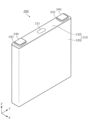
- FIG. 1 is a perspective view showing the appearance of the electricity storage device according to the first embodiment.
- FIG. 2 is an exploded perspective view of the electricity storage device according to the first embodiment.
- FIG. 3 is a perspective view showing the configuration of the energy storage element according to the first embodiment.
- FIG. 4 is a perspective view showing the appearance of the exhaust pipe according to the first embodiment.
- FIG. 5 is a cross-sectional view showing the configuration of the exhaust pipe and its surroundings according to the first embodiment.
- FIG. 6 is a cross-sectional view showing a cross section of the end portion of the exhaust pipe and the membrane member according to the first embodiment.
- FIG. 7 is a perspective view showing the range of arrangement of an adhesive layer of a film member.
- FIG. 8 is a front view showing a joining area with the membrane member in the facing portion according to the first embodiment.
- FIG. 9 is a front view of an exhaust pipe according to a first modification of the first embodiment.
- FIG. 10 is a front view of an exhaust pipe according to the second modification of the first embodiment.
- FIG. 11 is a cross-sectional view showing a cross section of an end portion of an exhaust pipe and a membrane member according to a third modification of the first embodiment.
- FIG. 12 is a perspective view showing the appearance of an exhaust pipe according to the second embodiment.
- FIG. 13 is a cross-sectional view showing the configuration of an exhaust pipe and its surroundings according to the second embodiment.
- FIG. 14 is a front view showing a joining area with a membrane member in an opposing portion according to the second embodiment.
- FIG. 15 is a front view showing a joining area with a membrane member in an opposing portion according to a first modification of the second embodiment.
- FIG. 16 is a perspective view showing the appearance of an exhaust pipe according to the third embodiment.
- FIG. 17 is a cross-sectional view showing the configuration of an exhaust pipe and its surroundings according to the third embodiment.
- FIG. 18 is a perspective view showing the appearance of an exhaust pipe according to a first modification of the third embodiment.
- FIG. 19 is a cross-sectional view showing the configuration of an exhaust pipe and its surroundings according to a first modification of the third embodiment.
- FIG. 20A is a cross-sectional view showing a membrane member disposed at an end of an exhaust pipe facing the inside of an exterior body.
- FIG. 20B is a cross-sectional view showing a membrane member disposed inside the exhaust pipe.
- An energy storage device comprises an energy storage element, an exterior body that houses the energy storage element, an exhaust pipe that is provided in the exterior body and forms a gas flow path, and a membrane member that blocks the flow path, the exhaust pipe has an opposing portion that faces the membrane member, the opposing portion is joined to the membrane member, and at least a recess is formed in the opposing portion, or a convex portion is formed in the opposing portion and the membrane member is joined to a tip portion of the convex portion, or the flow path is formed inside the opposing portion, and the opposing portion has an inclined surface that is not perpendicular to the direction of the flow path on the inside.
- the joint area between the film member that blocks the gas flow path and the opposing portion of the exhaust pipe can be adjusted by at least one of increasing or decreasing the opening area of the recess, increasing or decreasing the area of the tip of the protrusion, changing the angle of the inclined surface of the opposing portion, or increasing or decreasing the proportion of the inclined surface in the opposing portion.
- the film member can suppress the intrusion of foreign matter through the exhaust pipe.
- the pressure of the gas can be used to peel the film member off from the exhaust pipe.
- the gas inside the exterior body is guided to an appropriate position through the exhaust pipe.
- the energy storage device according to this embodiment is an energy storage device with improved reliability.
- the recess may be formed in the opposing portion.
- the joint area between the film member that blocks the gas flow path and the opposing portion of the exhaust pipe can be adjusted by increasing or decreasing the opening area of the recess.
- the film member can suppress the intrusion of foreign matter through the exhaust pipe.
- the gas pressure can be used to peel the film member off from the exhaust pipe.
- the gas inside the exterior body is guided to an appropriate position via the exhaust pipe.
- the energy storage device according to this embodiment is an energy storage device with improved reliability.
- the flow path may be formed inside the exhaust pipe, and the recess may surround the inside.
- the recess forms a series of grooves that surround the inside of the exhaust pipe, so that the bonding area between the membrane member and the opposing portion can be made approximately uniform in the circumferential direction of the exhaust pipe. This further improves the reliability of the bonding between the membrane member and the opposing portion, and as a result, the membrane member's function of preventing the intrusion of foreign matter under normal conditions is more reliably maintained.
- the opposing portion may be formed with a convex portion, and the film member may be joined to the tip of the convex portion.
- the bonding area between the film member that blocks the gas flow path and the opposing portion can be adjusted by increasing or decreasing the area of the tip of the convex portion.
- the film member can suppress the intrusion of foreign matter through the exhaust pipe.
- the gas pressure can be used to peel the film member off from the exhaust pipe.
- the gas inside the exterior body is guided to an appropriate position through the exhaust pipe.
- the energy storage device according to this embodiment is an energy storage device with improved reliability.
- the flow path may be formed inside the exhaust pipe, and the protrusion may surround the inside.
- the protrusions form a series of walls that surround the inside of the exhaust pipe, so the joint area between the membrane member and the opposing portion can be made approximately uniform in the circumferential direction of the exhaust pipe. This further improves the reliability of the joint between the membrane member and the opposing portion. As a result, the function of the membrane member to suppress the intrusion of foreign matter under normal conditions is more reliably maintained.
- the flow path may be formed on the inner side of the opposing portion, and the opposing portion may have an inclined surface that is not perpendicular to the direction of the flow path on the inner side.
- the joint area between the film member that blocks the gas flow path and the opposing portion of the exhaust pipe can be adjusted by changing the angle of the inclined surface of the opposing portion, or by increasing or decreasing the proportion of the inclined surface in the opposing portion.
- the film member can suppress the intrusion of foreign matter through the exhaust pipe.
- the gas pressure can be used to peel the film member off from the exhaust pipe.
- the gas inside the exterior body is guided to an appropriate position via the exhaust pipe.
- the energy storage device according to this embodiment is an energy storage device with improved reliability.
- the arrangement direction of multiple energy storage elements is defined as the X-axis direction.
- the arrangement direction of a pair of terminals (positive and negative) in one energy storage element, or the direction in which the short sides of the container of one energy storage element face each other is defined as the Y-axis direction.
- the arrangement direction of the main body and lid of the exterior body of the energy storage device, or the arrangement direction of the main body and lid of the container of the energy storage element is defined as the Z-axis direction.
- the positive X-axis direction refers to the direction of the arrow on the X-axis
- the negative X-axis direction refers to the opposite direction to the positive X-axis direction.
- the X-axis direction it refers to both or either of the positive and negative X-axis directions.
- the Y-axis and Z-axis directions may also include cases where the directions or attitudes are not strictly the same.
- two directions being parallel not only means that the two directions are completely parallel, but also means that the directions are substantially parallel, that is, that there is a difference of, for example, about several percent.
- the term "insulation” it means “electrical insulation”. It is preferable that the insulating material is formed from a material having a volume resistivity of 1 ⁇ 10 10 ⁇ m or more.
- Fig. 1 is a perspective view showing the external appearance of a power storage device 10 according to embodiment 1.
- Fig. 2 is an exploded perspective view of the power storage device 10 according to embodiment 1.
- the power storage device 10 is a device that can charge electricity from the outside and discharge electricity to the outside.
- the power storage device 10 has a substantially rectangular parallelepiped shape.
- the rectangular parallelepiped here means a hexahedron with all faces being rectangular or square.
- the power storage device 10 is, for example, a battery module (battery assembly) used for power storage or power supply purposes.
- the power storage device 10 is used as a battery for driving or starting the engine of a moving body such as an automobile, a motorcycle, a watercraft, a ship, a snowmobile, an agricultural machine, a construction machine, an automatic guided vehicle (AGV), or a railway car for an electric railway.
- AGV automatic guided vehicle
- Examples of the above-mentioned automobiles include electric vehicles (EVs), hybrid electric vehicles (HEVs), plug-in hybrid electric vehicles (PHEVs), and fossil fuel (gasoline, diesel, liquefied natural gas, etc.) automobiles.
- Examples of the above-mentioned electric railway vehicles include electric trains, monorails, linear motor cars, and hybrid trains equipped with both diesel engines and electric motors.
- the power storage device 10 can also be used as a stationary battery for home or business use.
- the energy storage device 10 includes an exterior body 100. As shown in FIG. 2, the exterior body 100 contains a plurality of energy storage elements 200, a bus bar holder 300, and a bus bar 400. In addition to the above components, the energy storage device 10 may also include spacers or cell holders arranged along each of the plurality of energy storage elements 200, restraining members that restrain the plurality of energy storage elements 200, and a circuit board that monitors or controls the charging and discharging states of the plurality of energy storage elements 200.
- the exterior body 100 is a box-shaped (approximately rectangular parallelepiped) container (module case) that constitutes the housing (outer shell) of the energy storage device 10.
- the exterior body 100 is disposed outside the multiple energy storage elements 200, the bus bar holder 300, and the bus bar 400, and protects the energy storage elements 200, etc.
- the exterior body 100 is formed from an insulating material such as polycarbonate (PC), polypropylene (PP), polyethylene (PE), polystyrene (PS), polyphenylene sulfide resin (PPS), polyphenylene ether (PPE (including modified PPE)), polyethylene terephthalate (PET), polybutylene terephthalate (PBT), polyether ether ketone (PEEK), tetrafluoroethylene perfluoroalkyl vinyl ether (PFA), polytetrafluoroethylene (PTFE), polyether sulfone (PES), polyamide (PA), ABS resin, or a composite material thereof, or a metal with an insulating coating.
- PC polycarbonate
- PP polypropylene
- PE polyethylene
- PS polystyrene
- PPS polyphenylene sulfide resin
- PPE polyphenylene ether
- PPE polyphenylene ether
- PFA tetrafluoroethylene perflu
- the exterior body 100 has an exterior body main body 110 that constitutes the main body of the exterior body 100, and a lid body 120 that closes the opening of the exterior body 100.
- the exterior body main body 110 is a housing (casing) with an opening formed therein, and contains the energy storage element 200 and the like.
- the lid body 120 is joined to the exterior body main body 110 by adhesive, heat sealing (thermal welding), ultrasonic welding, laser welding, screw connection, or the like.
- the exterior body 100 has a structure in which the inside is sealed (sealed) (excluding the exhaust pipe 150 described later).
- the lid body 120 is provided with a positive external terminal 121 and a negative external terminal 122.
- the energy storage device 10 charges with electricity from the outside and discharges electricity to the outside via the positive external terminal 121 and the negative external terminal 122.
- the exterior body 100 includes an exhaust pipe 150.
- the exhaust pipe 150 is disposed in the cover body 120.
- the exhaust pipe 150 forms a gas flow path 250 (described later with reference to FIG. 5) when gas is discharged from the energy storage element 200.
- a film member 160 that blocks the gas flow path 250 is disposed in the exhaust pipe 150.
- the film member 160 has air permeability.
- a pipe member such as a gas hose (not shown) is connected to the exhaust pipe 150. The gas discharged from the exhaust pipe 150 is guided to a predetermined position through the pipe member.
- the configuration of the exhaust pipe 150 and its surroundings will be described later with reference to FIGS. 4 to 8.
- the storage element 200 is a secondary battery (single cell), and more specifically, a non-aqueous electrolyte secondary battery such as a lithium ion secondary battery.
- the storage element 200 has a flattened rectangular parallelepiped shape (angle), and in this embodiment, eight storage elements 200 are arranged in the X-axis direction.
- the size, shape, and number of storage elements 200 arranged are not limited.
- the storage element 200 may be a cylindrical shape (cylinder shape), an elongated cylindrical shape, an elliptical cylindrical shape, or the like, and only one storage element 200 may be arranged.
- the storage element 200 is not limited to a non-aqueous electrolyte secondary battery, and may be a secondary battery other than a non-aqueous electrolyte secondary battery, or may be a capacitor.
- the storage element 200 may be a primary battery instead of a secondary battery.
- the storage element 200 may be a battery using a solid electrolyte.
- the storage element 200 may be a pouch-type storage element. The detailed configuration of the energy storage element 200 will be described later with reference to FIG. 3.
- the busbar holder 300 is a flat, rectangular member (also called a busbar frame or busbar plate) that insulates the busbar 400 from other members and regulates the position of the busbar 400.
- the busbar holder 300 is provided with a number of busbar openings 317 that expose a portion of each of the multiple busbars 400 toward the multiple energy storage elements 200.
- a path forming portion 319 is provided at the center of the bus bar holder 300 in the Y-axis direction, which extends in the X-axis direction and protrudes in the positive direction of the Z-axis along the arrangement of the gas exhaust valves 231 of the multiple storage elements 200.
- the path forming portion 319 forms an exhaust path for gas exhausted from the storage elements 200 along the X-axis direction.
- path outlets 318 are provided at both ends of the longitudinal direction of the path forming portion 319. Gas exhausted from the storage elements 200 preferentially passes through the path outlets 318 and is discharged to the outside of the exterior body 100 via the exhaust pipe 150.
- the bus bar holder 300 configured in this manner is fixed to the exterior body main body 110 of the exterior body 100 by a predetermined method such as adhesion or heat welding.
- the bus bar 400 is a plate-shaped member connected to the energy storage elements 200.
- the bus bar 400 is disposed above the energy storage elements 200 and is connected (joined) to the terminals 240 of the energy storage elements 200.
- the bus bar 400 is formed of a conductive metal member such as aluminum, aluminum alloy, copper, copper alloy, nickel, etc., or a combination of these, or a conductive member other than a metal.
- the busbar 400 includes busbars 410 and 420, and three busbars 430.
- the three busbars 430 connect two energy storage elements 200 in parallel to form four sets of energy storage element groups, and connect the four sets of energy storage element groups in series.
- the busbar 410 is joined to the positive terminals of two energy storage elements 200 arranged at the end of the energy storage element group in the positive direction of the X-axis, and is electrically connected to the positive external terminal 121.
- the busbar 420 is joined to the negative terminals of two energy storage elements 200 arranged at the end of the energy storage element group in the negative direction of the X-axis, and is electrically connected to the negative external terminal 122.
- the electrical connection form of the multiple energy storage elements 200 is not particularly limited, and the multiple energy storage elements 200 may be connected in series and/or parallel in any combination.
- FIG. 3 is a perspective view showing the configuration of the energy storage element 200 according to the first embodiment.
- the energy storage element 200 includes a container 210, a pair of terminals 240 (positive and negative electrodes, the same below), and an upper gasket 242.
- the container 210 contains a lower gasket, an electrode body, a pair of current collectors, and an electrolytic solution (non-aqueous electrolyte), but these are not shown.
- the electrolytic solution there is no particular limit to the type as long as it does not impair the performance of the energy storage element 200, and various types can be selected.
- the energy storage element 200 may have a spacer disposed on the side or below the electrode body, an insulating film that wraps the electrode body, etc. Furthermore, an insulating film (shrink tube, etc.) that covers the outer surface of the container 210 may be disposed around the container 210.
- the container 210 is a rectangular parallelepiped (angular or box-shaped) case having a container body 220 with an opening and a cover plate 230 that closes the opening of the container body 220.
- the container body 220 is a rectangular cylindrical member with a bottom that constitutes the main body of the container 210, and has an opening in the positive direction of the Z axis.
- the container body 220 has a pair of long sides on both sides in the X axis direction, a pair of short sides on both sides in the Y axis direction, and a bottom surface in the negative direction of the Z axis.
- the cover plate 230 is provided with a gas exhaust valve 231 that releases pressure when the pressure inside the container 210 rises excessively, and a liquid injection section (not shown) for injecting electrolyte into the container 210.
- a gas exhaust valve 231 that releases pressure when the pressure inside the container 210 rises excessively
- a liquid injection section (not shown) for injecting electrolyte into the container 210.
- the terminal 240 is a terminal member (positive electrode terminal or negative electrode terminal) of the energy storage element 200 that is disposed on the cover plate 230.
- the terminal 240 is electrically connected to the positive electrode plate or negative electrode plate of the electrode body via a current collector.
- the terminal 240 is formed of aluminum, an aluminum alloy, copper, a copper alloy, or the like.
- the electrode body is a storage element (power generating element) formed by stacking a positive electrode plate, a negative electrode plate, and a separator.
- the positive electrode plate is a current collector foil made of a metal such as aluminum or an aluminum alloy, on which a positive electrode active material layer is formed.
- the negative electrode plate is a current collector foil made of a metal such as copper or a copper alloy, on which a negative electrode active material layer is formed.
- any known material can be used as long as it can absorb and release lithium ions.
- the separator can be a microporous sheet or nonwoven fabric made of resin.
- the electrode body is formed by stacking the electrode plates (positive electrode plate and negative electrode plate) in the X-axis direction.
- the electrode body may be of any shape, such as a wound type electrode body formed by winding the electrode plates (positive electrode plate and negative electrode plate), a stack type electrode body formed by stacking multiple flat electrode plates, or a bellows type electrode body in which the electrode plates are folded in a bellows shape.
- the current collectors are conductive members (positive and negative current collectors) electrically connected to the terminal 240 and the electrode body.
- the positive current collector is made of aluminum or an aluminum alloy, etc., like the current collector foil of the positive electrode plate
- the negative current collector is made of copper or a copper alloy, etc., like the current collector foil of the negative electrode plate.
- the upper gasket 242 is a gasket that is disposed between the cover plate 230 and the terminal 240 and insulates and seals between the cover plate 230 and the terminal 240.
- the lower gasket is a gasket that is disposed between the cover plate 230 and the current collector and insulates and seals between the cover plate 230 and the current collector.
- the upper gasket 242 and the lower gasket may be made of any material as long as they have insulating properties.
- the exterior body 100 is composed of the lid body 120 and the exterior body main body 110, and the joint between these two members is joined by adhesion or welding so that the inside of the exterior body 100 is sealed (sealed) as described above. This prevents foreign matter such as water from entering through the joint between the lid body 120 and the exterior body main body 110.
- the pressure difference between the inside and outside of the exterior body 100 is likely to increase due to changes in the external environment (atmospheric pressure or temperature) of the exterior body 100. This can cause damage or deterioration of the exterior body 100.
- the exterior body 100 has an exhaust pipe 150, and the exhaust pipe 150 is blocked by a breathable film member 160.
- This film member 160 prevents foreign matter from entering the interior of the exterior body 100 via the exhaust pipe 150.
- the film member 160 is breathable, air can move from one side of the exterior body 100 to the other side via the exhaust pipe 150. This ensures pressure balance between the interior and exterior of the exterior body 100 under normal conditions.
- gas exhaust valve 231 is opened (valve open) due to an excessive increase in the internal pressure of the container 210 of the energy storage element 200, high-temperature and high-pressure gas is exhausted from the gas exhaust valve 231 into the exterior body 100.
- the high-temperature gas may increase the temperature of other energy storage elements 200.
- gas may leak from an unexpected position in the exterior body 100. Therefore, it is important to quickly exhaust the gas exhausted from the energy storage element 200 to the outside of the exterior body 100 from the exhaust pipe 150 from the viewpoint of suppressing the spread of adverse effects when the energy storage element 200 is opened.
- the energy storage device 10 is configured so that when gas is discharged from the energy storage element 200, a gas flow path 250 is formed that connects the inside and outside of the exterior body 100.
- a gas flow path 250 is formed that connects the inside and outside of the exterior body 100.
- the film member 160 that blocks the gas flow path 250 in the exhaust pipe 150 peels off from the exhaust pipe 150 to open the gas flow path 250.
- the gas inside the exterior body 100 is discharged to the outside of the exterior body 100 via the exhaust pipe 150.
- the configuration of the exhaust pipe 150 and its surroundings will be described in detail below with reference to Figures 4 to 8.
- FIG. 4 is a perspective view showing the appearance of the exhaust pipe 150 according to the first embodiment.
- the membrane member 160 is shown in a state separated from the exhaust pipe 150.
- the approximate range of the opposing portion 153 which is the portion of the exhaust pipe 150 that faces the membrane member 160, is shown by a circular dotted line.
- FIG. 5 is a cross-sectional view showing the exhaust pipe 150 according to the first embodiment and the configuration of its surroundings. In FIG. 5, a cross-section of a portion of the energy storage device 10 in the XZ plane parallel to the V-V line in FIG. 1 is simply shown.
- the bus bar holder 300 and the bus bar 400 are omitted, and one of the multiple energy storage elements 200 is shown in schematic form.
- the arrangement of hollow arrows in FIG. 5 represents the gas flow path 250 when gas is discharged from the energy storage element 200.
- the gas flow path 250 shown in FIG. 5 does not take into account the presence of the bus bar holder 300, but even if the bus bar holder 300 is arranged, the gas flow path 250 is formed from the energy storage element 200 through the path exit 318 (see FIG. 2) of the path forming portion 319 to the outside of the exhaust pipe 150.
- FIG. 6 is a cross-sectional view showing a cross section of the end portion 159 of the exhaust pipe 150 and the membrane member 160 according to the first embodiment.
- the position of the cross section in FIG. 6 corresponds to the position of the cross section in FIG. 5.
- FIG. 7 is a perspective view showing the arrangement range of the adhesive layer 190 of the membrane member 160. In FIG. 7, the approximate arrangement range of the adhesive layer 190 is represented by a patterned area.
- FIG. 8 is a front view (viewed from the positive direction of the X-axis) showing the joining range with the membrane member 160 at the opposing portion 153 according to the first embodiment. In FIG. 8, the joining ranges 153a and 153b are represented by patterned areas.
- the exhaust pipe 150 is provided integrally with the cover 120 of the exterior body 100 as shown in FIG. 5.
- the cover 120 with the exhaust pipe 150 integrally formed therewith is produced by resin molding using a mold.
- the exhaust pipe 150 may be produced as a separate member from the exterior body 100.
- the exhaust pipe 150 and the exterior body 100 may be joined by adhesion, welding, screw connection, press fitting, or the like.
- the exhaust pipe 150 may be attached to the exterior body 100 by rotating the exhaust pipe 150 having a male thread on its outer circumferential surface into a through hole provided in the exterior body 100 and having a female thread formed on its inner circumferential surface.
- a sealant such as an O-ring may be placed at the joint.
- the exhaust pipe 150 is integral with the exterior body 100 or is a separate component provided on the exterior body 100, when the term "outside the exterior body 100" is used, it means the outside of the exterior body 100 including the exhaust pipe 150.
- a film member 160 that blocks the gas flow path 250 is disposed at the end 159 of the exhaust pipe 150 that faces the outside of the exterior body 100.
- the end 159 of the exhaust pipe 150 is the part that is located farthest from the exterior body 100 when the exhaust pipe 150 is divided into three parts in the tube axis direction (X-axis direction).
- the end 159 of the exhaust pipe 150 is the part that corresponds to 1/3 of the length L of the exhaust pipe 150 (see FIG. 5) from the edge of the exhaust pipe 150 in the positive direction of the X-axis.
- the end 159 of the exhaust pipe 150 may be expressed as the downstream end 159 of the gas flow path 250. Supplementary information regarding the end 159 also applies to the ends 179 and 189 in the second and third embodiments described below.
- the exhaust pipe 150 has an opposing portion 153 that faces the membrane member 160 and is joined to the membrane member 160.
- the opposing portion 153 is provided on the end surface of the end portion 159 of the exhaust pipe 150.
- an exhaust port 151 which is an outlet for gas, is present in the center of the opposing portion 153.
- a gas flow path 250 is formed inside the exhaust port 151, i.e., on the inside 152 of the exhaust pipe 150.
- the membrane member 160 has an adhesive layer 190 on the surface upstream of the gas flow path 250 (negative direction of the X-axis, the same below).
- the adhesive layer 190 is also called, for example, an "adhesive layer".
- materials for the adhesive layer 190 include acrylic adhesives and silicone adhesives.
- the membrane member 160 is bonded to the opposing portion 153 of the exhaust pipe 150 via the adhesive layer 190. As a result, the membrane member 160 blocks the gas flow path 250. "Clogging the gas flow path 250" does not require completely stopping (blocking) the flow of gas.
- the membrane member 160 has a degree of breathability that can achieve pressure equilibrium between the outside and inside of the exterior body 100 under normal conditions.
- the membrane member 160 is not breathable enough to stop the rise in the internal pressure of the exterior body 100 when gas is discharged from the energy storage element 200. Breathability here can be rephrased as air permeability. That is, the air permeability of the membrane member 160 is not small enough to stop the rise in the internal pressure. As a result, when gas is discharged from the energy storage element 200, the gas flow path 250 is temporarily and substantially blocked by the membrane member 160. Therefore, it is explained that "the membrane member 160 blocks the gas flow path 250 at the end 159 of the exhaust pipe 150.”
- the air permeability refers to the "air permeability" defined in JIS P 8117:2009, and is measured in accordance with this standard.
- the membrane member 160 in this embodiment is a breathable waterproof membrane made of a material that is waterproof and breathable. Gore-Tex (registered trademark) or TEMISH (registered trademark), etc., are used as the material forming the membrane member 160.
- the adhesive layer 190 that bonds the membrane member 160 to the facing portion 153 of the exhaust pipe 150 is formed on the peripheral portion of the membrane member 160, that is, on the peripheral portion of the surface on the upstream side of the gas flow path 250, as shown in FIG. 7. That is, the central portion 161 of the membrane member 160 is a portion where the adhesive layer 190 is not disposed. Therefore, the air permeability of the central portion 161 is not easily affected by the adhesive layer 190. In other words, the adhesive layer 190 is disposed on the peripheral portion of the membrane member 160 so as not to reduce the air permeability of the central portion 161 of the membrane member 160.
- the entire or almost entire exhaust port 151 of the exhaust pipe 150 faces the central portion 161 of the membrane member 160 in the direction of the gas flow path 250 (X-axis direction). Therefore, ventilation for pressure balance between the outside and inside of the exterior body 100 is appropriately performed through the central portion 161 of the membrane member 160.
- the opposing portion 153 of the exhaust pipe 150 is provided with a recess 154 as shown in Figures 4 to 6.
- the recess 154 is a recessed portion in the opposing portion 153, and it is difficult for the adhesive layer 190 to adhere to the inner surface of the recess 154. Therefore, the membrane member 160 is not bonded to at least a portion of the recess 154. This adjusts the bonding strength, which is the fixing force of the membrane member 160 to the opposing portion 153.
- the outer diameter of the exhaust pipe 150 may be determined according to the inner diameter of the pipe member. Furthermore, the inner diameter of the exhaust pipe 150 is appropriately determined based on, for example, the amount of gas exhausted per unit time required for the exhaust pipe 150. In other words, the size of the outer diameter and inner diameter of the exhaust pipe 150 are determined for reasons unrelated to the membrane member 160. As a result, the area of the facing portion 153 of the exhaust pipe 150 in a front view (when viewed from the downstream side of the gas flow path 250, the same applies below) is determined to a predetermined value regardless of whether the membrane member 160 is joined to the exhaust pipe 150.
- the bonding member adheresive layer 190 in this embodiment
- the bonding member that bonds the membrane member 160 and the facing portion 153 is generally supplied in a state formed on one surface of the membrane member 160 as shown in FIG. 7.
- changing the size of the adhesive layer 190 and the type of the adhesive layer 190 is a factor of complicating the manufacturing process or increasing the manufacturing cost, and is therefore not practically adoptable. Therefore, if the recess 154 is not provided in the facing portion 153, the entire area of the facing portion 153 and the membrane member 160 are bonded via the adhesive layer 190.
- the bonding strength between the facing portion 153 and the membrane member 160 becomes excessive, and when gas is discharged from the energy storage element 200, there is a possibility that all or part of the bonding portion between the membrane member 160 and the facing portion 153 will not peel off.
- the membrane member 160 may not peel off from the opposing portion 153, which may result in the gas flow path 250 not being opened or only being incompletely opened.
- a recess 154 is formed in the facing portion 153 of the exhaust pipe 150.
- the opening area (size in front view) of this recess 154 it is possible to change the bonding range, which is the range in which the membrane member 160 of the facing portion 153 is bonded, without changing the size of the outer diameter of the exhaust pipe 150 or the size of the adhesive layer 190.
- the area of the recess 154 is excluded from the bonding range with the membrane member 160.
- a non-bonding range 153c is formed by the recess 154 in the facing portion 153 between the bonding range 153a and the bonding range 153b.
- the bonding strength between the facing portion 153 and the membrane member 160 is changed.
- the energy storage device 10 includes the energy storage element 200, the exterior body 100 that houses the energy storage element 200, the exhaust pipe 150 that is provided in the exterior body 100 and forms a gas flow path 250, and the membrane member 160 that blocks the flow path 250.
- the exhaust pipe 150 includes a facing portion 153 that faces the membrane member 160.
- the facing portion 153 is joined to the membrane member 160.
- a recess 154 is formed in the facing portion 153.
- the bonding area between the film member 160 that blocks the gas flow path 250 and the opposing portion 153 of the exhaust pipe 150 can be adjusted by increasing or decreasing the opening area of the recess 154.
- the bonding strength between the opposing portion 153 and the film member 160 can be adjusted.
- the film member 160 can suppress the intrusion of foreign matter through the exhaust pipe 150.
- the gas pressure can be used to peel the film member 160 from the exhaust pipe 150.
- the gas inside the exterior body 100 is guided to an appropriate position through the exhaust pipe 150.
- the energy storage device 10 according to this embodiment is an energy storage device with improved reliability.
- the gas flow path 250 is formed on the inner side 152 of the exhaust pipe 150, and the recess 154 surrounds the inner side 152.
- the recess 154 is formed in a ring shape surrounding the inner side 152 of the exhaust pipe 150 (the hollow portion that forms the gas flow path 250).
- the recess 154 forms a series of grooves surrounding the inner side 152 of the exhaust pipe 150. Therefore, the joint area between the membrane member 160 and the opposing portion 153 can be made approximately uniform in the circumferential direction of the exhaust pipe 150. This further improves the reliability of the joint between the membrane member 160 and the opposing portion 153. As a result, the function of the membrane member 160 to suppress the intrusion of foreign matter under normal conditions is more reliably maintained.
- the recess 154 does not have to surround the entire inner side 152 of the exhaust pipe 150 when viewed from the front.
- a plurality of recesses 154 spaced apart from one another in the circumferential direction of the exhaust pipe 150 may be formed in the facing portion 153 of the exhaust pipe 150.
- the joining area between the membrane member 160 that blocks the gas flow path 250 and the facing portion 153 of the exhaust pipe 150 can be adjusted by increasing or decreasing the opening area of the recess 154. This also applies to the recess 154 in the modified example 1 described below.
- FIG. 9 is a front view of an exhaust pipe 150a according to a first modification of the first embodiment.
- a pattern is applied to the recess 154 formed in the facing portion 153 so that the recess 154 can be easily identified.
- the exhaust pipe 150a is an exhaust pipe that can be provided in the exterior body 100 in place of the exhaust pipe 150 (see FIG. 4) according to the first embodiment.
- the exhaust pipe 150a has an opposing portion 153 that faces the membrane member 160 (see FIG. 7), and the opposing portion 153 is joined to the membrane member 160. This configuration is common to the exhaust pipe 150 according to the first embodiment.
- a plurality of recesses 154 are formed in the opposing portion 153, which is different from the exhaust pipe 150 according to the first embodiment. More specifically, two annular recesses 154 are concentrically arranged in the opposing portion 153. The number of annular recesses 154 arranged concentrically may be three or more.
- the bonding area between the membrane member 160 and the facing portion 153 may be adjusted by increasing or decreasing the total value of the opening area of the multiple recesses 154. Even in this case, the bonding strength between the facing portion 153 and the membrane member 160 can be adjusted.
- the bonding area between the membrane member 160 and the facing portion 153 may be adjusted by increasing or decreasing the opening area of each of the multiple recesses 154, or by increasing or decreasing the number of recesses 154 formed in the facing portion 153.
- Fig. 10 is a front view of an exhaust pipe 150b according to Modification 2 of Embodiment 1.
- a pattern is applied to the recess 154b formed in the facing portion 153 so that the recess 154b can be easily identified.
- Exhaust pipe 150b is an exhaust pipe that can be provided in exterior body 100 in place of exhaust pipe 150 according to embodiment 1 (see FIG. 4). Exhaust pipe 150b has opposing portion 153 that faces membrane member 160 (see FIG. 7), and opposing portion 153 is joined to membrane member 160. This configuration is common to exhaust pipe 150 according to embodiment 1.
- a plurality of recesses 154b are formed in the facing portion 153, which is different from the exhaust pipe 150 according to the first embodiment. More specifically, in this modified example, a plurality of recesses 154b that are circular in front view are formed in the facing portion 153. The plurality of recesses 154b are arranged in a ring shape so as to surround the inner side 152 of the exhaust pipe 150b (the hollow portion that forms the gas flow path 250). In other words, in the facing portion 153, the plurality of recesses 154b are arranged in the circumferential direction of the exhaust pipe 150b.
- the bonding area between the membrane member 160 and the facing portion 153 may be adjusted by increasing or decreasing the total value of the opening area of the multiple recesses 154b. Even in this case, the bonding strength between the facing portion 153 and the membrane member 160 can be adjusted.
- the shape and number of the recesses 154b are not limited to the shape and number shown in FIG. 10.
- the recesses 154b may be elliptical, oval, polygonal, or a shape that forms a closed area other than a circle when viewed from the front.
- Each of the multiple recesses 154b may be arranged at a randomly selected position in the facing portion 153.
- Each of the multiple recesses 154b may be minute (for example, an approximately circular shape with a diameter of 1 mm or less when viewed from the front).
- a collection of the multiple minute recesses 154b may be recognized as a portion where the surface of the facing portion 153 is roughened.
- the multiple recesses 154b may each have a different size or shape.
- the joint area between the membrane member 160 and the facing portion 153 can be adjusted by increasing or decreasing the total value of the opening area of the multiple recesses 154b. If the shape and size of each of the multiple recesses 154b are approximately uniform, the bonding area between the membrane member 160 and the facing portion 153 may be adjusted by increasing or decreasing the number of recesses 154b arranged in the facing portion 153. In this way, the recesses provided in the facing portion 153 of the exhaust pipe 150b do not need to form a series of grooves that surround the inner side 152 of the exhaust pipe 150b.
- Modification 3 of the first embodiment] 11 is a cross-sectional view showing a cross section of an end portion 159 of an exhaust pipe 150c and a membrane member 160 according to a third modification of the first embodiment.
- the position of the cross section in FIG. 11 corresponds to the position of the cross section in FIG.
- the exhaust pipe 150c is an exhaust pipe that can be provided in the exterior body 100 in place of the exhaust pipe 150 (see FIG. 4) according to the first embodiment.
- the exhaust pipe 150c has a facing portion 153 that faces the membrane member 160, and the facing portion 153 is joined to the membrane member 160.
- a recess 154 is formed in the facing portion 153.
- the exhaust pipe 150c has a wall portion 157 provided at the end portion 159, which surrounds the opposing portion 153.
- the wall portion 157 is provided so as to protrude from the peripheral portion of the opposing portion 153 toward the downstream side of the gas flow path 250.
- the membrane member 160 joined to the opposing portion 153 is surrounded by the wall portion 157 all around the X-axis. As a result, the peripheral portion of the membrane member 160, which is a portion that is easily peeled off from the opposing portion 153, is protected by the wall portion 157.
- the protrusion length is such that the tip of the wall portion 157 exceeds the membrane member 160 in the positive direction of the X-axis, as shown in FIG. 11.
- the recess 154 is formed in the facing portion 153 of the exhaust pipe 150, thereby making it possible to adjust the bonding area between the membrane member 160 and the facing portion 153.
- the components (such as the energy storage element 200) other than the exhaust pipe 170 included in the energy storage device 10a according to the second embodiment are common to the energy storage device 10 according to the first embodiment, and therefore the description thereof will be omitted as appropriate.
- FIG. 12 is a perspective view showing the appearance of exhaust pipe 170 according to embodiment 2.
- membrane member 160 is shown in a state separated from exhaust pipe 170.
- Fig. 13 is a cross-sectional view showing the configuration of exhaust pipe 170 and its surroundings according to embodiment 2.
- Fig. 14 is a front view showing the joining area with membrane member 160 at opposing portion 173 according to embodiment 2.
- joining area 173a is represented by a patterned area.
- the entire area of tip portion 175 of convex portion 174 in front view is joining area 173a with membrane member 160.
- a membrane member 160 that blocks a gas flow path 250 is disposed at an end 179 of the exhaust pipe 170 that faces the outside of the exterior body 100.
- the exhaust pipe 170 has an opposing portion 173 that faces the membrane member 160.
- the opposing portion 173 is joined to the membrane member 160.
- the opposing portion 173 is provided on the end surface of the end 179 of the exhaust pipe 170.
- An exhaust port 171, which is a gas outlet, is located in the center of the opposing portion 173 when viewed from the front.
- the opposing portion 173 of the exhaust pipe 170 is provided with a convex portion 174 as shown in FIGS. 12 to 14.
- the convex portion 174 is a protruding portion of the opposing portion 173.
- the convex portion 174 protrudes toward the downstream side (positive direction of the X-axis) of the gas flow path 250.
- the tip portion 175 joined to the membrane member 160 forms a plane perpendicular to the X-axis direction. Therefore, the tip portion 175 of the convex portion 174 may be expressed as the "tip surface" of the convex portion 174.
- the energy storage device 10a includes the energy storage element 200, the exterior body 100 that houses the energy storage element 200, the exhaust pipe 170 that is provided in the exterior body 100 and forms a gas flow path 250, and the membrane member 160 that blocks the flow path 250.
- the exhaust pipe 170 includes a facing portion 173 that faces the membrane member 160.
- the facing portion 173 has a convex portion 174 formed therein, and the membrane member 160 is joined to the tip portion 175 of the convex portion 174.
- the bonding area between the film member 160 that blocks the gas flow path 250 and the opposing portion 173 can be adjusted by increasing or decreasing the area of the tip portion 175 of the convex portion 174.
- the bonding strength between the opposing portion 173 and the film member 160 can be adjusted.
- the film member 160 can suppress the intrusion of foreign matter through the exhaust pipe 170.
- the gas pressure can be used to peel the film member 160 from the exhaust pipe 170.
- the gas inside the exterior body 100 is guided to an appropriate position through the exhaust pipe 170.
- the energy storage device 10a according to this embodiment is an energy storage device with improved reliability.
- the gas flow path 250 is formed on the inner side 172 of the exhaust pipe 170, and the convex portion 174 surrounds the inner side 172.
- the convex portion 174 is formed in a ring shape surrounding the inner side 172 of the exhaust pipe 170 (the hollow portion that forms the gas flow path 250).
- the protrusions 174 form a series of walls surrounding the inner side 172 of the exhaust pipe 170.
- the bonding area between the membrane member 160 and the opposing portion 173 can be made approximately uniform in the circumferential direction of the exhaust pipe 170. This improves the reliability of the bonding between the membrane member 160 and the opposing portion 173, and as a result, the function of the membrane member 160 in preventing the intrusion of foreign matter under normal conditions is more reliably maintained.
- Fig. 15 is a front view showing a bonding area between the facing portion 173 and the membrane member 160 according to the first modification of the second embodiment. Specifically, in Fig. 15, tip portions 175 of two convex portions 174 are bonding areas 173a and 173b, and the bonding areas 173a and 173b are represented by patterned areas.
- the exhaust pipe 170a according to this modified example has multiple protrusions 174 formed on the opposing portion 173, and in this respect it differs from the exhaust pipe 170 according to the second embodiment. More specifically, two annular protrusions 174 are arranged on the opposing portion 173 so as to form concentric circles. The number of annular protrusions 174 arranged concentrically may be three or more.
- multiple annular convex portions 174 may be formed on the facing portion 173, and the bonding area between the facing portion 173 and the membrane member 160 may be adjusted by increasing or decreasing the total area of the tip portions 175 of the multiple convex portions 174. Even in this case, the bonding strength between the facing portion 173 and the membrane member 160 can be adjusted.
- the bonding area between the membrane member 160 and the facing portion 173 may be adjusted by increasing or decreasing the area of the tip portion 175 of each of the multiple convex portions 174, or by increasing or decreasing the number of convex portions 174 formed on the facing portion 173.
- the protrusion provided on the facing portion 173 of the exhaust pipe 170a does not have to be formed in a ring shape surrounding the inner side 172 of the exhaust pipe 170a.
- one of the two ring-shaped protrusions 174 may be interrupted at least at one point in the circumferential direction of the exhaust pipe 170a. Even in this case, the joint area between the membrane member 160 that blocks the gas flow path 250 and the facing portion 173 of the exhaust pipe 170a can be adjusted by increasing or decreasing the area of the tip portion 175 of the protrusion 174.
- multiple tiny protrusions may be formed on the facing portion 173.
- the tiny protrusions include protrusions that are approximately circular with a diameter of 1 mm or less when viewed from the front and have a width (protruding length) of 1 mm or less in the X-axis direction.
- a collection of multiple tiny protrusions may be recognized as a portion of the facing portion 173 where the surface is roughened.
- the bonding area between the facing portion 173 on which multiple tiny protrusions are formed and the film member 160 is smaller than the bonding area between the flat facing portion 173 on which multiple tiny protrusions are not formed and the film member 160. Therefore, the bonding area between the facing portion 173 and the film member 160 can be adjusted by changing the number of tiny protrusions formed on the facing portion 173, the size of each of the multiple protrusions, or the range of arrangement of the multiple protrusions.
- a recess 154 is formed in the facing portion 153 of the exhaust pipe 150, thereby reducing the joint area between the facing portion 153 and the membrane member 160.
- a protrusion 174 is formed in the facing portion 173 of the exhaust pipe 170, thereby reducing the joint area between the facing portion 173 and the membrane member 160.
- the components (such as the energy storage element 200) other than the exhaust pipe 180 included in the energy storage devices 10b and 10c according to the third embodiment are common to the energy storage device 10 according to the first embodiment, and therefore the description thereof will be omitted as appropriate.
- Fig. 16 is a perspective view showing the appearance of an exhaust pipe 180 according to embodiment 3.
- the membrane member 160 is shown in a state separated from the exhaust pipe 180.
- Fig. 17 is a cross-sectional view showing the configuration of the exhaust pipe 180 and its surroundings according to embodiment 3.
- a membrane member 160 that blocks the gas flow path 250 is disposed at the end 189 of the exhaust pipe 180 that faces the outside of the exterior body 100.
- the exhaust pipe 180 has a facing portion 183 that faces the membrane member 160 and is joined to the membrane member 160. More specifically, in this embodiment, a step portion 187 is provided at the end 189 of the exhaust pipe 180, and the step portion 187 has a facing portion 183a that protrudes toward the downstream side of the gas flow path 250 (the positive direction of the X-axis).
- An exhaust port 181 that is a gas outlet is located at the center of the facing portion 183a when viewed from the front. When gas is exhausted from the energy storage element 200, a gas flow path 250 is formed on the inside 182 of the facing portion 183a.
- the opposing portion 183a of the exhaust pipe 180 is provided with an inclined surface 184 as shown in Figs. 16 and 17.
- the inclined surface 184 is a surface that is not perpendicular to the direction of the gas flow path 250 (X-axis direction) on the inside 182 of the opposing portion 183a.
- the inclined surface 184 can also be expressed as a surface that is not perpendicular to the direction of the exhaust port 181 (the positive direction of the X-axis in this embodiment). More specifically, in this embodiment, the opposing portion 183a is provided with an inclined surface 184a that inclines in a direction approaching the central axis of the exhaust pipe 180 (the dashed line in Fig. 16) as it approaches the downstream side of the gas flow path 250 (the positive direction of the X-axis).
- the facing portion 183a has a tip portion 185 which is an end portion in the positive direction of the X-axis, and an inclined surface 184a which extends from the outer periphery of the tip portion 185.
- the film member 160 is bonded to the inclined surface 184a and the tip portion 185 via an adhesive layer 190 (see FIG. 7).
- the tip portion 185 forms a plane perpendicular to the X-axis direction.
- the inclined surface 184a is a surface that is not perpendicular to the X-axis direction. Therefore, the surface area of the facing portion 183a is increased compared to the case where the facing portion 183a is formed only of a surface perpendicular to the X-axis direction.
- the bonding range of the facing portion 183a with the film member 160 is expanded. This adjusts the bonding strength, which is the fixing force of the film member 160 to the facing portion 183a. More specifically, the bonding strength is improved. This makes it difficult for the membrane member 160 to peel off from the opposing portion 183a due to the internal pressure of the exterior body 100 under normal conditions, which is caused by the weak bonding strength.
- the membrane member 160 has a curved portion that follows the inclined surface 184a, as shown in Figures 16 and 17.
- the curved portion may be formed by using a mold or the like when the membrane member 160 is manufactured, or may be formed by attaching the membrane member 160 to the inclined surface 184a.
- the energy storage device 10b includes the energy storage element 200, the exterior body 100 that houses the energy storage element 200, the exhaust pipe 180 that is provided in the exterior body 100 and forms the gas flow path 250, and the membrane member 160 that blocks the gas flow path 250.
- the exhaust pipe 180 includes a facing portion 183a that faces the membrane member 160.
- the facing portion 183a is joined to the membrane member 160.
- the gas flow path 250 is formed on the inner side 182 of the facing portion 183a.
- the facing portion 183a includes an inclined surface 184a that is not perpendicular to the direction of the gas flow path 250 on the inner side 182. More specifically, the inclined surface 184a is inclined in a direction approaching the central axis of the exhaust pipe 180 as it moves toward the downstream side of the gas flow path 250.
- the bonding area between the film member 160 that blocks the gas flow path 250 and the opposing portion 183a of the exhaust pipe 180 can be adjusted by changing the angle of the inclined surface 184a of the opposing portion 183a, or by increasing or decreasing the proportion of the inclined surface 184a in the opposing portion 183a. That is, the bonding strength between the opposing portion 183a and the film member 160 can be adjusted.
- the film member 160 can suppress the intrusion of foreign matter through the exhaust pipe 180.
- the pressure of the gas can be used to peel the film member 160 from the exhaust pipe 180.
- the gas inside the exterior body 100 is guided to an appropriate position through the exhaust pipe 180.
- the energy storage device 10b according to this embodiment is an energy storage device 10 with improved reliability.
- the tip 185 of the opposing portion 183a does not have to be joined to the membrane member 160.
- the membrane member 160 may be joined only to the inclined surface 184a via the adhesive layer 190.
- the exhaust pipe 180 does not have to have a step portion 187.
- the outer peripheral surface of the exhaust pipe 180 in the negative X-axis direction from the inclined surface 184a may be directly connected to the inclined surface 184a.
- the exhaust pipe 180 has a step portion 187.
- Fig. 18 is a perspective view showing the appearance of an exhaust pipe 180 according to a first modification of the third embodiment.
- the membrane member 160 is shown in a state separated from the exhaust pipe 180.
- Fig. 19 is a cross-sectional view showing the configuration of the exhaust pipe 180 and its surroundings according to the first modification of the third embodiment.
- the exhaust pipe 180 has an opposing portion 183 that faces the membrane member 160 and is joined to the membrane member 160. More specifically, in this embodiment, the end 189 of the exhaust pipe 180 is provided with an opposing portion 183b, and an exhaust port 181, which is a gas outlet, is located in the center of the opposing portion 183b when viewed from the front. When gas is exhausted from the energy storage element 200, a gas flow path 250 is formed on the inside 182 of the opposing portion 183b.
- the opposing portion 183b of the exhaust pipe 180 has an inclined surface 184 as shown in Figures 18 and 19.
- the opposing portion 183b has an inclined surface 184b that inclines away from the central axis of the exhaust pipe 180 (the dashed line in Figure 18) as it approaches the downstream side of the gas flow path 250 (the positive direction of the X-axis).
- the facing portion 183b has a tip portion 186, which is the end portion in the positive direction of the X-axis, and an inclined surface 184b extending from the inner peripheral edge of the tip portion 186.
- the membrane member 160 is bonded to the inclined surface 184b via an adhesive layer 190 (see FIG. 7).
- the tip portion 186 forms a plane perpendicular to the X-axis direction.
- the inclined surface 184b is a surface that is not perpendicular to the X-axis direction. Therefore, the surface area of the facing portion 183b is increased compared to a case in which the facing portion 183b is formed only of a surface perpendicular to the X-axis direction.
- the bonding range of the facing portion 183b with the membrane member 160 is expanded. This adjusts the bonding strength, which is the fixing force of the membrane member 160 to the facing portion 183b. More specifically, the bonding strength is improved. This makes it difficult for the membrane member 160 to peel off from the opposing portion 183b due to the internal pressure of the exterior body 100 under normal conditions, which is caused by the weak bonding strength.
- the membrane member 160 according to this modified example has a curved portion that follows the inclined surface 184b.
- the curved portion may be formed by using a mold or the like when the membrane member 160 is manufactured, or may be formed by attaching the membrane member 160 to the inclined surface 184b.
- the exhaust pipe 180 has an opposing portion 183b that faces the membrane member 160.
- the opposing portion 183b is joined to the membrane member 160.
- the gas flow path 250 is formed on the inner side 182 of the opposing portion 183b.
- the opposing portion 183b has an inclined surface 184b that is not perpendicular to the direction of the gas flow path 250 on the inner side 182. More specifically, the inclined surface 184b is inclined away from the central axis of the exhaust pipe 180 as it moves toward the downstream side of the gas flow path 250.
- the joint area between the film member 160 that blocks the gas flow path 250 and the opposing portion 183 of the exhaust pipe 180 can be adjusted by changing the angle of the inclined surface 184b of the opposing portion 183b, or by increasing or decreasing the proportion of the inclined surface 184b in the opposing portion 183b.
- the film member 160 can suppress the intrusion of foreign matter through the exhaust pipe 180.
- the pressure of the gas can be used to peel the film member 160 from the exhaust pipe 180.
- the gas inside the exterior body 100 is guided to an appropriate position through the exhaust pipe 180.
- the energy storage device 10c according to this embodiment is an energy storage device with improved reliability.
- the tip 186 of the opposing portion 183b may be joined to the membrane member 160.
- the membrane member 160 may be joined to the inclined surface 184b and the tip 186 via an adhesive layer 190.
- the membrane member 160 is disposed at the end 159 of the exhaust pipe 150 facing the outside of the exterior body 100 (the end 159 downstream of the gas flow path 250).
- the position of the membrane member 160 in the exhaust pipe 150 is not limited to this.
- FIG. 20A is a cross-sectional view showing the membrane member 160 arranged at the end 159d of the exhaust pipe 150d facing the inside of the exterior body 100.
- FIG. 20B is a cross-sectional view showing the membrane member 160 arranged inside the exhaust pipe 150e.
- the area from the inlet 151d to the outlet 151 in the X-axis direction is treated as the exhaust pipe 150d provided in the exterior body 100.
- the inlet 151d of the exhaust pipe 150d is the entrance of the gas discharged from the energy storage element 200 to the inside 152 of the exhaust pipe 150d.
- the facing portion 153 facing the film member 160 may be provided at the end 159d of the exhaust pipe 150d facing the inside of the exterior body 100 (the end 159d on the upstream side of the gas flow path 250).
- the film member 160 may be arranged to block the inlet 151d of the exhaust pipe 150d.
- an opposing portion 153 opposing the membrane member 160 is provided inside the exhaust pipe 150e provided in the exterior body 100. Even in this case, it is possible to join the opposing portion 153 and the membrane member 160, and it is also possible to form a recess 154 in the opposing portion 153. In other words, it is possible to form a non-joined area in the opposing portion 153 by the recess 154. Therefore, it is possible to adjust the bonding strength between the opposing portion 153 and the membrane member 160 by changing the size and/or number of the recess 154.
- the portion of the exhaust pipe 150e shown in FIG. 20B that is in the positive direction on the X-axis from the opposing portion 153 can be described as a wall portion 157e that surrounds the membrane member 160.
- the opening blocked by the membrane member 160 can be described as the exhaust outlet 151e of the exhaust pipe 150e.
- the portion of the exhaust pipe 150e that is in the positive direction on the X-axis from the opposing portion 153 can function as a wall portion 157e that makes it difficult for the peripheral portion of the membrane member 160 to peel off from the opposing portion 153, similar to the wall portion 157 shown in FIG. 11.
- the exhaust pipe 150 does not need to be disposed in the lid 120 of the exterior body 100.
- the exhaust pipe 150 may be disposed in any position other than the lid 120 of the exterior body main body 110.
- the position and orientation of the exhaust pipe 150 in the exterior body 100 may be appropriately determined according to the convenience of the arrangement of the gas hose connected to the exhaust pipe 150, or the orientation of the exterior body 100 when the energy storage device 10 is in use, etc.
- the size and shape of the exhaust pipe 150 are not limited to those shown in Figures 1, 2, 4, and 5.
- the exhaust pipe 150 may further have elements not shown in Figures 1 and 2, such as a protrusion, a recess, or a movable part for connecting to a gas hose.
- the membrane member 160 does not need to be a breathable waterproof membrane.
- the membrane member 160 does not need to be breathable. Even in this case, the membrane member 160 can make it difficult for foreign matter to enter the exterior body 100 from the outside to the inside.
- the membrane member 160 can peel off from the exhaust pipe 150 in conjunction with a sudden increase in the internal pressure of the exterior body 100, thereby forming a gas flow path 250 from the inside of the exterior body 100 to the outside of the exhaust pipe 150.
- the membrane member 160 and the facing portion 153 are bonded by an adhesive layer 190 that is formed in advance on the membrane member 160.
- the facing portion 153 and the membrane member 160 may be bonded via an adhesive applied to the facing portion 153. Even in this case, a non-bonded area can be formed in the facing portion 153 by the recess 154. As a result, the bonding strength between the facing portion 153 and the membrane member 160 is reduced compared to when the recess 154 is not formed in the facing portion 153.
- the energy storage device 10 may not have a path forming portion 319 provided on the bus bar holder 300.
- the bus bar holder 300 may have one or more through holes that allow gas to pass through in the Z-axis direction in a range that includes the area facing each gas exhaust valve 231 of the multiple energy storage elements 200. In other words, gas exhausted from at least one of the multiple energy storage elements 200 may move inside the exterior body 100 without being restricted by the path forming portion 319.
- the energy storage device 10 does not need to include a bus bar holder 300. If it is easy to position the multiple bus bars 400, or if each of the multiple energy storage elements 200 is protected by an insulating member such as a cell holder, each of the multiple bus bars 400 can be positioned in a predetermined position without including a bus bar holder 300.
- the above supplementary information regarding the exhaust pipe 150 according to the first embodiment may also be applied to the first to third variations of the first embodiment, and the exhaust pipes 150a to 150c, 170, 170a, and 180 according to the second and third embodiments. Configurations constructed by arbitrarily combining the components included in the above embodiments and their variations are also included within the scope of the present invention.
- the present invention can be applied to energy storage devices equipped with energy storage elements such as lithium-ion secondary batteries.
Landscapes
- Chemical & Material Sciences (AREA)
- Chemical Kinetics & Catalysis (AREA)
- Electrochemistry (AREA)
- General Chemical & Material Sciences (AREA)
- Engineering & Computer Science (AREA)
- Power Engineering (AREA)
- Microelectronics & Electronic Packaging (AREA)
- Gas Exhaust Devices For Batteries (AREA)
Priority Applications (1)
| Application Number | Priority Date | Filing Date | Title |
|---|---|---|---|
| JP2025506602A JPWO2024190236A1 (https=) | 2023-03-13 | 2024-02-14 |
Applications Claiming Priority (2)
| Application Number | Priority Date | Filing Date | Title |
|---|---|---|---|
| JP2023038468 | 2023-03-13 | ||
| JP2023-038468 | 2023-03-13 |
Publications (1)
| Publication Number | Publication Date |
|---|---|
| WO2024190236A1 true WO2024190236A1 (ja) | 2024-09-19 |
Family
ID=92755374
Family Applications (1)
| Application Number | Title | Priority Date | Filing Date |
|---|---|---|---|
| PCT/JP2024/004916 Ceased WO2024190236A1 (ja) | 2023-03-13 | 2024-02-14 | 蓄電装置 |
Country Status (2)
| Country | Link |
|---|---|
| JP (1) | JPWO2024190236A1 (https=) |
| WO (1) | WO2024190236A1 (https=) |
Citations (4)
| Publication number | Priority date | Publication date | Assignee | Title |
|---|---|---|---|---|
| JP2015056323A (ja) * | 2013-09-12 | 2015-03-23 | 株式会社リチウムエナジージャパン | 蓄電装置 |
| JP2015056325A (ja) * | 2013-09-12 | 2015-03-23 | 株式会社リチウムエナジージャパン | 蓄電装置 |
| WO2019244723A1 (ja) * | 2018-06-20 | 2019-12-26 | 日東電工株式会社 | 通気ユニット |
| WO2021049315A1 (ja) * | 2019-09-10 | 2021-03-18 | ビークルエナジージャパン株式会社 | 電池パック |
-
2024
- 2024-02-14 JP JP2025506602A patent/JPWO2024190236A1/ja active Pending
- 2024-02-14 WO PCT/JP2024/004916 patent/WO2024190236A1/ja not_active Ceased
Patent Citations (4)
| Publication number | Priority date | Publication date | Assignee | Title |
|---|---|---|---|---|
| JP2015056323A (ja) * | 2013-09-12 | 2015-03-23 | 株式会社リチウムエナジージャパン | 蓄電装置 |
| JP2015056325A (ja) * | 2013-09-12 | 2015-03-23 | 株式会社リチウムエナジージャパン | 蓄電装置 |
| WO2019244723A1 (ja) * | 2018-06-20 | 2019-12-26 | 日東電工株式会社 | 通気ユニット |
| WO2021049315A1 (ja) * | 2019-09-10 | 2021-03-18 | ビークルエナジージャパン株式会社 | 電池パック |
Also Published As
| Publication number | Publication date |
|---|---|
| JPWO2024190236A1 (https=) | 2024-09-19 |
Similar Documents
| Publication | Publication Date | Title |
|---|---|---|
| WO2024085134A1 (ja) | 蓄電装置 | |
| JP7581630B2 (ja) | 蓄電装置 | |
| WO2022009564A1 (ja) | 蓄電装置 | |
| WO2023176568A1 (ja) | 蓄電素子及び蓄電装置 | |
| JP7852515B2 (ja) | 蓄電装置 | |
| JP2023137007A (ja) | 蓄電素子及びその製造方法 | |
| JP7721939B2 (ja) | 蓄電装置 | |
| JP2024021479A (ja) | 蓄電装置 | |
| WO2020189161A1 (ja) | 蓄電装置 | |
| JP7631718B2 (ja) | 蓄電素子 | |
| WO2025074840A1 (ja) | 蓄電装置 | |
| WO2024190236A1 (ja) | 蓄電装置 | |
| JP2021027000A (ja) | 蓄電装置 | |
| JP7658065B2 (ja) | 蓄電装置 | |
| JP2025123971A (ja) | 蓄電装置 | |
| JP2024021469A (ja) | 蓄電装置 | |
| JP7427903B2 (ja) | 蓄電装置 | |
| WO2022255162A1 (ja) | 蓄電装置 | |
| US20260081309A1 (en) | Energy storage apparatus and method for manufacturing the same | |
| JP7798100B2 (ja) | 蓄電装置 | |
| US20250266559A1 (en) | Energy storage apparatus | |
| JP7739726B2 (ja) | 蓄電素子 | |
| US20250266558A1 (en) | Energy storage apparatus | |
| JP7703866B2 (ja) | 蓄電装置 | |
| US20250260118A1 (en) | Energy storage apparatus |
Legal Events
| Date | Code | Title | Description |
|---|---|---|---|
| 121 | Ep: the epo has been informed by wipo that ep was designated in this application |
Ref document number: 24770353 Country of ref document: EP Kind code of ref document: A1 |
|
| ENP | Entry into the national phase |
Ref document number: 2025506602 Country of ref document: JP Kind code of ref document: A |
|
| WWE | Wipo information: entry into national phase |
Ref document number: 2025506602 Country of ref document: JP |
|
| NENP | Non-entry into the national phase |
Ref country code: DE |
|
| 122 | Ep: pct application non-entry in european phase |
Ref document number: 24770353 Country of ref document: EP Kind code of ref document: A1 |