WO2024190234A1 - マルチコア光ファイバ - Google Patents
マルチコア光ファイバ Download PDFInfo
- Publication number
- WO2024190234A1 WO2024190234A1 PCT/JP2024/004890 JP2024004890W WO2024190234A1 WO 2024190234 A1 WO2024190234 A1 WO 2024190234A1 JP 2024004890 W JP2024004890 W JP 2024004890W WO 2024190234 A1 WO2024190234 A1 WO 2024190234A1
- Authority
- WO
- WIPO (PCT)
- Prior art keywords
- cores
- optical fiber
- core
- less
- core optical
- Prior art date
- Legal status (The legal status is an assumption and is not a legal conclusion. Google has not performed a legal analysis and makes no representation as to the accuracy of the status listed.)
- Ceased
Links
Images




Classifications
-
- G—PHYSICS
- G02—OPTICS
- G02B—OPTICAL ELEMENTS, SYSTEMS OR APPARATUS
- G02B6/00—Light guides; Structural details of arrangements comprising light guides and other optical elements, e.g. couplings
- G02B6/02—Optical fibres with cladding with or without a coating
- G02B6/02042—Multicore optical fibres
-
- C—CHEMISTRY; METALLURGY
- C03—GLASS; MINERAL OR SLAG WOOL
- C03B—MANUFACTURE, SHAPING, OR SUPPLEMENTARY PROCESSES
- C03B37/00—Manufacture or treatment of flakes, fibres, or filaments from softened glass, minerals, or slags
- C03B37/01—Manufacture of glass fibres or filaments
- C03B37/012—Manufacture of preforms for drawing fibres or filaments
- C03B37/014—Manufacture of preforms for drawing fibres or filaments made entirely or partially by chemical means, e.g. vapour phase deposition of bulk porous glass either by outside vapour deposition [OVD], or by outside vapour phase oxidation [OVPO] or by vapour axial deposition [VAD]
-
- C—CHEMISTRY; METALLURGY
- C03—GLASS; MINERAL OR SLAG WOOL
- C03B—MANUFACTURE, SHAPING, OR SUPPLEMENTARY PROCESSES
- C03B37/00—Manufacture or treatment of flakes, fibres, or filaments from softened glass, minerals, or slags
- C03B37/01—Manufacture of glass fibres or filaments
- C03B37/012—Manufacture of preforms for drawing fibres or filaments
- C03B37/014—Manufacture of preforms for drawing fibres or filaments made entirely or partially by chemical means, e.g. vapour phase deposition of bulk porous glass either by outside vapour deposition [OVD], or by outside vapour phase oxidation [OVPO] or by vapour axial deposition [VAD]
- C03B37/018—Manufacture of preforms for drawing fibres or filaments made entirely or partially by chemical means, e.g. vapour phase deposition of bulk porous glass either by outside vapour deposition [OVD], or by outside vapour phase oxidation [OVPO] or by vapour axial deposition [VAD] by glass deposition on a glass substrate, e.g. by inside-, modified-, plasma- or plasma modified- chemical vapour deposition [ICVD, MCVD, PCVD, PMCVD], i.e. by thin layer coating on the inside or outside of a glass tube or on a glass rod
-
- C—CHEMISTRY; METALLURGY
- C03—GLASS; MINERAL OR SLAG WOOL
- C03B—MANUFACTURE, SHAPING, OR SUPPLEMENTARY PROCESSES
- C03B37/00—Manufacture or treatment of flakes, fibres, or filaments from softened glass, minerals, or slags
- C03B37/01—Manufacture of glass fibres or filaments
- C03B37/012—Manufacture of preforms for drawing fibres or filaments
- C03B37/014—Manufacture of preforms for drawing fibres or filaments made entirely or partially by chemical means, e.g. vapour phase deposition of bulk porous glass either by outside vapour deposition [OVD], or by outside vapour phase oxidation [OVPO] or by vapour axial deposition [VAD]
- C03B37/018—Manufacture of preforms for drawing fibres or filaments made entirely or partially by chemical means, e.g. vapour phase deposition of bulk porous glass either by outside vapour deposition [OVD], or by outside vapour phase oxidation [OVPO] or by vapour axial deposition [VAD] by glass deposition on a glass substrate, e.g. by inside-, modified-, plasma- or plasma modified- chemical vapour deposition [ICVD, MCVD, PCVD, PMCVD], i.e. by thin layer coating on the inside or outside of a glass tube or on a glass rod
- C03B37/01861—Means for changing or stabilising the diameter or form of tubes or rods
-
- C—CHEMISTRY; METALLURGY
- C03—GLASS; MINERAL OR SLAG WOOL
- C03B—MANUFACTURE, SHAPING, OR SUPPLEMENTARY PROCESSES
- C03B37/00—Manufacture or treatment of flakes, fibres, or filaments from softened glass, minerals, or slags
- C03B37/01—Manufacture of glass fibres or filaments
- C03B37/012—Manufacture of preforms for drawing fibres or filaments
- C03B37/014—Manufacture of preforms for drawing fibres or filaments made entirely or partially by chemical means, e.g. vapour phase deposition of bulk porous glass either by outside vapour deposition [OVD], or by outside vapour phase oxidation [OVPO] or by vapour axial deposition [VAD]
- C03B37/018—Manufacture of preforms for drawing fibres or filaments made entirely or partially by chemical means, e.g. vapour phase deposition of bulk porous glass either by outside vapour deposition [OVD], or by outside vapour phase oxidation [OVPO] or by vapour axial deposition [VAD] by glass deposition on a glass substrate, e.g. by inside-, modified-, plasma- or plasma modified- chemical vapour deposition [ICVD, MCVD, PCVD, PMCVD], i.e. by thin layer coating on the inside or outside of a glass tube or on a glass rod
- C03B37/01861—Means for changing or stabilising the diameter or form of tubes or rods
- C03B37/01869—Collapsing
-
- C—CHEMISTRY; METALLURGY
- C03—GLASS; MINERAL OR SLAG WOOL
- C03C—CHEMICAL COMPOSITION OF GLASSES, GLAZES OR VITREOUS ENAMELS; SURFACE TREATMENT OF GLASS; SURFACE TREATMENT OF FIBRES OR FILAMENTS MADE FROM GLASS, MINERALS OR SLAGS; JOINING GLASS TO GLASS OR OTHER MATERIALS
- C03C13/00—Fibre or filament compositions
- C03C13/04—Fibre optics, e.g. core and clad fibre compositions
- C03C13/045—Silica-containing oxide glass compositions
-
- C—CHEMISTRY; METALLURGY
- C03—GLASS; MINERAL OR SLAG WOOL
- C03C—CHEMICAL COMPOSITION OF GLASSES, GLAZES OR VITREOUS ENAMELS; SURFACE TREATMENT OF GLASS; SURFACE TREATMENT OF FIBRES OR FILAMENTS MADE FROM GLASS, MINERALS OR SLAGS; JOINING GLASS TO GLASS OR OTHER MATERIALS
- C03C3/00—Glass compositions
- C03C3/04—Glass compositions containing silica
- C03C3/06—Glass compositions containing silica with more than 90% silica by weight, e.g. quartz
-
- G—PHYSICS
- G02—OPTICS
- G02B—OPTICAL ELEMENTS, SYSTEMS OR APPARATUS
- G02B6/00—Light guides; Structural details of arrangements comprising light guides and other optical elements, e.g. couplings
- G02B6/02—Optical fibres with cladding with or without a coating
- G02B6/02004—Optical fibres with cladding with or without a coating characterised by the core effective area or mode field radius
- G02B6/02009—Large effective area or mode field radius, e.g. to reduce nonlinear effects in single mode fibres
- G02B6/02014—Effective area greater than 60 square microns in the C band, i.e. 1530-1565 nm
- G02B6/02019—Effective area greater than 90 square microns in the C band, i.e. 1530-1565 nm
-
- G—PHYSICS
- G02—OPTICS
- G02B—OPTICAL ELEMENTS, SYSTEMS OR APPARATUS
- G02B6/00—Light guides; Structural details of arrangements comprising light guides and other optical elements, e.g. couplings
- G02B6/02—Optical fibres with cladding with or without a coating
- G02B6/036—Optical fibres with cladding with or without a coating core or cladding comprising multiple layers
- G02B6/03694—Multiple layers differing in properties other than the refractive index, e.g. attenuation, diffusion, stress properties
-
- C—CHEMISTRY; METALLURGY
- C03—GLASS; MINERAL OR SLAG WOOL
- C03B—MANUFACTURE, SHAPING, OR SUPPLEMENTARY PROCESSES
- C03B2201/00—Type of glass produced
- C03B2201/06—Doped silica-based glasses
- C03B2201/08—Doped silica-based glasses doped with boron or fluorine or other refractive index decreasing dopant
- C03B2201/12—Doped silica-based glasses doped with boron or fluorine or other refractive index decreasing dopant doped with fluorine
-
- C—CHEMISTRY; METALLURGY
- C03—GLASS; MINERAL OR SLAG WOOL
- C03B—MANUFACTURE, SHAPING, OR SUPPLEMENTARY PROCESSES
- C03B2201/00—Type of glass produced
- C03B2201/06—Doped silica-based glasses
- C03B2201/30—Doped silica-based glasses doped with metals, e.g. Ga, Sn, Sb, Pb or Bi
- C03B2201/50—Doped silica-based glasses doped with metals, e.g. Ga, Sn, Sb, Pb or Bi doped with alkali metals
-
- C—CHEMISTRY; METALLURGY
- C03—GLASS; MINERAL OR SLAG WOOL
- C03B—MANUFACTURE, SHAPING, OR SUPPLEMENTARY PROCESSES
- C03B2201/00—Type of glass produced
- C03B2201/06—Doped silica-based glasses
- C03B2201/30—Doped silica-based glasses doped with metals, e.g. Ga, Sn, Sb, Pb or Bi
- C03B2201/54—Doped silica-based glasses doped with metals, e.g. Ga, Sn, Sb, Pb or Bi doped with beryllium, magnesium or alkaline earth metals
-
- C—CHEMISTRY; METALLURGY
- C03—GLASS; MINERAL OR SLAG WOOL
- C03B—MANUFACTURE, SHAPING, OR SUPPLEMENTARY PROCESSES
- C03B2203/00—Fibre product details, e.g. structure, shape
- C03B2203/34—Plural core other than bundles, e.g. double core
-
- C—CHEMISTRY; METALLURGY
- C03—GLASS; MINERAL OR SLAG WOOL
- C03C—CHEMICAL COMPOSITION OF GLASSES, GLAZES OR VITREOUS ENAMELS; SURFACE TREATMENT OF GLASS; SURFACE TREATMENT OF FIBRES OR FILAMENTS MADE FROM GLASS, MINERALS OR SLAGS; JOINING GLASS TO GLASS OR OTHER MATERIALS
- C03C2201/00—Glass compositions
- C03C2201/06—Doped silica-based glasses
- C03C2201/30—Doped silica-based glasses containing metals
- C03C2201/50—Doped silica-based glasses containing metals containing alkali metals
-
- G—PHYSICS
- G02—OPTICS
- G02B—OPTICAL ELEMENTS, SYSTEMS OR APPARATUS
- G02B6/00—Light guides; Structural details of arrangements comprising light guides and other optical elements, e.g. couplings
- G02B6/02—Optical fibres with cladding with or without a coating
- G02B6/036—Optical fibres with cladding with or without a coating core or cladding comprising multiple layers
- G02B6/03616—Optical fibres characterised both by the number of different refractive index layers around the central core segment, i.e. around the innermost high index core layer, and their relative refractive index difference
- G02B6/03622—Optical fibres characterised both by the number of different refractive index layers around the central core segment, i.e. around the innermost high index core layer, and their relative refractive index difference having 2 layers only
- G02B6/03627—Optical fibres characterised both by the number of different refractive index layers around the central core segment, i.e. around the innermost high index core layer, and their relative refractive index difference having 2 layers only arranged - +
Definitions
- This disclosure relates to a multi-core optical fiber.
- This application claims priority to Japanese Application No. 2023-040847, filed on March 15, 2023, and incorporates all of the contents of said Japanese application by reference.
- Patent Documents 1 to 3 describe multi-core optical fibers (hereinafter, MCFs) in which a core made of silica-based glass contains an alkali metal element group.
- the difference refers to ⁇ max- ⁇ c, not
- Patent Document 3 describes that transmission loss is reduced by applying compressive stress between adjacent cores. However, there are cases where the transmission loss is not sufficiently reduced by applying compressive stress only between adjacent cores.
- the present disclosure provides an MCF with sufficiently reduced transmission loss.
- An MCF according to a first aspect of the present disclosure is an MCF composed of silica-based glass, comprising a plurality of cores containing one or more elements selected from an alkali metal element group including alkali metal elements and alkaline earth metal elements, and a cladding surrounding the cores and having a refractive index lower than that of the cores, wherein in a cross section perpendicular to the fiber axis, the difference between the maximum residual stress on a line segment connecting the centers of adjacent cores among the plurality of cores and the average residual stress of the plurality of cores is 30 MPa or less.
- the transmission loss is sufficiently reduced.
- the difference may be between -10 MPa and 10 MPa. In this case, the transmission loss is further reduced.
- the area of the region subject to compressive stress may be 10% or less of the area of the entire region. In this case, the transmission loss is further reduced.
- FIG. 1 is a diagram showing a cross section perpendicular to the fiber axis and a refractive index distribution of an MCF according to an embodiment.
- an MCF 1 according to an embodiment includes a plurality of cores 2, a first cladding 3, and a second cladding 4.
- the MCF 1 is made of silica-based glass.
- Silica-based glass is glass that contains silica as its main component and contains 97% or more silica.
- the multiple cores 2 have the same circular shape in a cross section perpendicular to the fiber axis (hereinafter also simply referred to as a cross section).
- the cores 2 extend along the fiber axis.
- the diameter (core diameter) of the cores 2 is, for example, 8 ⁇ m or more and 15 ⁇ m or less.
- the MCF 1 is a two-core optical fiber, and the number of cores 2 is two, but this is not limited to this.
- the two cores 2 are arranged to face each other across the central axis of the MCF 1.
- the two cores 2 are arranged equidistant from the fiber center.
- the length of the line segment L connecting the centers of two adjacent cores 2 out of the multiple cores 2 is, for example, 20 ⁇ m or more and 50 ⁇ m or less.
- the length of the line segment L is the center distance between the cores 2.
- the line segment L has a portion located on the two adjacent cores 2 and a portion located on the first cladding 3.
- the cores 2 have the same refractive index.
- the cores 2 may have different refractive indexes.
- the average cutoff wavelength of the cores 2 is, for example, 1300 nm or more and 1530 nm or less.
- the average effective cross-sectional area of the cores 2 at a wavelength of 1550 nm is, for example, 75 ⁇ m 2 or more and 160 ⁇ m 2 or less.
- Each of the multiple cores 2 contains one or more elements from the alkali metal element group, which includes alkali metal elements and alkaline earth metal elements.
- Each of the multiple cores 2 contains at least one element from the alkali metal element group, sodium, potassium, rubidium, cesium, and calcium.
- the alkali metal element group may be contained in at least a portion of each of the multiple cores 2.
- the average concentration of the alkali metal element group of the multiple cores 2 is, for example, 5 ppm or more and 100 ppm or less.
- Each of the multiple cores 2 contains, for example, a halogen such as chlorine or fluorine.
- the method for measuring the concentration of the element contained in the core 2 is, for example, as follows.
- the end face of the MCF 1 perpendicular to the fiber axis is polished, and the concentration C(x) of the element to be measured at a radial position x on the end face is measured along a straight line passing through the center position of the core 2 by an electron probe micro analyzer (EPMA).
- the radial position x is 0 at the center of the core 2.
- the conditions for the measurement by the EPMA are, for example, an acceleration voltage of 20 kV, a probe beam diameter of 1 ⁇ m or less, and a measurement interval of 100 nm or less.
- the average concentration of the element to be measured in the entire core 2 is expressed by the following formula. Note that when the core 2 contains two or more elements of the alkali metal element group, the sum of the average concentrations obtained by using each element as the measurement target is taken as the average concentration of the alkali metal element group.
- the first cladding 3 and the second cladding 4 are a common cladding that surrounds the multiple cores 2.
- the first cladding 3 covers the outer peripheral surfaces of the multiple cores 2. In cross section, the first cladding 3 has a circular shape.
- the diameter of the first cladding 3 is, for example, 50 ⁇ m or more and 90 ⁇ m or less.
- the second cladding 4 covers the outer peripheral surface of the first cladding 3. In cross section, the second cladding 4 has a circular shape.
- the diameter of the second cladding 4 is, for example, 124 ⁇ m or more and 126 ⁇ m or less.
- the first cladding 3 and the second cladding 4 have a refractive index lower than that of the core 2.
- the refractive index of the second cladding 4 is higher than that of the first cladding 3.
- the relative refractive index difference of the second cladding 4 based on the refractive index of the first cladding 3 is 0.05% or more and 0.25% or less.
- the relative refractive index difference of the core 2 based on the refractive index of the first cladding 3 is 0.25% or more and 0.50% or less.
- the refractive index distribution in Figure 1 is shown with the relative refractive index difference ⁇ based on the refractive index of the first cladding 3 on the vertical axis and the radial position r on the horizontal axis.
- the radial position r is 0 at the center of the fiber.
- the MCF1 is a common depressed type MCF.
- the first cladding 3 functions as a common depressed.
- the MCF 1 is given residual stress.
- the average value of the residual stress of the multiple cores 2 is, for example, -100 MPa or more and -20 MPa or less.
- the stress is shown as a positive value in the case of tensile stress and a negative value in the case of compressive stress.
- the residual stress of the multiple cores 2 is compressive stress.
- the difference between the maximum residual stress on line segment L and the average residual stress of the multiple cores 2 (hereinafter, stress difference) is 30 MPa or less. In other words, there is no part on line segment L that has a residual stress that is 30 MPa greater than the average residual stress of the multiple cores 2. This sufficiently reduces transmission loss.
- the stress difference may be, for example, 20 MPa or less, 10 MPa or less, or -10 MPa or more. The stress difference may particularly be -10 MPa or more and 10 MPa or less.
- the area of the region where compressive stress occurs is 40% or less of the area of the entire region of MCF1.
- the area of the region where compressive stress occurs may be 30% or less of the area of the entire region of MCF1, or may be 10% or more.
- the area of the region where compressive stress occurs may be, in particular, 15% or more and 25% or less of the area of the entire region of MCF1.
- the residual stress of MCF1 is measured, for example, by an optical system using a microscope and an interferometer.
- FIG. 2 is a flowchart showing a method for manufacturing an MCF according to an embodiment. As shown in FIG. 2, the following description also describes an example of specific conditions.
- MCF1 is manufactured by sequentially going through a preparation process (step S1), an addition process (step S2), a diameter reduction process (step S3), an etching process (step S4), a solidification process (step S5), a stretch grinding process (step S6), a rod-in collapse process (step S7), an OVD process (step S8), and a wire drawing process (step S9).
- the concentration of the elements contained in the cylinder is measured, for example, by EPMA in the same way as the concentration of the elements contained in the core 2.
- the measurement conditions may be different from those for the core 2. There is no problem as long as the concentrations are calculated using the calibration curves under each condition.
- a dopant of an alkali metal element group is doped to the inner surface of the prepared glass pipe.
- Potassium bromide (KBr) of 6 g to 50 g is used as the raw material.
- This raw material is heated to a temperature of 750°C to 850°C by an external heat source to generate raw material vapor.
- the raw material vapor is introduced into the glass pipe together with a carrier gas containing oxygen at a flow rate of 1 SLM (1 liter/min converted to standard conditions)
- the glass pipe is heated from the outside by an oxyhydrogen burner so that the temperature of the outer surface of the glass pipe is 1400°C to 2000°C.
- the burner is traversed at a speed of 30 mm/min to 60 mm/min, heating is performed for a total of 5 turns to 20 turns, and the potassium element is diffused and doped to the inner surface of the glass pipe.
- step S3 the glass pipe to which potassium has been added is reduced in diameter.
- oxygen is flowed inside the glass pipe at 0.5 SLM to 1.0 SLM, and the glass pipe is heated by an external heat source so that the outer surface of the glass pipe is 1400°C to 2300°C.
- the external heat source is traversed to heat the glass pipe for a total of 5 to 15 turns, and the glass pipe is reduced in diameter until the inner diameter is 3 mm to 8 mm.
- step S4 the inner surface of the glass pipe is etched.
- a mixed gas of SF6 (0.2 SLM to 1.0 SLM) and chlorine (0.5 SLM to 1.0 SLM) is introduced into the glass pipe, while the glass pipe is heated by an external heat source to perform vapor phase etching.
- SF6 0.2 SLM to 1.0 SLM
- chlorine 0.5 SLM to 1.0 SLM
- the glass pipe is collapsible.
- a single or mixed gas of oxygen 0.1 SLM to 0.5 SLM
- He 0.5 SLM to 1.0 SLM
- the absolute pressure inside the glass pipe is reduced to 97 kPa or less while the surface temperature is set to 2000°C to 2300°C to collapsible the glass pipe.
- This collapsing process obtains a glass rod (outer diameter 20 mm to 30 mm) that will become the core.
- a core layer that does not contain alkali metal elements may be added to the outside of this glass rod by a known method such as the OVD (Outside Vapor Deposition) method or the collapse method.
- step S6 the glass rod that will become the core is stretched to a diameter of 15 mm to 25 mm, and the outer periphery of the glass rod is further ground to a diameter of 15 mm to 25 mm to obtain the core.
- the diameter immediately after stretching must be larger than the diameter after grinding.
- the preparation process through the stretch grinding process are carried out for each of the cores 2 of the MCF1 to obtain multiple cores.
- the cores are the parts that will become the cores 2 of the MCF1.
- a first cladding section is provided on the outside of the core sections.
- the first cladding section is the section that will become the first cladding section 3 of the MCF1.
- the core sections are inserted into a silica-based glass pipe doped with fluorine, and rod-in collapse is performed.
- the core sections and the silica-based glass pipe doped with fluorine are heated by an external heat source and integrated. This adds a first cladding section around the core sections.
- the relative refractive index difference between the core sections and the first cladding section is a maximum of about 0.30% to 0.45%.
- the structure of the MCF1 can be determined by the insertion position and number of core sections inserted in this process.
- step S8 a rod consisting of multiple integrated cores and a first cladding is stretched to a predetermined diameter, and then a second cladding containing fluorine is synthesized on the outside of the rod by the OVD method. This produces an optical fiber preform.
- the second cladding is the part that will become the second cladding 4 of the MCF 1.
- the MCF1 is manufactured by drawing the optical fiber preform.
- the drawing speed is 600 m/min or more and 2300 m/min or less.
- the drawing tension is 0.1 N or more and 1.0 N or less.
- Fig. 3 is a table summarizing the specifications of each of the manufactured and evaluated MCFs. All of the MCFs in Fig. 3 are two-core optical fibers having two cores. Of the two cores, one is the first core and the other is the second core. Fig.
- FIG. 3 shows the average potassium (K) concentration [ppm] of the two cores, the average core diameter [ ⁇ m] of the two cores, the average cutoff wavelength ( ⁇ cc) [nm] of the two cores, the average effective cross-sectional area (Aeff) [ ⁇ m 2 ] of the two cores at a wavelength of 1550 nm, the average stress [MPa] of the two cores, the maximum stress of the inter-core line segment [MPa], the stress difference [MPa], and the transmission loss [dB/km] of each of the first and second cores at a wavelength of 1550 nm for each of the MCFs of samples A1 to A10.
- the average stress of the two cores is the average value of the residual stress of the two cores.
- the maximum stress of the line segment between the cores is the maximum value of the residual stress on the line segment connecting the centers of the two cores.
- the stress difference is the difference between the average stress of the cores and the maximum stress of the line segment between the cores.
- Each parameter of the second core was within ⁇ 5% of each parameter of the first core.
- the average stress of the cores and the maximum stress of the line segment between the cores were changed by controlling the tension (drawing tension) and drawing speed (drawing speed) during drawing, and the slow cooling after the wire was removed from the furnace.
- the residual stress of the MCF is not a calculated value, but a measured value measured using an optical system that uses a microscope and an interferometer.
- Figure 4 is a graph showing the relationship between the stress difference and the transmission loss of the first core.
- the transmission loss of the first core and the transmission loss of the second core showed roughly the same tendency, so here the first core is used as an example as a representative value.
- the transmission loss of the first core at a wavelength of 1550 nm is reduced to 0.156 dB/km or less when the stress difference is in the range of 30 MPa or less, resulting in low transmission loss.
- the transmission loss of the first core at a wavelength of 1550 nm is reduced to 0.154 dB/km or less when the stress difference is in the range of -10 MPa or more and 10 MPa or less, resulting in even lower transmission loss.
- the average core stress is -80 MPa, there was a tendency for the transmission loss to be lower than when the average core stress is -40 MPa.
- Fig. 5 is a table summarizing the specifications of each of the manufactured and evaluated MCFs. All of the MCFs in Fig. 5 are two-core optical fibers having two cores consisting of only the first core and the second core. Fig. 5 shows the average potassium (K) concentration [ppm] of the two cores, the average core diameter [ ⁇ m] of the two cores, the average cutoff wavelength ( ⁇ cc) [nm] of the two cores, the average effective cross-sectional area (Aeff) [ ⁇ m 2 ] of the two cores at a wavelength of 1550 nm, the ratio [%] of the compressive stress cross-sectional area, and the transmission loss [dB/km] of each of the first and second cores at a wavelength of 1550 nm for each of the MCFs of samples B1 to B8.
- the compressive stress here refers to the case where the residual stress is negative, and the tensile stress refers to the case where the residual stress is positive.
- the ratio of the compressive stress cross-sectional area is the ratio of the area of the region that becomes compressive stress to the area of the entire region in the cross section perpendicular to the fiber axis, that is, the ratio of the compressive stress cross-sectional area in the fiber cross-sectional area.
- Each parameter of the second core was within ⁇ 5% of each parameter of the first core.
- the ratio of the compressive stress cross-sectional area was changed by controlling the tension (drawing tension) during drawing, the drawing speed (drawing speed), and the slow cooling after drawing out from the furnace.
- the residual stress of the MCF is not a calculated value, but a measured value measured by an optical system using a microscope and an interferometer.
- the ratio of the compressive stress cross-sectional area in the fiber cross-sectional area was calculated from the residual stress distribution of the MCF as follows. First, the residual stress distribution of the MCF was divided into grids with one side of 1 ⁇ m or less. Next, the total area of all the grids was taken as the fiber cross-sectional area Aall. In addition, the total area of the grids with negative residual stress values, i.e., the grids that become compressive stress, was taken as the compressive stress cross-sectional area Arg. From the All and Arg obtained in this way, Arg/Aall was calculated as the ratio of the compressive stress cross-sectional area to the cross-sectional area of the fiber.
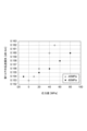
- Figure 6 is a graph showing the relationship between the ratio of the compressive stress cross-sectional area to the cross-sectional area of the fiber and the transmission loss.
- the transmission loss of the first core and the transmission loss of the second core showed roughly the same tendency, so here the first core is shown as a representative example.
- the ratio of the compressive stress cross-sectional area to the cross-sectional area of the fiber was in the range of approximately 15% to 25%, the transmission loss was particularly reduced.
- the ratio of the compressive stress cross-sectional area to the cross-sectional area of the fiber was smaller or larger than this range, the transmission loss tended to increase. The reasons for this are thought to be as follows.
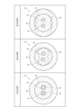
- Figure 7 is a cross-sectional view showing an example of stress distribution in an MCF.
- the area where compressive stress occurs is indicated by a two-dot chain line.
- Stress distribution 1 simulates a case where the ratio of compressive stress cross-sectional area to the cross-sectional area of the fiber is 15% or less.
- stress distribution 1 only the two cores 2 and their vicinity are under compressive stress, and there is an area between the two cores 2 where tensile stress occurs. In stress distribution 1, it is believed that the area between the cores 2 where tensile stress occurs causes an increase in transmission loss.
- Stress distribution 2 simulates a case where the ratio of compressive stress cross-sectional area to the cross-sectional area of the fiber is approximately 15% to 25%. In stress distribution 2, the areas of compressive stress centered on each core overlap each other between two cores, and there is no area of tensile stress between the two cores 2.
- Stress distribution 3 simulates a case where the ratio of compressive stress cross-sectional area to the fiber cross-sectional area is greater than 25%. In stress distribution 3, there are no areas of tensile stress between the cores 2, but areas of compressive stress exist in much of the second cladding 4. In stress distribution 3, the area of the areas of compressive stress is too large, making it impossible to impart sufficient compressive stress to the core 2, which is thought to result in increased transmission loss.
- two adjacent cores 2 among the multiple cores 2 may have different shapes.
- Two adjacent cores 2 may have different core diameters.
- Two adjacent cores 2 may have different refractive indices.
Landscapes
- Chemical & Material Sciences (AREA)
- Engineering & Computer Science (AREA)
- Physics & Mathematics (AREA)
- Geochemistry & Mineralogy (AREA)
- Life Sciences & Earth Sciences (AREA)
- General Chemical & Material Sciences (AREA)
- Materials Engineering (AREA)
- Organic Chemistry (AREA)
- Chemical Kinetics & Catalysis (AREA)
- General Life Sciences & Earth Sciences (AREA)
- Manufacturing & Machinery (AREA)
- Optics & Photonics (AREA)
- General Physics & Mathematics (AREA)
- Glass Compositions (AREA)
Priority Applications (3)
| Application Number | Priority Date | Filing Date | Title |
|---|---|---|---|
| JP2025506601A JPWO2024190234A1 (https=) | 2023-03-15 | 2024-02-13 | |
| CN202480017671.0A CN120858306A (zh) | 2023-03-15 | 2024-02-13 | 多芯光纤 |
| EP24770351.5A EP4682598A1 (en) | 2023-03-15 | 2024-02-13 | Multicore optical fiber |
Applications Claiming Priority (2)
| Application Number | Priority Date | Filing Date | Title |
|---|---|---|---|
| JP2023040847 | 2023-03-15 | ||
| JP2023-040847 | 2023-03-15 |
Publications (1)
| Publication Number | Publication Date |
|---|---|
| WO2024190234A1 true WO2024190234A1 (ja) | 2024-09-19 |
Family
ID=92755372
Family Applications (1)
| Application Number | Title | Priority Date | Filing Date |
|---|---|---|---|
| PCT/JP2024/004890 Ceased WO2024190234A1 (ja) | 2023-03-15 | 2024-02-13 | マルチコア光ファイバ |
Country Status (4)
| Country | Link |
|---|---|
| EP (1) | EP4682598A1 (https=) |
| JP (1) | JPWO2024190234A1 (https=) |
| CN (1) | CN120858306A (https=) |
| WO (1) | WO2024190234A1 (https=) |
Cited By (1)
| Publication number | Priority date | Publication date | Assignee | Title |
|---|---|---|---|---|
| WO2025070402A1 (ja) * | 2023-09-29 | 2025-04-03 | 古河電気工業株式会社 | マルチコアファイバ母材の製造方法およびマルチコアファイバの製造方法 |
Citations (7)
| Publication number | Priority date | Publication date | Assignee | Title |
|---|---|---|---|---|
| JP2017040878A (ja) | 2015-08-21 | 2017-02-23 | 株式会社フジクラ | マルチコアファイバ及び光ケーブル |
| JP2017075061A (ja) | 2015-10-13 | 2017-04-20 | 古河電気工業株式会社 | マルチコアファイバの製造方法 |
| JP2017161705A (ja) | 2016-03-09 | 2017-09-14 | 住友電気工業株式会社 | 結合型マルチコア光ファイバ |
| US20220043201A1 (en) * | 2020-08-10 | 2022-02-10 | Corning Incorporated | Ultra-low-loss coupled-core multicore optical fibers |
| WO2022059699A1 (ja) * | 2020-09-17 | 2022-03-24 | 古河電気工業株式会社 | マルチコアファイバ |
| WO2022085534A1 (ja) * | 2020-10-23 | 2022-04-28 | 住友電気工業株式会社 | マルチコア光ファイバ |
| JP2023040847A (ja) | 2021-09-10 | 2023-03-23 | ダイハツ工業株式会社 | 動力伝達装置 |
-
2024
- 2024-02-13 JP JP2025506601A patent/JPWO2024190234A1/ja active Pending
- 2024-02-13 CN CN202480017671.0A patent/CN120858306A/zh active Pending
- 2024-02-13 EP EP24770351.5A patent/EP4682598A1/en active Pending
- 2024-02-13 WO PCT/JP2024/004890 patent/WO2024190234A1/ja not_active Ceased
Patent Citations (7)
| Publication number | Priority date | Publication date | Assignee | Title |
|---|---|---|---|---|
| JP2017040878A (ja) | 2015-08-21 | 2017-02-23 | 株式会社フジクラ | マルチコアファイバ及び光ケーブル |
| JP2017075061A (ja) | 2015-10-13 | 2017-04-20 | 古河電気工業株式会社 | マルチコアファイバの製造方法 |
| JP2017161705A (ja) | 2016-03-09 | 2017-09-14 | 住友電気工業株式会社 | 結合型マルチコア光ファイバ |
| US20220043201A1 (en) * | 2020-08-10 | 2022-02-10 | Corning Incorporated | Ultra-low-loss coupled-core multicore optical fibers |
| WO2022059699A1 (ja) * | 2020-09-17 | 2022-03-24 | 古河電気工業株式会社 | マルチコアファイバ |
| WO2022085534A1 (ja) * | 2020-10-23 | 2022-04-28 | 住友電気工業株式会社 | マルチコア光ファイバ |
| JP2023040847A (ja) | 2021-09-10 | 2023-03-23 | ダイハツ工業株式会社 | 動力伝達装置 |
Non-Patent Citations (2)
| Title |
|---|
| M. KOSHIBAK. SAITOHY. KOKUBUN: "Heterogeneous multi-core fibers: proposal and design principle", IEICE ELECTRON. EXPRESS, vol. 6, no. 2, January 2009 (2009-01-01), pages 98 - 103 |
| See also references of EP4682598A1 |
Cited By (1)
| Publication number | Priority date | Publication date | Assignee | Title |
|---|---|---|---|---|
| WO2025070402A1 (ja) * | 2023-09-29 | 2025-04-03 | 古河電気工業株式会社 | マルチコアファイバ母材の製造方法およびマルチコアファイバの製造方法 |
Also Published As
| Publication number | Publication date |
|---|---|
| CN120858306A (zh) | 2025-10-28 |
| EP4682598A1 (en) | 2026-01-21 |
| JPWO2024190234A1 (https=) | 2024-09-19 |
Similar Documents
| Publication | Publication Date | Title |
|---|---|---|
| JP5881213B2 (ja) | シングルモード光ファイバ | |
| JP5636151B2 (ja) | 多波長、多モード光ファイバ | |
| JP6337509B2 (ja) | 光ファイバ母材製造方法 | |
| JP6298893B2 (ja) | 損失低下を示す、台形コアを有するシングルモードファイバ | |
| US10155687B2 (en) | Optical fiber preform | |
| JP7119531B2 (ja) | 光ファイバ | |
| JP6620633B2 (ja) | 光ファイバ | |
| WO2017145834A1 (ja) | 光ファイバ | |
| JP2021503630A (ja) | 2種類以上のハロゲンが共ドープされたコアを有する低損失の光ファイバ | |
| US11181684B2 (en) | Optical fiber | |
| WO2015079987A1 (ja) | 光ファイバ及び光ファイバ母材 | |
| WO2016017743A1 (ja) | 光ファイバ及びその製造方法 | |
| US10723650B2 (en) | Optical fiber preform | |
| WO2015200191A1 (en) | Low attenuation fiber with viscosity matched core and inner clad | |
| WO2024190234A1 (ja) | マルチコア光ファイバ | |
| JP7794128B2 (ja) | 光ファイバ母材の製造方法及び光ファイバ母材 | |
| JP2014214079A (ja) | 光ファイバ母材 | |
| JPWO2024190234A5 (https=) | ||
| JPS61191543A (ja) | 石英系光フアイバ | |
| WO2018138736A2 (en) | Optical fiber draw assembly and fabricated optical fiber thereof | |
| DK182061B1 (en) | Method for producing optical fiber base material, and optical fiber base material | |
| JP7677153B2 (ja) | 光ファイバ | |
| WO2024247623A1 (ja) | マルチコア光ファイバ | |
| WO2024048356A1 (ja) | 光ファイバ母材の製造方法及び光ファイバ母材 | |
| WO2025249168A1 (ja) | マルチコア光ファイバおよびマルチコア光ファイバ母材 |
Legal Events
| Date | Code | Title | Description |
|---|---|---|---|
| 121 | Ep: the epo has been informed by wipo that ep was designated in this application |
Ref document number: 24770351 Country of ref document: EP Kind code of ref document: A1 |
|
| ENP | Entry into the national phase |
Ref document number: 2025506601 Country of ref document: JP Kind code of ref document: A |
|
| WWE | Wipo information: entry into national phase |
Ref document number: 2025506601 Country of ref document: JP |
|
| WWE | Wipo information: entry into national phase |
Ref document number: 202480017671.0 Country of ref document: CN |
|
| WWE | Wipo information: entry into national phase |
Ref document number: 2024770351 Country of ref document: EP |
|
| NENP | Non-entry into the national phase |
Ref country code: DE |
|
| WWP | Wipo information: published in national office |
Ref document number: 202480017671.0 Country of ref document: CN |
|
| ENP | Entry into the national phase |
Ref document number: 2024770351 Country of ref document: EP Effective date: 20251015 |
|
| ENP | Entry into the national phase |
Ref document number: 2024770351 Country of ref document: EP Effective date: 20251015 |
|
| ENP | Entry into the national phase |
Ref document number: 2024770351 Country of ref document: EP Effective date: 20251015 |
|
| ENP | Entry into the national phase |
Ref document number: 2024770351 Country of ref document: EP Effective date: 20251015 |
|
| ENP | Entry into the national phase |
Ref document number: 2024770351 Country of ref document: EP Effective date: 20251015 |
|
| WWP | Wipo information: published in national office |
Ref document number: 2024770351 Country of ref document: EP |