WO2024190069A1 - プローブ - Google Patents
プローブ Download PDFInfo
- Publication number
- WO2024190069A1 WO2024190069A1 PCT/JP2024/001241 JP2024001241W WO2024190069A1 WO 2024190069 A1 WO2024190069 A1 WO 2024190069A1 JP 2024001241 W JP2024001241 W JP 2024001241W WO 2024190069 A1 WO2024190069 A1 WO 2024190069A1
- Authority
- WO
- WIPO (PCT)
- Prior art keywords
- plunger
- coil
- plane
- barrel
- coil portion
- Prior art date
- Legal status (The legal status is an assumption and is not a legal conclusion. Google has not performed a legal analysis and makes no representation as to the accuracy of the status listed.)
- Ceased
Links
Images



Classifications
-
- G—PHYSICS
- G01—MEASURING; TESTING
- G01R—MEASURING ELECTRIC VARIABLES; MEASURING MAGNETIC VARIABLES
- G01R1/00—Details of instruments or arrangements of the types included in groups G01R5/00 - G01R13/00 and G01R31/00
- G01R1/02—General constructional details
- G01R1/06—Measuring leads; Measuring probes
- G01R1/067—Measuring probes
- G01R1/06711—Probe needles; Cantilever beams; "Bump" contacts; Replaceable probe pins
- G01R1/06716—Elastic
- G01R1/06722—Spring-loaded
-
- G—PHYSICS
- G01—MEASURING; TESTING
- G01R—MEASURING ELECTRIC VARIABLES; MEASURING MAGNETIC VARIABLES
- G01R1/00—Details of instruments or arrangements of the types included in groups G01R5/00 - G01R13/00 and G01R31/00
- G01R1/02—General constructional details
- G01R1/06—Measuring leads; Measuring probes
- G01R1/067—Measuring probes
-
- G—PHYSICS
- G01—MEASURING; TESTING
- G01R—MEASURING ELECTRIC VARIABLES; MEASURING MAGNETIC VARIABLES
- G01R1/00—Details of instruments or arrangements of the types included in groups G01R5/00 - G01R13/00 and G01R31/00
- G01R1/02—General constructional details
- G01R1/06—Measuring leads; Measuring probes
- G01R1/067—Measuring probes
- G01R1/06711—Probe needles; Cantilever beams; "Bump" contacts; Replaceable probe pins
- G01R1/06733—Geometry aspects
-
- G—PHYSICS
- G01—MEASURING; TESTING
- G01R—MEASURING ELECTRIC VARIABLES; MEASURING MAGNETIC VARIABLES
- G01R31/00—Arrangements for testing electric properties; Arrangements for locating electric faults; Arrangements for electrical testing characterised by what is being tested not provided for elsewhere
- G01R31/26—Testing of individual semiconductor devices
-
- G—PHYSICS
- G01—MEASURING; TESTING
- G01R—MEASURING ELECTRIC VARIABLES; MEASURING MAGNETIC VARIABLES
- G01R31/00—Arrangements for testing electric properties; Arrangements for locating electric faults; Arrangements for electrical testing characterised by what is being tested not provided for elsewhere
- G01R31/28—Testing of electronic circuits, e.g. by signal tracer
- G01R31/2851—Testing of integrated circuits [IC]
- G01R31/2886—Features relating to contacting the IC under test, e.g. probe heads; chucks
- G01R31/2889—Interfaces, e.g. between probe and tester
Definitions
- the present invention relates to a probe.
- one object of the present invention is to stably press the plunger against the inner wall of the barrel.
- One aspect of the present invention is a probe comprising a first plunger, a barrel that holds the first plunger in a movable state, and a coil spring that biases the first plunger, the coil spring having a first coil portion, a second coil portion, and a third coil portion, the first coil portion being located at one end of the third coil portion and in contact with the first plunger, and the second coil portion being located at the other end of the third coil portion, and in a state where no load is applied to the coil spring, at least one of a first plane perpendicular to the first central axis of the first coil portion and a second plane perpendicular to the second central axis of the second coil portion is non-parallel to a third plane perpendicular to the third central axis of the third coil portion.
- the above aspect of the present invention allows the plunger to be stably pressed against the inner wall of the barrel.
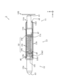
- FIG. 4 is a configuration diagram of the probe before a force is applied to a first plunger in the embodiment.
- FIG. FIG. 2 is an exploded view of the probe according to the embodiment.
- FIG. 2 is a side view of the coil spring of the present embodiment.
- 4 is a configuration diagram of the probe in the present embodiment in a state where a force is applied to a first plunger.
- the barrel 13 is shown in cross section, and the other members are shown in side view.
- the direction in which the plunger and barrel are aligned is defined as the x direction
- the direction perpendicular to the x direction is defined as the y direction.
- the direction in which the first plunger 11, barrel 13, and second plunger 12 are aligned is the x direction
- the radial direction of each of the first plunger 11, barrel 13, and second plunger 12 is the y direction.
- the directions indicated by the arrows on the x and y axes are defined as the leftward and upward directions, respectively.
- the probe 1 in this embodiment includes a first plunger (terminal on the substrate side of the inspection device) 11, a second plunger (terminal on the inspection target side) 12, a barrel 13, and a coil spring 14.
- the probe 1 is a measuring device used for semiconductor inspection (see FIGS. 1 and 2).
- the first plunger 11, the second plunger 12, the barrel 13, and the coil spring 14 are made of conductive materials.
- the probe 1 is configured such that the coil spring 14 in the barrel 13 biases the first plunger 11 in a direction to protrude from the barrel 13.
- the first plunger 11 has a first contact portion 11a and a first base end portion 11b.
- the radial size of the first contact portion 11a is smaller than the radial size of the first base end portion 11b.
- the end (first tip a1) of the first contact portion 11a protrudes from the inside to the outside of the barrel 13. That is, at least a part of the first contact portion 11a is exposed from the barrel 13.
- the first base end 11b is held by the barrel 13 in a state in which it can move in the x direction.
- the side of the first contact portion 11a that contacts the first base end 11b (the left side of the first contact portion 11a in the x direction) is located inside the barrel 13.
- the end (second tip a2) on the left side in the x direction of the first base end 11b is formed with a first protrusion 11c that protrudes to the side where the second plunger 12 is located (the left side in the x direction).
- the radial size of the first protrusion 11c is smaller than the radial size of the second tip a2.
- the second tip a2 has a flat shape in the radial direction.
- the first coil portion 14a of the coil spring 14 is inserted into the first protrusion 11c.
- the second plunger 12 has a second contact portion 12a and a second base end portion 12b.
- the radial size of the second contact portion 12a is smaller than the radial size of the second base end portion 12b.
- the end (third tip a3) of the second contact portion 12a protrudes from the inside to the outside of the barrel 13. That is, at least a part of the second contact portion 12a is exposed from the barrel 13.
- the second base end 12b is held by the barrel 13 in a state where it cannot move relative to the barrel 13.
- the end (fourth tip a4) on the right side in the x direction of the second base end 12b is formed with a second protrusion 12c that protrudes to the side where the first plunger 11 is located (right side in the x direction).
- the radial size of the second protrusion 12c is smaller than the radial size of the fourth tip a4.
- the fourth tip a4 is a flat shape in the radial direction.
- the second coil portion 14b of the coil spring 14 is inserted into the second protrusion 12c.
- the second base end 12b has a first recessed region 12b1 whose outer diameter is smaller than that of the adjacent region.
- the barrel 13 has a main body portion 13a having a cylindrical shape.
- the end (fifth tip a5) of the main body 13a that holds the first plunger 11 is bent toward the inside of the cylindrical shape, forming a narrowed region (first convex region 13a1) with a smaller inner diameter.
- the first convex region 13a1 prevents the first base end 11b of the first plunger 11 from slipping out to the right in the x direction.
- the first convex region 13a1 may be formed around the entire circumference of the fifth tip a5, or may be formed on only a part of the fifth tip a5.
- a narrowed area (second convex area 13a2) that protrudes toward the inside of the cylindrical shape and has a smaller inner diameter is formed.
- the first recessed area 12b1 of the second base end 12b of the second plunger 12 is hooked onto the second convex area 13a2, and the second plunger 12 is fixed to the barrel 13.
- the second convex area 13a2 may be formed around the entire circumference of the inner wall of the main body 13a, or may be formed on only a part of the inner wall of the main body 13a.
- the coil spring 14 is located in the barrel 13 and biases the first plunger 11 in the x-direction, causing the first contact portion 11a of the first plunger 11 to protrude from the inside to the outside of the barrel 13.
- the coil spring 14 has a first coil portion 14a, a second coil portion 14b, and a third coil portion 14c (see FIGS. 3 and 4).
- the first coil portion 14a, the second coil portion 14b, and the third coil portion 14c are integrally formed.
- the first coil portion 14a is located at one end of the third coil portion 14c and contacts the first plunger 11.
- the first coil portion 14a includes a seat winding and is configured with a closed end.
- the second coil portion 14b is located at the other end of the third coil portion 14c and contacts the second plunger 12.
- the second coil portion 14b includes a seat winding and is configured with a closed end.
- the inner diameters of the first coil portion 14a and the second coil portion 14b are smaller than the inner diameter of the third coil portion 14c.
- the third coil portion 14c is deflected more greatly in response to a load than the first coil portion 14a and the second coil portion 14b.
- the third coil portion 14c is formed of a generally cylindrical spring whose inner diameter at the end portion is smaller than the inner diameter at the center portion.
- the outer diameters of the first coil portion 14a, the second coil portion 14b, and the third coil portion 14c are smaller than the inner diameter of the barrel 13.
- the first plane E1 perpendicular to the central axis (first central axis LX1) of the first coil portion 14a forms a predetermined angle (first angle ⁇ 1) less than 90 degrees with the central axis (third central axis LX3) of the third coil portion 14c. That is, the first plane E1 is not parallel to the third plane E3 perpendicular to the third central axis LX3. In other words, the first plane E1 is inclined with respect to the third plane E3. Since the first plane E1 is inclined with respect to the third plane E3, the first central axis LX1 extends in a direction different from the direction in which the third central axis LX3 extends (x direction). In addition, the first central axis LX1 intersects with the end face of the first coil portion 14a at a position shifted from the area through which the third central axis LX3 passes on the end face of the first coil portion 14a.
- the second plane E2 perpendicular to the central axis (second central axis LX2) of the second coil portion 14b forms a predetermined angle (second angle ⁇ 2) less than 90 degrees with the third central axis LX3. That is, the second plane E2 is not parallel to the third plane E3 perpendicular to the third central axis LX3. In other words, the second plane E2 is inclined with respect to the third plane E3. Since the second plane E2 is inclined with respect to the third plane E3, the second central axis LX2 extends in a direction different from the direction in which the third central axis LX3 extends (x direction). In addition, the second central axis LX2 intersects with the end face of the second coil portion 14b at a position shifted from the area through which the third central axis LX3 passes on the end face of the second coil portion 14b.
- first angle ⁇ 1 and the second angle ⁇ 2 are the same angle between 75 degrees and 85 degrees.
- the winding pitch of the coil spring 14 is formed as follows:
- At least one of the pitch of the windings close to the first coil portion 14a of the third coil portion 14c (11th pitch P11) and the pitch between the third coil portion 14c and the first coil portion 14a (12th pitch P12) on one side in the y direction (e.g., the upper side in the y direction) is narrower than the pitch of the other region (the pitch of the region of the third coil portion 14c away from the first coil portion 14a and the second coil portion 14b (3rd pitch P3)).
- at least one of the 11th pitch P11 and the 12th pitch P12 on the other side in the y direction is wider than the third pitch P3.
- At least one of the pitch of the winding of the third coil portion 14c close to the second coil portion 14b (21st pitch P21) and the pitch between the third coil portion 14c and the second coil portion 14b (22nd pitch P22) on one side of the y direction is narrower than the third pitch P3. And/or at least one of the pitches of the 21st pitch P21 and the 22nd pitch P22 on the other side of the y direction is wider than the third pitch P3.
- the coil spring 14 is formed so that on one side of the y direction, the first plane E1 and the third plane E3 approach each other, and on the other side of the y direction, the first plane E1 and the third plane E3 move away from each other, and on one side of the y direction, the second plane E2 and the third plane E3 approach each other, and on the other side of the y direction, the second plane E2 and the third plane E3 move away from each other, i.e., the first plane E1 and the second plane E2 intersect to form an approximate V-shape.
- the coil spring 14 be formed so that the first plane E1 and the second plane E2 are in a line-symmetrical positional relationship, i.e., so that the first angle ⁇ 1 and the second angle ⁇ 2 are equal.
- first plane E1 and the second plane E2 are not parallel to the third plane E3
- other positional relationships are also possible, such as the first plane E1 and the second plane E2 being parallel.
- a second convex region 13a2 is formed by a punch or the like.
- the first recessed region 12b1 of the second base end 12b fits into the second convex region 13a2 of the body portion 13a of the barrel 13, and the second plunger 12 is fixed to the barrel 13.
- the probe 1 of this embodiment is formed.
- the force applied to the first plunger 11 and the second plunger 12 pushes the first plunger 11 into the barrel 13.
- a compressive force is applied to the coil spring 14.
- the third coil portion 14c contracts in the x direction and is partially displaced in the y direction, deforming into an arched or serpentine shape. Because the third coil portion 14c deforms into an arched or serpentine shape, a portion of the third coil portion 14c comes into contact with the inner wall of the barrel 13.
- the first coil portion 14a pushes the first plunger 11 in the x direction.
- the first coil portion 14a also pushes the first plunger 11 in the y direction, in the opposite direction to the displacement of the third coil portion 14c (applies lateral pressure).
- the first coil portion 14a pushes the first plunger 11 in the y direction, the first base end portion 11b is pressed against the inner wall of the barrel 13, causing the first plunger 11 to become tilted.
- the first plunger 11 is electrically connected to the second plunger 12 via the barrel 13.
- the first plunger 11 can be stably pressed against the inner wall of the barrel 13, making it easier to maintain the first plunger 11 electrically connected to the barrel 13. And it makes it easier to maintain the first plunger 11 electrically connected to the second plunger 12 via the barrel 13.
- the coil spring 14 can be deformed into an arched or serpentine shape, so that a portion of the coil spring 14 can easily come into contact with the inner wall of the barrel 13. Even if the second plane E2 is inclined with respect to the third plane E3, a portion of the coil spring 14 can be easily brought into contact with the inner wall of the barrel 13. Therefore, as long as at least one of the first plane E1 and the second plane E2 is inclined with respect to the third plane E3, the first plunger 11 can be pressed against the inner wall of the barrel 13 in a stable manner.
- the first plunger 11 can be pressed against the inner wall of the barrel 13 more stably in a configuration in which both the first plane E1 and the second plane E2 are inclined with respect to the third plane E3 than in a configuration in which only one of the first plane E1 and the second plane E2 is inclined with respect to the third plane E3.
- the coil spring 14 is easier to form than in a configuration in which the first plane E1 and the second plane E2 are not line-symmetrically positioned. Also, the coil spring 14 can be inserted into the barrel 13 without considering the insertion direction.
- the first protrusion 11c functions as a spring support for the coil spring 14 and restricts the first coil portion 14a of the coil spring 14 from being significantly displaced in the radial direction (such as the y direction). By restricting the first coil portion 14a from being significantly displaced in the radial direction, the coil spring 14 can reliably press the first plunger 11 against the inner wall of the barrel 13.
- the second plunger 12 In the present embodiment, an example has been described in which the second plunger 12 is fixed to the barrel 13. However, the second plunger 12 may be held in the barrel 13 in a state in which it is movable in the x direction. When the second plunger 12 is held in the barrel 13 in a state in which it is movable in the x direction, the coil spring 14 of the present embodiment can also stably press the second plunger 12 against the inner wall of the barrel 13.
- first coil portion 14a and the second coil portion 14b Application examples of the first coil portion 14a and the second coil portion 14b
- the first coil portion 14a and the second coil portion 14b include end turns and are configured with closed ends.
- at least one of the first coil portion 14a and the second coil portion 14b may be configured with an open end without including an end turn.
- Aspect 1 comprises a first plunger, a barrel that holds the first plunger in a movably state, and a coil spring that biases the first plunger, wherein the coil spring has a first coil portion, a second coil portion, and a third coil portion, wherein the first coil portion is located at one end of the third coil portion and is in contact with the first plunger, and the second coil portion is located at the other end of the third coil portion, and when no load is applied to the coil spring, at least one of a first plane perpendicular to a first central axis of the first coil portion and a second plane perpendicular to a second central axis of the second coil portion is non-parallel to a third plane perpendicular to a third central axis of the third coil portion.
- the coil spring when a compressive force is applied to the coil spring, the coil spring deforms into an arched or serpentine shape, and a portion of the coil spring is likely to come into contact with the inner wall of the barrel. Because a portion of the coil spring comes into contact with the inner wall of the barrel, the force with which the first coil portion presses the first plunger against the inner wall of the barrel increases, making it easier to maintain contact between the first plunger and the barrel. In other words, the first plunger can be stably pressed against the inner wall of the barrel, making it easier to maintain the first plunger electrically connected to the barrel.
- the coil spring is formed in a positional relationship in which the first plane and the second plane intersect with each other when no load is applied to the coil spring.
- the radial component of the biasing force of the coil spring is large, and compared to a configuration in which the first plane and the second plane do not intersect, the end face of the first coil portion can be pressed against the barrel of the first plunger more stably.
- the coil spring is formed in a positional relationship in which the first plane and the second plane are line-symmetrical when no load is applied to the coil spring.
- the above-mentioned embodiment makes it easier to form the coil spring compared to a configuration in which the coil spring is formed in a positional relationship in which the first plane and the second plane are not line-symmetrical.
- the coil spring can be inserted into the barrel without considering the insertion direction.
- the first plunger is formed with a protrusion into which the first coil portion is inserted.
- the protrusion functions as a spring support for the coil spring, restricting the first coil portion of the coil spring from being displaced significantly in the radial direction.
- the coil spring can reliably press the first plunger against the inner wall of the barrel.
Landscapes
- Physics & Mathematics (AREA)
- General Physics & Mathematics (AREA)
- Engineering & Computer Science (AREA)
- Computer Hardware Design (AREA)
- Microelectronics & Electronic Packaging (AREA)
- General Engineering & Computer Science (AREA)
- Geometry (AREA)
- Measuring Leads Or Probes (AREA)
- Testing Of Individual Semiconductor Devices (AREA)
Abstract
Description
本実施形態におけるプローブ1は、第1プランジャー(検査装置の基板側端子)11、第2プランジャー(検査対象物側端子)12、バレル13、コイルバネ14を備える。プローブ1は、半導体検査に用いられる計測機器である(図1、図2参照)。第1プランジャー11、第2プランジャー12、バレル13、コイルバネ14は、導電性の部材で構成される。プローブ1は、バレル13内のコイルバネ14で第1プランジャー11をバレル13から突出させる向きに付勢する構成である。
第1プランジャー11は、第1接触部11a、第1基端部11bを有する。第1接触部11aの径方向の大きさは、第1基端部11bの径方向の大きさよりも小さい。
第2プランジャー12は、第2接触部12a、第2基端部12bを有する。第2接触部12aの径方向の大きさは、第2基端部12bの径方向の大きさよりも小さい。
バレル13は、筒形状を有する本体部13aを有する。
コイルバネ14は、バレル13内に位置し、第1プランジャー11をx方向に付勢し、第1プランジャー11の第1接触部11aをバレル13の内側から外側に突出させる。コイルバネ14は、第1コイル部14a、第2コイル部14b、第3コイル部14cを有する(図3、図4参照)。第1コイル部14aと第2コイル部14bと第3コイル部14cは、一体的に構成される。第1コイル部14aは、第3コイル部14cの端部の一方に位置し、第1プランジャー11と接する。第1コイル部14aは、座巻を含み、クローズドエンドで構成される。第2コイル部14bは、第3コイル部14cの端部の他方に位置し、第2プランジャー12と接する。第2コイル部14bは、座巻を含み、クローズドエンドで構成される。第1コイル部14aと第2コイル部14bの内径は、第3コイル部14cの内径よりも小さい。第3コイル部14cは、第1コイル部14aと第2コイル部14bと比べて、荷重負荷に応じて大きく撓む。第3コイル部14cは、端部の内径が中心部の内径よりも細い略たる型形状のバネで構成される。第1コイル部14aと第2コイル部14bと第3コイル部14cの外径は、バレル13の内径よりも小さい。
第1プランジャー11の第1基端部11bの第2先端部a2が、バレル13の本体部13aの第1凸領域13a1がある側の端部(第5先端部a5)から挿入される。なお、この際にはバレル13には第1凸領域13a1と第2凸領域13a2は形成されていない。バレル13の本体部13aに第1基端部11bが完全に挿入されると、カシメ加工などにより、第1凸領域13a1が形成される。
第1プランジャー11がバレル13に取り付けられた後、コイルバネ14が、バレルの本体部における第2プランジャーを保持する側の端部(第6先端部a6)から挿入され、続いて、第2プランジャー12の第2基端部12bが、第6先端部a6から挿入される。第1プランジャー11の第1凸部11cには、コイルバネ14の第1コイル部14aが挿入され、第2プランジャー12の第2凸部12cには、コイルバネ14の第2コイル部14bが挿入される。
プローブ1が検査用ソケット(不図示)に取り付けられ、プローブ1の第1プランジャー11の第1接触部11aの第1先端部a1が検査装置の基板100に接触すると、プローブ1が検査対象物側に持ち上がる。その後、検査対象物側から第2プランジャー12に力が加えられる(図4参照)。
第1平面E1が第3平面E3に対して傾斜しているため、第1平面E1と第3平面E3とが平行である形態に比べて、コイルバネ14にx方向の圧縮力が加わった時に、コイルバネ14がアーチ形状若しくは蛇行形状に変形して一部がバレル13の内壁に接触しやすい。
コイルバネ14による付勢力の径方向成分が大きくなり、第1平面E1と第2平面E2とが交差しない形態と比べて、第1コイル部14aの端面が、第1プランジャー11のバレル13への押しつけを安定的に出来る。
第1平面E1と第2平面E2とが線対称でない位置関係でコイルバネ14が形成される形態に比べて、コイルバネ14を形成しやすい。また、挿入する向きを考慮せずに、コイルバネ14をバレル13に挿入出来る。
第1凸部11cが、コイルバネ14のバネ受けとして機能し、コイルバネ14の第1コイル部14aが径方向(y方向など)に大きくずれることを制限する。第1コイル部14aが径方向に大きくずれることが制限されることにより、コイルバネ14によって確実に第1プランジャー11をバレル13の内壁に押しつけることが可能になる。
本実施形態では、第2プランジャー12がバレル13に固定される例を説明した。しかしながら、第2プランジャー12がx方向に移動可能な状態で、バレル13に保持されてもよい。第2プランジャー12がx方向に移動可能な状態で、バレル13に保持されている場合、本実施形態のコイルバネ14によって、第2プランジャー12も安定的にバレル13の内壁に押しつけることが出来る。
本実施形態では、第1コイル部14aと第2コイル部14bが座巻を含み、クローズドエンドで構成される例を説明した。しかしながら、第1コイル部14aと第2コイル部14bの少なくとも一方が、座巻を含まずに、オープンエンドで構成されてもよい。
(態様1)
態様1は、第1プランジャーと、前記第1プランジャーを移動可能な状態で保持するバレルと、前記第1プランジャーを付勢するコイルバネと、を備え、前記コイルバネは、第1コイル部と、第2コイル部と、第3コイル部とを有し、前記第1コイル部は、前記第3コイル部の端部の一方に位置し、前記第1プランジャーと接し、前記第2コイル部は、前記第3コイル部の端部の他方に位置し、前記コイルバネに荷重負荷を与えない状態で、前記第1コイル部の第1中心軸に垂直な第1平面と、前記第2コイル部の第2中心軸に垂直な第2平面の少なくとも一方は、前記第3コイル部の第3中心軸と垂直な第3平面と非平行である。
態様2では、前記コイルバネに荷重負荷を与えない状態で、前記第1平面と前記第2平面とが、交差する位置関係で、前記コイルバネが形成される。
態様3では、前記コイルバネに荷重負荷を与えない状態で、前記第1平面と前記第2平面は線対称となる位置関係で、前記コイルバネが形成される。
態様4では、前記第1プランジャーには、前記第1コイル部が挿入される凸部が形成される。
Claims (4)
- 第1プランジャーと、
前記第1プランジャーを移動可能な状態で保持するバレルと、
前記第1プランジャーを付勢するコイルバネと、を備え、
前記コイルバネは、第1コイル部と、第2コイル部と、第3コイル部とを有し、
前記第1コイル部は、前記第3コイル部の端部の一方に位置し、前記第1プランジャーと接し、
前記第2コイル部は、前記第3コイル部の端部の他方に位置し、
前記コイルバネに荷重負荷を与えない状態で、前記第1コイル部の第1中心軸に垂直な第1平面と、前記第2コイル部の第2中心軸に垂直な第2平面の少なくとも一方は、前記第3コイル部の第3中心軸と垂直な第3平面と非平行である、プローブ。 - 前記コイルバネに荷重負荷を与えない状態で、前記第1平面と前記第2平面とが、交差する位置関係で、前記コイルバネが形成される、請求項1に記載のプローブ。
- 前記コイルバネに荷重負荷を与えない状態で、前記第1平面と前記第2平面は線対称となる位置関係で、前記コイルバネが形成される、請求項2に記載のプローブ。
- 前記第1プランジャーには、前記第1コイル部が挿入される凸部が形成される、請求項1~3のいずれか一項に記載のプローブ。
Priority Applications (2)
| Application Number | Priority Date | Filing Date | Title |
|---|---|---|---|
| KR1020257030369A KR20250162545A (ko) | 2023-03-13 | 2024-01-18 | 프로브 |
| CN202480018337.7A CN120898135A (zh) | 2023-03-13 | 2024-01-18 | 探针 |
Applications Claiming Priority (2)
| Application Number | Priority Date | Filing Date | Title |
|---|---|---|---|
| JP2023038240A JP2024129204A (ja) | 2023-03-13 | 2023-03-13 | プローブ |
| JP2023-038240 | 2023-03-13 |
Publications (1)
| Publication Number | Publication Date |
|---|---|
| WO2024190069A1 true WO2024190069A1 (ja) | 2024-09-19 |
Family
ID=92754713
Family Applications (1)
| Application Number | Title | Priority Date | Filing Date |
|---|---|---|---|
| PCT/JP2024/001241 Ceased WO2024190069A1 (ja) | 2023-03-13 | 2024-01-18 | プローブ |
Country Status (5)
| Country | Link |
|---|---|
| JP (1) | JP2024129204A (ja) |
| KR (1) | KR20250162545A (ja) |
| CN (1) | CN120898135A (ja) |
| TW (1) | TW202436879A (ja) |
| WO (1) | WO2024190069A1 (ja) |
Citations (5)
| Publication number | Priority date | Publication date | Assignee | Title |
|---|---|---|---|---|
| JP2001255340A (ja) * | 2000-03-13 | 2001-09-21 | Yokowo Co Ltd | コンタクトプローブ及び該コンタクトプローブを設けたicパッケージ検査用ソケット |
| JP2002008761A (ja) * | 2000-06-23 | 2002-01-11 | Tyco Electronics Amp Kk | スプリングコンタクト |
| WO2011058646A1 (ja) * | 2009-11-13 | 2011-05-19 | テスト ツーリング ソリューションズ グループ ピイ ティ イー リミテッド | プローブピン |
| JP2013224891A (ja) * | 2012-04-23 | 2013-10-31 | Denso Corp | 検査装置 |
| JP2016008904A (ja) * | 2014-06-25 | 2016-01-18 | 株式会社ミタカ | コンタクトプローブ |
Family Cites Families (1)
| Publication number | Priority date | Publication date | Assignee | Title |
|---|---|---|---|---|
| JP2020165803A (ja) | 2019-03-29 | 2020-10-08 | 山一電機株式会社 | コンタクトプローブ及びこれを備えた検査用ソケット |
-
2023
- 2023-03-13 JP JP2023038240A patent/JP2024129204A/ja active Pending
-
2024
- 2024-01-18 CN CN202480018337.7A patent/CN120898135A/zh active Pending
- 2024-01-18 KR KR1020257030369A patent/KR20250162545A/ko active Pending
- 2024-01-18 WO PCT/JP2024/001241 patent/WO2024190069A1/ja not_active Ceased
- 2024-03-12 TW TW113109041A patent/TW202436879A/zh unknown
Patent Citations (5)
| Publication number | Priority date | Publication date | Assignee | Title |
|---|---|---|---|---|
| JP2001255340A (ja) * | 2000-03-13 | 2001-09-21 | Yokowo Co Ltd | コンタクトプローブ及び該コンタクトプローブを設けたicパッケージ検査用ソケット |
| JP2002008761A (ja) * | 2000-06-23 | 2002-01-11 | Tyco Electronics Amp Kk | スプリングコンタクト |
| WO2011058646A1 (ja) * | 2009-11-13 | 2011-05-19 | テスト ツーリング ソリューションズ グループ ピイ ティ イー リミテッド | プローブピン |
| JP2013224891A (ja) * | 2012-04-23 | 2013-10-31 | Denso Corp | 検査装置 |
| JP2016008904A (ja) * | 2014-06-25 | 2016-01-18 | 株式会社ミタカ | コンタクトプローブ |
Also Published As
| Publication number | Publication date |
|---|---|
| KR20250162545A (ko) | 2025-11-18 |
| CN120898135A (zh) | 2025-11-04 |
| TW202436879A (zh) | 2024-09-16 |
| JP2024129204A (ja) | 2024-09-27 |
Similar Documents
| Publication | Publication Date | Title |
|---|---|---|
| KR101869335B1 (ko) | 프로브 핀 및 그 제조방법 | |
| JP4964754B2 (ja) | コンタクト部材 | |
| JP5858781B2 (ja) | プローブピン及び電気部品用ソケット | |
| JP6126082B2 (ja) | コネクタ | |
| US8710856B2 (en) | Terminal for flat test probe | |
| TW201730566A (zh) | 探針以及使用該探針的檢查裝置 | |
| JP4999079B2 (ja) | プローブ | |
| JP6553472B2 (ja) | コンタクタ | |
| WO2016092916A1 (ja) | プローブピン、および、これを備えた電子デバイス | |
| US9236199B2 (en) | Switch | |
| JP7686353B2 (ja) | コネクタ | |
| WO2024190069A1 (ja) | プローブ | |
| KR102304874B1 (ko) | 반도체 검사용 프로브 핀 | |
| WO2019131438A1 (ja) | プローブピン及びソケット | |
| JP2019153399A (ja) | 接続端子 | |
| US12596137B2 (en) | Pogo pin with adjustable elastic force | |
| JP5567523B2 (ja) | 接続ピン | |
| WO2023181906A1 (ja) | スプリングコネクタ | |
| JP2019216068A (ja) | コネクタ | |
| US20230178906A1 (en) | Spring connector | |
| US20230058577A1 (en) | Contact pin and socket | |
| WO2023228844A1 (ja) | プローブ | |
| JP7267799B2 (ja) | 音叉振動子を備える荷重センサ | |
| US20130035008A1 (en) | Terminal fitting | |
| JP4399348B2 (ja) | ソケットコネクタ |
Legal Events
| Date | Code | Title | Description |
|---|---|---|---|
| 121 | Ep: the epo has been informed by wipo that ep was designated in this application |
Ref document number: 24770191 Country of ref document: EP Kind code of ref document: A1 |
|
| ENP | Entry into the national phase |
Ref document number: 1020257030369 Country of ref document: KR Free format text: ST27 STATUS EVENT CODE: A-0-1-A10-A15-NAP-PA0105 (AS PROVIDED BY THE NATIONAL OFFICE) |
|
| WWE | Wipo information: entry into national phase |
Ref document number: 202480018337.7 Country of ref document: CN |
|
| NENP | Non-entry into the national phase |
Ref country code: DE |
|
| WWP | Wipo information: published in national office |
Ref document number: 202480018337.7 Country of ref document: CN |
|
| 122 | Ep: pct application non-entry in european phase |
Ref document number: 24770191 Country of ref document: EP Kind code of ref document: A1 |