WO2024190068A1 - 推定装置、推定方法、及び記録媒体 - Google Patents
推定装置、推定方法、及び記録媒体 Download PDFInfo
- Publication number
- WO2024190068A1 WO2024190068A1 PCT/JP2024/001231 JP2024001231W WO2024190068A1 WO 2024190068 A1 WO2024190068 A1 WO 2024190068A1 JP 2024001231 W JP2024001231 W JP 2024001231W WO 2024190068 A1 WO2024190068 A1 WO 2024190068A1
- Authority
- WO
- WIPO (PCT)
- Prior art keywords
- person
- tracked
- target time
- camera
- time
- Prior art date
- Legal status (The legal status is an assumption and is not a legal conclusion. Google has not performed a legal analysis and makes no representation as to the accuracy of the status listed.)
- Ceased
Links
Images




Classifications
-
- G—PHYSICS
- G06—COMPUTING OR CALCULATING; COUNTING
- G06Q—INFORMATION AND COMMUNICATION TECHNOLOGY [ICT] SPECIALLY ADAPTED FOR ADMINISTRATIVE, COMMERCIAL, FINANCIAL, MANAGERIAL OR SUPERVISORY PURPOSES; SYSTEMS OR METHODS SPECIALLY ADAPTED FOR ADMINISTRATIVE, COMMERCIAL, FINANCIAL, MANAGERIAL OR SUPERVISORY PURPOSES, NOT OTHERWISE PROVIDED FOR
- G06Q50/00—Information and communication technology [ICT] specially adapted for implementation of business processes of specific business sectors, e.g. utilities or tourism
- G06Q50/10—Services
Definitions
- the present invention relates to an estimation device, an estimation method, and a program.
- Patent Document 1 Technology related to the present invention is disclosed in Patent Document 1.
- the technology disclosed in Patent Document 1 discloses a technology for tracking a target person based on images generated by multiple cameras.
- one example of the objective of the present invention is to provide an estimation device, an estimation method, and a program for estimating the area in which a tracked person is present at a target time.
- a person detection means for detecting a person to be tracked from images generated by a plurality of cameras installed at predetermined positions; a camera identification means for identifying the camera in which the timing at which the person to be tracked is detected in an image satisfies a predetermined condition based on a target time; an estimation means for estimating an area in which the person to be tracked is present at the target time based on the identified installation position of the camera;
- An estimator is provided having the following:
- One or more computers Detects a person to be tracked from images generated by multiple cameras installed at specified locations, Identifying the camera in which the timing at which the person to be tracked is detected in the image satisfies a predetermined condition based on a target time; An estimation method is provided for estimating an area in which the tracked person is present at the target time based on the identified installation position of the camera.
- a person detection means for detecting a person to be tracked from images generated by a plurality of cameras installed at predetermined positions; a camera identification means for identifying the camera in which the timing at which the person to be tracked is detected in an image satisfies a predetermined condition based on a target time; an estimation means for estimating an area in which the person to be tracked is present at the target time based on the identified installation position of the camera;
- a program is provided to function as a
- an estimation device, estimation method, and program are realized that estimate the area in which a tracked person is present at a target time.
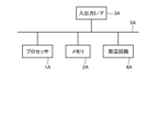
- FIG. 2 is a diagram illustrating an example of a functional block diagram of an estimation device.
- FIG. 2 is a diagram illustrating an example of a hardware configuration of an estimation device.
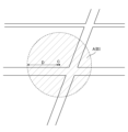
- FIG. 11 is a diagram for explaining an example of a process in which the estimation device estimates a predetermined area.
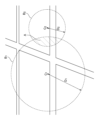
- 11 is a diagram for explaining another example of a process in which the estimation device estimates a predetermined area.
- FIG. 11 is a diagram for explaining another example of a process in which the estimation device estimates a predetermined area.
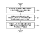
- FIG. 13 is a flowchart showing an example of a process flow of the estimation device.
- 11 is a diagram illustrating an example of a process in which the estimation device estimates a visit target of a tracked person.
- FIG. 13 is a flowchart showing an example of a process flow of the estimation device.
- FIG. 4 is a diagram illustrating an example of information output by the estimation device.
- First Embodiment 1 is a functional block diagram showing an overview of an estimation device 10 according to a first embodiment.
- the estimation device 10 includes a human detection unit 11, a camera identification unit 12, and an estimation unit 13.
- the person detection unit 11 detects the person to be tracked from images generated by multiple cameras installed at specified positions.
- the camera identification unit 12 identifies the camera from which the timing at which the person to be tracked is detected in the image satisfies specified conditions based on the target time.
- the estimation unit 13 estimates the area in which the person to be tracked is present at the target time based on the installation positions of the identified cameras.
- the estimation device 10 of this embodiment identifies a camera whose timing at which the tracked person was detected in the image satisfies a predetermined condition based on the target time, and estimates the area in which the tracked person is located at the target time based on the installation position of the identified camera.
- the estimation device 10 of this embodiment can estimate with high accuracy the area in which the tracked person is located at the target time.
- the estimation device 10 of the second embodiment is a specific embodiment of the estimation device 10 of the first embodiment. That is, the estimation device 10 identifies a camera whose timing of detecting a tracking target person in an image satisfies a predetermined condition based on a target time, and estimates an area in which the tracking target person exists at the target time based on the installation position of the identified camera. This will be described in detail below.
- the hardware configuration of the estimation device 10 is realized by any combination of hardware and software.
- the software includes programs that are stored in advance when the device is shipped, and programs downloaded from recording media such as CDs (Compact Discs) or servers on the Internet.
- FIG. 2 is a block diagram illustrating an example of the hardware configuration of the estimation device 10.
- the estimation device 10 has a processor 1A, a memory 2A, an input/output interface 3A, a peripheral circuit 4A, and a bus 5A.
- the peripheral circuit 4A includes various modules.
- the estimation device 10 does not have to have the peripheral circuit 4A.
- the estimation device 10 may be composed of multiple devices that are physically and/or logically separated. In this case, each of the multiple devices can have the above hardware configuration.
- the bus 5A is a data transmission path for the processor 1A, memory 2A, peripheral circuit 4A, and input/output interface 3A to send and receive data to each other.
- the processor 1A is an arithmetic processing device such as a CPU or a GPU (Graphics Processing Unit).
- the memory 2A is a memory such as a RAM (Random Access Memory) or a ROM (Read Only Memory).
- the input/output interface 3A includes interfaces for acquiring information from an input device, an external device, an external server, an external sensor, a camera, etc., and interfaces for outputting information to an output device, an external device, an external server, etc.
- the input/output interface 3A also includes an interface for connecting to a communication network such as the Internet.
- Examples of input devices include a keyboard, a mouse, a microphone, a physical button, a touch panel, etc.
- Examples of output devices include a display, a speaker, a printer, a mailer, etc.
- the processor 1A can issue commands to each module and perform calculations based on the results of those calculations.
- Fig. 1 shows an example of a functional block diagram of the estimation device 10 of this embodiment.
- the estimation device 10 of this embodiment has a person detection unit 11, a camera identification unit 12, and an estimation unit 13.
- the person detection unit 11 detects people to be tracked from images generated by multiple cameras installed at specified positions.
- Image is a concept that includes moving images.
- the "camera” captures images.
- the camera may be a surveillance camera.
- the camera is installed at a predetermined location and captures the surrounding area of that location. There are no particular limitations on where the camera is installed.
- the camera may be installed on the street or inside a facility. Examples of facilities include, but are not limited to, department stores, museums, and art galleries.
- the camera may be installed outdoors or indoors.
- Information indicating the installation location of each of the multiple cameras is registered in advance in the estimation device 10.
- the installation location of the camera may be indicated by latitude and longitude, or may be indicated by address.
- the installation location of the camera may be indicated by location information specific to the facility, such as an aisle number or room number.
- the images generated by each of the multiple cameras are input to the estimation device 10 by any means.
- the estimation device 10 and the cameras may be connected so as to be able to communicate with each other.
- the cameras may then transmit the images they generate to the estimation device 10.
- the images generated by the cameras may be stored in any storage means.
- the images stored in the storage means may then be input to the estimation device 10 by manual operation by a user.
- the input of images to the estimation device 10 may be performed by real-time processing or by batch processing.
- the human detection unit 11 can acquire the images input to the estimation device 10 in this manner. Note that the human detection unit 11 may acquire images by other means.
- “Acquisition” includes at least one of the following: the device goes to retrieve data or information stored in another device or storage medium (active acquisition), and the device inputs data or information output from another device (passive acquisition). Examples of active acquisition include making a request or inquiry to another device and receiving a reply, and accessing and reading information from another device or storage medium. An example of passive acquisition is receiving information that is distributed (or transmitted, push notification, etc.). Furthermore, “acquisition” may mean selecting and acquiring data or information from received data or information, or selecting and receiving distributed data or information.
- the person detection unit 11 detects the person to be tracked from the image acquired in this manner.
- the person detection unit 11 detects the person to be tracked from the image based on information indicating the features of the appearance of the person to be tracked.
- the "information indicating the external appearance features of the tracked person" is input to the estimation device 10 by the user.
- the user may input the external appearance features of the tracked person to the estimation device 10.
- the user may input an image of the tracked person to the estimation device 10.
- the person detection unit 11 may then analyze the image and extract the external appearance features of the tracked person.
- the "appearance features of the person being tracked” include, but are not limited to, facial features, body features, clothing features, possessions features, shoe features, etc.
- the person detection unit 11 detects the person to be tracked from among images from multiple cameras based on the external appearance features of the person to be tracked.
- the person detection unit 11 can then record the detection results in a detection history.
- the detection history indicates the timing at which the person to be tracked was detected for each camera.
- the timing at which the person to be tracked was detected is the shooting date and time of the frame image in which the person to be tracked was detected.
- the person detection unit 11 can identify the shooting date and time of the frame image in which the person to be tracked was detected based on the timestamp assigned to the image.
- the camera identification unit 12 identifies cameras whose timing at which a person to be tracked was detected in an image satisfies a predetermined condition.
- the predetermined condition is defined based on the target time.
- the camera identification unit 12 can identify cameras that satisfy the predetermined condition, for example, based on the detection history described above.
- the "target time” is the timing at which the area in which the tracked person is located is estimated. That is, the estimation device 10 estimates the area in which the tracked person is located at the target time.
- the target time is the current time, or a current, future, or past time specified by the user. For example, the current time may be automatically set as the target time. Alternatively, the target time may be set by user input. The user can set any current, future, or past time as the target time.
- the “predetermined conditions” may include at least one of the following conditions 1 to 4.
- condition 1 is a predetermined condition
- the camera identification unit 12 identifies, from among multiple cameras, the camera that detected the person to be tracked at the timing closest to the target time.
- the detection timing may be either earlier or later than the target time.
- condition 2 is a predetermined condition
- the camera identification unit 12 identifies, from among the multiple cameras, a camera in which the person to be tracked was detected before the target time and at a timing closest to the target time.
- condition 3 is a predetermined condition
- the camera identification unit 12 identifies from among the multiple cameras a camera in which the person to be tracked was detected after the target time and at a timing closest to the target time.
- condition 4 is a specified condition
- the camera identification unit 12 identifies, from among multiple cameras, a camera in which the person to be tracked was detected within a reference time from the target time. The detection timing may be before or after the target time. If condition 4 is a specified condition, the number of cameras identified by the camera identification unit 12 varies.
- the predetermined condition may be a combination of multiple conditions 1 to 4 above connected by AND or OR conditions.
- condition 1 and condition 4 may be the specified conditions.
- the camera identification unit 12 identifies, from among multiple cameras, a camera in which the person to be tracked was detected within a reference time from the target time and at a timing closest to the target time.
- the detection timing may be either earlier or later than the target time.
- condition 2 and condition 4 may be set as the predetermined conditions.
- the camera identification unit 12 identifies, from among the multiple cameras, a camera in which the person to be tracked was detected within a reference time from the target time, and which detected the person to be tracked at a timing that was closest to the target time and before the target time.
- Condition 3 and Condition 4 may be set as the predetermined conditions.
- the camera identification unit 12 identifies, from among the multiple cameras, a camera in which the person to be tracked is detected within a reference time from the target time, and which detects the person to be tracked after the target time and at a timing closest to the target time.
- condition 2 or condition 3 may be the specified condition.
- the camera identification unit 12 identifies, from among the multiple cameras, both a camera in which the person to be tracked was detected before the target time and at a timing closest to the target time, and a camera in which the person to be tracked was detected after the target time and at a timing closest to the target time.
- This condition 2 or condition 3 may be combined with condition 4 using an AND condition.
- the specified condition that combines condition 2 or condition 3, or condition 2 or condition 3 with condition 4 using an AND condition may be used, for example, when the target time is a time in the past.
- the estimation unit 13 estimates the area in which the person to be tracked is present at the target time based on the installation position of the camera identified by the camera identification unit 12.
- the estimation unit 13 can execute at least one of the following area estimation processes 1 to 3.
- the area estimation process 1 is suitable for use in a case where one camera is identified by the camera identification unit 12 .
- the estimation unit 13 calculates the travel time, which is the time difference between the target time and the most recent detection timing at which the person to be tracked was detected in an image generated by the camera identified by the camera identification unit 12.
- the “most recent detection timing” is the timing closest to the target time among the timings at which the person to be tracked was detected in the image generated by the camera identified by the camera identification unit 12. If a camera is identified as satisfying the above condition 2, the most recent detection timing is the timing before the target time among the timings at which the person to be tracked was detected in the image generated by that camera and closest to the target time. If a camera is identified as satisfying the above condition 3, the most recent detection timing is the timing after the target time among the timings at which the person to be tracked was detected in the image generated by that camera and closest to the target time.
- the estimation unit 13 also determines an estimated movement speed of the person being tracked.
- the estimation unit 13 determines the estimated movement speed based on the characteristics of the person being tracked acquired through user input or analysis of the image generated by the camera.
- the characteristics of the person being tracked include at least one of the following: the age of the person being tracked, sex, whether or not they are carrying luggage, the size of the luggage, whether or not they are injured, the means of transportation (walking, bicycle, motorcycle, car, etc.), and the movement speed in the image.
- the estimation unit 13 can calculate the estimated movement speed of the person to be tracked based on, for example, this person characteristic information.
- a speed calculation model is generated in advance, which takes these person characteristic information as input and outputs the estimated movement speed calculated based on the input person characteristic information.
- the speed calculation model may be a function, a learning model generated by machine learning, or something else.
- the estimation unit 13 inputs the person characteristic information of the person to be tracked into such a speed calculation model, and obtains the estimated movement speed output from the speed calculation model.
- the estimation unit 13 may calculate the movement speed of the person to be tracked in the image based on the image, and the calculation result may be used as the estimated movement speed of the person to be tracked. Calculation of the movement speed of the person detected in the image can be realized using any technology.
- the estimation unit 13 calculates the estimated travel distance of the person to be tracked between the most recent detection timing and the target time based on the travel time and the estimated travel speed.
- the estimated travel distance can be calculated simply as the product of the travel time and the estimated travel speed, but other methods may also be used.
- the estimation unit 13 estimates area B within an estimated movement distance D from the installation position of camera C identified by the camera identification unit 12 as area A in which the person to be tracked is present at the target time.
- the area estimation process 2 is suitable for use in the case where two or more cameras are identified by the camera identification unit 12. For example, when the predetermined condition is condition 2 or condition 3, two cameras may be identified. Also, when the predetermined condition is condition 4, two or more cameras may be identified.
- the estimation unit 13 calculates the travel time for each identified camera using a process similar to that described in area estimation process 1.
- the estimation unit 13 also calculates an estimated travel speed as a common value that is applied to all cameras using a process similar to that described in area estimation process 1.
- the estimation unit 13 then calculates an estimated travel distance for each identified camera using a process similar to that described in area estimation process 1.
- the estimation unit 13 specifies an area within an estimated movement distance from the installation position of each camera specified by the camera specification unit 12.
- FIG. 4 shows an example in which two cameras C 1 and C 2 are specified by the camera specification unit 12. An area B 1 within an estimated movement distance D 1 from the installation position of the camera C 1 and an area B 2 within an estimated movement distance D 2 from the installation position of the camera C 2 are shown.
- the estimation unit 13 estimates an overlapping area between the area B 1 and the area B 2 as an area A in which a person to be tracked exists at a target time.
- M cameras M is an integer of 2 or more
- the estimation unit 13 can estimate an area in which all M areas B 1 to B m overlap as an area A in which a person to be tracked exists at a target time.
- the estimation unit 13 determines whether or not the following three conditions, which will be described with reference to FIG.
- the target time is the current time.
- a camera C1 identified by the camera identification unit 12 is installed on one road. After the most recent detection timing at which the tracked person was detected in the image generated by the camera C 1 , the tracked person was not detected in the image generated by the other camera C 2.
- the other camera C 2 is a camera installed ahead of the direction of movement of the tracked person on a single road (the direction indicated by the arrow in the figure) identified based on the image generated by the camera C 1 .
- the estimation unit 13 estimates the area between the imaging area E1 of the camera C1 identified by the camera identification unit 12 and the imaging area E2 of the other camera C2 as the area in which the person to be tracked is present at the target time.
- a “single road” is a road with no branches.
- a single road may be a road, or a corridor or passageway within a facility. Map information or a floor map of a facility in which single roads are identifiable is registered in advance in the estimation device 10.
- the estimation unit 13 can determine whether each road is a single road or not based on the information.
- the "direction of movement of the tracked person on a single road” can be determined using any technology based on the direction of movement of the tracked person within the image, etc.
- the "other camera C 2 installed ahead in the movement direction" can be specified based on information indicating the installation position of the camera registered in advance, the above-mentioned map information, a floor map of the facility, or the like.
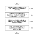
- the estimation device 10 executes a process to detect the person to be tracked from images generated by multiple cameras installed at predetermined positions (S10).
- the estimation device 10 identifies a camera whose timing at which the person to be tracked is detected in the image satisfies a predetermined condition based on the target time (S11).
- the estimation device 10 estimates the area in which the person to be tracked is present at the target time based on the installation positions of the cameras identified in S11 (S12). Note that if no camera is identified in S11, the estimation device 10 can end the process without executing S12.
- the estimation device 10 can output the estimation result.
- the estimation device 10 can output the estimation result via an output device such as a display or a projection device.
- the estimation device 10 may output information indicating an area A on a map (or a floor map of a facility) in which it is estimated that the person to be tracked is present at the target time, as the estimation result.
- the estimation device 10 may output information indicating the installation position of the camera identified by the camera identification unit 12, the most recent detection timing, etc., as auxiliary information to the estimation result.
- the estimation device 10 may output the estimated movement speed and estimated movement distance as auxiliary information to the estimation result.
- the estimation device 10 of this embodiment identifies a camera that detected the person to be tracked at a timing close to the target time, and estimates the area in which the person to be tracked exists at the target time based on the installation position of the camera and the estimated moving speed of the person to be tracked. With such an estimation device 10, even if the person to be tracked does not appear in the image captured at the target time, it is possible to estimate the area in which the person to be tracked exists at the target time. In this embodiment, even if the shooting areas of multiple cameras do not overlap with each other and there are areas that are not captured by any of the cameras, it is possible to estimate the area in which the person to be tracked exists at the target time.
- the estimation device 10 of this embodiment includes a means for estimating objects visited by the tracked person in facilities that exist within an area in which the tracked person is estimated to exist, as will be described in detail below.
- the estimation unit 13 estimates the area in which the tracked person is present at the target time using the method described in the first and second embodiments. The estimation unit 13 then estimates the facilities that the tracked person will visit within the estimated area based on at least one of the tracked person's clothing, belongings, age, sex, accompanying person, means of transportation, travel route, and target time. Note that the number of facilities estimated to be visited may be one or multiple.
- the clothing, belongings, age, gender, companions, means of transportation, and route traveled by the tracked person are determined through user input or analysis of camera-generated images.
- “Clothing” refers to the type of clothing. For example, athletic wear, fashionable clothes, casual clothes, suits, etc. There are various means for identifying the type of clothing through image analysis. For example, the above classification can be made based on the brand, design, shape characteristics, etc. of the clothing. For example, the classification can be realized using a classifier generated by machine learning, or other means can be adopted.
- Belongings refers to the type of belongings. For example, sports equipment, a business bag, a shopping bag, etc. There are various means for identifying the type of belongings using image analysis. For example, the above classification can be performed based on the characteristics of their appearance. For example, the classification can be achieved using a classifier generated by machine learning, or other means can be adopted.
- “Means of transportation” include walking, bicycle, motorbike, car, etc.
- the "movement route” is determined based on the detection results from multiple cameras.
- the estimation unit 13 can execute at least one of the following facility estimation processes 1 to 4.
- the estimation unit 13 identifies facilities that exist within the estimated area based on map information, a floor map of the facility, and the like that are registered in advance in the estimation device 10.
- Examples of facilities whose positions are indicated by map information, a floor map of the facility, and the like include parks, supermarkets, department stores, hospitals, and the like.
- Examples of facilities provided within the facility include kids' corners, nursing rooms, diaper changing stations, exercise facilities, and the like. Note that the examples given here are merely examples and are not limited to these.
- the characteristic information for each of the multiple facilities is registered in advance in the estimation device 10.
- the facility characteristic information indicates the purpose of each facility, the characteristics of the people who use each facility, and the usage time of each facility.
- the purpose of each facility is exercise, shopping, play, etc.
- the characteristics of the people who use each facility are indicated by clothing, belongings, age, gender, means of transportation, etc.
- the estimation unit 13 can, for example, estimate the purpose of the tracked person from the clothing and belongings of the tracked person, and estimate facilities that match that purpose as the tracked person's intended visit destination. For example, information that associates the type of clothing and belongings with the purpose may be registered in advance in the estimation device 10. The estimation unit 13 may then estimate the purpose of the tracked person based on that information.
- the estimation unit 13 can estimate that a facility is visited by a tracked person if the similarity between the characteristics of a person using the facility and the characteristics of the tracked person is equal to or greater than a reference value.
- the similarity of characteristics can be calculated using any technique. For example, the similarity may be calculated based on the number of items whose values match. In this case, the greater the number of items whose values match, the higher the similarity.
- the characteristics of the person using the facility and the characteristics of the person being tracked are as explained in Facility Estimation Process 1.
- the items are items included in the characteristics of a person, such as clothing, belongings, age, gender, and means of transportation.
- the characteristics of the person using the facility can be linked to each item and set to multiple values.
- a facility used by both men and women can be linked to gender and set to both male and female.
- “the characteristics of the person using the facility and the characteristics of the person being tracked match" means that the characteristics of the person being tracked are included in the characteristics of the person using the facility.
- the estimation unit 13 can estimate the visit destinations of the person to be tracked based on the movement route.
- FIG. 7 shows the movement route R of the tracked person, an area A where the tracked person is estimated to be present at the target time, and a plurality of facilities F1 to F3 present in area A. If the tracked person is visiting facility F1 or facility F3 , the tracked person will reach these facilities by taking a detour. On the other hand, if the tracked person is visiting facility F2 , the tracked person will reach the facility via the shortest route.
- the estimation unit 13 estimates facility F2 as a destination of the person to be tracked.
- the estimation unit 13 identifies a facility that will be reached via the shortest route based on the movement route of the person to be tracked and the positional relationship between each of the multiple facilities. Then, the estimation unit 13 estimates the identified facility as a destination of the person to be tracked.
- the shortest route can be determined by a route search with an arbitrary position on the movement route R of the person to be tracked as the starting point and each facility as the destination. Then, if the route is the same as the shortest route calculated by the route search or the deviation from the shortest route calculated by the route search is within a reference value, it may be determined to be the shortest route, and if these conditions are not met, it may be determined to be a longer route.
- the starting point may be changed to another position on the movement route R and the above process may be performed multiple times.
- a facility that is determined to be the shortest route in either case, or that is determined to be the shortest route a predetermined number of times or more may be presumed to be a destination visited by the person to be tracked.
- the deviation from the shortest route calculated by route search is indicated by the difference in distance between the first route and the second route, or the difference in the time required for travel. The greater the difference, the greater the deviation from the shortest route.
- the first route is the "shortest route calculated by route search.”
- the second route is "a route that has the same starting point and destination as the first route, moves to the end point indicated by the movement route R of the tracked person, and then moves from there to the destination via the shortest route calculated by route search.”
- the estimation unit 13 can exclude facilities whose target time is not within the usage hours from the visit destinations of the tracked person. For example, the estimation unit 13 may estimate the remaining facilities that have not been excluded as the visit destinations of the tracked person. In addition, the estimation unit 13 may estimate the visit destinations of the tracked person from the remaining facilities that have not been excluded using any of the facility estimation processes 1 to 3 described above.
- the estimation device 10 executes a process to detect the tracked person from images generated by multiple cameras installed at predetermined positions (S20). Next, the estimation device 10 identifies a camera whose timing at which the tracked person was detected in the image satisfies a predetermined condition based on the target time (S21). Next, the estimation device 10 estimates the area in which the tracked person is present at the target time based on the installation positions of the cameras identified in S21 (S22). Thereafter, the estimation device 10 estimates the visit destinations of the tracked person among facilities present in the area estimated in S22 (S23). Note that if no cameras are identified in S21, the estimation device 10 can end the process without executing S22 and S23.
- the estimation device 10 can output the estimation result.
- the estimation device 10 can output the estimation result via an output device such as a display or a projection device.
- the estimation device 10 may output information indicating an area A on a map (or on a floor map of a facility) in which it is estimated that the person to be tracked is present at the target time as the estimation result.
- the estimation device 10 may also highlight a facility estimated to be visited by the person to be tracked on the map (or on a floor map of the facility).
- the estimation device 10 may also output information indicating the installation position of the camera identified by the camera identification unit 12, the most recent detection timing, etc., as auxiliary information of the estimation result.
- the estimation device 10 may output the estimated movement speed and estimated movement distance as auxiliary information of the estimation result.
- the rest of the configuration of the estimation device 10 is the same as in the first and second embodiments.
- the estimation device 10 of this embodiment achieves the same effects as the estimation device 10 of the first and second embodiments.
- the estimation device 10 of this embodiment can estimate the destinations (facilities) visited by the tracked person based on at least one of the tracked person's clothing, belongings, age, sex, accompanying person, vehicle, travel route, and target time.
- the estimation device 10 can output information indicating the imaging areas E2 and E3 of the predetermined cameras C2 and C3 that exist in the area A in which it is estimated that the person to be tracked exists at the target time.
- the predetermined cameras C2 and C3 are cameras that have not been specified by the camera specification unit 12. That is, the predetermined cameras C2 and C3 are cameras that do not satisfy the predetermined conditions detailed in the second embodiment.
- the imaging areas E2 and E3 of such predetermined cameras C2 and C3 can be removed from candidates for the area in which the person to be tracked exists at the target time. The user can grasp the area in which the person to be tracked exists at the target time based on the information as shown in FIG. 9.
- a person detection means for detecting a person to be tracked from images generated by a plurality of cameras installed at predetermined positions; a camera identification means for identifying the camera in which the timing at which the person to be tracked is detected in an image satisfies a predetermined condition based on a target time; an estimation means for estimating an area in which the person to be tracked is present at the target time based on the identified installation position of the camera; An estimation device having the following: 2.
- the predetermined condition is: The person to be tracked was detected at the timing closest to the target time among the plurality of cameras.
- the person to be tracked was detected among the plurality of cameras at a timing closest to the target time, before the target time.
- the person to be tracked is detected after the target time among the plurality of cameras at a timing closest to the target time; and
- the person to be tracked was detected within a reference time from the target time.
- the estimation device according to claim 1 comprising at least one of the following: 3.
- the target time is: 3.
- the estimation device according to claim 1 or 2 wherein the time is the current time, or a current, future or past time specified by the user. 4.
- the estimation means calculating an estimated movement distance of the tracked person between the most recent detection time and the target time based on a time difference between the most recent detection time at which the tracked person was detected in the image generated by the identified camera and the target time, and an estimated movement speed of the tracked person; 4.
- the estimation device according to any one of 1 to 3, which estimates an area within the estimated movement distance from the identified installation position of the camera as an area in which the tracked person is present at the target time. 5.
- the estimation means 5 5.
- the estimation device which estimates, as the area in which the tracked person is present at the target time, an overlapping area of an area within the estimated moving distance from the installation position of the camera where the tracked person was detected before the target time and closest to the target time, and an area within the estimated moving distance from the installation position of the camera where the tracked person was detected after the target time and closest to the target time. 6.
- the estimation means 6 The estimation device according to claim 4 or 5, wherein the estimated moving speed is determined based on user input or on characteristics of the tracked person obtained by analysis of images generated by the camera. 7.
- the estimation device wherein the characteristics of the tracked person include at least one of the tracked person's age, sex, whether or not the person is carrying luggage, the size of the luggage, whether or not the person is injured, the means of transportation, and the moving speed in the image.
- the estimation means the target time is the current time, The identified camera is installed on a single road, and after the tracking target person is detected in the image generated by the identified camera, the tracking target person is not detected in the image generated by another camera installed ahead of the tracking target person identified based on the image generated by the identified camera in the moving direction of the tracking target person,
- the estimation device according to any one of 1 to 7, which estimates an area between the identified camera and the other cameras as an area in which the tracked person is present at the target time.
- the estimation means 9.
- An estimation device which estimates visit destinations of the tracked person among facilities located in an area where the tracked person is estimated to be present at the target time based on at least one of the tracked person's clothing, belongings, age, gender, accompanying persons, means of transportation, travel route, and the target time.
- One or more computers Detects a person to be tracked from images generated by multiple cameras installed at specified locations, Identifying the camera in which the timing at which the person to be tracked is detected in the image satisfies a predetermined condition based on a target time; An estimation method for estimating an area in which the tracked person is present at the target time based on the identified installation position of the camera. 11.
- the computer A person detection means for detecting a person to be tracked from images generated by a plurality of cameras installed at predetermined positions; a camera identification means for identifying the camera in which the timing at which the person to be tracked is detected in an image satisfies a predetermined condition based on a target time; an estimation means for estimating an area in which the person to be tracked is present at the target time based on the identified installation position of the camera; A program that functions as a
Landscapes
- Business, Economics & Management (AREA)
- Tourism & Hospitality (AREA)
- Health & Medical Sciences (AREA)
- Economics (AREA)
- General Health & Medical Sciences (AREA)
- Human Resources & Organizations (AREA)
- Marketing (AREA)
- Primary Health Care (AREA)
- Strategic Management (AREA)
- Physics & Mathematics (AREA)
- General Business, Economics & Management (AREA)
- General Physics & Mathematics (AREA)
- Engineering & Computer Science (AREA)
- Theoretical Computer Science (AREA)
- Image Analysis (AREA)
Abstract
Description
所定位置に設置された複数のカメラが生成した画像の中から追跡対象の人物を検出する人物検出手段と、
画像の中で前記追跡対象の人物が検出されたタイミングが対象時刻に基づく所定条件を満たす前記カメラを特定するカメラ特定手段と、
特定された前記カメラの設置位置に基づき、前記対象時刻において前記追跡対象の人物が存在するエリアを推定する推定手段と、
を有する推定装置が提供される。
1つ以上のコンピュータが、
所定位置に設置された複数のカメラが生成した画像の中から追跡対象の人物を検出し、
画像の中で前記追跡対象の人物が検出されたタイミングが対象時刻に基づく所定条件を満たす前記カメラを特定し、
特定された前記カメラの設置位置に基づき、前記対象時刻において前記追跡対象の人物が存在するエリアを推定する推定方法が提供される。
コンピュータを、
所定位置に設置された複数のカメラが生成した画像の中から追跡対象の人物を検出する人物検出手段、
画像の中で前記追跡対象の人物が検出されたタイミングが対象時刻に基づく所定条件を満たす前記カメラを特定するカメラ特定手段、
特定された前記カメラの設置位置に基づき、前記対象時刻において前記追跡対象の人物が存在するエリアを推定する推定手段、
として機能させるプログラムが提供される。
図1は、第1の実施形態に係る推定装置10の概要を示す機能ブロック図である。推定装置10は、人物検出部11と、カメラ特定部12と、推定部13とを有する。
「概要」
第2の実施形態の推定装置10は、第1の実施形態の推定装置10を具体化したものである。すなわち、推定装置10は、画像の中で追跡対象の人物が検出されたタイミングが対象時刻に基づく所定条件を満たすカメラを特定し、特定されたカメラの設置位置に基づき、対象時刻において追跡対象の人物が存在するエリアを推定する。以下、詳細に説明する。
推定装置10のハードウエア構成の一例を説明する。推定装置10の各機能部は、ハードウエアとソフトウエアの任意の組み合わせによって実現される。その実現方法、装置にはいろいろな変形例があることは、当業者には理解されるところである。ソフトウエアは、予め装置を出荷する段階から格納されているプログラムや、CD(Compact Disc)等の記録媒体やインターネット上のサーバ等からダウンロードされたプログラム等を含む。
次に、本実施形態の推定装置10の機能構成を詳細に説明する。図1に、本実施形態の推定装置10の機能ブロック図の一例を示す。図示するように、本実施形態の推定装置10は、人物検出部11と、カメラ特定部12と、推定部13とを有する。
(条件2)対象時刻よりも前に、複数のカメラの中で一番対象時刻に近いタイミングで追跡対象の人物が検出された。
(条件3)対象時刻よりも後に、複数のカメラの中で一番対象時刻に近いタイミングで追跡対象の人物が検出された。
(条件4)対象時刻から基準時間以内に追跡対象の人物が検出された。
エリア推定処理1は、カメラ特定部12により1つのカメラが特定された場合の利用に好適である。
エリア推定処理2は、カメラ特定部12により2つ以上のカメラが特定された場合の利用に好適である。例えば、所定条件が条件2又は条件3である場合、2つのカメラが特定され得る。また、所定条件が条件4である場合、2つ以上のカメラが特定され得る。
エリア推定処理3では、推定部13は、図5を用いて説明する以下の3つの条件を満たすか否かを判断する。
・図5に示すように、カメラ特定部12により特定されたカメラC1が1本道に設置されている。
・カメラC1が生成した画像において追跡対象の人物が検出された上記直近検出タイミングよりも後に、他のカメラC2が生成した画像において追跡対象の人物が検出されていない。なお、他のカメラC2は、カメラC1が生成した画像に基づき特定した追跡対象の人物の1本道での移動方向(図中、矢印で示す方向)の先に設置されたカメラである。
本実施形態の推定装置10は、追跡対象の人物を対象時刻に近いタイミングで検出したカメラを特定し、そのカメラの設置位置と追跡対象の人物の推定移動速度とに基づき、対象時刻において追跡対象の人物が存在するエリアを推定する。このような推定装置10によれば、対象時刻に撮影された画像に追跡対象の人物が写っていなくても、対象時刻において追跡対象の人物が存在するエリアを推定することができる。本実施形態の場合、複数のカメラの撮影エリアが互いに重なっておらず、いずれのカメラにも撮影されていない箇所が存在しても、対象時刻において追跡対象の人物が存在するエリアを推定することができる。
本実施形態の推定装置10は、追跡対象の人物が存在すると推定したエリア内に存在する施設の中の追跡対象の人物の訪問対象を推定する手段を有する。以下、詳細に説明する。
まず、推定部13は、予め推定装置10に登録されている地図情報や施設のフロアマップ等に基づき、推定したエリア内に存在する施設を特定する。地図情報や施設のフロアマップ等で位置が示される施設としては、公園、スーパーマーケット、デパート、病院等が例示される。また、施設内に設けられた施設として、キッズコーナー、授乳室、おむつ交換所、運動施設等が例示される。なお、ここでの例示はあくまで一例であり、これらに限定されない。
推定部13は、例えば、施設を利用する人物の特性と追跡対象の人物の特性との類似度が基準値以上である施設を、追跡対象の人物の訪問対象と推定することができる。特性の類似度は、あらゆる技術を用いて算出することができる。例えば、値が一致する項目の数に基づき類似度を算出してもよい。この場合、値が一致する項目の数が多いほど類似度は高くなる。
推定部13は、移動ルートに基づき、追跡対象の人物の訪問対象を推定することができる。
推定部13は、対象時刻が利用時間内でない施設を、追跡対象の人物の訪問対象から除外することができる。例えば、推定部13は、除外されずに残った施設を、追跡対象の人物の訪問対象と推定してもよい。その他、推定部13は、除外されずに残った施設の中から、上述した施設推定処理1乃至3のいずれかを用いて、追跡対象の人物の訪問対象を推定してもよい。
推定装置10は、図9に示すように、対象時刻において追跡対象の人物が存在すると推定されたエリアAの中に存在する所定のカメラC2及びC3の撮像エリアE2及びE3を示した情報を出力することができる。所定のカメラC2及びC3は、カメラ特定部12により特定されていないカメラである。すなわち、所定のカメラC2及びC3は、第2の実施形態で詳述した所定条件を満たさないカメラである。このような所定のカメラC2及びC3の撮像エリアE2及びE3は、対象時刻において追跡対象の人物が存在するエリアの候補から外すことができる。ユーザは、図9に示すような情報に基づき、対象時刻において追跡対象の人物が存在するエリアを把握することができる。
1. 所定位置に設置された複数のカメラが生成した画像の中から追跡対象の人物を検出する人物検出手段と、
画像の中で前記追跡対象の人物が検出されたタイミングが対象時刻に基づく所定条件を満たす前記カメラを特定するカメラ特定手段と、
特定された前記カメラの設置位置に基づき、前記対象時刻において前記追跡対象の人物が存在するエリアを推定する推定手段と、
を有する推定装置。
2. 前記所定条件は、
複数の前記カメラの中で一番前記対象時刻に近いタイミングで、前記追跡対象の人物が検出された、
前記対象時刻よりも前に、複数の前記カメラの中で一番前記対象時刻に近いタイミングで前記追跡対象の人物が検出された、
前記対象時刻よりも後に、複数の前記カメラの中で一番前記対象時刻に近いタイミングで前記追跡対象の人物が検出された、及び、
前記対象時刻から基準時間以内に前記追跡対象の人物が検出された、
の中の少なくとも1つを含む1に記載の推定装置。
3. 前記対象時刻は、
現在の時刻、又はユーザが指定した現在、未来又は過去の時刻である1又は2に記載の推定装置。
4. 前記推定手段は、
特定された前記カメラが生成した画像の中で前記追跡対象の人物が検出された直近検出タイミングと前記対象時刻との時間差、及び前記追跡対象の人物の推定移動速度に基づき前記直近検出タイミングと前記対象時刻との間における前記追跡対象の人物の推定移動距離を算出し、
特定された前記カメラの設置位置から前記推定移動距離以内のエリアを、前記対象時刻において前記追跡対象の人物が存在するエリアとして推定する1から3のいずれかに記載の推定装置。
5. 前記推定手段は、
前記対象時刻よりも前に、前記対象時刻に最も近いタイミングで前記追跡対象の人物が検出された前記カメラの設置位置から前記推定移動距離以内のエリア、及び前記対象時刻よりも後に、前記対象時刻に最も近いタイミングで前記追跡対象の人物が検出された前記カメラの設置位置から前記推定移動距離以内のエリアの重なり合うエリアを、前記対象時刻において前記追跡対象の人物が存在するエリアとして推定する4に記載の推定装置。
6. 前記推定手段は、
ユーザ入力又は前記カメラが生成した画像の解析で取得した前記追跡対象の人物の特性に基づき、前記推定移動速度を決定する4又は5に記載の推定装置。
7. 前記追跡対象の人物の特性は、追跡対象の人物の年齢、性別、荷物の有無、荷物の大きさ、ケガの有無、移動手段、及び画像の中での移動速度の中の少なくとも1つを含む6に記載の推定装置。
8. 前記推定手段は、
前記対象時刻が現在の時刻であり、
特定された前記カメラが1本道に設置されており、かつ
特定された前記カメラが生成した画像において前記追跡対象の人物が検出された後に、特定された前記カメラが生成した画像に基づき特定した前記追跡対象の人物の移動方向の先に設置された他の前記カメラが生成した画像において前記追跡対象の人物が検出されていない場合、
特定された前記カメラと他の前記カメラとの間のエリアを、前記対象時刻において前記追跡対象の人物が存在するエリアとして推定する1から7のいずれかに記載の推定装置。
9. 前記推定手段は、
前記追跡対象の人物の衣服、持ち物、年齢、性別、同伴者、移動手段、移動ルート、及び前記対象時刻の中の少なくとも1つに基づき、前記対象時刻において前記追跡対象の人物が存在すると推定したエリア内に存在する施設の中の前記追跡対象の人物の訪問対象を推定する1から8のいずれかに記載の推定装置。
10. 1つ以上のコンピュータが、
所定位置に設置された複数のカメラが生成した画像の中から追跡対象の人物を検出し、
画像の中で前記追跡対象の人物が検出されたタイミングが対象時刻に基づく所定条件を満たす前記カメラを特定し、
特定された前記カメラの設置位置に基づき、前記対象時刻において前記追跡対象の人物が存在するエリアを推定する推定方法。
11. コンピュータを、
所定位置に設置された複数のカメラが生成した画像の中から追跡対象の人物を検出する人物検出手段、
画像の中で前記追跡対象の人物が検出されたタイミングが対象時刻に基づく所定条件を満たす前記カメラを特定するカメラ特定手段、
特定された前記カメラの設置位置に基づき、前記対象時刻において前記追跡対象の人物が存在するエリアを推定する推定手段、
として機能させるプログラム。
11 人物検出部
12 カメラ特定部
13 推定部
1A プロセッサ
2A メモリ
3A 入出力I/F
4A 周辺回路
5A バス
Claims (20)
- 所定位置に設置された複数のカメラが生成した画像の中から追跡対象の人物を検出する人物検出手段と、
画像の中で前記追跡対象の人物が検出されたタイミングが対象時刻に基づく所定条件を満たす前記カメラを特定するカメラ特定手段と、
特定された前記カメラの設置位置に基づき、前記対象時刻において前記追跡対象の人物が存在するエリアを推定する推定手段と、
を有する推定装置。 - 前記所定条件は、
複数の前記カメラの中で一番前記対象時刻に近いタイミングで、前記追跡対象の人物が検出された、
前記対象時刻よりも前に、複数の前記カメラの中で一番前記対象時刻に近いタイミングで前記追跡対象の人物が検出された、
前記対象時刻よりも後に、複数の前記カメラの中で一番前記対象時刻に近いタイミングで前記追跡対象の人物が検出された、及び、
前記対象時刻から基準時間以内に前記追跡対象の人物が検出された、
の中の少なくとも1つを含む請求項1に記載の推定装置。 - 前記対象時刻は、
現在の時刻、又はユーザが指定した現在、未来又は過去の時刻である請求項1又は2に記載の推定装置。 - 前記推定手段は、
特定された前記カメラが生成した画像の中で前記追跡対象の人物が検出された直近検出タイミングと前記対象時刻との時間差、及び前記追跡対象の人物の推定移動速度に基づき前記直近検出タイミングと前記対象時刻との間における前記追跡対象の人物の推定移動距離を算出し、
特定された前記カメラの設置位置から前記推定移動距離以内のエリアを、前記対象時刻において前記追跡対象の人物が存在するエリアとして推定する請求項1から3のいずれか1項に記載の推定装置。 - 前記推定手段は、
前記対象時刻よりも前に、前記対象時刻に最も近いタイミングで前記追跡対象の人物が検出された前記カメラの設置位置から前記推定移動距離以内のエリア、及び前記対象時刻よりも後に、前記対象時刻に最も近いタイミングで前記追跡対象の人物が検出された前記カメラの設置位置から前記推定移動距離以内のエリアの重なり合うエリアを、前記対象時刻において前記追跡対象の人物が存在するエリアとして推定する請求項4に記載の推定装置。 - 前記推定手段は、
ユーザ入力又は前記カメラが生成した画像の解析で取得した前記追跡対象の人物の特性に基づき、前記推定移動速度を決定する請求項4又は5に記載の推定装置。 - 前記追跡対象の人物の特性は、追跡対象の人物の年齢、性別、荷物の有無、荷物の大きさ、ケガの有無、移動手段、及び画像の中での移動速度の中の少なくとも1つを含む請求項6に記載の推定装置。
- 前記推定手段は、
前記対象時刻が現在の時刻であり、
特定された前記カメラが1本道に設置されており、かつ
特定された前記カメラが生成した画像において前記追跡対象の人物が検出された後に、特定された前記カメラが生成した画像に基づき特定した前記追跡対象の人物の移動方向の先に設置された他の前記カメラが生成した画像において前記追跡対象の人物が検出されていない場合、
特定された前記カメラと他の前記カメラとの間のエリアを、前記対象時刻において前記追跡対象の人物が存在するエリアとして推定する請求項1から7のいずれか1項に記載の推定装置。 - 前記推定手段は、
前記追跡対象の人物の衣服、持ち物、年齢、性別、同伴者、移動手段、移動ルート、及び前記対象時刻の中の少なくとも1つに基づき、前記対象時刻において前記追跡対象の人物が存在すると推定したエリア内に存在する施設の中の前記追跡対象の人物の訪問対象を推定する請求項1から8のいずれか1項に記載の推定装置。 - 1つ以上のコンピュータが、
所定位置に設置された複数のカメラが生成した画像の中から追跡対象の人物を検出し、
画像の中で前記追跡対象の人物が検出されたタイミングが対象時刻に基づく所定条件を満たす前記カメラを特定し、
特定された前記カメラの設置位置に基づき、前記対象時刻において前記追跡対象の人物が存在するエリアを推定する推定方法。 - 前記所定条件は、
複数の前記カメラの中で一番前記対象時刻に近いタイミングで、前記追跡対象の人物が検出された、
前記対象時刻よりも前に、複数の前記カメラの中で一番前記対象時刻に近いタイミングで前記追跡対象の人物が検出された、
前記対象時刻よりも後に、複数の前記カメラの中で一番前記対象時刻に近いタイミングで前記追跡対象の人物が検出された、及び、
前記対象時刻から基準時間以内に前記追跡対象の人物が検出された、
の中の少なくとも1つを含む請求項10に記載の推定方法。 - 前記対象時刻は、
現在の時刻、又はユーザが指定した現在、未来又は過去の時刻である請求項10又は11に記載の推定方法。 - 前記1つ以上のコンピュータが、
特定された前記カメラが生成した画像の中で前記追跡対象の人物が検出された直近検出タイミングと前記対象時刻との時間差、及び前記追跡対象の人物の推定移動速度に基づき前記直近検出タイミングと前記対象時刻との間における前記追跡対象の人物の推定移動距離を算出し、
特定された前記カメラの設置位置から前記推定移動距離以内のエリアを、前記対象時刻において前記追跡対象の人物が存在するエリアとして推定する請求項10から12のいずれか1項に記載の推定方法。 - 前記1つ以上のコンピュータが、
前記対象時刻よりも前に、前記対象時刻に最も近いタイミングで前記追跡対象の人物が検出された前記カメラの設置位置から前記推定移動距離以内のエリア、及び前記対象時刻よりも後に、前記対象時刻に最も近いタイミングで前記追跡対象の人物が検出された前記カメラの設置位置から前記推定移動距離以内のエリアの重なり合うエリアを、前記対象時刻において前記追跡対象の人物が存在するエリアとして推定する請求項13に記載の推定方法。 - 前記1つ以上のコンピュータが、
ユーザ入力又は前記カメラが生成した画像の解析で取得した前記追跡対象の人物の特性に基づき、前記推定移動速度を決定する請求項13又は14に記載の推定方法。 - コンピュータを、
所定位置に設置された複数のカメラが生成した画像の中から追跡対象の人物を検出する人物検出手段、
画像の中で前記追跡対象の人物が検出されたタイミングが対象時刻に基づく所定条件を満たす前記カメラを特定するカメラ特定手段、
特定された前記カメラの設置位置に基づき、前記対象時刻において前記追跡対象の人物が存在するエリアを推定する推定手段、
として機能させるプログラムを記録する記録媒体。 - 前記所定条件は、
複数の前記カメラの中で一番前記対象時刻に近いタイミングで、前記追跡対象の人物が検出された、
前記対象時刻よりも前に、複数の前記カメラの中で一番前記対象時刻に近いタイミングで前記追跡対象の人物が検出された、
前記対象時刻よりも後に、複数の前記カメラの中で一番前記対象時刻に近いタイミングで前記追跡対象の人物が検出された、及び、
前記対象時刻から基準時間以内に前記追跡対象の人物が検出された、
の中の少なくとも1つを含む請求項16に記載の記録媒体。 - 前記対象時刻は、
現在の時刻、又はユーザが指定した現在、未来又は過去の時刻である請求項16又は17に記載の記録媒体。 - 前記推定手段は、
特定された前記カメラが生成した画像の中で前記追跡対象の人物が検出された直近検出タイミングと前記対象時刻との時間差、及び前記追跡対象の人物の推定移動速度に基づき前記直近検出タイミングと前記対象時刻との間における前記追跡対象の人物の推定移動距離を算出し、
特定された前記カメラの設置位置から前記推定移動距離以内のエリアを、前記対象時刻において前記追跡対象の人物が存在するエリアとして推定する請求項16から18のいずれか1項に記載の記録媒体。 - 前記推定手段は、
前記対象時刻よりも前に、前記対象時刻に最も近いタイミングで前記追跡対象の人物が検出された前記カメラの設置位置から前記推定移動距離以内のエリア、及び前記対象時刻よりも後に、前記対象時刻に最も近いタイミングで前記追跡対象の人物が検出された前記カメラの設置位置から前記推定移動距離以内のエリアの重なり合うエリアを、前記対象時刻において前記追跡対象の人物が存在するエリアとして推定する請求項19に記載の記録媒体。
Priority Applications (1)
| Application Number | Priority Date | Filing Date | Title |
|---|---|---|---|
| JP2025506512A JPWO2024190068A5 (ja) | 2024-01-18 | 推定装置、推定方法、及びプログラム |
Applications Claiming Priority (2)
| Application Number | Priority Date | Filing Date | Title |
|---|---|---|---|
| JP2023041791 | 2023-03-16 | ||
| JP2023-041791 | 2023-03-16 |
Publications (1)
| Publication Number | Publication Date |
|---|---|
| WO2024190068A1 true WO2024190068A1 (ja) | 2024-09-19 |
Family
ID=92754794
Family Applications (1)
| Application Number | Title | Priority Date | Filing Date |
|---|---|---|---|
| PCT/JP2024/001231 Ceased WO2024190068A1 (ja) | 2023-03-16 | 2024-01-18 | 推定装置、推定方法、及び記録媒体 |
Country Status (1)
| Country | Link |
|---|---|
| WO (1) | WO2024190068A1 (ja) |
Citations (2)
| Publication number | Priority date | Publication date | Assignee | Title |
|---|---|---|---|---|
| JP2018179919A (ja) * | 2017-04-20 | 2018-11-15 | ラピスセミコンダクタ株式会社 | 位置推定方法、位置推定装置、および位置推定システム |
| JP2019009529A (ja) * | 2017-06-21 | 2019-01-17 | 日本電気株式会社 | 顔認証装置、人物追跡システム、人物追跡方法、および、人物追跡プログラム |
-
2024
- 2024-01-18 WO PCT/JP2024/001231 patent/WO2024190068A1/ja not_active Ceased
Patent Citations (2)
| Publication number | Priority date | Publication date | Assignee | Title |
|---|---|---|---|---|
| JP2018179919A (ja) * | 2017-04-20 | 2018-11-15 | ラピスセミコンダクタ株式会社 | 位置推定方法、位置推定装置、および位置推定システム |
| JP2019009529A (ja) * | 2017-06-21 | 2019-01-17 | 日本電気株式会社 | 顔認証装置、人物追跡システム、人物追跡方法、および、人物追跡プログラム |
Non-Patent Citations (1)
| Title |
|---|
| SAKAGUCHI SHOKI, AMAGASAKI MOTOKI, KIYAMA MASATO, OKAMOTO TOSHIAKI: "F-014: A study on person identification using multiple surveillance cameras", THE 21TH FORUM ON INFORMATION TECHNOLOGY, IEICE, vol. 2, 30 August 2022 (2022-08-30), pages 373 - 376, XP093210355 * |
Also Published As
| Publication number | Publication date |
|---|---|
| JPWO2024190068A1 (ja) | 2024-09-19 |
Similar Documents
| Publication | Publication Date | Title |
|---|---|---|
| US9934447B2 (en) | Object detection and classification | |
| US9922271B2 (en) | Object detection and classification | |
| JP6821762B2 (ja) | 畳み込みニューラルネットワークを利用してpoi変化を検出するためのシステムおよび方法 | |
| US20220067689A1 (en) | Automated shopping experience using cashier-less systems | |
| US10963893B1 (en) | Personalized decision tree based on in-store behavior analysis | |
| JP7771747B2 (ja) | 情報処理プログラム、情報処理方法および情報処理装置 | |
| Aljuaid et al. | Postures anomaly tracking and prediction learning model over crowd data analytics | |
| Islam et al. | An intelligent shopping support robot: understanding shopping behavior from 2D skeleton data using GRU network | |
| Lee et al. | Automatic physical activity and in‐vehicle status classification based on GPS and accelerometer data: A hierarchical classification approach using machine learning techniques | |
| Bae et al. | Fast and scalable structure-from-motion based localization for high-precision mobile augmented reality systems | |
| Quach et al. | Depth perspective-aware multiple object tracking | |
| EP3850590A1 (en) | Augmented reality mapping systems and related methods | |
| EP4207101B1 (en) | Information processing program, information processing method, and information processing apparatus | |
| JP7800134B2 (ja) | 情報処理プログラム、情報処理方法および情報処理装置 | |
| Mukherjee et al. | Ros-based pedestrian detection and distance estimation algorithm using stereo vision, leddar and cnn | |
| Dong et al. | Fast segmentation-based object tracking model for autonomous vehicles | |
| WO2024190068A1 (ja) | 推定装置、推定方法、及び記録媒体 | |
| JP2020160883A (ja) | 処理装置、処理方法及びプログラム | |
| JP2019174910A (ja) | 情報取得装置及び情報集計システム並びに情報集計装置 | |
| US20230206641A1 (en) | Storage medium, information processing method, and information processing apparatus | |
| Hu et al. | ALPS: Accurate landmark positioning at city scales | |
| JP2020173848A (ja) | 処理装置、処理方法及びプログラム | |
| US20240256892A1 (en) | Method and system for federated learning training for a neural network associated with autonomous vehicles | |
| JP7715583B2 (ja) | 位置特定支援システム、及び位置特定支援方法 | |
| Huang et al. | Landmark detection based on human activity recognition for automatic floor plan construction |
Legal Events
| Date | Code | Title | Description |
|---|---|---|---|
| 121 | Ep: the epo has been informed by wipo that ep was designated in this application |
Ref document number: 24770190 Country of ref document: EP Kind code of ref document: A1 |
|
| ENP | Entry into the national phase |
Ref document number: 2025506512 Country of ref document: JP Kind code of ref document: A |
|
| WWE | Wipo information: entry into national phase |
Ref document number: 2025506512 Country of ref document: JP |
|
| NENP | Non-entry into the national phase |
Ref country code: DE |
|
| 122 | Ep: pct application non-entry in european phase |
Ref document number: 24770190 Country of ref document: EP Kind code of ref document: A1 |