WO2024190067A1 - 追跡装置、追跡方法、及び記録媒体 - Google Patents
追跡装置、追跡方法、及び記録媒体 Download PDFInfo
- Publication number
- WO2024190067A1 WO2024190067A1 PCT/JP2024/001230 JP2024001230W WO2024190067A1 WO 2024190067 A1 WO2024190067 A1 WO 2024190067A1 JP 2024001230 W JP2024001230 W JP 2024001230W WO 2024190067 A1 WO2024190067 A1 WO 2024190067A1
- Authority
- WO
- WIPO (PCT)
- Prior art keywords
- person
- tracked
- tracking
- lost
- moving
- Prior art date
- Legal status (The legal status is an assumption and is not a legal conclusion. Google has not performed a legal analysis and makes no representation as to the accuracy of the status listed.)
- Ceased
Links
Images






Classifications
-
- G—PHYSICS
- G06—COMPUTING OR CALCULATING; COUNTING
- G06Q—INFORMATION AND COMMUNICATION TECHNOLOGY [ICT] SPECIALLY ADAPTED FOR ADMINISTRATIVE, COMMERCIAL, FINANCIAL, MANAGERIAL OR SUPERVISORY PURPOSES; SYSTEMS OR METHODS SPECIALLY ADAPTED FOR ADMINISTRATIVE, COMMERCIAL, FINANCIAL, MANAGERIAL OR SUPERVISORY PURPOSES, NOT OTHERWISE PROVIDED FOR
- G06Q50/00—Information and communication technology [ICT] specially adapted for implementation of business processes of specific business sectors, e.g. utilities or tourism
- G06Q50/10—Services
Definitions
- the present invention relates to a tracking device, a tracking method, and a program.
- Patent Document 1 while tracking a person using image analysis, begins tracking the vehicle when it detects that the person being tracked and the vehicle satisfy a specified condition.
- the specified condition is that the person has entered the vehicle or gotten on top of the vehicle.
- Patent Document 2 detects a person being tracked by analyzing images taken by a camera at the elevator's stop floor when the technology detects that the person being tracked has entered an elevator while tracking the person using image analysis. This technology detects that the person being tracked has entered an elevator based on the direction of movement of the person being tracked, etc.
- the inventors have discovered the following problem with technology that starts tracking a moving object when a person being tracked starts to move using the moving object.
- an image shows a scene in which a person being tracked gets on a moving body
- it is possible to identify the moving body that the person being tracked is riding on for example, using technology such as that disclosed in Patent Document 1, and start tracking of that moving body.
- the scene in which the person being tracked gets on the moving body is not captured in the image.
- the person being tracked gets on a moving body in a location that is in the camera's blind spot. In such cases, there is a need for technology that can estimate the moving body that the person being tracked is riding on and start tracking of that moving body.
- Patent Document 1 The technology disclosed in Patent Document 1 is premised on the fact that the image shows a scene in which the person being tracked gets on a moving object. If the image does not show a scene in which the person being tracked gets on a moving object, the technology disclosed in Patent Document 1 cannot estimate the moving object that the person being tracked is on.
- Patent Document 2 The technology disclosed in Patent Document 2 is specialized for elevators and lacks versatility.
- one example of the objective of the present invention is to provide a tracking device, a tracking method, and a program that can estimate the moving body in which a person being tracked is riding, even if the scene of the person being tracked getting on the moving body is not captured in the image.
- a person tracking means for tracking a target person within an image
- a moving object detection means for detecting a moving object that has performed an action that satisfies a time condition based on a timing at which the tracking target person was lost and a positional condition based on a position at which the tracking target person was lost
- a moving object tracking means for tracking the detected moving object
- One or more computers Track the target person in the image, Detecting a moving object that has performed an action that satisfies a time condition based on a timing at which the tracking target person was lost and a positional condition based on a position at which the tracking target person was lost;
- a tracking method is provided for tracking the detected moving object.
- a person tracking means for tracking a target person within an image a moving object detection means for detecting a moving object that has performed an action that satisfies a time condition based on a timing at which the tracking target person was lost and a positional condition based on a position at which the tracking target person was lost; a moving object tracking means for tracking the detected moving object;
- a program is provided to function as a
- a tracking device, a tracking method, and a program are realized that can estimate the moving body in which a person being tracked is riding, even if the scene of the person being tracked getting on the moving body is not captured in the image.
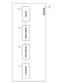
- FIG. 2 is a diagram illustrating an example of a functional block diagram of a tracking device.
- FIG. 2 is a diagram illustrating an example of a hardware configuration of a tracking device.
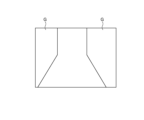
- 10 is a diagram for explaining an example of a process in which the tracking device detects a predetermined moving object;
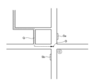
- 11 is a diagram for explaining another example of a process in which the tracking device detects a predetermined moving object;
- FIG. FIG. 2 is a diagram illustrating an example of information processed by the tracking device.
- 11 is a diagram for explaining another example of a process in which the tracking device detects a predetermined moving object;
- FIG. FIG. 2 is a diagram illustrating an example of information processed by the tracking device.
- FIG. 11 is a diagram for explaining another example of a process in which the tracking device detects a predetermined moving object;
- FIG. 11 is a diagram for explaining another example of a process in which the tracking device detects a predetermined moving object;
- FIG. 11 is a diagram for explaining another example of a process in which the tracking device detects a predetermined moving object;
- FIG. 13 is a flowchart showing an example of a process flow of the tracking device.
- FIG. 2 is a diagram illustrating an example of a functional block diagram of a tracking device. 13 is a flowchart showing another example of the process flow of the tracking device.
- 11 is a diagram for explaining another example of a process in which the tracking device detects a predetermined moving object;
- FIG. 2 is a diagram illustrating an example of a functional block diagram of a tracking device.
- 13 is a flowchart showing another example of the process flow of the tracking device.
- 11 is a diagram for explaining another example of a process in which the tracking device
- First Embodiment 1 is a functional block diagram showing an overview of a tracking device 10 according to the first embodiment.
- the tracking device 10 includes a person tracking unit 11, a moving object detection unit 12, and a moving object tracking unit 13.
- the person tracking unit 11 tracks the tracked person within an image (moving image).
- the moving object detection unit 12 detects a moving object that performs an action that satisfies a time condition based on the timing at which the tracked person was lost, and a positional condition based on the position at which the tracked person was lost.
- the moving object tracking unit 13 tracks the moving object detected by the moving object detection unit 12.
- a moving body that performs an action that satisfies a time condition based on the timing at which the tracked person was lost, and a positional condition based on the position at which the tracked person was lost is estimated as the moving body in which the tracked person is riding.
- the tracking device 10 of the second embodiment is a specific embodiment of the tracking device 10 of the first embodiment. That is, the tracking device 10 estimates that a moving object that performs an action that satisfies a time condition based on the timing at which the tracking target person is lost and a positional condition based on the position at which the tracking target person is lost is a moving object ridden by the tracking target person. Then, the tracking device 10 tracks the moving object estimated to be ridden by the tracking target person. This will be described in detail below.
- the hardware configuration of the tracking device 10 is realized by any combination of hardware and software.
- the software includes programs that are stored in the device before it is shipped, and programs downloaded from recording media such as CDs (Compact Discs) and servers on the Internet.
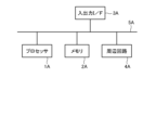
- FIG. 2 is a block diagram illustrating an example of the hardware configuration of the tracking device 10.
- the tracking device 10 has a processor 1A, a memory 2A, an input/output interface 3A, a peripheral circuit 4A, and a bus 5A.
- the peripheral circuit 4A includes various modules.
- the tracking device 10 does not have to have the peripheral circuit 4A.
- the tracking device 10 may be composed of multiple devices that are physically and/or logically separated. In this case, each of the multiple devices can have the above hardware configuration.
- the bus 5A is a data transmission path for the processor 1A, memory 2A, peripheral circuit 4A, and input/output interface 3A to send and receive data to each other.
- the processor 1A is an arithmetic processing device such as a CPU or a GPU (Graphics Processing Unit).
- the memory 2A is a memory such as a RAM (Random Access Memory) or a ROM (Read Only Memory).
- the input/output interface 3A includes interfaces for acquiring information from an input device, an external device, an external server, an external sensor, a camera, etc., and interfaces for outputting information to an output device, an external device, an external server, etc.
- the input/output interface 3A also includes an interface for connecting to a communication network such as the Internet.
- Examples of input devices include a keyboard, a mouse, a microphone, a physical button, a touch panel, etc.
- Examples of output devices include a display, a speaker, a printer, a mailer, etc.
- the processor 1A can issue commands to each module and perform calculations based on the results of those calculations.
- the tracking device 10 of this embodiment has a person tracking unit 11, a moving object detection unit 12, and a moving object tracking unit 13.
- the person tracking unit 11 tracks a tracked person within an image. To achieve this process, the person tracking unit 11 acquires an image. The person tracking unit 11 also acquires information indicating the external appearance features of the tracked person. Then, based on the external appearance features of the tracked person, the person tracking unit 11 detects the tracked person within the acquired image, and tracks the tracked person within the image.
- Image is a concept that includes moving images.
- Image acquisition is achieved by any means.
- the tracking device 10 is configured to be able to communicate with one or more cameras (such as surveillance cameras) installed on the road or at street corners. The cameras may then transmit the images they generate to the tracking device 10.
- the images generated by the cameras may be stored in any storage means.
- the images stored in the storage means may then be input to the tracking device 10 by manual operation by the user. Input of images to the tracking device 10 may be performed by real-time processing or batch processing.
- the person tracking unit 11 can acquire images input to the tracking device 10 in this way. Note that the person tracking unit 11 may acquire images by other means.
- “Acquisition” includes at least one of the following: the device goes to retrieve data or information stored in another device or storage medium (active acquisition), and the device inputs data or information output from another device (passive acquisition). Examples of active acquisition include making a request or inquiry to another device and receiving a reply, and accessing and reading information from another device or storage medium. An example of passive acquisition is receiving information that is distributed (or transmitted, push notification, etc.). Furthermore, “acquisition” may mean selecting and acquiring data or information from received data or information, or selecting and receiving distributed data or information.
- the "information indicating the external appearance features of the person to be tracked” is input to the tracking device 10 by the user.
- the user may input the external appearance features of the person to be tracked to the tracking device 10.
- the user may input an image of the person to be tracked to the tracking device 10.
- the person tracking unit 11 may then analyze the image and extract the external appearance features of the person to be tracked.
- the "appearance features of the person being tracked” include, but are not limited to, facial features, body features, clothing features, possessions features, shoe features, etc.
- the person tracking unit 11 detects a person to be tracked from images taken by multiple cameras based on the external appearance features of the person to be tracked. The person tracking unit 11 then tracks the person to be tracked within the images.
- the detection and tracking of people within images can be achieved using any technology.
- the person tracking unit 11 When the person tracking unit 11 loses sight of the tracked person, it inputs information indicating the time when the tracked person was lost and the position where the tracked person was lost to the moving object detection unit 12.
- “Losing sight of a tracked person” means that a tracked person who was detected in an image and tracked in the image can no longer be detected in the image. A tracked person who was previously detected can be lost due to reasons such as blending into a crowd, entering a building, or entering a camera's blind spot. While the tracked person is out of sight, there is a possibility that the tracked person may board a moving body. In this case, the tracking device 10 of this embodiment can estimate the moving body that the tracked person is riding on if the tracked person boards a moving body while the tracked person has been lost in sight of the image.
- the "information indicating the timing at which the tracked person was lost" is indicated by a date and time. For example, the date and time of the capture of the frame image at which the tracked person was lost is identified based on the timestamp attached to the image.
- Information indicating the position where the tracked person was lost may include information indicating the camera that generated the image in which the tracked person was detected until just before the tracked person was lost, or the installation position of that camera.
- information indicating the position where the tracked person was lost may include information indicating the position in the image in which the tracked person was detected until just before the tracked person was lost.
- the person tracking unit 11 may input the above information to the moving object detection unit 12 in response to losing sight of the tracked person. Additionally, the person tracking unit 11 may input the above information to the moving object detection unit 12 in a case where the tracked person is not detected from any image even after a predetermined time has elapsed after the tracked person is lost.
- the predetermined time is a time that is determined in advance.
- the moving object detection unit 12 detects a moving object that performs an action that satisfies a time condition based on the timing at which the tracked person was lost, and a positional condition based on the position at which the tracked person was lost. In response to receiving the above information from the person tracking unit 11, the moving object detection unit 12 can start the process of detecting moving objects as described above.
- a “mobile object” is an object that a person rides on and moves around, including, but not limited to, vehicles that move on land such as automobiles, motorcycles, buses, taxis, and trains, objects that move on the sea such as ships and boats, and objects that move through the air such as airplanes and helicopters.
- the moving object detection unit 12 can execute at least one of the following detection process examples 1 to 3.
- the "action satisfying the time condition and the position condition" in the detection processing example 1 is an action of starting after the timing at which the tracked person is lost, at a position within a reference distance from the position at which the tracked person is lost. Note that "after the timing at which the tracked person is lost” may be replaced with "after the timing at which the tracked person is lost and before a predetermined time has elapsed since the tracking person was lost.”
- the reference distance is a predetermined distance.
- the predetermined time is a predetermined time.
- the "starting action” is the action of starting to move from a stopped position.
- the moving object detection unit 12 analyzes an image and detects from the image a moving object that has performed an action that satisfies a time condition and a position condition.
- the image to be analyzed is, for example, an image acquired by the person tracking unit 11 (an image from a surveillance camera).
- the image to be analyzed here is an image that was generated (taken) after the image in which the tracked person was lost.
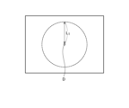
- position D where the tracked person was lost is shown as a position on the image.
- the moving object detection unit 12 identifies an area within this image that is within a reference distance L1 from position D where the tracked person was lost.
- the moving object detection unit 12 detects a moving object that starts out within the identified area after the time when the tracked person was lost (or after that and before a predetermined time has passed since the person was lost).
- the distance used by the moving object detection unit 12 may be the distance within the image or the actual distance (same below).
- the moving object detection unit 12 may calculate the actual distance from the distance within the image by any means.
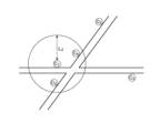
- FIG. 4 Another specific example of the process of the moving object detection unit 12 will be described.
- a plurality of cameras C1 to C5 are installed relatively close to each other.
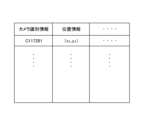
- position information indicating the installation positions of each of the plurality of cameras C1 to C5 is registered in advance in the tracking device 10.
- the position where the tracking target person was lost is shown as the installation position of the camera.
- the moving object detection unit 12 identifies cameras installed in an area within a reference distance L2 from the installation position of the camera (camera C1 in the example of FIG. 4) that lost the tracking target person.
- three cameras C1 , C2, and C4 are identified.
- Such identification of the cameras can be realized based on the position information of multiple cameras as shown in FIG. 5, for example.
- the moving object detection unit 12 detects a moving object that starts moving within the images generated by the identified cameras C1 , C2 , and C4 after the tracking target person is lost (or after that and before a predetermined time has elapsed since the tracking target person was lost).
- the mobile object detection unit 12 detects a mobile object that has performed an action that satisfies a time condition and a location condition, based on the boarding and alighting positions of public transportation and a timetable.
- the boarding and alighting locations and timetables of public transport are determined in advance. Therefore, information indicating the boarding and alighting locations of public transport and the timetables are registered in advance in the tracking device 10.
- An example of public transportation is a bus.
- the boarding and disembarking location is a bus stop.
- Another example of public transportation is a train.
- the boarding and disembarking location is a train station.
- Another example of public transportation is a boat.
- the boarding and disembarking location is a boat dock.
- Another example of public transportation is an airplane.
- the boarding and disembarking location is an airport.
- the mobile object detection unit 12 identifies a public transportation boarding and alighting location within a specified distance from the location where the tracked person was lost. Then, based on the timetable of the identified boarding and alighting location, the mobile object detection unit 12 detects a mobile object that departs from the boarding and alighting location after the tracked person was lost (or after that and before a specified time has elapsed since the person was lost).
- Detection processing example 2 In the case assumed in this example, as shown in Fig. 6, cameras C1 and C2 are installed at positions to capture images of the vicinity of the entrance Ep where people walk into facility F and the vicinity of the exit Ev of the parking lot of facility F. Cameras C1 and C2 cannot capture images of the parking lot of facility F. Therefore, the images generated by cameras C1 and C2 do not capture a scene of a person getting on a moving object in the parking lot. And no camera is installed in facility F. Or, a camera is installed in facility F, but the tracking device 10 cannot acquire images from the camera installed in facility F.
- the "facility" has a parking lot.
- the facility may be a department store, supermarket, amusement park, etc., or it may be something else.
- the moving body detection unit 12 can estimate the moving body in which the person to be tracked is riding.
- the "action that satisfies the time and position conditions" in detection processing example 2 is the action of exiting from an exit of a parking lot of a facility that is within a predetermined distance from the location where the tracked person was lost, after the first predetermined time has elapsed since the tracked person was lost. Note that "after the first predetermined time has elapsed since the tracked person was lost” may be replaced with "after the first predetermined time has elapsed since the tracked person was lost, and before the second predetermined time has elapsed.”
- the first predetermined time is the travel time required to travel from the entrance of the facility to the parking lot of the facility.
- the second predetermined time is a predetermined time.
- the predetermined distance is a predetermined distance.
- information about each of a number of facilities is registered in advance in the tracking device 10.
- the information about the facilities includes location information indicating the location of each facility, and information indicating the distance from the entrance of each facility to the parking lot. If each facility has multiple entrances, the distance from each entrance to the parking lot may be indicated.
- the information about the facilities may further include information indicating the location of each entrance and the exit of the parking lot.
- the moving object detection unit 12 Based on such facility-related information, the moving object detection unit 12 identifies a facility that is within a predetermined distance from the position where the tracked person was lost. The moving object detection unit 12 then calculates the travel time that is the first predetermined time based on the distance from the entrance of the identified facility to the parking lot and the estimated travel speed of the tracked person. If the identified facility has multiple entrances, the moving object detection unit 12 identifies the entrance closest to the position where the tracked person was lost. The moving object detection unit 12 then calculates the travel time based on the distance from the identified entrance to the parking lot.
- the moving object detection unit 12 detects a moving object that exits from the exit of the parking lot of the identified facility after a first predetermined time (calculated travel time) from the time the tracked person was lost (or after that and before the time when a second predetermined time has elapsed since the person was lost).
- the image to be analyzed is an image generated by a camera that captures the vicinity of the exit of the parking lot of the identified facility. For example, based on location information indicating the installation locations of each of multiple cameras as shown in FIG. 5, a camera that captures the area near the exit of the parking lot of the identified facility is identified.
- the moving object detection unit 12 determines an estimated moving speed of the person to be tracked based on the person information about the person to be tracked, and calculates the above-mentioned moving time based on the determined estimated moving speed.
- the person information indicates at least one of the following: the age, sex, whether or not the person to be tracked is carrying luggage, the size of the luggage, whether or not the person is injured, and the moving speed up to that point.
- the age, sex, whether or not the person being tracked has luggage, the size of the luggage, and whether or not the person is injured may be identified by image analysis. Alternatively, the user may input the age, sex, whether or not the person being tracked has luggage, the size of the luggage, and whether or not the person is injured to the tracking device 10.
- the moving object detection unit 12 can calculate the estimated movement speed of the tracking target, for example, based on this information.
- a speed calculation model is generated in advance, with this person information as input and with the estimated movement speed calculated based on the input person information as output.
- the speed calculation model may be a function, a learning model generated by machine learning, or something else.
- the moving object detection unit 12 inputs person information about the person being tracked into such a speed calculation model, and obtains the estimated movement speed output from the speed calculation model.
- the moving object detection unit 12 may calculate the moving speed of the person to be tracked until the person is lost sight of based on the image, and use the calculation result as the estimated moving speed of the person to be tracked. Calculation of the moving speed of a person detected in an image can be realized using any technology.
- the first predetermined time may be a concept that includes at least one of the time required for a moving object to move within the parking lot and the time required for a person to move within the parking lot, in addition to the travel time required to move from the facility entrance to the facility's parking lot.
- the information about the facility as shown in FIG. 7 may include an estimate of the time required for a moving object to move within the parking lot, and an estimate of the time required for a person to move within the parking lot.
- the moving object detection unit 12 may then calculate the first predetermined time by adding that information to the calculated travel time required to move from the facility entrance to the facility's parking lot.
- the moving body detection unit 12 can estimate the moving body on which the person to be tracked rides.
- the "motion that satisfies the time and position conditions" in detection process example 3 is a motion that appears from behind an object within a predetermined distance from the position where the tracked person was lost after the tracked person was lost. Note that "after the tracked person was lost” may be replaced with "after the tracked person was lost and before a predetermined time has elapsed since the tracked person was lost.”
- the predetermined distance is a distance that is determined in advance.
- the predetermined time is a time that is determined in advance.
- the moving object detection unit 12 analyzes images generated by a camera that generated an image in which the tracked person was lost, and detects from among those images a moving object that performed an action that satisfies a time condition and a position condition.
- the image to be analyzed here is an image that was generated (taken) after the image in which the tracked person was lost.
- the moving object detection unit 12 identifies an object area (area behind an object) within a specified distance from the position where the tracked person was lost in the image to be analyzed. The moving object detection unit 12 then detects a moving object that appears from the identified object area after the tracked person was lost (or after that and before a specified time has passed since the person was lost). Note that information indicating one or more object areas in the image may be registered in advance in the tracking device 10.
- images generated by a plurality of cameras C1 and C2 installed at each of a plurality of exits of the tunnel T as shown in Fig. 10 may be subject to the process of detecting a moving object. That is, the moving object detection unit 12 may analyze the images generated by such a plurality of cameras and detect a moving object that has performed an action that satisfies the above-mentioned time and position conditions from among the images.
- the moving object detection unit 12 can identify cameras installed at multiple tunnel exits within a specified distance from the position where the tracked person was lost, based on location information indicating the installation position of each of the multiple cameras as shown in FIG. 5, and map information indicating the shape and position of the tunnel.
- the moving object tracking unit 13 tracks the moving object detected by the moving object detection unit 12 (hereinafter, the "tracked moving object”).
- the moving object tracking unit 13 can execute at least one of the following moving object tracking examples 1 and 2.
- the moving object tracking unit 13 acquires an image.
- the moving object tracking unit 13 also acquires information indicating the external features of the moving object to be tracked.
- the moving object tracking unit 13 detects the moving object to be tracked within the acquired image based on the external features of the moving object to be tracked, and tracks the moving object to be tracked within the image.
- Image acquisition is achieved by the same means as image acquisition by the person tracking unit 11.
- the tracking device 10 may display an image of the moving object to be tracked detected by the moving object detection unit 12 on a display. The user may then identify the external features of the moving object to be tracked based on the image and input the identified external features to the tracking device 10. Additionally, the moving object tracking unit 13 may analyze the image of the moving object to be tracked detected by the moving object detection unit 12 and extract the external features of the moving object to be tracked.
- the “feature values of the external appearance of the moving object to be tracked” are the information written on the license plate (such as the number), the vehicle type, the color of the moving object, the design of the moving object, etc. Also, if the moving object to be tracked is a bus, the feature values of the external appearance of the moving object to be tracked are the route name, route number, destination, etc., displayed on the bulletin board on the moving object to be tracked.
- the moving object tracking unit 13 detects the moving object to be tracked from images captured by multiple surveillance cameras based on the external features of the moving object to be tracked. The moving object tracking unit 13 then tracks the moving object to be tracked within the images.
- the detection and tracking of moving objects within images can be achieved using any technology.
- Tracking process example 2 When the moving object to be tracked is a public vehicle, as part of the tracking process, the moving object tracking unit 13 can identify one or more destinations of the moving object to be tracked and the scheduled time of arrival at each destination based on the timetable of the moving object to be tracked.
- the moving object tracking unit 13 can output the tracking results.
- the moving object tracking unit 13 may output information indicating the current position of the moving object to be tracked. This information may be information in which the current position of the moving object to be tracked is mapped on a map, or may be other information.
- the moving object tracking unit 13 may output the destinations to which the moving object to be tracked is heading and the scheduled time of arrival at each destination. The output of this information is realized via any output device such as a display, a projection device, a printer, etc.
- the tracking device 10 tracks the target person within the image (S10).
- the tracking device 10 continues to track the target person while it is able to detect the target person within the image (No in S11).
- the tracking device 10 When the tracking device 10 loses sight of the tracked person (Yes in S11), it identifies the location and timing at which the tracked person was lost (S12). The tracking device 10 then executes a process to detect a moving object that has performed an action that satisfies a time condition based on the time at which the tracked person was lost, and a positional condition based on the location at which the tracked person was lost (S13). Next, the tracking device 10 starts tracking the moving object detected in S13 (S14).
- the tracking device 10 may output information to that effect and end the process of detecting the moving object.
- the tracking device 10 of this embodiment also detects a moving object that has performed the characteristic "action that satisfies the time and position conditions" described above.
- a tracking device 10 can accurately detect a moving object that may have been ridden by a person to be tracked. Furthermore, such a tracking device 10 can accurately estimate the moving object that the person to be tracked is riding on, even if the person to be tracked rides on a moving object in a blind spot of the camera, such as a parking lot of a facility or behind an object.
- the tracking device 10 of this embodiment has a function of estimating the moving body carrying the person to be tracked when multiple moving bodies that have performed "an action that satisfies a time condition and a position condition" are detected. This will be described in detail below.
- FIG. 12 shows an example of a functional block diagram of the tracking device 10 of this embodiment.
- the tracking device 10 of this embodiment has a person tracking unit 11, a moving object detection unit 12, a moving object tracking unit 13, and an estimation unit 14.
- the configurations of the person tracking unit 11 and the moving object detection unit 12 are the same as those of the first and second embodiments.
- the moving object tracking unit 13 tracks the multiple moving objects.
- the tracking method is as described in the second embodiment.
- the other configurations of the moving object tracking unit 13 are the same as those in the first and second embodiments.
- the estimation unit 14 estimates the moving body carrying the person to be tracked from among the multiple moving bodies based on the operation history of the multiple moving bodies after tracking has started.
- the operation history indicates at least one of whether or not a traffic signal was run, the number of times a traffic signal was run, whether or not the legal speed limit was exceeded, the degree of the speed limit exceeded, the number of lane changes, and the movement route.
- the degree of the speed limit exceeded indicates how much the legal speed was exceeded (the difference from the legal speed limit).
- Such an operation history can be generated based on an image that shows the moving object to be tracked.
- the moving object tracking unit 13 may generate an operation history by tracking the moving object to be tracked and analyzing an image that shows the moving object to be tracked.
- the person being tracked is a fugitive, they are likely to frequently ignore traffic signals, exceed the legal speed limit, change lanes, etc. Furthermore, they are likely to exceed the legal speed limit to a greater extent. From this perspective, it is possible to estimate the vehicle in which the person being tracked is riding from among multiple moving vehicles.
- the cameras installed on that movement path can be identified. Then, by performing face recognition processing based on the images generated by the identified cameras, the degree of facial similarity between the person riding on the moving object to be tracked and the person to be tracked is calculated. Based on the results of such face recognition processing, it is possible to estimate the moving object on which the person to be tracked is riding.
- the estimation unit 14 estimates the moving body in which the person to be tracked is riding from among the multiple moving bodies to be tracked based on the operation history described above.
- a possibility calculation model is generated in advance, which takes the above-mentioned operation history and similarity in face recognition processing as input, and outputs the possibility that the tracked person is riding there (hereinafter, may be referred to as the "first possibility") calculated based on them.
- the possibility calculation model may be a function, a learning model generated by machine learning, or something else.
- the estimation unit 14 inputs the operation history and similarity in face recognition processing of each tracked moving object into such a possibility calculation model, and obtains the first possibility output from the possibility calculation model.
- the possibility calculation model is configured so that the first possibility becomes higher when a traffic light is run.
- the possibility calculation model is also configured so that the more times traffic lights are run, the higher the first possibility becomes.
- the possibility calculation model is also configured so that the first possibility becomes higher when the legal speed limit is exceeded.
- the possibility calculation model is also configured so that the first possibility becomes higher the greater the degree to which the legal speed limit is exceeded.
- the possibility calculation model is also configured so that the first possibility becomes higher the more times lane changes are made.
- the possibility calculation model is also configured so that the first possibility becomes higher the higher the similarity obtained by the face recognition process.
- the likelihood calculation model calculates an evaluation point for each moving object to be tracked. For example, additional points are defined in advance for certain actions such as ignoring traffic signals, exceeding the legal speed limit, changing lanes, etc. Additional points may be defined according to the number of times or the degree of exceeding the legal speed limit. Additionally, additional points may be defined according to the degree of similarity obtained by the face recognition process.
- the likelihood calculation model calculates the sum of the added points as the evaluation points for each moving object being tracked.
- the possibility calculation model calculates a first possibility for each tracked moving object based on the evaluation points for each tracked moving object.
- the possibility calculation model calculates a first possibility for each tracked moving object based on the evaluation points for each tracked moving object.
- information that associates the evaluation points with the first possibilities such as "evaluation points P 0 to P 1 : first possibility 0 to 10%” and “evaluation points P 1 to P 2 : first possibility 10 to 20%”, may be generated in advance and stored in the tracking device 10. Then, the possibility calculation model may specify the first possibility corresponding to the evaluation points of each tracked moving object based on such information.
- the first possibility for each tracked moving object may be calculated by dividing the evaluation point of each tracked moving object by the sum of the evaluation points of the multiple tracked moving objects.
- the estimation unit 14 can output the estimation result.
- the estimation unit 14 may output the moving body with the highest first possibility calculated as described above as the estimation result of the moving body carrying the tracked person.
- the estimation unit 14 may output the moving body with the first possibility calculated as described above that is equal to or greater than a predetermined threshold as the estimation result of the moving body carrying the tracked person.
- the estimation unit 14 may display a list of the multiple moving bodies to be tracked in order of the first possibility.
- the estimation unit 14 may display the estimation result in real time and update the content in real time.
- the tracking device 10 tracks the target person within the image (S20). The tracking device 10 continues to track the target person while it is able to detect the target person within the image (No in S21).
- the tracking device 10 When the tracking device 10 loses sight of the tracked person (Yes in S21), it identifies the location and timing at which the tracked person was lost (S22).Then, the tracking device 10 executes a process to detect a moving object that has performed an action that satisfies a time condition based on the timing at which the tracked person was lost, and a positional condition based on the location at which the tracked person was lost (S23).
- the tracking device 10 starts tracking the moving object (S25).
- the tracking device 10 starts tracking the multiple detected moving objects (S26). Then, based on the operation history of the multiple moving objects after tracking has started, the tracking device 10 estimates which moving object the tracked person is riding on from among the multiple moving objects, and outputs the estimation result (S27). While tracking the multiple moving objects, the tracking device 10 can continue to collect the operation history of the multiple moving objects, estimate the moving object the tracked person is riding on, and output the estimation result.
- the tracking device 10 may output information indicating that fact and end the process of detecting the moving object.
- the rest of the configuration of the tracking device 10 in this embodiment is the same as in the first and second embodiments.
- the tracking device 10 of this embodiment can provide the same effects as the first and second embodiments. Furthermore, when multiple moving objects that have performed "actions that satisfy the time and location conditions" are detected, the tracking device 10 of this embodiment can track the multiple moving objects and estimate the moving object carrying the person to be tracked based on the operation history of each moving object after tracking begins.
- the tracking device 10 of this embodiment has a function of estimating the moving body carrying the person to be tracked from among multiple moving bodies that depart from multiple predetermined boarding and alighting positions, when the multiple moving bodies are detected as moving bodies that have performed "an action that satisfies a time condition and a position condition".
- the multiple moving bodies that depart from multiple predetermined boarding and alighting positions include a train that departs from a station, a bus that departs from a bus stop, a ship that departs from a wharf, an airplane that departs from an airport, etc. The details will be described below.
- FIG. 12 shows an example of a functional block diagram of the tracking device 10 of this embodiment.
- the tracking device 10 of this embodiment has a person tracking unit 11, a moving object detection unit 12, a moving object tracking unit 13, and an estimation unit 14.
- the configurations of the person tracking unit 11, the moving object detection unit 12 to the moving object tracking unit 13 are the same as those of the first to third embodiments.
- the estimation unit 14 estimates from among them which moving object the person to be tracked is riding in.
- multiple moving objects departing from multiple predetermined boarding and alighting positions include a train departing from a station, a bus departing from a bus stop, a ship departing from a dock, an airplane departing from an airport, etc.
- the estimation unit 14 estimates the moving body in which the tracked person is riding from among the multiple moving bodies based on the movement path of the tracked person up until the time when the person was lost and the positional relationship with each of the multiple boarding and alighting points.
- the movement path of the tracked person up until the time when the person was lost can be identified based on the tracking results by the person tracking unit 11, for example.
- Fig. 14 shows a moving path Q of the tracked person up to the time of losing sight of the person, a plurality of boarding and alighting positions S a and S b , and a position D where the person was lost sight of the person.
- the tracked person gets on the moving body from boarding and alighting position S a
- the tracked person reaches boarding and alighting position S a by taking a detour.
- the tracked person gets on the moving body from boarding and alighting position S b
- the tracked person reaches boarding and alighting position S b by the shortest route.
- the estimation unit 14 estimates that the tracked person boarded the moving body from boarding/alighting position Sb . That is, based on the movement path of the tracked person up until the time of losing sight of the person and the positional relationship between each of the multiple boarding/alighting positions, the estimation unit 14 specifies the boarding/alighting position that will be reached via the shortest route, or the boarding/alighting position that will be reached with the smallest deviation from the shortest route. Then, the estimation unit 14 estimates that the tracked person boarded the moving body from the specified boarding/alighting position.
- the shortest route can be determined by a route search that sets the starting point at any position on the path Q of the person being tracked up until the time of loss of sight, and sets each boarding or alighting location as the destination. If the route is the same as the shortest route calculated by the route search, it can be determined to be the shortest route, and if it is different, it can be determined to be a longer route. If the route to each boarding or alighting location is determined to be the shortest route, the starting point can be changed to another position on the path Q, and the same process can be repeated until it is determined that one of the routes is not the shortest route.
- the deviation from the shortest route is indicated by the difference in distance between the first route and the second route, or the difference in the time required for travel. The larger the difference, the greater the deviation from the shortest route.
- the first route is, for example, "the shortest route calculated by route search with an arbitrary position on the movement path Q of the tracked person up to the time of loss as the starting point, and each boarding and disembarking position as the destination point.”
- the second route is, for example, "a route with the same starting point and destination as the first route, which travels from the starting point to the position where the tracked person was lost along the movement path of the tracked person, and from there to the destination point is the shortest route calculated by route search.”
- the estimation unit 14 may calculate and output the probability of boarding each moving object.
- a pre-generated probability calculation model for calculating the probability may be used.
- the probability calculation model may be a function, a learning model generated by machine learning, or something else.
- the estimation unit 14 may use such a probability calculation model to calculate the probability.
- the probability calculation model may be configured to, for example, accept input of the judgment result of whether or not the route is the shortest route as described above.
- the probability calculation model is configured to calculate the probability of boarding a moving body that departs from a boarding/alighting location that is judged to be the shortest route as relatively high.
- the probability calculation model is configured to calculate the probability of boarding a moving body that departs from a boarding/alighting location that is judged not to be the shortest route as relatively low.
- the probability calculation model may also be configured to receive, for example, the input of the judgment result of deviation from the shortest route described above.
- the probability calculation model is configured to calculate, as relatively high, the probability of boarding a moving object that departs from a boarding/alighting location that results in a route that deviates less from the shortest route.
- the probability calculation model is also configured to calculate, as relatively low, the probability of boarding a moving object that departs from a boarding/alighting location that results in a route that deviates more from the shortest route.
- the probability calculation model may calculate the probability using a weighting that is preset for a moving body departing from each boarding/alighting position.
- the probability calculation model is configured to calculate a higher probability for a moving body with a higher weighting.
- the probability calculation model is configured to calculate a lower probability for a moving body with a lower weighting.
- the user sets a weight for each boarding/alighting position in advance and registers it in the tracking device 10.
- the probability calculation model calculates the probability using the registered weighting.
- the estimation unit 14 may have a configuration similar to that of the third embodiment.
- the rest of the configuration of the tracking device 10 of this embodiment is the same as in the first to third embodiments.
- the tracking device 10 of this embodiment provides the same effects as the first to third embodiments. Furthermore, when multiple moving bodies that depart from multiple predetermined boarding and alighting positions are detected as moving bodies that have performed "an action that satisfies the time and positional conditions," the tracking device 10 of this embodiment estimates which moving body the tracked person is riding in from among them. The tracking device 10 estimates which moving body the tracked person is riding in from among the multiple moving bodies based on the movement path of the tracked person up until the time it was lost sight of and the positional relationship between each of the multiple boarding and alighting positions. Such a tracking device 10 can accurately estimate which moving body the tracked person is riding in.
- the tracking device 10 identifies "the action of leaving the exit of a parking lot of a facility within a predetermined distance from the position where the tracked person was lost" through image analysis.
- the tracking device 10 may detect a moving object that performed such an action based on the operation history of the exit gate of the parking lot. The operation history indicates the timing when the exit gate was opened.
- the tracking device 10 and the parking lot exit gate control system are configured to be able to communicate with each other.
- the tracking device 10 acquires the operation history of the parking lot exit gate from the system, and detects the moving object that has performed the above-mentioned exit operation based on the acquired operation history.
- a camera may be installed near the exit gate of the parking lot to capture images of the moving object exiting the parking lot.
- the tracking device 10 may then obtain the external features of the moving object being tracked based on the images generated by this camera.
- a person tracking means for tracking a target person in an image a moving object detection means for detecting a moving object that has performed an action that satisfies a time condition based on a timing at which the tracking target person was lost and a positional condition based on a position at which the tracking target person was lost; a moving object tracking means for tracking the detected moving object;
- a tracking device having 2. The tracking device according to 1, wherein the action that satisfies the time condition and the positional condition is an action of starting at a timing after the timing at which the tracked person is lost, at a position within a reference distance from the position at which the tracked person is lost. 3.
- the action that satisfies the time condition and the positional condition is an action of exiting from an exit of a parking lot of a facility that is within a predetermined distance from the position where the tracking target person was lost after a predetermined time has elapsed from the position where the tracking target person was lost, 3.
- the tracking device according to claim 1 or 2 wherein the predetermined time is a travel time required to travel from an entrance of the facility to a parking lot of the facility. 4.
- the moving object detection means 4.
- the tracking device according to claim 3 further comprising: determining a moving speed of the person to be tracked based on person information relating to the person to be tracked; and calculating the moving time based on the determined moving speed. 5.
- the tracking device wherein the person information indicates at least one of the age, sex, whether or not the person to be tracked has luggage, the size of the luggage, whether or not the person is injured, and a moving speed up to that point.
- the action that satisfies the time condition and the positional condition is an action of appearing from behind an object within a predetermined distance from a position where the tracked person was lost, at a timing after the timing where the tracked person was lost. 7.
- the moving object tracking means When a plurality of moving objects that perform an action that satisfies the time condition and the position condition are detected, the plurality of moving objects are tracked; A tracking device described in any one of 1 to 6, further comprising an estimation means for estimating the moving body in which the tracked person is riding from among the multiple moving bodies based on the operation history of the multiple moving bodies after tracking begins.
- the operation history indicates at least one of whether or not a traffic signal was run, the number of times a traffic signal was run, whether or not a legal speed limit was exceeded, the degree of the legal speed limit exceeded, the number of lane changes, and a travel route.
- the operation history indicates a movement route, 9.
- the tracking device wherein the estimation means estimates that the moving body in which the tracked person is riding is based on a face recognition process based on an image captured by a camera installed on the moving path of the moving body.
- the tracking device further comprising an estimation means for estimating, when a plurality of moving bodies departing from a plurality of predetermined boarding and alighting positions are detected as a plurality of moving bodies that have performed an action that satisfies the time condition and the positional condition, the moving body in which the person to be tracked is riding, from among the plurality of moving bodies, based on a movement path of the person to be tracked until the person was lost sight of and a positional relationship between the plurality of boarding and alighting positions.
- One or more computers Track the target person in the image, Detecting a moving object that has performed an action that satisfies a time condition based on a timing at which the tracking target person was lost and a positional condition based on a position at which the tracking target person was lost; A tracking method for tracking the detected moving object.
- the computer A person tracking means for tracking a target person within an image; a moving object detection means for detecting a moving object that has performed an action that satisfies a time condition based on a timing at which the tracking target person was lost and a positional condition based on a position at which the tracking target person was lost; a moving object tracking means for tracking the detected moving object;
- a program that functions as a
Landscapes
- Business, Economics & Management (AREA)
- Tourism & Hospitality (AREA)
- Health & Medical Sciences (AREA)
- Economics (AREA)
- General Health & Medical Sciences (AREA)
- Human Resources & Organizations (AREA)
- Marketing (AREA)
- Primary Health Care (AREA)
- Strategic Management (AREA)
- Physics & Mathematics (AREA)
- General Business, Economics & Management (AREA)
- General Physics & Mathematics (AREA)
- Engineering & Computer Science (AREA)
- Theoretical Computer Science (AREA)
- Image Analysis (AREA)
Abstract
Description
追跡対象の人物を画像内で追跡する人物追跡手段と、
前記追跡対象の人物を見失ったタイミングに基づく時間的条件、及び前記追跡対象の人物を見失った位置に基づく位置的条件を満たす動作を行った移動体を検出する移動体検出手段と、
検出された前記移動体を追跡する移動体追跡手段と、
を有する追跡装置が提供される。
1つ以上のコンピュータが、
追跡対象の人物を画像内で追跡し、
前記追跡対象の人物を見失ったタイミングに基づく時間的条件、及び前記追跡対象の人物を見失った位置に基づく位置的条件を満たす動作を行った移動体を検出し、
検出された前記移動体を追跡する追跡方法が提供される。
コンピュータを、
追跡対象の人物を画像内で追跡する人物追跡手段、
前記追跡対象の人物を見失ったタイミングに基づく時間的条件、及び前記追跡対象の人物を見失った位置に基づく位置的条件を満たす動作を行った移動体を検出する移動体検出手段、
検出された前記移動体を追跡する移動体追跡手段、
として機能させるプログラムが提供される。
図1は、第1の実施形態に係る追跡装置10の概要を示す機能ブロック図である。追跡装置10は、人物追跡部11と、移動体検出部12と、移動体追跡部13とを有する。
「概要」
第2の実施形態の追跡装置10は、第1の実施形態の追跡装置10を具体化したものである。すなわち、追跡装置10は、追跡対象の人物を見失ったタイミングに基づく時間的条件、及び追跡対象の人物を見失った位置に基づく位置的条件を満たす動作を行った移動体を、その追跡対象の人物が乗った移動体として推定する。そして、追跡装置10は、追跡対象の人物が乗ったと推定した移動体を追跡する。以下、詳細に説明する。
追跡装置10のハードウエア構成の一例を説明する。追跡装置10の各機能部は、ハードウエアとソフトウエアの任意の組み合わせによって実現される。その実現方法、装置にはいろいろな変形例があることは、当業者には理解されるところである。ソフトウエアは、予め装置を出荷する段階から格納されているプログラムや、CD(Compact Disc)等の記録媒体やインターネット上のサーバ等からダウンロードされたプログラム等を含む。
次に、本実施形態の追跡装置10の機能構成を詳細に説明する。図1に、本実施形態の追跡装置10の機能ブロック図の一例を示す。図示するように、本実施形態の追跡装置10は、人物追跡部11と、移動体検出部12と、移動体追跡部13とを有する。
検出処理例1の「時間的条件及び位置的条件を満たす動作」は、追跡対象の人物を見失ったタイミングよりも後に、追跡対象の人物を見失った位置から基準距離以内の位置で発進する動作である。なお、「追跡対象の人物を見失ったタイミングよりも後」を「追跡対象の人物を見失ったタイミングよりも後かつ見失ってから所定時間経過したタイミングより前」に置き換えてもよい。基準距離は、予め定められた距離である。所定時間は、予め定められた時間である。
当該例で想定するケースでは、図6に示すように、施設Fの人が歩いて入る入口Ep付近、及び施設Fの駐車場の出口Ev付近を撮影する位置に、カメラC1及びC2が設置される。カメラC1及びC2は、施設Fの駐車場の様子を撮影することはできない。このため、カメラC1及びC2が生成した画像においては、その駐車場において人が移動体に乗りこむシーンが写っていない。そして、施設F内にはカメラが設置されていない。又は、施設F内にカメラが設置されているが、追跡装置10が施設F内に設置されたカメラの画像を取得できない。
当該例で想定するケースでは、図8及び図9に示すように、カメラが生成した画像の中に、カメラの死角となる物陰が存在する。図8では、トンネルTの中が物陰となっている。図9では、建物Gに隠れる部分が物陰となっている。
当該例では、移動体追跡部13は、画像を取得する。また、移動体追跡部13は、追跡対象の移動体の外観の特徴量を示す情報を取得する。そして、移動体追跡部13は、追跡対象の移動体の外観の特徴量に基づき、取得した画像内で追跡対象の移動体を検出するとともに、画像内でその追跡対象の移動体を追跡する。
追跡対象の移動体が公共の乗り物である場合、追跡処理として、移動体追跡部13は、追跡対象の移動体の1つ又は複数の行き先や、各行き先に到着する予定時刻を、その追跡対象の移動体の時刻表に基づき特定することができる。
本実施形態の追跡装置10によれば、第1の実施形態の追跡装置10と同様の作用効果が実現される。
本実施形態の追跡装置10は、「時間的条件及び位置的条件を満たす動作」を行った移動体が複数検出された場合に、その中から、追跡対象の人物が乗った移動体を推定する機能を有する。以下、詳細に説明する。
本実施形態の追跡装置10は、「時間的条件及び位置的条件を満たす動作」を行った移動体として、予め定められた複数の乗降位置各々から発進した複数の移動体が検出された場合、その中から、追跡対象の人物が乗った移動体を推定する機能を有する。予め定められた複数の乗降位置各々から発進した複数の移動体は、駅から発進した電車や、停留所から発進したバスや、船着き場から発進した船や、空港から発進した飛行機等である。以下、詳細に説明する。
第2の実施形態で説明した例では、追跡装置10は、「追跡対象の人物を見失った位置から所定距離以内にある施設の駐車場の出口から退場する動作」を画像解析で特定した。変形例として、追跡装置10は、駐車場の退場ゲートの動作履歴に基づき、このような動作を行った移動体を検出してもよい。動作履歴は、退場ゲートが開いたタイミングを示す。
1. 追跡対象の人物を画像内で追跡する人物追跡手段と、
前記追跡対象の人物を見失ったタイミングに基づく時間的条件、及び前記追跡対象の人物を見失った位置に基づく位置的条件を満たす動作を行った移動体を検出する移動体検出手段と、
検出された前記移動体を追跡する移動体追跡手段と、
を有する追跡装置。
2. 前記時間的条件及び前記位置的条件を満たす動作は、前記追跡対象の人物を見失ったタイミングよりも後のタイミングにおいて、前記追跡対象の人物を見失った位置から基準距離以内の位置で発進する動作である1に記載の追跡装置。
3. 前記時間的条件及び前記位置的条件を満たす動作は、前記追跡対象の人物を見失ったタイミングから所定時間経過したタイミングよりも後に、前記追跡対象の人物を見失った位置から所定距離以内にある施設の駐車場の出口から退場する動作であり、
前記所定時間は、前記施設の入口から前記施設の駐車場までの移動に要する移動時間である1又は2に記載の追跡装置。
4. 前記移動体検出手段は、
前記追跡対象の人物に関する人物情報に基づき前記追跡対象の人物の移動速度を決定し、決定した移動速度に基づき前記移動時間を算出する3に記載の追跡装置。
5. 前記人物情報は、前記追跡対象の人物の年齢、性別、荷物の有無、荷物の大きさ、ケガの有無、及びそれまでの移動速度の中の少なくとも1つを示す4に記載の追跡装置。
6. 前記時間的条件及び前記位置的条件を満たす動作は、前記追跡対象の人物を見失ったタイミングよりも後のタイミングにおいて、前記追跡対象の人物を見失った位置から所定距離以内にある物陰から出現する動作である1から5のいずれかに記載の追跡装置。
7. 前記移動体追跡手段は、
前記時間的条件及び前記位置的条件を満たす動作を行った複数の前記移動体が検出された場合、複数の前記移動体を追跡し、
追跡開始後の複数の前記移動体の動作履歴に基づき、複数の前記移動体の中から、前記追跡対象の人物が乗った前記移動体を推定する推定手段をさらに有する1から6のいずれかに記載の追跡装置。
8. 前記動作履歴は、信号無視の有無、信号無視の回数、法定速度超過の有無、法定速度超過の度合、車線変更回数、及び移動経路の中の少なくとも1つを示す7に記載の追跡装置。
9. 前記動作履歴は、移動経路を示し、
前記推定手段は、前記移動体の移動経路上に設置されたカメラの画像に基づく顔認証処理で、前記追跡対象の人物が乗っている前記移動体を推定する8に記載の追跡装置。
10. 前記時間的条件及び前記位置的条件を満たす動作を行った複数の前記移動体として、予め定められた複数の乗降位置各々から発進した複数の前記移動体が検出された場合、見失ったタイミングまでの前記追跡対象の人物の移動経路と、複数の前記乗降位置各々との位置関係に基づき、複数の前記移動体の中から、前記追跡対象の人物が乗った前記移動体を推定する推定手段をさらに有する1から9のいずれかに記載の追跡装置。
11. 1つ以上のコンピュータが、
追跡対象の人物を画像内で追跡し、
前記追跡対象の人物を見失ったタイミングに基づく時間的条件、及び前記追跡対象の人物を見失った位置に基づく位置的条件を満たす動作を行った移動体を検出し、
検出された前記移動体を追跡する追跡方法。
12. コンピュータを、
追跡対象の人物を画像内で追跡する人物追跡手段、
前記追跡対象の人物を見失ったタイミングに基づく時間的条件、及び前記追跡対象の人物を見失った位置に基づく位置的条件を満たす動作を行った移動体を検出する移動体検出手段、
検出された前記移動体を追跡する移動体追跡手段、
として機能させるプログラム。
11 人物追跡部
12 移動体検出部
13 移動体追跡部
14 推定部
1A プロセッサ
2A メモリ
3A 入出力I/F
4A 周辺回路
5A バス
Claims (20)
- 追跡対象の人物を画像内で追跡する人物追跡手段と、
前記追跡対象の人物を見失ったタイミングに基づく時間的条件、及び前記追跡対象の人物を見失った位置に基づく位置的条件を満たす動作を行った移動体を検出する移動体検出手段と、
検出された前記移動体を追跡する移動体追跡手段と、
を有する追跡装置。 - 前記時間的条件及び前記位置的条件を満たす動作は、前記追跡対象の人物を見失ったタイミングよりも後のタイミングにおいて、前記追跡対象の人物を見失った位置から基準距離以内の位置で発進する動作である請求項1に記載の追跡装置。
- 前記時間的条件及び前記位置的条件を満たす動作は、前記追跡対象の人物を見失ったタイミングから所定時間経過したタイミングよりも後に、前記追跡対象の人物を見失った位置から所定距離以内にある施設の駐車場の出口から退場する動作であり、
前記所定時間は、前記施設の入口から前記施設の駐車場までの移動に要する移動時間である請求項1に記載の追跡装置。 - 前記移動体検出手段は、
前記追跡対象の人物に関する人物情報に基づき前記追跡対象の人物の移動速度を決定し、決定した移動速度に基づき前記移動時間を算出する請求項3に記載の追跡装置。 - 前記人物情報は、前記追跡対象の人物の年齢、性別、荷物の有無、荷物の大きさ、ケガの有無、及びそれまでの移動速度の中の少なくとも1つを示す請求項4に記載の追跡装置。
- 前記時間的条件及び前記位置的条件を満たす動作は、前記追跡対象の人物を見失ったタイミングよりも後のタイミングにおいて、前記追跡対象の人物を見失った位置から所定距離以内にある物陰から出現する動作である請求項1から5のいずれか1項に記載の追跡装置。
- 前記移動体追跡手段は、
前記時間的条件及び前記位置的条件を満たす動作を行った複数の前記移動体が検出された場合、複数の前記移動体を追跡し、
追跡開始後の複数の前記移動体の動作履歴に基づき、複数の前記移動体の中から、前記追跡対象の人物が乗った前記移動体を推定する推定手段をさらに有する請求項1から6のいずれか1項に記載の追跡装置。 - 前記動作履歴は、信号無視の有無、信号無視の回数、法定速度超過の有無、法定速度超過の度合、車線変更回数、及び移動経路の中の少なくとも1つを示す請求項7に記載の追跡装置。
- 前記動作履歴は、移動経路を示し、
前記推定手段は、前記移動体の移動経路上に設置されたカメラの画像に基づく顔認証処理で、前記追跡対象の人物が乗っている前記移動体を推定する請求項8に記載の追跡装置。 - 前記時間的条件及び前記位置的条件を満たす動作を行った複数の前記移動体として、予め定められた複数の乗降位置各々から発進した複数の前記移動体が検出された場合、見失ったタイミングまでの前記追跡対象の人物の移動経路と、複数の前記乗降位置各々との位置関係に基づき、複数の前記移動体の中から、前記追跡対象の人物が乗った前記移動体を推定する推定手段をさらに有する請求項1から9のいずれか1項に記載の追跡装置。
- 1つ以上のコンピュータが、
追跡対象の人物を画像内で追跡し、
前記追跡対象の人物を見失ったタイミングに基づく時間的条件、及び前記追跡対象の人物を見失った位置に基づく位置的条件を満たす動作を行った移動体を検出し、
検出された前記移動体を追跡する追跡方法。 - 前記時間的条件及び前記位置的条件を満たす動作は、前記追跡対象の人物を見失ったタイミングよりも後のタイミングにおいて、前記追跡対象の人物を見失った位置から基準距離以内の位置で発進する動作である請求項11に記載の追跡方法。
- 前記時間的条件及び前記位置的条件を満たす動作は、前記追跡対象の人物を見失ったタイミングから所定時間経過したタイミングよりも後に、前記追跡対象の人物を見失った位置から所定距離以内にある施設の駐車場の出口から退場する動作であり、
前記所定時間は、前記施設の入口から前記施設の駐車場までの移動に要する移動時間である請求項11に記載の追跡方法。 - 前記1つ以上のコンピュータが、
前記追跡対象の人物に関する人物情報に基づき前記追跡対象の人物の移動速度を決定し、決定した移動速度に基づき前記移動時間を算出する請求項13に記載の追跡方法。 - 前記人物情報は、前記追跡対象の人物の年齢、性別、荷物の有無、荷物の大きさ、ケガの有無、及びそれまでの移動速度の中の少なくとも1つを示す請求項14に記載の追跡方法。
- コンピュータを、
追跡対象の人物を画像内で追跡する人物追跡手段、
前記追跡対象の人物を見失ったタイミングに基づく時間的条件、及び前記追跡対象の人物を見失った位置に基づく位置的条件を満たす動作を行った移動体を検出する移動体検出手段、
検出された前記移動体を追跡する移動体追跡手段、
として機能させるプログラムを記憶する記録媒体。 - 前記時間的条件及び前記位置的条件を満たす動作は、前記追跡対象の人物を見失ったタイミングよりも後のタイミングにおいて、前記追跡対象の人物を見失った位置から基準距離以内の位置で発進する動作である請求項16に記載の記録媒体。
- 前記時間的条件及び前記位置的条件を満たす動作は、前記追跡対象の人物を見失ったタイミングから所定時間経過したタイミングよりも後に、前記追跡対象の人物を見失った位置から所定距離以内にある施設の駐車場の出口から退場する動作であり、
前記所定時間は、前記施設の入口から前記施設の駐車場までの移動に要する移動時間である請求項16に記載の記録媒体。 - 前記移動体検出手段は、
前記追跡対象の人物に関する人物情報に基づき前記追跡対象の人物の移動速度を決定し、決定した移動速度に基づき前記移動時間を算出する請求項18に記載の記録媒体。 - 前記人物情報は、前記追跡対象の人物の年齢、性別、荷物の有無、荷物の大きさ、ケガの有無、及びそれまでの移動速度の中の少なくとも1つを示す請求項19に記載の記録媒体。
Priority Applications (1)
| Application Number | Priority Date | Filing Date | Title |
|---|---|---|---|
| JP2025506511A JPWO2024190067A5 (ja) | 2024-01-18 | 追跡装置、追跡方法、及びプログラム |
Applications Claiming Priority (2)
| Application Number | Priority Date | Filing Date | Title |
|---|---|---|---|
| JP2023041790 | 2023-03-16 | ||
| JP2023-041790 | 2023-03-16 |
Publications (1)
| Publication Number | Publication Date |
|---|---|
| WO2024190067A1 true WO2024190067A1 (ja) | 2024-09-19 |
Family
ID=92754735
Family Applications (1)
| Application Number | Title | Priority Date | Filing Date |
|---|---|---|---|
| PCT/JP2024/001230 Ceased WO2024190067A1 (ja) | 2023-03-16 | 2024-01-18 | 追跡装置、追跡方法、及び記録媒体 |
Country Status (1)
| Country | Link |
|---|---|
| WO (1) | WO2024190067A1 (ja) |
Citations (4)
| Publication number | Priority date | Publication date | Assignee | Title |
|---|---|---|---|---|
| JP2012080221A (ja) * | 2010-09-30 | 2012-04-19 | Jvc Kenwood Corp | 目標追跡装置、目標追跡方法 |
| JP2015019249A (ja) * | 2013-07-11 | 2015-01-29 | パナソニック株式会社 | 追跡支援装置、追跡支援システムおよび追跡支援方法 |
| JP2022155646A (ja) * | 2021-03-31 | 2022-10-14 | ミサワホーム株式会社 | 街区の見守りシステム |
| US11594034B1 (en) * | 2020-08-21 | 2023-02-28 | Vivint, Inc. | Techniques for a smart monitoring system |
-
2024
- 2024-01-18 WO PCT/JP2024/001230 patent/WO2024190067A1/ja not_active Ceased
Patent Citations (4)
| Publication number | Priority date | Publication date | Assignee | Title |
|---|---|---|---|---|
| JP2012080221A (ja) * | 2010-09-30 | 2012-04-19 | Jvc Kenwood Corp | 目標追跡装置、目標追跡方法 |
| JP2015019249A (ja) * | 2013-07-11 | 2015-01-29 | パナソニック株式会社 | 追跡支援装置、追跡支援システムおよび追跡支援方法 |
| US11594034B1 (en) * | 2020-08-21 | 2023-02-28 | Vivint, Inc. | Techniques for a smart monitoring system |
| JP2022155646A (ja) * | 2021-03-31 | 2022-10-14 | ミサワホーム株式会社 | 街区の見守りシステム |
Also Published As
| Publication number | Publication date |
|---|---|
| JPWO2024190067A1 (ja) | 2024-09-19 |
Similar Documents
| Publication | Publication Date | Title |
|---|---|---|
| CN114450724B (zh) | 用于自主机器应用的多活动者环境中的未来轨迹预测 | |
| JP7661031B2 (ja) | 自律マシン適用におけるradarセンサを使用する障害物インスタンスの検出のためのディープ・ニューラル・ネットワーク | |
| US11861458B2 (en) | Systems and methods for detecting and recording anomalous vehicle events | |
| JP6720296B2 (ja) | 自律走行のための地図画像に基づく交通予測 | |
| US20220048535A1 (en) | Generating Goal States for Prioritizing Path Planning | |
| CN112084830B (zh) | 通过基于视觉的感知系统检测对抗样本 | |
| CN116249643A (zh) | 由自主车辆预测对象的动作以确定通过冲突区域的可行路径的方法和系统 | |
| US11120292B2 (en) | Distance estimation device, distance estimation method, and distance estimation computer program | |
| CN115175841A (zh) | 自主车辆的行为规划 | |
| CN113785302A (zh) | 自主机器应用中的路口姿态检测 | |
| CN113950702A (zh) | 在视频分析应用中使用相关滤波器的多对象跟踪 | |
| JP2021513484A (ja) | ブロッキング静止車両の検出 | |
| JP2019182412A (ja) | 自動運転車に用いられる自動データラベリング | |
| JP7135665B2 (ja) | 車両制御システム、車両の制御方法及びコンピュータプログラム | |
| CN113056749A (zh) | 用于自主机器应用的未来对象轨迹预测 | |
| CN116710976A (zh) | 用于对用于训练远程机器学习模型的数据进行智能机载选择的自主交通工具系统 | |
| JP7057874B2 (ja) | 貨物を輸送するための自律走行車の盗難防止技術 | |
| CN111178286B (zh) | 姿态轨迹预测方法、装置及电子设备 | |
| JP7523385B2 (ja) | 移動体制御システム、移動体、制御方法、およびプログラム | |
| CN111081045A (zh) | 姿态轨迹预测方法及电子设备 | |
| CN117416343A (zh) | 自动驾驶系统中对校车的活跃状态估计与响应 | |
| Mishra et al. | Recent advancement in autonomous vehicle and driver assistance systems | |
| US12189391B2 (en) | Control system, mobile object, control method, and storage medium | |
| US12596369B2 (en) | Control system, mobile object, control method, and storage medium | |
| JP7523386B2 (ja) | 移動体制御システム、移動体、制御方法、およびプログラム |
Legal Events
| Date | Code | Title | Description |
|---|---|---|---|
| 121 | Ep: the epo has been informed by wipo that ep was designated in this application |
Ref document number: 24770189 Country of ref document: EP Kind code of ref document: A1 |
|
| ENP | Entry into the national phase |
Ref document number: 2025506511 Country of ref document: JP Kind code of ref document: A |
|
| WWE | Wipo information: entry into national phase |
Ref document number: 2025506511 Country of ref document: JP |
|
| NENP | Non-entry into the national phase |
Ref country code: DE |
|
| 122 | Ep: pct application non-entry in european phase |
Ref document number: 24770189 Country of ref document: EP Kind code of ref document: A1 |