WO2024189794A1 - 医療デバイス - Google Patents
医療デバイス Download PDFInfo
- Publication number
- WO2024189794A1 WO2024189794A1 PCT/JP2023/009924 JP2023009924W WO2024189794A1 WO 2024189794 A1 WO2024189794 A1 WO 2024189794A1 JP 2023009924 W JP2023009924 W JP 2023009924W WO 2024189794 A1 WO2024189794 A1 WO 2024189794A1
- Authority
- WO
- WIPO (PCT)
- Prior art keywords
- medical device
- protrusion
- central axis
- contour
- guidewire
- Prior art date
- Legal status (The legal status is an assumption and is not a legal conclusion. Google has not performed a legal analysis and makes no representation as to the accuracy of the status listed.)
- Ceased
Links
Images





Classifications
-
- A—HUMAN NECESSITIES
- A61—MEDICAL OR VETERINARY SCIENCE; HYGIENE
- A61M—DEVICES FOR INTRODUCING MEDIA INTO, OR ONTO, THE BODY; DEVICES FOR TRANSDUCING BODY MEDIA OR FOR TAKING MEDIA FROM THE BODY; DEVICES FOR PRODUCING OR ENDING SLEEP OR STUPOR
- A61M25/00—Catheters; Hollow probes
- A61M25/01—Introducing, guiding, advancing, emplacing or holding catheters
- A61M25/09—Guide wires
-
- A—HUMAN NECESSITIES
- A61—MEDICAL OR VETERINARY SCIENCE; HYGIENE
- A61B—DIAGNOSIS; SURGERY; IDENTIFICATION
- A61B17/00—Surgical instruments, devices or methods
- A61B17/22—Implements for squeezing-off ulcers or the like on inner organs of the body; Implements for scraping-out cavities of body organs, e.g. bones; for invasive removal or destruction of calculus using mechanical vibrations; for removing obstructions in blood vessels, not otherwise provided for
-
- A—HUMAN NECESSITIES
- A61—MEDICAL OR VETERINARY SCIENCE; HYGIENE
- A61B—DIAGNOSIS; SURGERY; IDENTIFICATION
- A61B17/00—Surgical instruments, devices or methods
- A61B17/32—Surgical cutting instruments
- A61B17/3205—Excision instruments
- A61B17/3207—Atherectomy devices working by cutting or abrading; Similar devices specially adapted for non-vascular obstructions
- A61B17/320758—Atherectomy devices working by cutting or abrading; Similar devices specially adapted for non-vascular obstructions with a rotating cutting instrument, e.g. motor driven
-
- A—HUMAN NECESSITIES
- A61—MEDICAL OR VETERINARY SCIENCE; HYGIENE
- A61B—DIAGNOSIS; SURGERY; IDENTIFICATION
- A61B17/00—Surgical instruments, devices or methods
- A61B17/00234—Surgical instruments, devices or methods for minimally invasive surgery
- A61B2017/00292—Surgical instruments, devices or methods for minimally invasive surgery mounted on or guided by flexible, e.g. catheter-like, means
-
- A—HUMAN NECESSITIES
- A61—MEDICAL OR VETERINARY SCIENCE; HYGIENE
- A61B—DIAGNOSIS; SURGERY; IDENTIFICATION
- A61B17/00—Surgical instruments, devices or methods
- A61B17/22—Implements for squeezing-off ulcers or the like on inner organs of the body; Implements for scraping-out cavities of body organs, e.g. bones; for invasive removal or destruction of calculus using mechanical vibrations; for removing obstructions in blood vessels, not otherwise provided for
- A61B2017/22038—Implements for squeezing-off ulcers or the like on inner organs of the body; Implements for scraping-out cavities of body organs, e.g. bones; for invasive removal or destruction of calculus using mechanical vibrations; for removing obstructions in blood vessels, not otherwise provided for with a guide wire
-
- A—HUMAN NECESSITIES
- A61—MEDICAL OR VETERINARY SCIENCE; HYGIENE
- A61B—DIAGNOSIS; SURGERY; IDENTIFICATION
- A61B17/00—Surgical instruments, devices or methods
- A61B17/22—Implements for squeezing-off ulcers or the like on inner organs of the body; Implements for scraping-out cavities of body organs, e.g. bones; for invasive removal or destruction of calculus using mechanical vibrations; for removing obstructions in blood vessels, not otherwise provided for
- A61B2017/22038—Implements for squeezing-off ulcers or the like on inner organs of the body; Implements for scraping-out cavities of body organs, e.g. bones; for invasive removal or destruction of calculus using mechanical vibrations; for removing obstructions in blood vessels, not otherwise provided for with a guide wire
- A61B2017/22042—Details of the tip of the guide wire
-
- A—HUMAN NECESSITIES
- A61—MEDICAL OR VETERINARY SCIENCE; HYGIENE
- A61B—DIAGNOSIS; SURGERY; IDENTIFICATION
- A61B17/00—Surgical instruments, devices or methods
- A61B17/22—Implements for squeezing-off ulcers or the like on inner organs of the body; Implements for scraping-out cavities of body organs, e.g. bones; for invasive removal or destruction of calculus using mechanical vibrations; for removing obstructions in blood vessels, not otherwise provided for
- A61B2017/22094—Implements for squeezing-off ulcers or the like on inner organs of the body; Implements for scraping-out cavities of body organs, e.g. bones; for invasive removal or destruction of calculus using mechanical vibrations; for removing obstructions in blood vessels, not otherwise provided for for crossing total occlusions, i.e. piercing
-
- A—HUMAN NECESSITIES
- A61—MEDICAL OR VETERINARY SCIENCE; HYGIENE
- A61M—DEVICES FOR INTRODUCING MEDIA INTO, OR ONTO, THE BODY; DEVICES FOR TRANSDUCING BODY MEDIA OR FOR TAKING MEDIA FROM THE BODY; DEVICES FOR PRODUCING OR ENDING SLEEP OR STUPOR
- A61M25/00—Catheters; Hollow probes
- A61M25/01—Introducing, guiding, advancing, emplacing or holding catheters
- A61M25/09—Guide wires
- A61M2025/09058—Basic structures of guide wires
-
- A—HUMAN NECESSITIES
- A61—MEDICAL OR VETERINARY SCIENCE; HYGIENE
- A61M—DEVICES FOR INTRODUCING MEDIA INTO, OR ONTO, THE BODY; DEVICES FOR TRANSDUCING BODY MEDIA OR FOR TAKING MEDIA FROM THE BODY; DEVICES FOR PRODUCING OR ENDING SLEEP OR STUPOR
- A61M25/00—Catheters; Hollow probes
- A61M25/01—Introducing, guiding, advancing, emplacing or holding catheters
- A61M25/09—Guide wires
- A61M2025/09058—Basic structures of guide wires
- A61M2025/09083—Basic structures of guide wires having a coil around a core
-
- A—HUMAN NECESSITIES
- A61—MEDICAL OR VETERINARY SCIENCE; HYGIENE
- A61M—DEVICES FOR INTRODUCING MEDIA INTO, OR ONTO, THE BODY; DEVICES FOR TRANSDUCING BODY MEDIA OR FOR TAKING MEDIA FROM THE BODY; DEVICES FOR PRODUCING OR ENDING SLEEP OR STUPOR
- A61M25/00—Catheters; Hollow probes
- A61M25/01—Introducing, guiding, advancing, emplacing or holding catheters
- A61M25/09—Guide wires
- A61M2025/09058—Basic structures of guide wires
- A61M2025/09083—Basic structures of guide wires having a coil around a core
- A61M2025/09091—Basic structures of guide wires having a coil around a core where a sheath surrounds the coil at the distal part
-
- A—HUMAN NECESSITIES
- A61—MEDICAL OR VETERINARY SCIENCE; HYGIENE
- A61M—DEVICES FOR INTRODUCING MEDIA INTO, OR ONTO, THE BODY; DEVICES FOR TRANSDUCING BODY MEDIA OR FOR TAKING MEDIA FROM THE BODY; DEVICES FOR PRODUCING OR ENDING SLEEP OR STUPOR
- A61M25/00—Catheters; Hollow probes
- A61M25/01—Introducing, guiding, advancing, emplacing or holding catheters
- A61M25/09—Guide wires
- A61M2025/09108—Methods for making a guide wire
-
- A—HUMAN NECESSITIES
- A61—MEDICAL OR VETERINARY SCIENCE; HYGIENE
- A61M—DEVICES FOR INTRODUCING MEDIA INTO, OR ONTO, THE BODY; DEVICES FOR TRANSDUCING BODY MEDIA OR FOR TAKING MEDIA FROM THE BODY; DEVICES FOR PRODUCING OR ENDING SLEEP OR STUPOR
- A61M25/00—Catheters; Hollow probes
- A61M25/01—Introducing, guiding, advancing, emplacing or holding catheters
- A61M25/09—Guide wires
- A61M2025/09175—Guide wires having specific characteristics at the distal tip
-
- A—HUMAN NECESSITIES
- A61—MEDICAL OR VETERINARY SCIENCE; HYGIENE
- A61M—DEVICES FOR INTRODUCING MEDIA INTO, OR ONTO, THE BODY; DEVICES FOR TRANSDUCING BODY MEDIA OR FOR TAKING MEDIA FROM THE BODY; DEVICES FOR PRODUCING OR ENDING SLEEP OR STUPOR
- A61M25/00—Catheters; Hollow probes
- A61M25/01—Introducing, guiding, advancing, emplacing or holding catheters
- A61M25/09—Guide wires
- A61M2025/09175—Guide wires having specific characteristics at the distal tip
- A61M2025/09183—Guide wires having specific characteristics at the distal tip having tools at the distal tip
-
- A—HUMAN NECESSITIES
- A61—MEDICAL OR VETERINARY SCIENCE; HYGIENE
- A61M—DEVICES FOR INTRODUCING MEDIA INTO, OR ONTO, THE BODY; DEVICES FOR TRANSDUCING BODY MEDIA OR FOR TAKING MEDIA FROM THE BODY; DEVICES FOR PRODUCING OR ENDING SLEEP OR STUPOR
- A61M25/00—Catheters; Hollow probes
- A61M25/01—Introducing, guiding, advancing, emplacing or holding catheters
- A61M25/09—Guide wires
- A61M2025/09191—Guide wires made of twisted wires
-
- A—HUMAN NECESSITIES
- A61—MEDICAL OR VETERINARY SCIENCE; HYGIENE
- A61M—DEVICES FOR INTRODUCING MEDIA INTO, OR ONTO, THE BODY; DEVICES FOR TRANSDUCING BODY MEDIA OR FOR TAKING MEDIA FROM THE BODY; DEVICES FOR PRODUCING OR ENDING SLEEP OR STUPOR
- A61M25/00—Catheters; Hollow probes
- A61M25/01—Introducing, guiding, advancing, emplacing or holding catheters
- A61M25/09—Guide wires
- A61M25/09041—Mechanisms for insertion of guide wires
Definitions
- the technology disclosed in this specification relates to medical devices.
- Catheters are widely used as a method for treating or examining stenosis or occlusions (hereafter referred to as "lesions") in blood vessels.
- a guidewire is used to guide the catheter to the location of the lesion in the blood vessel.
- Guidewires are required to have high penetration performance in order to penetrate relatively hard lesions such as chronic total occlusions.
- the medical device disclosed in this specification has an elongated main body and a protruding portion that protrudes distally beyond the tip of the main body and has a maximum contour width when viewed in a first direction perpendicular to the central axis of the main body that is greater than the maximum contour width when viewed in a second direction perpendicular to the central axis.
- the contour When viewed in the first direction, the contour has a curved portion, and the contour width at the first central axis position is greater than the contour width at a second central axis position that is proximal to the first central axis position.
- the protrusion of the medical device has a shape with a curved contour when viewed in a first direction.
- the maximum value of the contour width of the protrusion when viewed in the first direction is greater than the maximum value of the contour width when viewed in a second direction perpendicular to the central axis.
- the protrusion has a rotationally asymmetric shape. Therefore, when the protrusion is positioned at the lesion and the medical device is rotated around the central axis to rotate the protrusion around the central axis, the curved portion of the contour of the protrusion can efficiently perforate the lesion.
- the first direction may be configured to be perpendicular to the second direction.
- the protrusion can be made flat. Therefore, with this medical device, it is possible to reduce resistance when the protrusion enters the lesion or when the protrusion advances distally within the lesion, and the penetration performance of the medical device can be effectively improved.
- the maximum value of the width of the contour when viewed in the first direction may be equal to the maximum width of the protrusion.
- the direction in which the contour of the protrusion has a curved portion coincides with the direction in which the protrusion has the maximum width. Therefore, according to this medical device, the width of the portion of the protrusion that corresponds to the curved portion can be maximized, effectively improving the perforation performance of the lesion due to the rotation of the protrusion, and as a result, the penetration performance of the medical device can be further effectively improved.
- the surface of the protrusion may be configured to have an edge that is the boundary between two surfaces. According to this medical device, by rotating the protrusion around the central axis, the edge of the surface of the protrusion can perforate the lesion as if cutting it apart, and as a result, the penetration performance of the medical device can be further effectively improved.
- the surface of the protrusion may have the edge on its contour when viewed in the first direction.
- the edge can be positioned at the outermost position of the rotation trajectory when the protrusion is rotated around the central axis, and the edge of the rotating protrusion can be reliably brought into contact with the lesion, effectively improving the perforation performance of the lesion due to the rotation of the protrusion, and as a result, the penetration performance of the medical device can be extremely effectively improved.
- the width of the contour of the protrusion at the first central axis position may be greater than the width of the contour at a third central axis position that is distal to the first central axis position.
- the protrusion has a portion that is once enlarged and then reduced in diameter from the base end side to the tip end side, so that the tip end portion of the protrusion can be shaped to have high penetrability into the lesion, and the width of the portion between the base end and the tip end of the protrusion can be made relatively large to improve the perforation performance of the lesion by rotating the protrusion, thereby more effectively improving the penetration performance of the medical device.
- the main body may include a core wire made of a metal wire and a coil body joined to the core wire, with one or more wires wound around the core wire.
- the main body includes a core wire and a coil body, so that when the medical device is rotated around the central axis, the coil body also rotates around the central axis, and the protrusion can be reliably advanced distally within the lesion by the screwing action of the coil body having a helical outer surface, thereby further effectively improving the penetration performance of the medical device.
- the presence of the coil body can improve the torque transmission of the tip of the medical device and can improve the flexibility of the tip of the medical device. Furthermore, even if the protrusion is damaged, it can be prevented from remaining in the body cavity.
- the protrusion may have a loop portion.
- the shape of the protrusion can be made to have a relatively wide portion and a relatively thin linear portion, and the rotating protrusion can effectively perforate the lesion, thereby extremely effectively improving the penetration performance of the medical device.
- the protrusion has a loop portion
- the metal wire constituting the core wire has a tip portion, a base portion, and an intermediate portion located between the tip portion and the base portion, and the tip portion and the base portion of the metal wire are joined to each other at a position covered by the coil body, and the intermediate portion of the metal wire may be configured to form the loop portion.
- a core wire having a loop-shaped protrusion can be formed using a single metal wire, and as a result, detachment of the protrusion can be suppressed compared to a configuration in which the protrusion is formed as a separate body.
- the base end of the metal wire constituting the core wire may have a first portion and a second portion adjacent to the tip side of the first portion, joined to the tip portion of the metal wire, and having a cross-section smaller than the cross-section of the first portion. According to this medical device, it is possible to prevent the width of the portion of the core wire formed by joining the second portion of the base end of the metal wire to the tip portion of the metal wire from becoming excessively large, thereby preventing the rigidity gap with the portion formed by the first portion of the base end of the metal wire from becoming excessively large. Therefore, according to this medical device, it is possible to reduce the rigidity gap of the core wire, and improve the durability and operability of the medical device.
- the second portion of the base end of the metal wire constituting the core wire may be configured to have a tapered shape whose width gradually decreases from the boundary with the first portion toward the tip side.
- the coil body may be configured as a multi-strand coil in which a plurality of the wires are wound around the outer circumference of the core wire.
- the first central axis position may be configured to be located on the tip side of the center of the central axis position of the protrusion. With this medical device, it is possible to effectively improve the penetration performance.
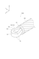
- FIG. 1 is an explanatory diagram illustrating a schematic configuration of a guide wire according to a first embodiment.
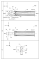
- FIG. 1 is an explanatory diagram showing a detailed configuration of a core wire constituting a guide wire in a first embodiment.
- FIG. 1 is an explanatory diagram showing a detailed configuration of a core wire constituting a guide wire in a first embodiment.
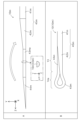
- FIG. 1 is an explanatory diagram showing an example of a method for producing a core wire in the first embodiment;
- FIG. 1 is an explanatory diagram showing an example of a method of using the guidewire in the first embodiment.
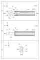
- FIG. 13 is an explanatory diagram showing a detailed configuration of a core wire constituting the guide wire of the second embodiment.
- FIG. 11 is an explanatory diagram showing an example of a method for producing a core wire constituting the guide wire of the second embodiment.
- FIG. 13 is an explanatory diagram showing a detailed configuration of a core wire constituting the guide wire of the third embodiment.
- FIG. 13 is an explanatory diagram showing a detailed configuration of a core wire constituting the guide wire of the fourth embodiment.
- FIG. 13 is an explanatory diagram showing an example of a method for producing a core wire constituting the guide wire of the fourth embodiment.
- FIG. 13 is an explanatory diagram showing a detailed configuration of a core wire constituting a guide wire in a fifth embodiment.
- FIG. 13 is an explanatory diagram showing a detailed configuration of a core wire constituting a guide wire in a sixth embodiment.
- FIG. 1 is an explanatory diagram that shows a schematic configuration of a guidewire 100 in the first embodiment.
- FIG. 1 shows the configuration of a side surface (side surface as viewed in the X-axis direction) of the guidewire 100.
- the positive Z-axis direction side is the tip end side (distal side) that is inserted into the body
- the negative Z-axis direction side is the base end side (proximal side) that is operated by an operator such as a doctor.
- a part of the guidewire 100 is omitted.
- FIG. 1 shows a state in which the central axis AX of the guidewire 100 is linear and parallel to the Z-axis direction.
- the guidewire 100 has flexibility to such an extent that it can be curved.
- the distal end of the guidewire 100 and each of its constituent members is referred to as the "tip”, the distal end and its vicinity are referred to as the “tip portion”, the proximal end is referred to as the "proximal end”, and the proximal end and its vicinity are referred to as the "proximal portion”.
- the outer diameter of the guidewire 100 and each of its constituent members means either the size or width along a direction perpendicular to the central axis AX.
- the longitudinal cross section of the guidewire 100 and each of its constituent members means a cross section that includes the central axis AX of the guidewire 100, and the transverse cross section of the guidewire 100 and each of its constituent members means a cross section perpendicular to the central axis AX.
- the guidewire 100 is a long medical device that is inserted into a blood vessel to treat a lesion (a narrowed or blocked area) in the blood vessel.
- the total length of the guidewire 100 is, for example, about 1500 mm to 2000 mm.
- the guidewire 100 comprises a core wire 10 and a coil body 20.
- the core wire 10 is an elongated member extending along the central axis AX of the guide wire 100, and is made of a metal wire.
- the core wire 10 has a large diameter portion 11, a small diameter portion 13 located at the distal end of the large diameter portion 11 and having a smaller diameter than the large diameter portion 11, a tapered portion 12 located between the large diameter portion 11 and the small diameter portion 13 and gradually decreasing in diameter from the boundary with the large diameter portion 11 toward the boundary with the small diameter portion 13, and a protruding portion 14 located at the distal end of the small diameter portion 13.
- the shape of the cross section (XY cross section) of the core wire 10 at each position can be any shape.
- the shape of the cross section of the core wire 10 at each position is circular or rectangular.
- the outer diameter of the large diameter portion 11 is, for example, about 0.2 mm to 0.8 mm. The configuration of the core wire 10 will be described in more detail later.
- the portion of the guidewire 100 excluding the protruding portion 14 of the core wire 10 is also referred to as the main body 102.
- the guidewire 100 has a long main body 102 and a protruding portion 14 that protrudes further toward the tip side than the tip of the main body 102.
- Most of the main body 102 has a circular cross section over its entire length, so the outer diameter can be measured at each axial position.
- the core wire 10 may be made of, for example, stainless steel (SUS302, SUS304, SUS316, etc.), Ni-Ti alloy, piano wire, etc.
- the entire core wire 10 may be made of the same material, or different parts may be made of different materials.
- the coil body 20 is a hollow cylindrical coil-shaped member in which one or more wires are wound around the outer circumference of the core wire 10.
- Each wire constituting the coil body 20 may be composed of a single strand, or may be a twisted wire in which multiple strands are twisted together.
- the coil body 20 is composed of a multi-strand coil in which multiple wires are wound, and each wire constituting the coil body 20 is a twisted wire.
- the coil body 20 covers almost the entire thin-diameter portion 13 of the core wire 10.
- the outer diameter of the coil body 20 is, for example, about 0.3 mm to 1.0 mm.
- the coil body 20 may have a constant outer diameter over its entire length, or may be tapered so that the outer diameter becomes smaller toward the tip.
- the coil body 20 may be made of a material that is transparent to radiation, such as stainless steel (SUS302, SUS304, SUS316, etc.), Ni-Ti alloy, or piano wire, or a material that is opaque to radiation, such as platinum, gold, tungsten, or an alloy of these.
- the coil body 20 may be made entirely of the same material, or different parts may be made of different materials.
- the materials for forming the tip-side joint 31, base-side joint 33, and intermediate joint 32 may be the same or different from each other.
- the distal joint 31, the proximal joint 33, and the intermediate joint 32 may be entirely made of the same material, or each part may be made of a different material.
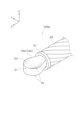
- FIG. 2 and 3 are explanatory diagrams showing a detailed configuration of the core wire 10 constituting the guide wire 100 in the first embodiment.
- FIG. 2 the configuration of the tip portion of the guide wire 100 is shown in an enlarged manner.
- column A of FIG. 3 the configuration of one partial longitudinal section (YZ longitudinal section) of the tip portion of the guide wire 100 is shown
- column B of FIG. 3 the configuration of another partial longitudinal section (XZ longitudinal section) of the tip portion of the guide wire 100 is shown
- column C of FIG. 3 the configuration of the transverse section (XY transverse section) of the protruding portion 14 of the core wire 10 at the position C-C in column A of FIG. 3 is shown.
- the protruding portion 14 is not shown as a cross section.
- the outer circumferential line of the protruding portion 14 shown in column A of FIG. 3 indicates the outline of the protruding portion 14 when viewed in the X-axis direction (i.e., when viewed in the first direction).
- the outer circumferential line of the protruding portion 14 shown in column B of FIG. 3 indicates the outline of the protruding portion 14 when viewed in the Y-axis direction (i.e., when viewed in the second direction).
- the contour as viewed in the X-axis direction is also referred to as a first contour
- the contour as viewed in the Y-axis direction is also referred to as a second contour.
- the protruding portion 14 of the core wire 10 is located on the tip side of the thin-diameter portion 13 covered by the coil body 20, and is a portion that protrudes further toward the tip side than the tip 21 of the coil body 20.
- the length of the protruding portion 14 along the direction of the central axis AX is, for example, approximately 0.5 mm to 2.0 mm.
- the base end of the protruding portion 14 is covered by the tip-side joint portion 31. The remaining portion of the protruding portion 14 is exposed to the outside.
- the protrusion 14 of the core wire 10 has a loop portion surrounding the through hole 15 extending in the X-axis direction. More specifically, the protrusion 14 has a configuration in which a wire having a substantially rectangular cross section (an intermediate portion 43m of the metal wire 10m described later) is bent into a loop around the X-axis and closed at the base end position. Therefore, as shown in column A of FIG. 3, the first contour of the protrusion 14 has a shape in which the outer periphery line has a curved portion. In this embodiment, substantially the entire outer periphery line in the first contour of the protrusion 14 is substantially arc-shaped. In the first contour of the protrusion 14, the inner periphery line that defines the through hole 15 also has a curved portion. In this embodiment, substantially the entire inner periphery line in the first contour of the protrusion 14 is substantially arc-shaped.
- the width W1 at the first central axis position P1 which is approximately near the center of the protrusion 14 along the central axis AX, is larger than the width W2 at the second central axis position P2, which is closer to the base end than the first central axis position P1.
- the width W1 at the first central axis position P1 is larger than the width W3 at the third central axis position P3, which is closer to the tip end than the first central axis position P1.
- the first contour of the protrusion 14 has a width Wp that is approximately the same as that of the thin-diameter portion 13 of the core wire 10 at the base end, and gradually increases in width from the base end toward the tip end, reaching a maximum width at the first central axis position P1, and gradually decreases in width from the first central axis position P1 toward the tip end.
- the first central axis position P1 is located closer to the tip end than the center along the central axis AX of the protrusion 14.
- the maximum width Wm1 of the protrusion 14 is, for example, about 0.2 mm to 1.0 mm.
- the surface visible when viewing the protrusion 14 from the positive direction of the X-axis is referred to as the upper surface S3, and the surface visible when viewing the protrusion 14 from the negative direction of the X-axis is referred to as the lower surface S4.
- the upper surface S3 and the lower surface S4 of the protrusion 14 are approximately flat, and the upper surface S3 and the lower surface S4 are approximately parallel to each other.
- the width (which can also be expressed as the thickness of the protrusion 14) at the second contour of the protrusion 14 is a substantially constant value Wm2.
- the protrusion 14 has a flattened shape in which the width is not constant at each position around the central axis AX.
- the surface of the protrusion 14 has an edge 16.
- the edge 16 is the boundary (ridge) between two surfaces.
- the surface of the protrusion 14 has an edge 16 that is the boundary between the outer peripheral surface S1 (the surface that constitutes the outer peripheral line of the first contour) and the upper surface S3, an edge 16 that is the boundary between the outer peripheral surface S1 and the lower surface S4, an edge 16 that is the boundary between the inner peripheral surface S2 (the surface that constitutes the inner peripheral line of the first contour) and the upper surface S3, and an edge 16 that is the boundary between the inner peripheral surface S2 and the lower surface S4.
- the edge 16 that is the boundary between the outer peripheral surface S1 and the upper surface S3 and the edge 16 that is the boundary between the outer peripheral surface S1 and the lower surface S4 are located on the first contour when viewed in the X-axis direction.
- the X-axis direction is an example of the first direction in the claims.
- the Y-axis direction is an example of the second direction in the claims.
- FIG. 4 is an explanatory diagram showing an example of a method for manufacturing the core wire 10 in the first embodiment.
- a metal wire 10m which is a material for forming the core wire 10 is manufactured.
- Section A of FIG. 4 shows a part of the distal end of the metal wire 10m, more specifically, a part of the thin-diameter portion 13 of the core wire 10 and a part that becomes the protruding portion 14. As shown in section A of FIG.
- the distal end part of the metal wire 10m has a first base end 41m, a second base end 42m, an intermediate portion 43m, and a distal end 44m.
- the first base end 41m and the second base end 42m are also collectively referred to as a base end 45m.
- the first base end 41m is a rod-shaped part having a substantially constant diameter.
- the second base end 42m is a portion extending from the tip of the first base end 41m in the tip direction, and has a tapered shape with a diameter gradually decreasing toward the tip. That is, the second base end 42m has a cross section with a smaller area than the cross section of the first base end 41m.
- the intermediate portion 43m is a portion extending from the tip of the second base end 42m in the tip direction, and is a rod-shaped portion having a substantially constant diameter (substantially the same diameter as the diameter of the tip of the second base end 42m). As shown in column A of FIG. 4, the cross section of the intermediate portion 43m is substantially rectangular.
- the tip portion 44m is a portion extending from the tip of the intermediate portion 43m to the tip of the metal wire 10m, and has a tapered shape with a diameter gradually decreasing toward the tip.
- the tapered shape of the second base end 42m and the tapered shape of the tip portion 44m are set to match each other, and the length of the second base end 42m and the length of the tip portion 44m are substantially the same.
- the metal wire 10m having such a shape can be produced, for example, by preparing a wire having a substantially uniform cross-sectional shape and polishing the wire.
- the first base end 41m is an example of a first portion in the claims, and the second base end 42m is an example of a second portion in the claims.
- the metal wire 10m is bent so that the tapered surface of the tip 44m abuts against the tapered surface of the second base end 42m, and the intermediate portion 43m is looped.
- the intermediate portion 43m becomes the loop portion of the protruding portion 14 of the core wire 10
- the mutually abutting tip portion 44m and the second base end 42m become rod-shaped with a substantially constant outer diameter, and together with the first base end 41m, constitute the thin-diameter portion 13 of the core wire 10.
- the above manufacturing method results in a core wire 10 having the protruding portion 14, the thin-diameter portion 13, the tapered portion 12, and the thick-diameter portion 11.
- the core wire 10 thus produced is inserted into the hollow portion of a coil body 20 prepared separately.
- the protrusion 14 of the core wire 10 is set in a state in which it protrudes further toward the distal end than the tip 21 of the coil body 20.
- a distal joint 31, an intermediate joint 32, and a proximal joint 33 are formed to join the coil body 20 and the core wire 10.
- the distal joint 31 joins the distal end 44m and the second proximal end 42m of the metal wire 10m constituting the core wire 10 to each other at a position covered by the coil body 20.
- a guide wire 100 having the above-mentioned configuration can be manufactured by the above-mentioned method.
- How to use the guidewire 100: 5 is an explanatory diagram showing an example of a method of using the guidewire 100 in the first embodiment.
- a technician such as a doctor inserts the guiding catheter 110 into a blood vessel 200 and advances the guiding catheter 110 until the tip of the guiding catheter 110 reaches the position of a lesion 220 (e.g., chronic total occlusion).
- the technician inserts the guidewire 100 into the hollow portion of the guiding catheter 110 and advances the guidewire 100 toward the lesion 220 in the blood vessel 200.
- the technician advances the guidewire 100 further toward the distal side while rotating the guidewire 100 around the central axis AX (clockwise in this embodiment). In this way, by advancing the guidewire 100 while rotating it around the central axis AX, even if the protrusion 14 of the core wire 10 located at the tip of the guidewire 100 touches the inner wall of the blood vessel 200, damage to the inner wall of the blood vessel 200 can be prevented.
- the operator continues to rotate the guidewire 100 around the central axis AX while advancing the guidewire 100 further distally.
- This causes the protrusion 14 of the core wire 10 to enter the lesion 220, and the protrusion 14 cuts through the lesion 220 by rotating around the central axis AX within the lesion 220.
- the coil body 20, which has a helical outer circumferential surface, also enters the lesion 220, and is screwed distally through the lesion 220 by rotating around the central axis AX within the lesion 220.
- the tip of the guidewire 100 reliably advances distally through the lesion 220, and finally penetrates the lesion 220.
- the catheter (not shown) is advanced to the position of the lesion 220, using the guidewire 100 that has penetrated the lesion 220 as a rail.
- the guidewire 100 When removing the guidewire 100, the guidewire 100 is retracted while rotating it about the central axis AX in the opposite direction to that at the time of insertion (counterclockwise in this embodiment). This allows the guidewire 100 to be smoothly retracted by the rotation of the coil body 20 having a helical outer peripheral surface, and prevents the inner wall of the blood vessel 200 from being damaged even if the protruding portion 14 of the core wire 10 located at the tip of the guidewire 100 touches the inner wall of the blood vessel 200.
- the guidewire 100 of the first embodiment has an elongated main body 102 and a protruding portion 14 that protrudes distally beyond the tip of the main body 102.
- the maximum width Wm1 of the first contour as viewed in the X-axis direction perpendicular to the central axis AX of the main body 102 is larger than the maximum width Wm2 of the second contour as viewed in the Y-axis direction perpendicular to the central axis AX.
- the first contour has a curved portion, and the width W1 of the first contour at the first central axis position P1 is larger than the width W2 of the first contour at the second central axis position P2 that is proximal to the first central axis position P1.
- the protrusion 14 has a shape in which the first contour has a curved portion when viewed in the X-axis direction.
- the maximum value of the width of the first contour of the protrusion 14 when viewed in the X-axis direction is greater than the maximum value of the width of the second contour when viewed in the Y-axis direction.
- the protrusion 14 has a rotationally asymmetric shape. Therefore, when the guidewire 100 is rotated around the central axis AX while the protrusion 14 is positioned at the lesion 220, the curved portion of the contour of the protrusion 14 can efficiently perforate the lesion 220. From the above, according to the guidewire 100 of this embodiment, it is possible to improve the penetration performance, and thereby improve the treatment efficiency of the guidewire 100.
- the X-axis direction which is the line of sight corresponding to the first contour
- the Y-axis direction which is the line of sight corresponding to the second contour.
- the protrusion 14 has a flat shape. Therefore, according to the guidewire 100 of this embodiment, it is possible to reduce resistance when the protrusion 14 enters the lesion 220 or when the protrusion 14 advances distally within the lesion 220, and the penetration performance of the guidewire 100 can be effectively improved.
- the maximum width W1 of the first contour of the protrusion 14 is equal to the maximum width Wm1 of the protrusion 14.
- the direction in which the first contour of the protrusion 14 has a curved portion coincides with the direction in which the protrusion 14 has the maximum width Wm1. Therefore, according to the guidewire 100 of this embodiment, the width of the portion of the protrusion 14 that corresponds to the curved portion can be maximized, effectively improving the perforation performance of the lesion 220 due to the rotation of the protrusion 14, and as a result, the penetration performance of the guidewire 100 can be further effectively improved.
- the surface of the protrusion 14 has an edge 16 that is the boundary between the two surfaces. Therefore, according to the guidewire 100 of this embodiment, by rotating the protrusion 14 around the central axis AX, the edge 16 on the surface of the protrusion 14 can cut through the lesion 220 to perforate it, and as a result, the penetration performance of the guidewire 100 can be further effectively improved.
- the surface of the protrusion 14 has an edge 16 on the first contour as viewed in the X-axis direction.
- the edge 16 can be positioned at the outermost position of the rotation trajectory when the protrusion 14 is rotated around the central axis AX, and the edge 16 of the rotating protrusion 14 can be reliably brought into contact with the lesion 220, and the perforation performance of the lesion 220 due to the rotation of the protrusion 14 can be effectively improved, and as a result, the penetration performance of the guidewire 100 can be extremely effectively improved.
- the width W1 of the first contour at the first central axis position P1 of the protrusion 14 is greater than the width W3 of the first contour at the third central axis position P3, which is closer to the tip side than the first central axis position P1.
- the main body 102 includes the core wire 10 made of a metal wire and a coil body 20 having one or more wires wound around the core wire 10 and joined to the core wire 10.
- the main body 102 since the main body 102 includes the core wire 10 and the coil body 20, when the guidewire 100 is rotated around the central axis AX, the coil body 20 also rotates around the central axis AX, and the protrusion 14 can be reliably advanced distally within the lesion 220 by the screwing action of the coil body 20 having a helical outer peripheral surface, and the penetration performance of the guidewire 100 can be further effectively improved.
- the protrusion 14 has a loop portion. Therefore, according to the guidewire 100 of this embodiment, the shape of the protrusion 14 can be made to have a relatively wide portion and a relatively thin linear portion, and the rotating protrusion 14 can effectively pierce the lesion 220, thereby extremely effectively improving the penetration performance of the guidewire 100.
- the protrusion 14 has a loop portion
- the metal wire 10m constituting the core wire 10 has a tip portion 44m, a base portion 45m, and an intermediate portion 43m located between the tip portion 44m and the base portion 45m.
- the tip portion 44m and the base portion 45m of the metal wire 10m are joined to each other at a position covered by the coil body 20.
- the intermediate portion 43m of the metal wire 10m constitutes a loop portion in the protrusion 14 of the core wire 10.
- the core wire 10 having the loop-shaped protrusion 14 can be formed using a single metal wire 10m, and as a result, detachment of the protrusion 14 can be suppressed compared to a configuration in which the protrusion 14 is formed as a separate body.
- the base end 45m of the metal wire 10m has a first base end 41m and a second base end 42m.
- the second base end 42m is adjacent to the first base end 41m on the tip side.
- the second base end 42m has a cross section smaller in area than the cross section of the first base end 41m and is joined to the tip end 44m of the metal wire 10m.
- the width of the part (a part of the tip side of the thin diameter section 13) formed by joining the second base end 42m and the tip end 44m of the metal wire 10m in the core wire 10 becomes excessively large, and it is possible to prevent the rigidity gap with the part formed by the first base end 41m (the remaining part of the thin diameter section 13) from becoming excessively large. Therefore, according to the guidewire 100 of this embodiment, the rigidity gap of the core wire 10 can be reduced, and the durability and operability of the guidewire 100 can be improved.
- the second base end 42m of the metal wire 10m constituting the core wire 10 has a tapered shape in which the width gradually decreases from the boundary position with the first base end 41m toward the tip side. Therefore, according to the guidewire 100 of this embodiment, compared to a configuration in which a step is provided at the boundary position between the second base end 42m and the first base end 41m, it is possible to prevent the rigidity gap of the metal wire 10m itself constituting the core wire 10 from becoming excessively large, and the durability and operability of the guidewire 100 can be effectively improved.
- the coil body 20 is composed of a multi-strand coil in which multiple wires are wound around the outer circumference of the core wire 10.
- a multi-strand coil has superior torque transmission and flexibility compared to a single-strand coil. Therefore, according to the guidewire 100 of this embodiment, the torque transmission and flexibility of the tip portion of the guidewire 100 can be effectively improved.
- FIG. 6 is an explanatory diagram showing a detailed configuration of the core wire 10 constituting the guide wire 100a of the second embodiment.
- section A of FIG. 6 the configuration of one partial longitudinal section (YZ longitudinal section) of the distal end of the guide wire 100a is shown
- section B of FIG. 6 the configuration of another partial longitudinal section (XZ longitudinal section) of the distal end of the guide wire 100a is shown
- section C of FIG. 6 the configuration of the transverse section (XY transverse section) of the protruding portion 14a of the core wire 10 at the position C-C in section A of FIG. 6 is shown.
- the protruding portion 14a is not shown as a cross section.
- the outer circumferential line of the protruding portion 14a shown in section A of FIG. 6 indicates the first contour of the protruding portion 14a when viewed in the X-axis direction (i.e., when viewed in the first direction).
- the outer circumferential line of the protruding portion 14a shown in section B of FIG. 6 indicates the second contour of the protruding portion 14a when viewed in the Y-axis direction (i.e., when viewed in the second direction).
- the core wire 10 constituting the guidewire 100a of the second embodiment differs from that of the first embodiment in the shape of the protrusion 14a.
- the protrusion 14a in the second embodiment has a configuration in which a wire (an intermediate portion 43m of the metal wire 10m described below) having a substantially semicircular cross section rather than a substantially rectangular cross section is bent into a loop around the X axis and closed at the base end.
- the straight portion in the substantially semicircular cross section of the wire constituting the protrusion 14a faces the through hole 15, and the arc portion in the substantially semicircular cross section faces the outer periphery.
- the other configuration of the protrusion 14a in the second embodiment is the same as that of the first embodiment.
- FIG. 7 is an explanatory diagram showing an example of a method for producing the core wire 10 constituting the guide wire 100a of the second embodiment.
- a metal wire 10m having a first base end 41m, a second base end 42m, an intermediate portion 43m, and a tip end 44m is produced, as in the first embodiment.
- the cross section of the intermediate portion 43m is made to be approximately semicircular rather than approximately rectangular.
- the metal wire 10m is bent so as to be folded back, so that the tapered surface of the tip end 44m abuts against the tapered surface of the second base end 42m, and the intermediate portion 43m is looped.
- the intermediate portion 43m becomes the loop portion of the protruding portion 14a of the core wire 10.
- the guidewire 100a of the second embodiment has a configuration similar to that of the guidewire 100 of the first embodiment, and therefore provides the same effects as those provided by the guidewire 100 of the first embodiment described above (such as improved penetration performance).
- FIG. 8 is an explanatory diagram showing a detailed configuration of the core wire 10 constituting the guide wire 100b of the third embodiment.
- column A of FIG. 8 the configuration of one partial longitudinal section (YZ longitudinal section) of the distal end of the guide wire 100b is shown
- column B of FIG. 8 the configuration of another partial longitudinal section (XZ longitudinal section) of the distal end of the guide wire 100b is shown
- column C of FIG. 8 the configuration of the transverse section (XY transverse section) of the protruding portion 14b of the core wire 10 at the position C-C in column A of FIG. 8 is shown.
- columns A and B of FIG. 8 the protruding portion 14b is not shown as a cross section.
- the outer circumferential line of the protruding portion 14b shown in column A of FIG. 8 indicates the first contour of the protruding portion 14b when viewed in the X-axis direction (i.e., when viewed in the first direction).
- the outer circumferential line of the protruding portion 14b shown in column B of FIG. 8 indicates the second contour of the protruding portion 14b when viewed in the Y-axis direction (i.e., when viewed in the second direction).
- the core wire 10 constituting the guidewire 100b of the third embodiment differs from that of the second embodiment in the shape of the protrusion 14b.
- the protrusion 14b in the third embodiment has a configuration in which a wire having a substantially semicircular cross section is bent into a loop shape around the X-axis, similar to the protrusion 14a in the second embodiment.
- the arc-shaped portion of the substantially semicircular cross section of the wire constituting the protrusion 14b faces the through-hole 15, and the straight portion of the substantially semicircular cross section faces the outer periphery.
- the other configuration of the protrusion 14b in the third embodiment is the same as that of the second embodiment.
- a metal wire 10m having a first base end 41m, a second base end 42m, an intermediate portion 43m, and a tip end 44m is produced in the same manner as in the second embodiment (see FIG. 7).
- the cross section of the intermediate portion 43m is made to be approximately semicircular rather than approximately rectangular.
- the straight portion in the approximately semicircular cross section of the portion (intermediate portion 43m) that constitutes the protrusion 14b in the metal wire 10m faces the outer periphery.
- the guidewire 100b of the third embodiment has a similar configuration to the guidewire 100a of the second embodiment, and therefore has the same effects (such as improved penetration performance) as the guidewire 100a of the second embodiment described above.
- the surface of the protrusion 14b has an edge 16 on the first contour as viewed in the X-axis direction.
- the edge 16 can be arranged at the outermost position of the rotation trajectory when the protrusion 14b is rotated around the central axis AX, and the edge 16 of the rotating protrusion 14b can be reliably brought into contact with the lesion 220, effectively improving the perforation performance of the lesion 220 due to the rotation of the protrusion 14b.
- the penetration performance of the guidewire 100b can be extremely effectively improved.
- FIG. 9 is an explanatory diagram showing a detailed configuration of the core wire 10 constituting the guide wire 100c of the fourth embodiment.
- column A of FIG. 9 the configuration of one partial longitudinal section (YZ longitudinal section) of the distal end of the guide wire 100c is shown
- column B of FIG. 9 the configuration of another partial longitudinal section (XZ longitudinal section) of the distal end of the guide wire 100c is shown
- column C of FIG. 9 the configuration of the transverse section (XY transverse section) of the protruding portion 14c of the core wire 10 at the position C-C in column A of FIG. 9 is shown.
- columns A and B of FIG. 9 the protruding portion 14c is not shown as a cross section.
- the outer circumferential line of the protruding portion 14c shown in column A of FIG. 9 indicates the first contour of the protruding portion 14c when viewed in the X-axis direction (i.e., when viewed in the first direction).
- the outer circumferential line of the protruding portion 14c shown in column B of FIG. 9 indicates the second contour of the protruding portion 14c when viewed in the Y-axis direction (i.e., when viewed in the second direction).
- the guide wire 100c of the fourth embodiment differs from the second embodiment in the configuration of the metal wire 10m constituting the core wire 10.
- FIG. 10 is an explanatory diagram showing an example of a method for manufacturing the core wire 10 constituting the guide wire 100c of the fourth embodiment.
- a metal wire 10m having a first base end 41m, a second base end 42m, an intermediate portion 43m, and a tip portion 44m is manufactured.
- a step is provided at the boundary position between the first base end 41m and the second base end 42m, so that the cross-sectional area of the second base end 42m is made smaller than the cross-sectional area of the first base end 41m.
- the second base end 42m is a rod-shaped portion having an approximately constant diameter, and its cross-sectional shape is approximately the same as the cross-sectional shape of the intermediate portion 43m. As shown in columns A and B of FIG. 10, by bending the metal wire 10m having such a configuration, the outer circumferential surface of the tip 44m abuts against the outer circumferential surface of the second base end 42m, and the intermediate portion 43m is looped.
- the intermediate portion 43m becomes the loop portion of the protruding portion 14c of the core wire 10
- the tip portion 44m and the second base end 42m that abut against each other become rod-shaped with a substantially constant outer diameter, and together with the first base end 41m, form the thin-diameter portion 13 of the core wire 10.
- the guidewire 100c of the fourth embodiment has a similar configuration to the guidewire 100a of the second embodiment, and therefore provides the same effects (such as improved penetration performance) as those provided by the guidewire 100a of the second embodiment described above.
- Fig. 11 is an explanatory diagram showing a detailed configuration of the core wire 10 constituting the guidewire 100d in the fifth embodiment.
- Fig. 11 shows an enlarged configuration of the distal end portion of the guidewire 100d.
- the same configurations as those of the guidewire 100 in the first embodiment described above are denoted by the same reference numerals and the description thereof will be omitted as appropriate.
- the core wire 10 constituting the guidewire 100d of the fifth embodiment differs from that of the first embodiment in the shape of the protrusion 14d.
- the protrusion 14d in the fifth embodiment is paddle-shaped rather than having a loop. That is, the protrusion 14d in the fifth embodiment has a configuration in which the through-hole 15 in the protrusion 14 in the first embodiment is filled. Therefore, the YZ vertical section and the XZ vertical section of the protrusion 14d in the fifth embodiment have the same shapes as the YZ vertical section and the XZ vertical section of the protrusion 14 in the first embodiment, except that there is no through-hole 15.
- the protrusion 14d of such a shape can be produced, for example, by performing pressing or polishing on a wire material.
- the guidewire 100d of the fifth embodiment has a similar configuration to the guidewire 100 of the first embodiment, and therefore provides the same effects (such as improved penetration performance) as those provided by the guidewire 100 of the first embodiment described above.
- Fig. 12 is an explanatory diagram showing a detailed configuration of the core wire 10 constituting the guidewire 100e in the sixth embodiment.
- Fig. 12 shows an enlarged configuration of the distal end portion of the guidewire 100e.
- the same configurations as those of the guidewire 100 of the first embodiment described above are denoted by the same reference numerals and the description thereof will be omitted as appropriate.
- the core wire 10 constituting the guidewire 100e of the sixth embodiment differs from that of the first embodiment in the shape of the protrusion 14e.
- the protrusion 14e in the sixth embodiment is spoon-shaped rather than having a loop. That is, the protrusion 14e in the sixth embodiment has a configuration in which the through hole 15 in the protrusion 14 in the first embodiment is filled and a recess is formed on the upper surface S3. Therefore, the YZ vertical section and the XZ vertical section of the protrusion 14e in the sixth embodiment have the same shapes as the YZ vertical section and the XZ vertical section of the protrusion 14 in the first embodiment, except that a recess exists instead of the through hole 15. Note that the protrusion 14e of such a shape can be produced, for example, by performing pressing or polishing on a wire material.
- the guidewire 100e of the sixth embodiment has a configuration similar to that of the guidewire 100 of the first embodiment, and therefore provides the same effects (such as improved penetration performance) as those provided by the guidewire 100 of the first embodiment described above.
- the coil body 20 is configured as a multi-strand coil in which multiple wires are wound, and each wire that constitutes the coil body 20 is a twisted wire.
- Each wire that constitutes the coil body 20 may be a single strand rather than a twisted wire.
- the coil body 20 may be a single-strand coil in which a single wire is wound, rather than a multi-strand coil.
- the coil body 20 may be a densely wound coil or a loosely wound coil.
- the core wire 10 has a thick portion 11, a tapered portion 12, and a thin portion 13.
- the core wire 10 may not have at least one of these three portions, or may have other portions in addition to the three portions.
- the shape and size of the protrusion 14 are merely examples, and other shapes and sizes may be used as long as the first contour of the protrusion 14 has a curved portion when viewed in the first direction, and the width of the first contour at the first central axis position is greater than the width of the first contour at the second central axis position proximal to the first central axis position.
- the protrusion 14 may be prepared separately and brazed to the thin-diameter portion 13.
- At least one of the distal joint 31, the intermediate joint 32, and the proximal joint 33 may be omitted.
- At least a portion of the guidewire 100 may be coated with, for example, a resin.
- each component in the above embodiment is merely examples and can be modified in various ways.
- the manufacturing method of the guidewire 100 in the above embodiment is merely examples and can be modified in various ways.
- the guidewire 100 for treating a lesion in a blood vessel has been used as an example.
- the technology disclosed in this specification is similarly applicable to medical devices for treating body cavities (blood vessels, digestive tract, ureter, etc.).
Landscapes
- Health & Medical Sciences (AREA)
- Life Sciences & Earth Sciences (AREA)
- Surgery (AREA)
- Veterinary Medicine (AREA)
- Public Health (AREA)
- General Health & Medical Sciences (AREA)
- Engineering & Computer Science (AREA)
- Biomedical Technology (AREA)
- Heart & Thoracic Surgery (AREA)
- Animal Behavior & Ethology (AREA)
- Molecular Biology (AREA)
- Medical Informatics (AREA)
- Nuclear Medicine, Radiotherapy & Molecular Imaging (AREA)
- Vascular Medicine (AREA)
- Biophysics (AREA)
- Pulmonology (AREA)
- Anesthesiology (AREA)
- Hematology (AREA)
- Orthopedic Medicine & Surgery (AREA)
- Media Introduction/Drainage Providing Device (AREA)
Priority Applications (10)
| Application Number | Priority Date | Filing Date | Title |
|---|---|---|---|
| EP23927415.2A EP4681765A1 (en) | 2023-03-14 | 2023-03-14 | Medical device |
| JP2025506329A JPWO2024189794A1 (https=) | 2023-03-14 | 2023-03-14 | |
| CN202380094902.3A CN120752071A (zh) | 2023-03-14 | 2023-03-14 | 医疗设备 |
| PCT/JP2023/009924 WO2024189794A1 (ja) | 2023-03-14 | 2023-03-14 | 医療デバイス |
| EP24770966.0A EP4512455A4 (en) | 2023-03-14 | 2024-03-14 | MEDICAL DEVICE, METHOD FOR MANUFACTURING A MEDICAL DEVICE AND METHOD OF TREATMENT |
| PCT/JP2024/009976 WO2024190863A1 (ja) | 2023-03-14 | 2024-03-14 | 医療デバイス、医療デバイスの製造方法、治療方法 |
| JP2025506927A JPWO2024190863A5 (ja) | 2024-03-14 | 医療デバイス | |
| CN202480015093.7A CN120882447A (zh) | 2023-03-14 | 2024-03-14 | 医疗设备、医疗设备的制造方法、治疗方法 |
| US19/307,687 US20250387600A1 (en) | 2023-03-14 | 2025-08-22 | Medical device and method of manufacturing the same, and method of treatment |
| US19/307,797 US20250387601A1 (en) | 2023-03-14 | 2025-08-22 | Medical device |
Applications Claiming Priority (1)
| Application Number | Priority Date | Filing Date | Title |
|---|---|---|---|
| PCT/JP2023/009924 WO2024189794A1 (ja) | 2023-03-14 | 2023-03-14 | 医療デバイス |
Related Child Applications (1)
| Application Number | Title | Priority Date | Filing Date |
|---|---|---|---|
| US19/307,797 Continuation US20250387601A1 (en) | 2023-03-14 | 2025-08-22 | Medical device |
Publications (1)
| Publication Number | Publication Date |
|---|---|
| WO2024189794A1 true WO2024189794A1 (ja) | 2024-09-19 |
Family
ID=92754734
Family Applications (2)
| Application Number | Title | Priority Date | Filing Date |
|---|---|---|---|
| PCT/JP2023/009924 Ceased WO2024189794A1 (ja) | 2023-03-14 | 2023-03-14 | 医療デバイス |
| PCT/JP2024/009976 Ceased WO2024190863A1 (ja) | 2023-03-14 | 2024-03-14 | 医療デバイス、医療デバイスの製造方法、治療方法 |
Family Applications After (1)
| Application Number | Title | Priority Date | Filing Date |
|---|---|---|---|
| PCT/JP2024/009976 Ceased WO2024190863A1 (ja) | 2023-03-14 | 2024-03-14 | 医療デバイス、医療デバイスの製造方法、治療方法 |
Country Status (5)
| Country | Link |
|---|---|
| US (2) | US20250387601A1 (https=) |
| EP (2) | EP4681765A1 (https=) |
| JP (1) | JPWO2024189794A1 (https=) |
| CN (2) | CN120752071A (https=) |
| WO (2) | WO2024189794A1 (https=) |
Citations (5)
| Publication number | Priority date | Publication date | Assignee | Title |
|---|---|---|---|---|
| JP2007530130A (ja) * | 2004-03-26 | 2007-11-01 | ブリヴァント リサーチ アンド ディベロップメント リミテッド | ヒト又は動物被験者における血管閉塞部位の再開通に用いるためのガイドワイヤー |
| US20090093829A1 (en) * | 2007-10-09 | 2009-04-09 | Cook Incorporated | Chronic total occlusion (CTO) removal device |
| US20090264907A1 (en) * | 2008-04-18 | 2009-10-22 | Boston Scientific Scimed, Inc. | Medical device for crossing an occluded blood vessel |
| US20180280052A1 (en) | 2017-03-31 | 2018-10-04 | Jihad A. Mustapha | Chronic total occlusion crossing devices and methods |
| JP2019209152A (ja) | 2018-06-08 | 2019-12-12 | ニューラヴィ・リミテッド | 血管内医療システムで使用するための非外傷性血塊回避構成遠位端を有するガイドワイヤ |
Family Cites Families (4)
| Publication number | Priority date | Publication date | Assignee | Title |
|---|---|---|---|---|
| EP2627279B1 (en) * | 2010-10-14 | 2023-11-01 | Corindus Inc. | Occlusion traversal robotic catheter system |
| JP5979792B2 (ja) * | 2013-04-16 | 2016-08-31 | 朝日インテック株式会社 | ガイドワイヤ |
| JP2020039377A (ja) | 2017-01-23 | 2020-03-19 | テルモ株式会社 | ガイドワイヤ |
| ES3009676T3 (en) * | 2018-08-24 | 2025-03-31 | Neuravi Ltd | Apparatus for managing acute ischemic events |
-
2023
- 2023-03-14 WO PCT/JP2023/009924 patent/WO2024189794A1/ja not_active Ceased
- 2023-03-14 CN CN202380094902.3A patent/CN120752071A/zh active Pending
- 2023-03-14 EP EP23927415.2A patent/EP4681765A1/en active Pending
- 2023-03-14 JP JP2025506329A patent/JPWO2024189794A1/ja active Pending
-
2024
- 2024-03-14 EP EP24770966.0A patent/EP4512455A4/en active Pending
- 2024-03-14 WO PCT/JP2024/009976 patent/WO2024190863A1/ja not_active Ceased
- 2024-03-14 CN CN202480015093.7A patent/CN120882447A/zh active Pending
-
2025
- 2025-08-22 US US19/307,797 patent/US20250387601A1/en active Pending
- 2025-08-22 US US19/307,687 patent/US20250387600A1/en active Pending
Patent Citations (8)
| Publication number | Priority date | Publication date | Assignee | Title |
|---|---|---|---|---|
| JP2007530130A (ja) * | 2004-03-26 | 2007-11-01 | ブリヴァント リサーチ アンド ディベロップメント リミテッド | ヒト又は動物被験者における血管閉塞部位の再開通に用いるためのガイドワイヤー |
| US20090093829A1 (en) * | 2007-10-09 | 2009-04-09 | Cook Incorporated | Chronic total occlusion (CTO) removal device |
| US20090264907A1 (en) * | 2008-04-18 | 2009-10-22 | Boston Scientific Scimed, Inc. | Medical device for crossing an occluded blood vessel |
| US20180280052A1 (en) | 2017-03-31 | 2018-10-04 | Jihad A. Mustapha | Chronic total occlusion crossing devices and methods |
| US20180280051A1 (en) | 2017-03-31 | 2018-10-04 | Jihad A. Mustapha | Chronic total occlusion crossing devices and methods |
| WO2018184017A1 (en) | 2017-03-31 | 2018-10-04 | Mustapha Jihad A | Chronic total occlusion crossing devices and methods |
| US20210121199A1 (en) | 2017-03-31 | 2021-04-29 | Jihad A. Mustapha | Chronic total occlusion crossing devices and methods |
| JP2019209152A (ja) | 2018-06-08 | 2019-12-12 | ニューラヴィ・リミテッド | 血管内医療システムで使用するための非外傷性血塊回避構成遠位端を有するガイドワイヤ |
Non-Patent Citations (1)
| Title |
|---|
| See also references of EP4681765A1 |
Also Published As
| Publication number | Publication date |
|---|---|
| CN120882447A (zh) | 2025-10-31 |
| WO2024190863A1 (ja) | 2024-09-19 |
| EP4512455A1 (en) | 2025-02-26 |
| US20250387600A1 (en) | 2025-12-25 |
| JPWO2024189794A1 (https=) | 2024-09-19 |
| EP4512455A4 (en) | 2025-10-15 |
| CN120752071A (zh) | 2025-10-03 |
| EP4681765A1 (en) | 2026-01-21 |
| JPWO2024190863A1 (https=) | 2024-09-19 |
| US20250387601A1 (en) | 2025-12-25 |
Similar Documents
| Publication | Publication Date | Title |
|---|---|---|
| JP2008155052A (ja) | 医療用ガイドワイヤ | |
| US20210299412A1 (en) | Guide Wires | |
| US20230121231A1 (en) | Guide Wires | |
| EP4427789B1 (en) | Guide wire | |
| WO2024189794A1 (ja) | 医療デバイス | |
| JP2013176488A (ja) | ガイドワイヤ | |
| US20230181879A1 (en) | Guide wire | |
| CN111840755A (zh) | 一种介入治疗用导丝 | |
| US12589227B2 (en) | Guide wires | |
| JP7732824B2 (ja) | ガイドワイヤ | |
| JP2013208351A (ja) | ガイドワイヤ | |
| JP2025140255A (ja) | ガイドワイヤ | |
| JP2026055189A (ja) | 医療デバイス | |
| JP2025101070A (ja) | ガイドワイヤ | |
| JP2026055190A (ja) | 医療デバイスの製造方法、および、医療デバイス | |
| JP2025183999A (ja) | 医療デバイス | |
| US20260076691A1 (en) | Medical device and method for manufacturing medical device | |
| JP2026055188A (ja) | 医療デバイス、及び医療デバイスの製造方法 | |
| US20260076700A1 (en) | Medical device | |
| US20260076690A1 (en) | Medical device | |
| JP7364369B2 (ja) | ガイドワイヤ | |
| JP6994287B2 (ja) | ガイドワイヤ | |
| JP2025175317A (ja) | 医療デバイスおよび医療デバイスの製造方法 | |
| WO2025142505A1 (ja) | ガイドワイヤ | |
| JP2021132753A (ja) | ガイドワイヤ |
Legal Events
| Date | Code | Title | Description |
|---|---|---|---|
| 121 | Ep: the epo has been informed by wipo that ep was designated in this application |
Ref document number: 23927415 Country of ref document: EP Kind code of ref document: A1 |
|
| ENP | Entry into the national phase |
Ref document number: 2025506329 Country of ref document: JP Kind code of ref document: A |
|
| WWE | Wipo information: entry into national phase |
Ref document number: 2025506329 Country of ref document: JP |
|
| WWE | Wipo information: entry into national phase |
Ref document number: CN2023800949023 Country of ref document: CN Ref document number: 202380094902.3 Country of ref document: CN |
|
| WWP | Wipo information: published in national office |
Ref document number: 202380094902.3 Country of ref document: CN |
|
| WWE | Wipo information: entry into national phase |
Ref document number: 2023927415 Country of ref document: EP |
|
| NENP | Non-entry into the national phase |
Ref country code: DE |
|
| ENP | Entry into the national phase |
Ref document number: 2023927415 Country of ref document: EP Effective date: 20251014 |
|
| ENP | Entry into the national phase |
Ref document number: 2023927415 Country of ref document: EP Effective date: 20251014 |
|
| ENP | Entry into the national phase |
Ref document number: 2023927415 Country of ref document: EP Effective date: 20251014 |
|
| ENP | Entry into the national phase |
Ref document number: 2023927415 Country of ref document: EP Effective date: 20251014 |
|
| ENP | Entry into the national phase |
Ref document number: 2023927415 Country of ref document: EP Effective date: 20251014 |