WO2024189671A1 - 通信システム - Google Patents
通信システム Download PDFInfo
- Publication number
- WO2024189671A1 WO2024189671A1 PCT/JP2023/009294 JP2023009294W WO2024189671A1 WO 2024189671 A1 WO2024189671 A1 WO 2024189671A1 JP 2023009294 W JP2023009294 W JP 2023009294W WO 2024189671 A1 WO2024189671 A1 WO 2024189671A1
- Authority
- WO
- WIPO (PCT)
- Prior art keywords
- power supply
- unit
- optical
- communication
- supply light
- Prior art date
- Legal status (The legal status is an assumption and is not a legal conclusion. Google has not performed a legal analysis and makes no representation as to the accuracy of the status listed.)
- Ceased
Links
Images


Classifications
-
- H—ELECTRICITY
- H04—ELECTRIC COMMUNICATION TECHNIQUE
- H04B—TRANSMISSION
- H04B10/00—Transmission systems employing electromagnetic waves other than radio-waves, e.g. infrared, visible or ultraviolet light, or employing corpuscular radiation, e.g. quantum communication
- H04B10/80—Optical aspects relating to the use of optical transmission for specific applications, not provided for in groups H04B10/03 - H04B10/70, e.g. optical power feeding or optical transmission through water
Definitions
- the present invention relates to a communication system.
- FIG 4 is a configuration diagram of a conventional communication system powered by optical power supply (see, for example, non-patent document 1).
- the communication system comprises an optical line terminal (OLT), a power supply light source, and an optical network unit (ONU).
- OLT optical line terminal
- ONU optical network unit
- the ONU is connected to both the OLT and the power supply light source by optical fiber.
- the ONU transmits and receives optical signals to and from the OLT to perform data communication, and is powered by optical power supply from the power supply light source.
- the present invention aims to provide a communication system that can provide optical power supply to communication devices with improved safety.
- a communication system includes a plurality of power supply light sources and a first communication device.
- the first communication device includes a communication unit that communicates with a second communication device, a first multiplexing unit that multiplexes power supply light of different wavelengths output from each of the plurality of power supply light sources, and a photoelectric conversion unit that converts the power supply light multiplexed by the first multiplexing unit into electricity and supplies the converted electricity to the communication unit.
- the present invention makes it possible to provide optical power supply to communication devices with improved safety.
- FIG. 1 is a configuration diagram of a communication system according to a first embodiment of the present invention.
- FIG. 11 is a configuration diagram of a communication system according to a second embodiment.
- FIG. 11 is a configuration diagram of a communication system according to a third embodiment.
- FIG. 1 is a configuration diagram of a conventional communication system.
- the communication system of this embodiment bundles multiple light beams from low-output light sources to supply power to a communication device. This ensures the power required for the operation of the communication device while ensuring safety.
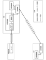
- FIG. 1 is a configuration diagram of a communication system 1 in a first embodiment of the present invention.
- the communication system 1 includes a plurality of power supply light sources 2, an OLT (Optical Line Terminal) 3, and an ONU (Optical Network Unit) 4.
- the power supply light sources 2 and the ONU 4 are connected by an optical fiber 5, and the OLT 3 and the ONU 4 are connected by an optical fiber 6.
- the ONU 4 is an example of a first communication device
- the OLT 3 is an example of a second communication device
- the optical fibers 5 and 6 are examples of optical transmission paths.
- FIG. 1 shows an example in which there are three power supply light sources 2. These power supply light sources 2 are described as power supply light sources 2a, 2b, and 2c, respectively.
- the number of power supply light sources 2 is not limited to three, and may be two or more.
- the power supply light source 2 includes a laser 21.
- the laser 21 of each power supply light source 2 outputs light of a wavelength different from the wavelength of light output by the laser 21 of the other power supply light sources 2.
- the power supply light source 2 inputs the light output by the laser 21 into the optical fiber 5 as power supply light.
- the OLT 3 comprises a communication function unit 31 and a transmission/reception unit 32.
- the communication function unit 31 generates data signals to be sent to the ONU 4, and receives data signals received from the ONU 4.
- the transmission/reception unit 32 converts the data signals generated by the communication function unit 31 and addressed to the ONU 4 from electrical signals to optical signals and outputs them to the optical fiber 6.
- the transmission/reception unit 32 also receives optical signals output from the ONU 4 and transmitted through the optical fiber 6, converts the received optical signals into electrical data signals, and outputs them to the communication function unit 31.
- the ONU 4 includes a WDM (Wavelength Division Multiplex) coupler 41, an opto-electrical conversion unit 42, a transceiver unit 43, and a communication function unit 44.
- the WDM coupler 41 is an example of a first multiplexing unit
- the transceiver unit 43 and the communication function unit 44 are examples of a communication unit.
- the WDM coupler 41 combines the power supply light of different wavelengths transmitted through each optical fiber 5, and outputs the combined power supply light to the photoelectric conversion unit 42.
- the photoelectric conversion unit 42 includes a photodiode 421 and a power supply unit 422.
- the photodiode 421 converts the power supply light combined by the WDM coupler 41 into electricity.
- the power supply unit 422 is, for example, a secondary battery.
- the power supply unit 422 stores the electricity converted by the photodiode 421, and supplies the stored electricity to each unit such as the transmission/reception unit 43 and the communication function unit 44.
- the transmitter/receiver 43 and the communication function unit 44 operate on power supplied from the power supply unit 422.
- the transmitter/receiver 43 receives an optical signal output from the OLT 3 and transmitted through the optical fiber 6, converts the received optical signal into an electrical data signal, and outputs it to the communication function unit 44.
- the transmitter/receiver 43 also converts a data signal generated by the communication function unit 44 and addressed to the OLT 3 from an electrical signal into an optical signal, and outputs it to the optical fiber 6.
- the communication function unit 44 performs a receiving process for the data signal converted into an electrical signal by the transmitter/receiver 43.
- the communication function unit 44 also performs a generating process for a data signal, and outputs the generated data signal addressed to the OLT 3 to the transmitter/receiver 43.
- the laser 21 of the power supply light source 2a outputs power supply light of wavelength A to the optical fiber 5a
- the laser 21 of the power supply light source 2b outputs power supply light of wavelength B to the optical fiber 5b
- the laser 21 of the power supply light source 2c outputs power supply light of wavelength C to the optical fiber 5c.
- the WDM coupler 41 of the ONU 4 multiplexes the power supply light of wavelength A transmitted through the optical fiber 5a, the power supply light of wavelength B transmitted through the optical fiber 5b, and the power supply light of wavelength C transmitted through the optical fiber 5c, and outputs the multiplexed power supply light to the photoelectric conversion unit 42.
- the photodiode 421 of the photoelectric conversion unit 42 converts the power supply light multiplexed by the WDM coupler 41 into electric power.
- the power supply unit 422 supplies the electric power converted by the photodiode 421 to the transmission/reception unit 43 and the communication function unit 44.
- the communication function unit 31 of the OLT 3 and the communication function unit 44 of the ONU 4 perform data communication via the transmission/reception unit 32 and the transmission/reception unit 43. That is, the transmission/reception unit 32 of the OLT 3 converts the electrical signal for data communication generated by the communication function unit 31 into an optical signal and outputs it to the optical fiber 6.
- the transmission/reception unit 43 of the ONU 4 receives the optical signal transmitted through the optical fiber 6, converts it into an electrical signal, and outputs it to the communication function unit 44.
- the transmission/reception unit 43 of the ONU 4 also converts the electrical signal for data communication generated by the communication function unit 44 into an optical signal and outputs it to the optical fiber 6.
- the transmission/reception unit 32 of the OLT 3 receives the optical signal transmitted through the optical fiber 6, converts it into an electrical signal, and outputs it to the communication function unit 31.
- the first and second communication devices are ONU 4 and OLT 3, and the first and second communication devices perform data communication using optical signals.
- the present invention can also be applied to cases where the first and second communication devices perform data communication using electrical signals, wireless signals, etc.
- the transceiver 43 and the transceiver 32 transmit and receive electrical signals, wireless signals, etc.
- the power supply light and the optical signal for data communication are transmitted through different optical fibers.
- the optical signal for data communication is transmitted through the same fiber as the power supply light. The second embodiment will be described focusing on the difference from the first embodiment.
- FIG. 2 is a configuration diagram of a communication system 11 of the second embodiment.
- the communication system 11 of the second embodiment shown in FIG. 2 differs from the communication system 1 of the first embodiment shown in FIG. 1 in that it does not have an optical fiber 6, the power supply light source 2c and the OLT 3 are connected to the optical fiber 5c via a WDM coupler 71, and the WDM coupler 41 and the transceiver 43 of the ONU 4 are connected to the optical fiber 5c via a WDM coupler 72.
- the WDM coupler 71 is an example of a second multiplexing section
- the WDM coupler 72 is an example of a demultiplexing section.
- the laser 21 of the power supply light source 2a outputs power supply light of wavelength A
- the laser 21 of the power supply light source 2b outputs power supply light of wavelength B
- the laser 21 of the power supply light source 2c outputs power supply light of wavelength C
- the transceiver unit 32 of the OLT 3 outputs an optical signal for data communication addressed to the ONU 4.
- the wavelength P of the output optical signal is different from the wavelength C of the power supply light.
- the WDM coupler 71 outputs a superimposed signal obtained by multiplexing the power supply light output from the power supply light source 2c and the optical signal output from the OLT 3 to the optical fiber 5c.
- the WDM coupler 72 separates the superimposed signal transmitted through the optical fiber 5c by wavelength.
- the WDM coupler 72 outputs the power supply light of wavelength C to the WDM coupler 41 and outputs the optical signal of wavelength P to the transceiver unit 43.
- the WDM coupler 41 of the ONU 4 combines the power supply light of wavelength A transmitted through the optical fiber 5a, the power supply light of wavelength B transmitted through the optical fiber 5b, and the power supply light of wavelength C output from the WDM coupler 72.
- the photodiode 421 converts the power supply light combined by the WDM coupler 41 into electric power.
- the power supply unit 422 supplies the electric power converted by the photodiode 421 to the transceiver unit 43 and the communication function unit 44.
- the transceiver unit 43 converts the optical signal of wavelength P output from the WDM coupler 72 into an electric signal and outputs it to the communication function unit 44.
- the transmitter/receiver 43 of the ONU 4 converts the electrical signal for data communication generated by the communication function unit 44 into an optical signal and outputs the converted optical signal.
- the WDM coupler 72 outputs the optical signal output from the transmitter/receiver 43 to the optical fiber 5c.
- the WDM coupler 71 outputs the optical signal output by the ONU 4 and transmitted through the optical fiber 5c to the OLT 3.
- the transmitter/receiver 32 of the OLT 3 converts the optical signal output from the WDM coupler 71 into an electrical signal and outputs it to the communication function unit 31.
- the ONU has one WDM coupler.
- the ONU has two WDM couplers, one of which multiplexes a plurality of feed light beams as in the first and second embodiments, and the other WDM coupler demultiplexes the feed light beam and the optical signal for data communication transmitted through the same optical fiber.
- the third embodiment will be described focusing on the differences from the first and second embodiments.
- FIG. 3 is a configuration diagram of a communication system 12 of the third embodiment.
- the communication system 12 of the third embodiment shown in FIG. 3 differs from the communication system 1 of the first embodiment shown in FIG. 1 in that it has an ONU 40 instead of an ONU 4, does not have an optical fiber 6, and the power supply light source 2c and the OLT 3 are connected to an optical fiber 5c via a WDM coupler 71.
- the ONU 40 differs from the ONU 4 shown in FIG. 1 in that it further includes a WDM coupler 45.
- the WDM coupler 45 is an example of a demultiplexing unit.
- the WDM coupler 45 demultiplexes the superimposed signal transmitted through the optical fiber 5c into a power supply light and an optical signal, outputs the power supply light to the WDM coupler 41, and outputs the optical signal to the transceiver unit 43.
- the WDM coupler 45 also outputs the optical signal output by the transceiver unit 43 to the optical fiber 5c.
- the operation of the communication system 12 will be described.
- the laser 21 of the power supply light source 2a outputs power supply light of wavelength A
- the laser 21 of the power supply light source 2b outputs power supply light of wavelength B
- the laser 21 of the power supply light source 2c outputs power supply light of wavelength C.
- the transceiver unit 32 of the OLT 3 outputs an optical signal for data communication addressed to the ONU 40.
- the WDM coupler 71 outputs a superimposed signal obtained by multiplexing the power supply light of wavelength C output from the power supply light source 2c and the optical signal of wavelength P output from the OLT 3 to the optical fiber 5c.
- the WDM coupler 45 of the ONU 40 splits the superimposed signal transmitted through the optical fiber 5c by wavelength.
- the WDM coupler 72 outputs the power supply light of wavelength C to the WDM coupler 41 and outputs the optical signal of wavelength P to the transceiver 43.
- the WDM coupler 41 of the ONU 40 multiplexes the power supply light of wavelength A transmitted through the optical fiber 5a, the power supply light of wavelength B transmitted through the optical fiber 5b, and the power supply light of wavelength C output from the WDM coupler 45.
- the photodiode 421 converts the power supply light multiplexed by the WDM coupler 41 into electric power.
- the power supply unit 422 supplies the electric power converted by the photodiode 421 to the transceiver 43 and the communication function unit 44.
- the transceiver 43 converts the optical signal of wavelength P output from the WDM coupler 45 into an electric signal and outputs it to the communication function unit 44.
- a safe, low-output light source can be used for optical power supply.
- power can be supplied from multiple light sources, it is possible to operate communication devices that consume a lot of power.
- the communication system includes a plurality of power supply light sources and a first communication device.
- the first communication device corresponds, for example, to the ONUs 4 and 40 in the embodiment.
- the first communication device includes a communication unit, a first multiplexing unit, and an opto-electrical conversion unit.
- the communication unit communicates with the second communication device.
- the communication unit corresponds to the transceiver unit 43 and the communication function unit 44 in the embodiment
- the second communication device corresponds to the OLT 3 in the embodiment.
- the first multiplexing unit multiplexes power supply light of different wavelengths output from each of the plurality of power supply light sources.
- the first multiplexing unit corresponds to the WDM coupler 41 in the embodiment.
- the opto-electrical conversion unit converts the power supply light multiplexed by the first multiplexing unit into electric power and supplies the converted electric power to the communication unit.
- the first multiplexer may receive the power supply light output from each of the multiple power supply light sources from multiple different optical transmission paths.
- the optical transmission path corresponds to, for example, the optical fiber 5 in the embodiment.
- the communication unit may transmit and receive optical signals between the second communication device via an optical transmission path different from the multiple optical transmission paths through which the power supply light is transmitted.
- the optical transmission path through which the optical signal is transmitted corresponds to, for example, the optical fiber 6 in the embodiment.
- the communication unit may transmit and/or receive optical signals between the second communication device and the second communication device via any one of the multiple optical transmission paths.
- the superimposed signal optical transmission path which is an optical transmission path through which an optical signal is transmitted among the multiple optical transmission paths, may have a second multiplexing section and a demultiplexing section.
- the second multiplexing section corresponds to the WDM coupler 71 of the embodiment
- the demultiplexing section corresponds to the WDM coupler 72 of the embodiment
- the superimposed signal optical transmission path corresponds to the optical fiber 5c of the embodiment.
- the second multiplexing section outputs a superimposed signal obtained by multiplexing the power supply light output from any of the power supply light sources and the optical signal output from the second communication device to the superimposed signal optical transmission path.
- the demultiplexing section separates the superimposed signal transmitted through the superimposed signal optical transmission path into the power supply light and the optical signal and outputs them to the first communication device. Furthermore, the demultiplexing section may output the optical signal output by the first communication device to the superimposed signal optical transmission path, and the second multiplexing section may output the signal output by the demultiplexing section to the superimposed signal optical transmission path to the second communication device.
- the optical transmission path for the superimposed signal which is an optical transmission path among the multiple optical transmission paths through which the optical signal is transmitted, may include a second multiplexing section.
- the second multiplexing section corresponds to the WDM coupler 71 of the embodiment
- the optical transmission path for the superimposed signal corresponds to the optical fiber 5c of the embodiment.
- the second multiplexing section outputs a superimposed signal obtained by multiplexing the power supply light output from any of the power supply light sources and the optical signal output from the second communication device to the optical transmission path for the superimposed signal.
- the first communication device also includes a demultiplexing section.
- the demultiplexing section corresponds to, for example, the WDM coupler 45 of the embodiment.
- the demultiplexing section separates the superimposed signal transmitted through the optical transmission path for the superimposed signal into power supply light and an optical signal, outputs the separated power supply light to the first multiplexing section, and outputs the separated optical signal to the communication section. Furthermore, the demultiplexing unit may output the optical signal output by the communication unit to the optical transmission path for the superimposed signal, and the second multiplexing unit may output the optical signal output by the demultiplexing unit to the optical transmission path for the superimposed signal to the second communication device.
Landscapes
- Physics & Mathematics (AREA)
- Electromagnetism (AREA)
- Engineering & Computer Science (AREA)
- Computer Networks & Wireless Communication (AREA)
- Signal Processing (AREA)
- Optical Communication System (AREA)
Priority Applications (2)
| Application Number | Priority Date | Filing Date | Title |
|---|---|---|---|
| JP2025506231A JPWO2024189671A1 (https=) | 2023-03-10 | 2023-03-10 | |
| PCT/JP2023/009294 WO2024189671A1 (ja) | 2023-03-10 | 2023-03-10 | 通信システム |
Applications Claiming Priority (1)
| Application Number | Priority Date | Filing Date | Title |
|---|---|---|---|
| PCT/JP2023/009294 WO2024189671A1 (ja) | 2023-03-10 | 2023-03-10 | 通信システム |
Publications (1)
| Publication Number | Publication Date |
|---|---|
| WO2024189671A1 true WO2024189671A1 (ja) | 2024-09-19 |
Family
ID=92754561
Family Applications (1)
| Application Number | Title | Priority Date | Filing Date |
|---|---|---|---|
| PCT/JP2023/009294 Ceased WO2024189671A1 (ja) | 2023-03-10 | 2023-03-10 | 通信システム |
Country Status (2)
| Country | Link |
|---|---|
| JP (1) | JPWO2024189671A1 (https=) |
| WO (1) | WO2024189671A1 (https=) |
Citations (4)
| Publication number | Priority date | Publication date | Assignee | Title |
|---|---|---|---|---|
| JP2005198396A (ja) * | 2004-01-06 | 2005-07-21 | Kansai Electric Power Co Inc:The | 光給電システム |
| JP2008193327A (ja) * | 2007-02-02 | 2008-08-21 | Kansai Electric Power Co Inc:The | 光給電情報伝送装置 |
| WO2011158283A1 (ja) * | 2010-06-14 | 2011-12-22 | 富士通テレコムネットワークス株式会社 | 光伝送システム |
| WO2022176185A1 (ja) * | 2021-02-22 | 2022-08-25 | 株式会社京都セミコンダクター | 光給電コンバータ |
-
2023
- 2023-03-10 JP JP2025506231A patent/JPWO2024189671A1/ja active Pending
- 2023-03-10 WO PCT/JP2023/009294 patent/WO2024189671A1/ja not_active Ceased
Patent Citations (4)
| Publication number | Priority date | Publication date | Assignee | Title |
|---|---|---|---|---|
| JP2005198396A (ja) * | 2004-01-06 | 2005-07-21 | Kansai Electric Power Co Inc:The | 光給電システム |
| JP2008193327A (ja) * | 2007-02-02 | 2008-08-21 | Kansai Electric Power Co Inc:The | 光給電情報伝送装置 |
| WO2011158283A1 (ja) * | 2010-06-14 | 2011-12-22 | 富士通テレコムネットワークス株式会社 | 光伝送システム |
| WO2022176185A1 (ja) * | 2021-02-22 | 2022-08-25 | 株式会社京都セミコンダクター | 光給電コンバータ |
Also Published As
| Publication number | Publication date |
|---|---|
| JPWO2024189671A1 (https=) | 2024-09-19 |
Similar Documents
| Publication | Publication Date | Title |
|---|---|---|
| KR100975881B1 (ko) | 외부 씨드 광원을 이용한 파장 분할 다중화 수동형광가입자망(wdm-pon) | |
| US8260135B2 (en) | Passive optical network system and wavelength assignment method | |
| KR100875922B1 (ko) | Wdm 수동형 광가입자망에서의 파장 무의존 광원을이용한 하향 광송신 장치 및 그 방법과, 그를 이용한광선로 종단 시스템 | |
| US8543001B2 (en) | Cascaded injection locking of fabry-perot laser for wave division multiplexing passive optical networks | |
| EP2819325B1 (en) | Distributed base-station signal transmission system and communication system | |
| US8055133B2 (en) | TDM/WDMA passive optical network device | |
| US8249453B2 (en) | Optical communication system | |
| US20100021164A1 (en) | Wdm pon rf/video broadcast overlay | |
| WO2010093195A9 (ko) | 저잡음 다파장 광원을 구비한 저잡음 광신호의 전송 장치, 저잡음 다파장 광원을 이용한 방송 신호 전송 장치, 및 이를 구비한 광가입자망 | |
| WO2011130995A1 (zh) | 光码分多址无源光网络系统、光分配网装置及光线路终端 | |
| CN101981834A (zh) | 用于多个波分复用的无源光网络(wdm-pon)的受保护光源 | |
| US9287987B2 (en) | Self-seeded colorless burst-mode transmitter using reflective semiconductor optical amplifier and injection locked Fabry-Perot laser | |
| CN101238654B (zh) | 波分复用无源光网络系统 | |
| US11294258B2 (en) | Transmission device and transmission system | |
| KR100990780B1 (ko) | 파장 분할 다중화 방식의 수동형 광 가입자망 시스템 | |
| US20070183778A1 (en) | Passive optical network | |
| JP7399673B2 (ja) | 光ファイバー給電システム | |
| WO2024189671A1 (ja) | 通信システム | |
| US7756419B2 (en) | Traffic signal node cross scheduling method and system | |
| RU2009114694A (ru) | Устройство и способ для терминала оптической линии (olt) и модуля оптической сети (onu) в независимых от длины волны пассивных оптических сетях с мультиплексированием с разделением по длине волны | |
| Feng et al. | Large-capacity optical access network utilizing multicore fiber and self-homodyne coherent detection | |
| US20120163818A1 (en) | Passive optical network apparatus for transmitting optical signal | |
| EP2503712B1 (en) | Hybrid electrical/optical splitting oeo pon | |
| KR20060134644A (ko) | 인터리버를 구비한 파장분할다중 방식의 수동형 광가입자망 | |
| US7352967B1 (en) | Data transmission system |
Legal Events
| Date | Code | Title | Description |
|---|---|---|---|
| 121 | Ep: the epo has been informed by wipo that ep was designated in this application |
Ref document number: 23927295 Country of ref document: EP Kind code of ref document: A1 |
|
| ENP | Entry into the national phase |
Ref document number: 2025506231 Country of ref document: JP Kind code of ref document: A |
|
| WWE | Wipo information: entry into national phase |
Ref document number: 2025506231 Country of ref document: JP |
|
| NENP | Non-entry into the national phase |
Ref country code: DE |
|
| 122 | Ep: pct application non-entry in european phase |
Ref document number: 23927295 Country of ref document: EP Kind code of ref document: A1 |