WO2024185488A1 - 電磁継電器 - Google Patents
電磁継電器 Download PDFInfo
- Publication number
- WO2024185488A1 WO2024185488A1 PCT/JP2024/006044 JP2024006044W WO2024185488A1 WO 2024185488 A1 WO2024185488 A1 WO 2024185488A1 JP 2024006044 W JP2024006044 W JP 2024006044W WO 2024185488 A1 WO2024185488 A1 WO 2024185488A1
- Authority
- WO
- WIPO (PCT)
- Prior art keywords
- case
- conductive member
- restricting
- restricting portion
- terminal
- Prior art date
- Legal status (The legal status is an assumption and is not a legal conclusion. Google has not performed a legal analysis and makes no representation as to the accuracy of the status listed.)
- Ceased
Links
Images

Classifications
-
- H—ELECTRICITY
- H01—ELECTRIC ELEMENTS
- H01H—ELECTRIC SWITCHES; RELAYS; SELECTORS; EMERGENCY PROTECTIVE DEVICES
- H01H50/00—Details of electromagnetic relays
- H01H50/14—Terminal arrangements
-
- H—ELECTRICITY
- H01—ELECTRIC ELEMENTS
- H01H—ELECTRIC SWITCHES; RELAYS; SELECTORS; EMERGENCY PROTECTIVE DEVICES
- H01H50/00—Details of electromagnetic relays
- H01H50/02—Bases; Casings; Covers
-
- H—ELECTRICITY
- H01—ELECTRIC ELEMENTS
- H01H—ELECTRIC SWITCHES; RELAYS; SELECTORS; EMERGENCY PROTECTIVE DEVICES
- H01H50/00—Details of electromagnetic relays
- H01H50/54—Contact arrangements
- H01H50/546—Contact arrangements for contactors having bridging contacts
-
- H—ELECTRICITY
- H01—ELECTRIC ELEMENTS
- H01H—ELECTRIC SWITCHES; RELAYS; SELECTORS; EMERGENCY PROTECTIVE DEVICES
- H01H71/00—Details of the protective switches or relays covered by groups H01H73/00 - H01H83/00
- H01H71/02—Housings; Casings; Bases; Mountings
- H01H71/025—Constructional details of housings or casings not concerning the mounting or assembly of the different internal parts
- H01H71/0257—Strength considerations
Definitions
- the present invention relates to an electromagnetic relay.
- a conductive member is used as a current path to pass electricity from the contact device to an external device.
- the conductive member has a fixed portion that is connected to the fixed terminal of the contact device, and an extension portion that extends downward from the fixed portion to the side of the fixed terminal of the contact device.
- the extension of the conductive member is positioned to the side of the fixed terminal of the contact device.
- the Lorentz force causes the extension of the conductive member to move in a direction away from the side of the fixed terminal of the contact device, with the fixed terminal of the contact device as a fulcrum.
- This movement of the extension of the conductive member can deform the conductive member, which can cause the connection between the conductive member and the contact device to become unstable.
- the object of the present invention is to provide an electromagnetic relay that can stably maintain the connection between the conductive member and the contact device by suppressing deformation of the conductive member.
- An electromagnetic relay comprises a case, a drive device, a contact device, and a conductive member.
- the drive device is disposed inside the case.
- the contact device has a terminal portion. At least a portion of the terminal portion is disposed inside the case.
- the conductive member has a connection portion that connects to the tip of the terminal portion, and an extension portion that extends from the connection portion along the side of the terminal portion. At least one of the connection portion, the extension portion, and the case has a restricting portion. The restricting portion restricts deformation of the conductive member.
- the restricting portion can suppress deformation of the conductive member with the terminal portion of the contact device as a fulcrum. This makes it possible to stably maintain the connection state of the conductive member and the contact device.
- the terminal portion of the contact device may be disposed inside the case.
- the connection portion and extension portion of the conductive member are disposed inside the case.
- the restricting portion is provided on the inner surface of the case so as to be able to abut against at least one of the connection portion and the extension portion. It is preferable that the restricting portion is a protrusion that protrudes from the inner surface of the case.
- the terminal portion of the contact device may be disposed inside the case.
- the connection portion and extension portion of the conductive member are disposed inside the case.
- the restricting portion is provided on at least one of the connection portion and the extension portion so as to be able to abut against the case. It is preferable that the restricting portion is a protrusion that protrudes from at least one of the connection portion and the extension portion toward the inner surface of the case.
- connection portion and extension portion deformation of the conductive member (connection portion and extension portion) can be suppressed by providing a restricting portion.
- connection state of the conductive member and the contact device can be stably maintained with a simple configuration.
- the tip of the terminal portion of the contact device may be disposed outside the case.
- the connection portion and the extension portion of the conductive member are disposed outside the case.
- the restricting portion is provided on the outer surface of the case so as to be able to hold the extension portion. It is preferable that the restricting portion is a slit portion formed so as to be able to engage the extension portion.
- the terminal portion of the contact device may have a first terminal portion and a second terminal portion arranged at a distance from the first terminal portion.
- the conductive member has a first conductive member and a second conductive member.
- the first conductive member has a first connection portion and a first extension portion.
- the first connection portion is connected to the tip of the first terminal portion and extends in a first direction away from the first terminal portion.
- the first extension portion extends from the first connection portion along the side of the first terminal portion in a first intersecting direction that intersects with the first direction.
- the second conductive member has a second connection portion and a second extension portion.
- the second connection portion is connected to the tip of the second terminal portion and extends in a second direction away from the second terminal portion.
- the second extension portion extends from the second connection portion along the side of the second terminal portion in a second intersecting direction that intersects with the second direction.
- the restricting portion has a first restricting portion and a second restricting portion.
- the first restricting portion is provided on at least one of the first connecting portion, the first extending portion, and the case.
- the second restricting portion is provided on at least one of the second connecting portion, the second extending portion, and the case. Even with this configuration, the restricting portions (the first restricting portion and the second restricting portion) can suppress deformation of the conductive member, and the joined state of the conductive member and the contact device can be stably maintained.
- deformation of the conductive member in an electromagnetic relay can be suppressed, thereby making it possible to stably maintain the connection state between the conductive member and the contact device.
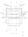
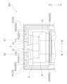
- FIG. FIG. FIG. 2 is a partially enlarged side view of the electromagnetic relay.
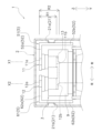
- FIG. 11 is a partially enlarged side view of an electromagnetic relay according to a first modified example.
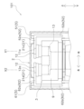
- FIG. 11 is a partially enlarged side view of an electromagnetic relay in a second modified example.
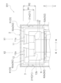
- FIG. 11 is a partially enlarged side view of an electromagnetic relay in a third modified example.
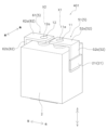
- FIG. 13 is a perspective view of an electromagnetic relay in a fourth modified example.
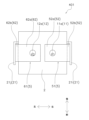
- FIG. 13 is a top view of an electromagnetic relay in a fourth modified example.
- the electromagnetic relay 1 includes a case 2, a contact device 3, a drive device 4, and a conductive member 5.
- the direction in which the contact device 3 and the drive device 4 are arranged side by side is defined as the upward direction.
- the opposite direction to the upward direction is defined as the downward direction.
- the direction in which the first fixed terminal 11 and the second fixed terminal 12, which will be described later, are arranged side by side is defined as the left-right direction.
- the direction perpendicular to the left-right direction and the up-down direction is defined as the front-rear direction.
- the case 2 is formed in a box shape.
- the case 2 is formed from an insulating material such as resin.
- a contact device 3 and a drive device 4 are arranged inside the case 2.
- the contact device 3 is arranged next to the drive device 4 inside the case 2.
- the contact device 3 is arranged above the drive device 4 inside the case 2.
- the case 2 has a restricting portion 21.
- the restricting portion 21 has a first restricting portion 21a and a second restricting portion 21b.
- the first restricting portion 21a restricts the deformation of the first conductive member 51.
- a force directed to the right from the central axis X1 of the first fixed terminal 11 acts on the first extension portion 52b (described later) of the first conductive member 51.
- the first restricting portion 21a restricts the deformation of the first extension portion 52b of the first conductive member 51.
- the first restricting portion 21a is provided on the inner surface of the case 2 so as to be able to abut against the first conductive member 51.
- the first restricting portion 21a is provided on the inner surface of the right side wall of the case 2 to the right of the upper end 11a of the first fixed terminal 11, for example, to the right of the central axis X1 of the first fixed terminal 11.
- the first restricting portion 21a is a protrusion that protrudes from the inner surface of the right side wall of the case 2.
- the first restricting portion 21a is integrally formed with the inner surface of the right side wall of the case 2.
- the first restricting portion 21a may be formed separately from the right side wall of the case 2. In this case, the first restricting portion 21a is attached to the inner surface of the right side wall of the case 2 as a separate member.
- the first restricting portion 21a is disposed on the inner surface of the right side wall of the case 2 so as to face the first extension portion 52b of the first conductive member 51 in the left-right direction.
- the first restricting portion 21a is disposed on the inner surface of the right side wall of the case 2 within a range R1 of the right side wall of the case 2 that faces the side surface of the first fixed terminal 11.
- the range R1 may be interpreted as corresponding to the distance between the upper surface of the first fixed terminal 11 and the lower surface of the first fixed terminal 11 in the vertical direction.
- the first restricting portion 21a may be disposed on the inner surface of the right side wall of the case 2 within range R2 of the right side wall of the case 2.
- Range R2 of the right side wall of the case 2 is a range that faces the side surface of the first fixed terminal 11 and the side surface of the movable contact piece 13 (described later) on the right side wall of the case 2.
- range R2 may be interpreted as corresponding to the vertical distance between the upper surface of the first fixed terminal 11 and the lower surface of the movable contact piece 13.
- the first restricting portion 21a is provided partially on the inner surface of the right side wall of the case 2 within the above range R1 or within the above range R2.
- the first restricting portion 21a may be provided on the inner surface of the right side wall of the case 2 throughout the entire ranges R1 and R2, as long as it is within the above range R1 or within the above range R2.
- the second restricting portion 21b restricts the deformation of the second conductive member 61.
- a force directed leftward from the central axis X2 of the second fixed terminal 12 acts on the second extension portion 62b (described later) of the second conductive member 61.
- the second restricting portion 21b restricts the deformation of the second extension portion 62b of the second conductive member 61.
- the configuration of the second restricting portion 21b is the same as that of the first restricting portion 21a, except for the arrangement of the second restricting portion 21b.
- the configuration of the second restricting portion 21b can be understood by replacing “first" with “second” and “right” with “left”. For this reason, in this embodiment, a detailed description of the second restricting portion 21b is omitted.
- the contact device 3 has a contact case 9, a first fixed terminal 11 (an example of a terminal portion; an example of a first terminal portion), a second fixed terminal 12 (an example of a terminal portion; an example of a second terminal portion), and a movable contact piece 13.
- the contact case 9 is disposed inside the case 2.
- the contact case 9 is disposed on the top of the drive unit 4.
- the contact case 9 has a first fixed terminal 11, a second fixed terminal 12, and a movable contact piece 13 disposed therein.
- the first and second fixed terminals 11, 12 are terminals for connecting an external circuit.
- the first and second fixed terminals 11, 12 are formed from a conductive material such as copper or a copper alloy.
- the conductive material may be a material other than copper or a copper alloy.
- the first and second fixed terminals 11, 12 are arranged at a distance from each other.
- the first and second fixed terminals 11, 12 are arranged at a distance in the left-right direction.
- the first and second fixed terminals 11, 12 are supported by the contact case 9.
- the first and second fixed terminals 11, 12 are formed in a substantially cylindrical shape.
- the first and second fixed terminals 11, 12 have central axes X1, X2. At least a portion of the first and second fixed terminals 11, 12 is disposed inside the case 2. Specifically, the upper ends 11a, 12a of the first and second fixed terminals 11, 12 protrude from the upper surface of the contact case 9.
- the upper end 11a of the first fixed terminal 11 is connected to a first conductive member 51, which will be described later.
- the lower end 11b of the first fixed terminal 11 is disposed inside the contact case 9.
- the upper end 12a of the second fixed terminal 12 is connected to a second conductive member 61, which will be described later.
- the lower end 12b of the second fixed terminal 12 is disposed inside the contact case 9.
- the movable contact piece 13 is a plate-shaped terminal that is long in one direction.
- the movable contact piece 13 is made of a conductive material such as copper or a copper alloy.
- the conductive material may be a material other than copper or a copper alloy.
- the movable contact piece 13 is disposed below the first and second fixed terminals 11, 12.
- the movable contact piece 13 is disposed below the first and second fixed terminals 11, 12, facing the first and second fixed terminals 11, 12.
- the drive unit 4 moves the movable contact piece 13.
- the drive unit 4 moves the movable contact piece 13 in the vertical direction.
- the drive unit 4 moves the movable contact piece 13 between a closed position CP where the movable contact piece 13 contacts the lower ends 11b, 12b of the first and second fixed terminals 11, 12, and an open position OP where the movable contact piece 13 is separated from the first and second fixed terminals 11, 12.
- the movable contact piece 13 located in the closed position CP is indicated by a dashed line
- the movable contact piece 13 located in the open position OP is indicated by a two-dot dashed line.
- the drive unit 4 is disposed inside the case 2.
- the drive unit 4 is disposed below the movable contact piece 13.
- the drive unit 4 has a coil 41 and a yoke 42.
- the coil 41 is disposed below the movable contact piece 13.
- the movable contact piece 13 By switching the state of voltage applied to the coil 41, the movable contact piece 13 is positioned in the open position OP or the closed position CP. For example, when no voltage is applied to the coil 41, the return mechanism (not shown) of the moving structure 43 positions the movable contact piece 13 in the open position OP. In this state, the first and second fixed terminals 11, 12 are not electrically connected.
- the configuration of the moving structure 43 (return structure and magnetic attraction structure) is the same as that of the conventional technology, so a detailed description of the configuration of the moving structure 43 (return structure and magnetic attraction structure) is omitted here.
- the yoke 42 is disposed between the coil 41 and the case 2.
- the yoke 42 is disposed so as to surround the coil 41.
- the yoke 42 has a bent C-shape.
- the yoke 42 is disposed so as to surround the lower surface of the coil 41, both side surfaces of the coil 41, and the upper surface of the yoke 42.
- the conductive member 5 is connected to the contact device 3 inside the case 2.
- the conductive member 5 has a first conductive member 51 and a second conductive member 61.
- the first and second conductive members 51, 61 are formed from a conductive material such as copper or a copper alloy.
- the conductive material may be a material other than copper or a copper alloy.
- the first and second conductive members 51, 61 are formed by bending a strip-shaped metal plate.
- the first conductive member 51 has a first current-carrying portion 52.
- the first current-carrying portion 52 is connected to the contact device 3 to form a current path.
- the first current-carrying portion 52 is connected to the first fixed terminal 11.
- the first current-carrying portion 52 has a first connection portion 52a (an example of a connection portion) and a first extension portion 52b (an example of an extension portion). A current-carrying path is formed by the first connection portion 52a and the first extension portion 52b.
- the first connection portion 52a is disposed on the inside of the case 2.
- the first connection portion 52a is disposed so as to face the upper wall of the case 2.
- the first connection portion 52a extends in a direction from the second fixed terminal 12 toward the first fixed terminal 11, for example, to the right (an example of a first direction) away from the first fixed terminal 11.
- the first extension 52b is disposed inside the case 2.
- the first extension 52b is disposed so as to face the right side wall of the case 2.
- the first extension 52b is disposed so as to face the first restricting portion 21a.
- the first extension portion 52b extends from the other end of the first connection portion 52a along the side of the first fixed terminal 11. For example, one end of the first extension portion 52b is connected to the other end of the first connection portion 52a.
- the first extension portion 52b extends downward (an example of the first intersecting direction) from the other end of the first connection portion 52a along the side of the first fixed terminal 11. In this state, the first extension portion 52b abuts against the first restriction portion 21a.
- a gap may be provided between the first extension portion 52b and the first restriction portion 21a.
- the second conductive member 61 has a second current-carrying portion 62.
- the second current-carrying portion 62 has a second connection portion 62a (an example of a connection portion) and a second extension portion 62b (an example of an extension portion).
- the configuration of the second conductive member 61 is substantially the same as the configuration of the first conductive member 51, except for the arrangement of the second conductive member 61.
- the configuration of the second conductive member 61 can be understood by replacing “first" with “second” and “right” with “left.”
- the second connection portion 62a extends in a direction from the first fixed terminal 11 toward the second fixed terminal 12, for example to the left away from the second fixed terminal 12 (an example of a second direction).
- the second extension portion 62b extends downward from the second connection portion 62a along the side of the second fixed terminal 12 (an example of a second intersecting direction).
- the first extension 52b of the first conductive member 51 abuts against the first restricting portion 21a of the case 2, thereby restricting deformation of the first conductive member 51 (first extension 52b).
- the second extension 62b of the second conductive member 61 abuts against the second restricting portion 21b of the case 2, thereby restricting deformation of the second conductive member 61 (second extension 62b).
- the electromagnetic relay 101 may be configured as shown in Variation 1 of FIG. 4.
- the restricting portion 21 is provided on the case 2 so as to be able to abut against the first and second connecting portions 52a, 62a.
- the restricting portion 21 has a third restricting portion 21c and a fourth restricting portion 21d.
- the third restricting portion 21c is provided on the inner surface of the case 2 so as to be able to abut against the first conductive member 51.
- the third restricting portion 21c is provided on the inner surface of the upper wall of the case 2 to the right of the upper end 11a of the first fixed terminal 11, for example, to the right of the central axis X1 of the first fixed terminal 11.
- the third restricting portion 21c is a protrusion that protrudes from the inner surface of the top wall of the case 2.
- the third restricting portion 21c is formed integrally with the inner surface of the top wall of the case 2.
- the third restricting portion 21c may be formed separately from the top wall of the case 2. In this case, the third restricting portion 21c is attached to the inner surface of the top wall of the case 2 as a separate member.
- the third restricting portion 21c is disposed on the inner surface of the upper wall of the case 2 so as to face the first conductive member 51 in the up-down direction.
- the third restricting portion 21c is disposed on the inner surface of the upper wall of the case 2 so as to face the first connection portion 52a of the first conductive member 51.
- the first connection portion 52a of the first conductive member 51 abuts against the third restricting portion 21c.
- a gap may be provided between the third restricting portion 21c and the first connection portion 52a.
- the third restricting portion 21c is partially provided on the inner surface of the upper wall of the case 2 to the right of the central axis X1 of the first fixed terminal 11.
- the third restricting portion 21c may be provided entirely on the inner surface of the upper wall of the case 2, as long as it is to the right of the central axis X1 of the first fixed terminal 11.
- the configuration of the fourth restricting portion 21d is the same as that of the third restricting portion 21c, except for the arrangement of the fourth restricting portion 21d.
- the configuration of the fourth restricting portion 21d can be understood by replacing “third” with “fourth” and “right” with “left”. For this reason, in this embodiment, a detailed description of the fourth restricting portion 21d is omitted.
- the first connection portion 52a of the first conductive member 51 abuts against the third restriction portion 21c of the case 2, thereby restricting deformation of the first conductive member 51 (first connection portion 52a).
- the second connection portion 62a of the second conductive member 61 abuts against the fourth restriction portion 21d of the case 2, thereby restricting deformation of the second conductive member 61 (second connection portion 62a).
- the third and fourth restricting portions 21c, 21d may be used in combination with the first and second restricting portions 21a, 21b of the above embodiment.
- the electromagnetic relay 201 may be configured as shown in Variation 2 of FIG. 5.
- the restricting portion 21 is provided on the conductive member 5.
- the restricting portion 21 is provided on the first and second extension portions 52b and 62b so as to be able to abut against the case 2.
- the restricting portion 21 has a fifth restricting portion 21e and a sixth restricting portion 21f.
- the fifth restricting portion 21e is a protruding portion that protrudes from the first extension portion 52b toward the inner surface of the right side wall of the case 2.
- the first restricting portion 21a is provided on the inner surface of the right side wall of the case 2 so as to face the first extension portion 52b.
- the fifth restricting portion 21e is provided on the first extension portion 52b so as to face the inner surface of the right side wall of the case 2. In this way, except for the fact that the fifth restricting portion 21e is attached to the first extension portion 52b, the configuration of the fifth restricting portion 21e is substantially the same as the first restricting portion 21a of the embodiment described above.
- the sixth restricting portion 21f is a protrusion that protrudes from the second extension portion 62b toward the inner surface of the left side wall of the case 2.
- the configuration of the sixth restricting portion 21f is substantially the same as that of the second restricting portion 21b of the above embodiment, except that the sixth restricting portion 21f is attached to the second extension portion 62b. Therefore, the detailed description of the fifth restricting portion 21e and the sixth restricting portion 21f is similar to the description of the first restricting portion 21a and the second restricting portion 21b of the above embodiment.
- the fifth restricting portion 21e of the first conductive member 51 (first extension portion 52b) abuts against the inner surface of the right side wall of the case 2, thereby restricting deformation of the first conductive member 51 (first extension portion 52b).
- the sixth restricting portion 21f of the second conductive member 61 (second extension portion 62b) abuts against the inner surface of the left side wall of the case 2, thereby restricting deformation of the second conductive member 61 (second extension portion 62b).
- the fifth and sixth restricting portions 21e, 21f may be used in combination with the third and fourth restricting portions 21c, 21d.
- the electromagnetic relay 301 may be configured as shown in Variation 3 of FIG. 6.
- the restricting portion 21 is provided on the conductive member 5.
- the restricting portion 21 is provided on the first and second connecting portions 52a, 62a so as to be able to abut against the case 2.
- the restricting portion 21 has a seventh restricting portion 21g and an eighth restricting portion 21h.
- the seventh restricting portion 21g is a protruding portion that protrudes from the first connecting portion 52a toward the inner surface of the upper wall of the case 2.
- the third restricting portion 21c is provided on the inner surface of the top surface of the case 2 so as to face the first connecting portion 52a.
- the seventh restricting portion 21g is provided on the first connecting portion 52a so as to face the inner surface of the top wall of the case 2. In this way, except for the fact that the seventh restricting portion 21g is attached to the first connecting portion 52a, the configuration of the seventh restricting portion 21g is substantially the same as the third restricting portion 21c of the above embodiment.
- the eighth restricting portion 21h is a protrusion that protrudes from the second connection portion 62a toward the inner surface of the upper wall of the case 2.
- the configuration of the eighth restricting portion 21h is substantially the same as that of the fourth restricting portion 21d of the above embodiment, except that the eighth restricting portion 21h is attached to the second connection portion 62a. Therefore, the detailed description of the seventh restricting portion 21g and the eighth restricting portion 21h is similar to the description of the third restricting portion 21c and the fourth restricting portion 21d of the above embodiment.
- the seventh restricting portion 21g of the first conductive member 51 (first connection portion 52a) abuts against the inner surface of the top wall of the case 2, thereby restricting deformation of the first conductive member 51 (first connection portion 52a).
- the eighth restricting portion 21h of the second conductive member 61 (second connection portion 62a) abuts against the inner surface of the top wall of the case 2, thereby restricting deformation of the second conductive member 61 (second connection portion 62a).
- the seventh and eighth restricting portions 21g, 21h may be used in combination with the first and second restricting portions 21a, 21b or the fifth and sixth restricting portions 21e, 21f of the above embodiment.
- the electromagnetic relay 401 may be configured as shown in Variation 4 of FIG. 7. In this case, the upper ends 11a, 12a of the first and second fixed terminals 11, 12 of the contact device 3 are disposed outside the case 2.
- the conductive member 5 is connected to the contact device 3 on the outside of the case 2.
- the first connection portion 52a and the first extension portion 52b of the first conductive member 51 are disposed on the outside of the case 2.
- the first connection portion 52a is connected to the upper end 11a of the first fixed terminal 11 on the outside of the case 2 and extends to the right.
- the first extension portion 52b extends downward from the first connection portion 52a along the outer surface of the right wall of the case 2.
- the second connection portion 62a and the second extension portion 62b of the second conductive member 61 are disposed on the outside of the case 2.
- the second connection portion 62a is connected to the upper end 12a of the second fixed terminal 12 on the outside of the case 2 and extends to the left.
- the second extension portion 62b extends downward from the second connection portion 62a along the outer surface of the right wall of the case 2.
- the restricting portion 21 has a ninth restricting portion 21i and a tenth restricting portion 21j.
- the ninth restricting portion 21i is provided on the outer surface of the right side wall of the case 2.
- the ninth restricting portion 21i is provided on the outer surface of the right side wall of the case 2 to the right of the central axis X1 of the first fixed terminal 11.
- the ninth restricting portion 21i holds the first extension portion 52b.
- the ninth restricting portion 21i is a slit portion formed so that the first extension portion 52b can be engaged.
- the ninth restricting portion 21i restricts the rightward movement of the first extension portion 52b relative to the right side wall of the case 2.
- the tenth restricting portion 21j is provided on the outer surface of the left side wall of the case 2.
- the tenth restricting portion 21j is provided on the outer surface of the left side wall of the case 2 to the left of the central axis X2 of the second fixed terminal 12.
- the tenth restricting portion 21j holds the second extension portion 62b.
- the tenth restricting portion 21j is a slit portion formed so that the second extension portion 62b can be engaged.
- the tenth restricting portion 21j restricts the leftward movement of the second extension portion 62b relative to the left side wall of the case 2.
- the first extension 52b of the first conductive member 51 is engaged by the ninth restricting portion 21i so as to prevent it from moving to the right relative to the right side wall of the case 2, thereby restricting deformation of the first conductive member 51.
- the second extension 62b of the second conductive member 61 is engaged by the tenth restricting portion 21j so as to prevent it from moving to the left relative to the left side wall of the case 2, thereby restricting deformation of the second conductive member 61.
Landscapes
- Physics & Mathematics (AREA)
- Electromagnetism (AREA)
- Switch Cases, Indication, And Locking (AREA)
- Contacts (AREA)
Abstract
電磁継電器は、ケースと、駆動装置と、接点装置と、導電部材と、を備える。駆動装置は、ケースの内側に配置される。接点装置は、端子部を有する。端子部の少なくとも一部は、ケースの内側に配置される。導電部材は、端子部の先端に接続する接続部と、接続部から端子部の側部に沿って延びる延長部と、を有する。接続部、延長部、及びケースの少なくともいずれか1つは、規制部を有する。規制部は、導電部材の変形を規制する。
Description
本発明は、電磁継電器に関する。
電磁継電器では、接点装置から外部装置に通電するために、導電部材が通電経路として用いられる。特許文献1に開示された電磁継電器では、図9を参照すると、導電部材は、接点装置の固定端子に接続される固定部と、接点装置の固定端子の側方において固定部から下方に延びる延設部と、を有している。
従来の電磁継電器では、導電部材の延設部は、接点装置の固定端子の側方に配置される。この構成において、過電流が固定端子及び導電部材に流れた場合、ローレンツ力によって、導電部材の延設部が、接点装置の固定端子を支点として、接点装置の固定端子の側部から離れる方向に移動する。この導電部材の延設部の移動によって導電部材が変形し、導電部材及び接点装置の接合状態が不安定になるおそれがある。
本発明の目的は、導電部材の変形を抑制することによって導電部材及び接点装置の接合状態を安定的に維持することができる電磁継電器を、提供することにある。
本発明の一態様に係る電磁継電器は、ケースと、駆動装置と、接点装置と、導電部材と、を備える。駆動装置は、ケースの内側に配置される。接点装置は端子部を有する。端子部の少なくとも一部は、ケースの内側に配置される。導電部材は、端子部の先端に接続する接続部と、接続部から端子部の側部に沿って延びる延長部と、を有する。接続部、延長部、及びケースの少なくともいずれか1つは、規制部を有する。規制部は、導電部材の変形を規制する。
本電磁継電器では、過電流が接点装置の端子部及び導電部材に流れたとしても、接点装置の端子部を支点とした導電部材の変形を、規制部によって抑制することができる。これにより、導電部材及び接点装置の接合状態を安定的に維持することができる。
接点装置の端子部は、ケースの内側に配置されてもよい。この場合、導電部材の接続部及び延長部は、ケースの内側に配置される。規制部は、接続部及び延長部の少なくともいずれか一方に当接可能にケースの内面に設けられる。規制部は、ケースの内面から突出する突出部であることが好ましい。
この構成では、ケースの内面に規制部を設けることによって、導電部材の変形を抑制することができる。すなわち、簡単な構成で、導電部材及び接点装置の接合状態を安定的に維持することができる。
接点装置の端子部は、ケースの内側に配置されてもよい。この場合、導電部材の接続部及び延長部は、ケースの内側に配置される。規制部は、ケースに当接可能に接続部及び延長部の少なくともいずれか一方に設けられる。規制部は、接続部及び延長部の少なくともいずれか一方からケースの内面に向けて突出する突出部であることが好ましい。
この構成では、導電部材(接続部及び延長部)に規制部を設けることによって、導電部材の変形を抑制することができる。すなわち、簡単な構成で、導電部材及び接点装置の接合状態を安定的に維持することができる。
接点装置の端子部の先端は、ケースの外側に配置されてもよい。この場合、導電部材の接続部及び延長部は、ケースの外側に配置される。規制部は、延長部を保持可能にケースの外面に設けられる。規制部は、延長部を係止可能に形成されるスリット部であることが好ましい。
この構成では、ケースの外面に規制部を設けることによって、導電部材の変形を抑制することができる。すなわち、簡単な構成で、導電部材及び接点装置の接合状態を安定的に維持することができる。
接点装置の端子部は、第1端子部と、第1端子部と間隔を隔てて配置される第2端子部と、を有していてもよい。この場合、導電部材は、第1導電部材と、第2導電部材と、を有する。
第1導電部材は、第1接続部と、第1延長部と、を有する。第1接続部は、第1端子部の先端に接続され、第1端子部から離れる第1方向に延びる。第1延長部は、第1方向と交差する第1交差方向において、第1接続部から第1端子部の側部に沿って延びる。
第2導電部材は、第2接続部と、第2延長部と、を有する。第2接続部は、第2端子部の先端に接続され、第2端子部から離れる第2方向に延びる。第2延長部は、第2方向とは交差する第2交差方向において、第2接続部から第2端子部の側部に沿って延びる。
規制部は、第1規制部と、第2規制部と、を有する。第1規制部は、第1接続部、第1延長部、及びケースの少なくともいずれか1つに設けられる。第2規制部は、第2接続部、第2延長部、及びケースの少なくともいずれか1つに設けられる。このように構成しても、規制部(第1規制部及び第2規制部)によって、導電部材の変形を抑制することができ、導電部材及び接点装置の接合状態を安定的に維持することができる。
本発明によれば、電磁継電器において、導電部材の変形を抑制することによって、導電部材及び接点装置の接合状態を安定的に維持することができる。
以下、図面を参照して実施形態に係る電磁継電器1について説明する。図1に示すように、電磁継電器1は、ケース2と、接点装置3と、駆動装置4と、導電部材5と、を備える。以下の説明では、接点装置3及び駆動装置4が並べて配置される方向が、上方向と定義される。上方向の反対方向が下方向と定義される。
後述する第1固定端子11及び第2固定端子12が並べて配置される方向が、左右方向と定義される。左右方向及び上下方向に直交する方向が前後方向と定義される。これらの方向は、説明の便宜上、定義されるものであって、電磁継電器1の配置方向を限定するものではない。
図1に示すように、ケース2は、箱形に形成される。ケース2は、樹脂などの絶縁材で形成される。ケース2の内部には、接点装置3及び駆動装置4が配置される。接点装置3は、ケース2の内側において駆動装置4と並べて配置される。例えば、接点装置3は、ケース2の内側において駆動装置4の上方に配置される。
図2に示すように、ケース2は、規制部21を有する。規制部21は、第1規制部21aと、第2規制部21bと、を有する。第1規制部21aは、第1導電部材51の変形を規制する。詳細には、ローレンツ力が発生した際に、第1固定端子11の中心軸心X1から右方に向かう力が第1導電部材51の第1延長部52b(後述する)に作用する。この際に、第1規制部21aは第1導電部材51の第1延長部52bの変形を規制する。
図3に示すように、第1規制部21aは、第1導電部材51に当接可能にケース2の内面に設けられる。第1規制部21aは、第1固定端子11の上端11aより右方、例えば第1固定端子11の中心軸心X1より右方において、ケース2の右側壁の内面に設けられる。
第1規制部21aは、ケース2の右側壁の内面から突出する突出部である。第1規制部21aは、ケース2の右側壁の内面に一体に形成される。第1規制部21aは、ケース2の右側壁と別体に形成されてもよい。この場合、第1規制部21aは、ケース2の右側壁の内面に別部材として取り付けられる。
第1規制部21aは、左右方向において第1導電部材51の第1延長部52bに対向するように、ケース2の右側壁の内面に配置される。例えば、第1規制部21aは、第1固定端子11の側面に対向するケース2の右側壁の範囲R1内において、ケース2の右側壁の内面に配置される。例えば、範囲R1は、第1固定端子11の上面及び第1固定端子11の下面の上下方向間の距離に対応すると解釈されてもよい。
第1規制部21aは、ケース2の右側壁の範囲R2内において、ケース2の右側壁の内面に配置されてもよい。ケース2の右側壁の範囲R2は、ケース2の右側壁において第1固定端子11の側面及び可動接触片13(後述する)の側面に対向する範囲である。例えば、範囲R2は、第1固定端子11の上面及び可動接触片13の下面の上下方向間の距離に対応すると解釈されてもよい。
本実施形態では、第1規制部21aは、上記の範囲R1内、又は上記の範囲R2内において、ケース2の右側壁の内面に部分的に設けられる。第1規制部21aは、上記の範囲R1内、又は上記の範囲R2内であれば、範囲R1,R2の全体にわたってケース2の右側壁の内面に設けられてもよい。
図2及び図3に示すように、第2規制部21bは、第2導電部材61の変形を規制する。詳細には、ローレンツ力が発生した際に、第2固定端子12の中心軸心X2から左方に向かう力が第2導電部材61の第2延長部62b(後述する)に作用する。この際に、第2規制部21bは、第2導電部材61の第2延長部62bの変形を規制する。
第2規制部21bの構成は、第2規制部21bの配置形態を除いて、第1規制部21aの構成と同じである。例えば、上述した第1規制部21aの説明において、“第1”を“第2”と置き換え、“右”を”左”と置き換えることによって、第2規制部21bの構成は理解することができる。このため、本実施形態では、第2規制部21bの詳細な説明は省略される。
図2に示すように、接点装置3は、接点ケース9と、第1固定端子11(端子部の一例;第1端子部の一例)と、第2固定端子12(端子部の一例;第2端子部の一例)と、可動接触片13と、を有する。
図1及び図2に示すように、接点ケース9は、ケース2の内側に配置される。接点ケース9は、駆動装置4の上部に配置される。接点ケース9には、第1固定端子11と、第2固定端子12と、可動接触片13とが配置される。
第1及び第2固定端子11,12は、外部回路を接続するための端子である。第1及び第2固定端子11,12は、銅又は銅合金のような導電性材料によって、形成される。導電性の材料は、銅又は銅合金とは異なる材料であってもよい。
図2に示すように、第1及び第2固定端子11,12は、互いに間隔を隔てて配置される。例えば、第1及び第2固定端子11,12は、左右方向に間隔を隔てて配置される。第1及び第2固定端子11,12は、接点ケース9に支持される。
第1及び第2固定端子11,12は、実質的に円柱状に形成される。第1及び第2固定端子11,12は、中心軸心X1,X2を有する。第1及び第2固定端子11,12の少なくとも一部は、ケース2の内側に配置される。具体的には、第1及び第2固定端子11,12の上端11a,12aは、接点ケース9の上面から突出する。
第1固定端子11の上端11aは、後述する第1導電部材51に接続される。第1固定端子11の下端11bは、接点ケース9の内側に配置される。第2固定端子12の上端12aは、後述する第2導電部材61に接続される。第2固定端子12の下端12bは、接点ケース9の内側に配置される。
図2に示すように、可動接触片13は、一方向に長い板状の端子である。可動接触片13は、銅又は銅合金のような導電性材料によって、形成される。導電性の材料は、銅又は銅合金とは異なる材料であってもよい。
可動接触片13は、第1及び第2固定端子11,12の下方に配置される。可動接触片13は、第1及び第2固定端子11,12の下方において、第1及び第2固定端子11,12に対向して配置される。
図2に示すように、駆動装置4は可動接触片13を移動させる。例えば、駆動装置4は、可動接触片13を上下方向に移動させる。詳細には、駆動装置4は、可動接触片13が第1及び第2固定端子11,12の下端11b,12bに接触する閉位置CPと、可動接触片13が第1及び第2固定端子11,12から離れる開位置OPとの間で、可動接触片13を移動させる。図2では、閉位置CPに位置する可動接触片13は破線にて示され、開位置OPに位置する可動接触片13は2点破線にて示される。
図2に示すように、駆動装置4は、ケース2の内側に配置される。駆動装置4は、可動接触片13の下方に配置される。駆動装置4は、コイル41と、ヨーク42と、を有する。コイル41は、可動接触片13の下方に配置される。
コイル41に対する電圧の印加状態を切り換えることによって、可動接触片13は開位置OP又は閉位置CPに配置される。例えば、コイル41に電圧が印加されていない状態では、移動構造43の復帰機構(図示しない)によって、可動接触片13が開位置OPに配置される。この状態では、第1及び第2固定端子11,12は、電気的に接続されていない。
コイル41に電圧が印加された状態では、磁界がコイル41のまわりに発生する。この磁界によって移動構造43の磁気吸着機構が動作し、可動接触片13が開位置OPから閉位置CPに移動する。これにより、可動接触片13は第1及び第2固定端子11,12に接触する。この状態では、第1及び第2固定端子11,12は、可動接触片13を介して電気的に接続される。
移動構造43(復帰構造及び磁気吸着構造)の構成は、従来技術と同様の構成が用いられるので、ここでは移動構造43(復帰構造及び磁気吸着構造)の構成の詳細な説明は省略される。
図2に示すように、ヨーク42は、コイル41及びケース2の間に配置される。ヨーク42は、コイル41を取り囲むように配置される。例えば、ヨーク42は、C字形状に屈曲した形状を有する。ヨーク42は、コイル41の下面、コイル41の両側面、及びヨーク42の上面を取り囲むように配置される。
図1及び図2に示すように、導電部材5は、ケース2の内側において接点装置3に接続される。導電部材5は、第1導電部材51と、第2導電部材61と、を有する。第1及び第2導電部材51,61は、銅又は銅合金のような導電性材料によって、形成される。導電性の材料は、銅又は銅合金とは異なる材料であってもよい。第1及び第2導電部材51,61は、帯状の金属板を折り曲げることによって形成される。
図2及び図3に示すように、第1導電部材51は、第1通電部52を有する。第1通電部52は、接点装置3に接続され通電経路を形成する。第1通電部52は、第1固定端子11に接続される。
第1通電部52は、第1接続部52a(接続部の一例)と、第1延長部52b(延長部の一例)と、を有する。第1接続部52a及び第1延長部52bによって、通電経路が形成される。第1接続部52aは、ケース2の内側に配置される。第1接続部52aは、ケース2の上壁に対向するように配置される。
第1接続部52aの一端は、第1固定端子11の上端11aに接続される。第1接続部52aは、第2固定端子12から第1固定端子11に向かう方向、例えば第1固定端子11から離れる右方(第1方向の一例)に、延びる。
図2及び図3に示すように、第1延長部52bは、ケース2の内側に配置される。第1延長部52bは、ケース2の右側壁に対向するように配置される。第1延長部52bは、第1規制部21aに対向するように配置される。
第1延長部52bは、第1接続部52aの他端から第1固定端子11の側部に沿って延びる。例えば、第1延長部52bの一端は、第1接続部52aの他端に接続される。第1延長部52bは、第1固定端子11の側部に沿って第1接続部52aの他端から下方(第1交差方向の一例)に延びる。この状態で、第1延長部52bは第1規制部21aに当接する。第1延長部52b及び第1規制部21aの間には隙間が設けられていてもよい。
図2及び図3に示すように、第2導電部材61は、第2通電部62を有する。第2通電部62は、第2接続部62a(接続部の一例)と、第2延長部62b(延長部の一例)と、を有する。
第2導電部材61の構成は、第2導電部材61の配置形態を除いて、第1導電部材51の構成と実質的に同じである。例えば、上述した第1導電部材51の説明において、“第1”を“第2”と置き換え、“右”を”左と置き換えることによって、第2導電部材61の構成は理解することができる。
このため、第2導電部材61の構成は、簡単に説明される。第2接続部62aは、第1固定端子11から第2固定端子12に向かう方向、例えば第2固定端子12から離れる左方(第2方向の一例)に、延びる。第2延長部62bは、第2固定端子12の側部に沿って第2接続部62aから下方(第2交差方向の一例)に延びる。
上記の電磁継電器1では、第1導電部材51の第1延長部52bがケース2の第1規制部21aに当接することによって、第1導電部材51(第1延長部52b)の変形が規制される。第2導電部材61の第2延長部62bがケース2の第2規制部21bに当接することによって、第2導電部材61(第2延長部62b)の変形が規制される。これにより、第1及び第2導電部材51,61及び接点装置3の接合状態を安定的に維持することができる。
以上、本発明の一実施形態について説明したが、本発明は前記実施形態に限定されるものではなく、発明の要旨を逸脱しない範囲で種々の変更が可能である。
図4の変形例1に示すように、電磁継電器101が構成されてもよい。例えば、規制部21は、第1及び第2接続部52a,62aに当接可能にケース2に設けられる。
規制部21は、第3規制部21cと、第4規制部21dと、を有する。第3規制部21cは、第1導電部材51に当接可能にケース2の内面に設けられる。第3規制部21cは、第1固定端子11の上端11aより右方、例えば第1固定端子11の中心軸心X1より右方において、ケース2の上壁の内面に設けられる。
第3規制部21cは、ケース2の上壁の内面から突出する突出部である。第3規制部21cは、ケース2の上壁の内面に一体に形成される。第3規制部21cは、ケース2の上壁と別体に形成されてもよい。この場合、第3規制部21cは、ケース2の上壁の内面に別部材として取り付けられる。
第3規制部21cは、上下方向において第1導電部材51に対向するように、ケース2の上壁の内面に配置される。例えば、第3規制部21cは、第1導電部材51の第1接続部52aに対向するように、ケース2の上壁の内面に配置される。第3規制部21cには、第1導電部材51の第1接続部52aが当接する。第3規制部21c及び第1接続部52aの間には隙間が設けられていてもよい。
本実施形態では、第3規制部21cは、第1固定端子11の中心軸心X1より右方においてケース2の上壁の内面に部分的に設けられる。第3規制部21cは、第1固定端子11の中心軸心X1より右方であれば、ケース2の上壁の内面に全体的に設けられてもよい。
第4規制部21dの構成は、第4規制部21dの配置形態を除いて、第3規制部21cの構成と同じである。例えば、上述した第3規制部21cの説明において、“第3”を“第4”と置き換え、“右”を”左”と置き換えることによって、第4規制部21dの構成は理解することができる。このため、本実施形態では、第4規制部21dの詳細な説明は省略される。
電磁継電器101では、第1導電部材51の第1接続部52aがケース2の第3規制部21cに当接することによって、第1導電部材51(第1接続部52a)の変形が規制される。第2導電部材61の第2接続部62aがケース2の第4規制部21dに当接することによって、第2導電部材61(第2接続部62a)の変形が規制される。
これにより、第1及び第2導電部材51,61及び接点装置3の接合状態を安定的に維持することができる。なお、第3及び第4規制部21c,21dは、前記実施形態の第1及び第2規制部21a,21bと併用してもよい。
図5の変形例2に示すように、電磁継電器201が構成されてもよい。この場合、規制部21は、導電部材5に設けられる。例えば、規制部21は、ケース2に当接可能に第1及び第2延長部52b,62bに設けられる。
具体的には、規制部21は、第5規制部21eと、第6規制部21fと、を有する。第5規制部21eは、第1延長部52bからケース2の右側壁の内面に向けて突出する突出部である。
ここで、図3に示した前記実施形態では、第1規制部21aが、第1延長部52bに対向するように、ケース2の右側壁の内面に設けられた。これに対して、第5規制部21eは、ケース2の右側壁の内面に対向するように、第1延長部52bに設けられる。このように、第5規制部21eの取付対象が第1延長部52bである点を除いて、第5規制部21eの構成は、前記実施形態の第1規制部21aと実質的同じである。
第6規制部21fは、第2延長部62bからケース2の左側壁の内面に向けて突出する突出部である。第6規制部21fについても、第6規制部21fの取付対象が第2延長部62bである点を除いて、第6規制部21fの構成は、前記実施形態の第2規制部21bと実質的同じである。このため、第5規制部21e及び第6規制部21fの詳細な説明は、前記実施形態の第1規制部21a及び第2規制部21bの説明に準ずる。
このように構成された電磁継電器201では、第1導電部材51(第1延長部52b)の第5規制部21eがケース2の右側壁の内面に当接することによって、第1導電部材51(第1延長部52b)の変形が規制される。第2導電部材61(第2延長部62b)の第6規制部21fがケース2の左側壁の内面に当接することによって、第2導電部材61(第2延長部62b)の変形が規制される。
これにより、第1及び第2導電部材51,61及び接点装置3の接合状態を安定的に維持することができる。なお、第5及び第6規制部21e,21fは、第3及び第4規制部21c,21dと併用してもよい。
図6の変形例3に示すように、電磁継電器301が構成されてもよい。この場合、規制部21は、導電部材5に設けられる。例えば、規制部21は、ケース2に当接可能に第1及び第2接続部52a,62aに設けられる。
具体的には、規制部21は、第7規制部21gと、第8規制部21hと、を有する。第7規制部21gは、第1接続部52aからケース2の上壁の内面に向けて突出する突出部である。
ここで、前記実施形態では、第3規制部21cが、第1接続部52aに対向するように、ケース2の上面の内面に設けられた。これに対して、第7規制部21gは、ケース2の上壁の内面に対向するように、第1接続部52aに設けられる。このように、第7規制部21gの取付対象が第1接続部52aである点を除いて、第7規制部21gの構成は、前記実施形態の第3規制部21cと実質的同じである。
第8規制部21hは、第2接続部62aからケース2の上壁の内面に向けて突出する突出部である。第8規制部21hについても、第8規制部21hの取付対象が第2接続部62aである点を除いて、第8規制部21hの構成は、前記実施形態の第4規制部21dと実質的同じである。このため、第7規制部21g及び第8規制部21hの詳細な説明は、前記実施形態の第3規制部21c及び第4規制部21dの説明に準ずる。
このように構成された電磁継電器301では、第1導電部材51(第1接続部52a)の第7規制部21gがケース2の上壁の内面に当接することによって、第1導電部材51(第1接続部52a)の変形が規制される。第2導電部材61(第2接続部62a)の第8規制部21hがケース2の上壁の内面に当接することによって、第2導電部材61(第2接続部62a)の変形が規制される。
これにより、第1及び第2導電部材51,61及び接点装置3の接合状態を安定的に維持することができる。なお、第7及び第8規制部21g,21hは、前記実施形態の第1及び第2規制部21a,21b、又は第5及び第6規制部21e,21fと併用してもよい。
図7の変形例4に示すように、電磁継電器401が構成されてもよい。この場合、接点装置3の第1及び第2固定端子11,12の上端11a,12aは、ケース2の外側に配置される。
導電部材5は、ケース2の外側において接点装置3に接続される。例えば、第1導電部材51の第1接続部52a及び第1延長部52bは、ケース2の外側に配置される。第1接続部52aは、ケース2の外側において、第1固定端子11の上端11aに接続され右方に延びる。第1延長部52bは、第1接続部52aからケース2の右壁の外面に沿って下方に延びる。
第2導電部材61の第2接続部62a及び第2延長部62bは、ケース2の外側に配置される。例えば、第2接続部62aは、ケース2の外側において、第2固定端子12の上端12aに接続され左方に延びる。第2延長部62bは、第2接続部62aからケース2の右壁の外面に沿って下方に延びる。
図8に示すように、規制部21は、第9規制部21iと、第10規制部21jと、を有する。第9規制部21iは、ケース2の右側壁の外面に設けられる。例えば、第9規制部21iは、第1固定端子11の中心軸心X1より右方において、ケース2の右側壁の外面に設けられる。
第9規制部21iは、第1延長部52bを保持する。例えば、第9規制部21iは、第1延長部52bを係止可能に形成されるスリット部である。第9規制部21iは、ケース2の右側壁に対する第1延長部52bの右方への移動を、規制する。
図8に示すように、第10規制部21jは、ケース2の左側壁の外面に設けられる。例えば、第10規制部21jは、第2固定端子12の中心軸心X2より左方において、ケース2の左側壁の外面に設けられる。
第10規制部21jは、第2延長部62bを保持する。例えば、第10規制部21jは、第2延長部62bを係止可能に形成されるスリット部である。第10規制部21jは、ケース2の左側壁に対する第2延長部62bの左方への移動を、規制する。
このように構成された電磁継電器401では、第1導電部材51の第1延長部52bが、ケース2の右側壁に対して右方に移動しないように、第9規制部21iによって係止され、第1導電部材51の変形が規制される。第2導電部材61の第2延長部62bが、ケース2の左側壁に対して左方に移動しないように、第10規制部21jによって係止され、第2導電部材61の変形が規制される。これにより、第1及び第2導電部材51,61及び接点装置3の接合状態を安定的に維持することができる。
1 電磁継電器
2 ケース
3 接点装置
4 駆動装置
5 導電部材
11 第1固定端子
12 第2固定端子
51 第1導電部材
52 第1通電部
52a 第1接続部
52b 第1延長部
61 第2導電部材
62 第2通電部
62a 第2接続部
62b 第2延長部
21a~21j 第1から第10規制部
2 ケース
3 接点装置
4 駆動装置
5 導電部材
11 第1固定端子
12 第2固定端子
51 第1導電部材
52 第1通電部
52a 第1接続部
52b 第1延長部
61 第2導電部材
62 第2通電部
62a 第2接続部
62b 第2延長部
21a~21j 第1から第10規制部
Claims (8)
- ケースと、
前記ケースの内側に配置される駆動装置と、
少なくとも一部が前記ケースの内側に配置される端子部、を有する接点装置と、
前記端子部の先端に接続する接続部と、前記接続部から前記端子部の側部に沿って延びる延長部と、を有する導電部材と、
を備え、
前記接続部、前記延長部、及び前記ケースの少なくともいずれか1つは、前記導電部材の変形を規制する規制部、を有する、
電磁継電器。
- 前記端子部は、前記ケースの内側に配置され、
前記接続部及び前記延長部は、前記ケースの内側に配置され、
前記規制部は、前記接続部及び前記延長部の少なくともいずれか一方に当接可能に前記ケースの内面に設けられる、
請求項1に記載の電磁継電器。
- 前記規制部は、前記ケースの内面から突出する突出部である、
請求項2に記載の電磁継電器。
- 前記端子部は、前記ケースの内側に配置され、
前記接続部及び前記延長部は、前記ケースの内側に配置され、
前記規制部は、前記ケースに当接可能に前記接続部及び前記延長部の少なくともいずれか一方に設けられる、
請求項1に記載の電磁継電器。
- 前記規制部は、前記接続部及び前記延長部の少なくともいずれか一方から前記ケースの内面に向けて突出する突出部である、
請求項4に記載の電磁継電器。
- 前記端子部の先端は、前記ケースの外側に配置され、
前記接続部及び前記延長部は、前記ケースの外側に配置され、
前記規制部は、前記延長部を保持可能に前記ケースの外面に設けられる、
請求項1に記載の電磁継電器。
- 前記規制部は、前記延長部を係止可能に形成されるスリット部である、
請求項6に記載の電磁継電器。
- 前記端子部は、第1端子部と、前記第1端子部と間隔を隔てて配置される第2端子部と、を有し、
前記導電部材は、
前記第1端子部の先端に接続され前記第1端子部から離れる第1方向に延びる第1接続部と、前記第1方向と交差する第1交差方向において前記第1接続部から前記第1端子部の側部に沿って延びる第1延長部と、を有する第1導電部材と、
前記第2端子部の先端に接続され前記第2端子部から離れる第2方向に延びる第2接続部と、前記第2方向とは交差する第2交差方向において第2接続部から前記第2端子部の側部に沿って延びる第2延長部と、を有する第2導電部材と、を有し、
前記規制部は、
前記第1接続部、前記第1延長部、及び前記ケースの少なくともいずれか1つに設けられる第1規制部と、
前記第2接続部、前記第2延長部、及び前記ケースの少なくともいずれか1つに設けられる第2規制部と、を有する、
請求項1に記載の電磁継電器。
Priority Applications (2)
| Application Number | Priority Date | Filing Date | Title |
|---|---|---|---|
| DE112024001146.2T DE112024001146T5 (de) | 2023-03-08 | 2024-02-20 | Elektromagnetisches relais |
| CN202480015408.8A CN120712629A (zh) | 2023-03-08 | 2024-02-20 | 电磁继电器 |
Applications Claiming Priority (2)
| Application Number | Priority Date | Filing Date | Title |
|---|---|---|---|
| JP2023-035900 | 2023-03-08 | ||
| JP2023035900A JP2024127054A (ja) | 2023-03-08 | 2023-03-08 | 電磁継電器 |
Publications (1)
| Publication Number | Publication Date |
|---|---|
| WO2024185488A1 true WO2024185488A1 (ja) | 2024-09-12 |
Family
ID=92674612
Family Applications (1)
| Application Number | Title | Priority Date | Filing Date |
|---|---|---|---|
| PCT/JP2024/006044 Ceased WO2024185488A1 (ja) | 2023-03-08 | 2024-02-20 | 電磁継電器 |
Country Status (4)
| Country | Link |
|---|---|
| JP (1) | JP2024127054A (ja) |
| CN (1) | CN120712629A (ja) |
| DE (1) | DE112024001146T5 (ja) |
| WO (1) | WO2024185488A1 (ja) |
Citations (2)
| Publication number | Priority date | Publication date | Assignee | Title |
|---|---|---|---|---|
| WO2018131639A1 (ja) * | 2017-01-11 | 2018-07-19 | パナソニックIpマネジメント株式会社 | 接点装置、電磁継電器、電気機器 |
| JP2019083174A (ja) * | 2017-10-31 | 2019-05-30 | オムロン株式会社 | 電磁継電器 |
-
2023
- 2023-03-08 JP JP2023035900A patent/JP2024127054A/ja active Pending
-
2024
- 2024-02-20 DE DE112024001146.2T patent/DE112024001146T5/de active Pending
- 2024-02-20 CN CN202480015408.8A patent/CN120712629A/zh active Pending
- 2024-02-20 WO PCT/JP2024/006044 patent/WO2024185488A1/ja not_active Ceased
Patent Citations (2)
| Publication number | Priority date | Publication date | Assignee | Title |
|---|---|---|---|---|
| WO2018131639A1 (ja) * | 2017-01-11 | 2018-07-19 | パナソニックIpマネジメント株式会社 | 接点装置、電磁継電器、電気機器 |
| JP2019083174A (ja) * | 2017-10-31 | 2019-05-30 | オムロン株式会社 | 電磁継電器 |
Also Published As
| Publication number | Publication date |
|---|---|
| JP2024127054A (ja) | 2024-09-20 |
| DE112024001146T5 (de) | 2025-12-18 |
| CN120712629A (zh) | 2025-09-26 |
Similar Documents
| Publication | Publication Date | Title |
|---|---|---|
| US10199193B2 (en) | Electromagnetic relay | |
| US9412545B2 (en) | Electromagnetic relay | |
| US9007155B2 (en) | Electromagnetic relay | |
| JP7672093B2 (ja) | 接点装置及び電磁継電器 | |
| CN112509874B (zh) | 电磁继电器 | |
| CN103035448B (zh) | 电磁继电器 | |
| US12261005B2 (en) | Electromagnetic relay and electromagnetic device | |
| JP2018170257A (ja) | 電磁継電器 | |
| KR102842347B1 (ko) | 전자 계전기 | |
| EP3929959B1 (en) | Relay | |
| WO2018190209A1 (ja) | 接点装置、及び電磁継電器 | |
| JP7435352B2 (ja) | 電磁継電器 | |
| JP7357193B2 (ja) | 電磁継電器 | |
| JP2024127054A (ja) | 電磁継電器 | |
| KR20260012720A (ko) | 접점 기구 및 전자 계전기 | |
| JP7845010B2 (ja) | 電磁継電器 | |
| CN120266243A (zh) | 电磁继电器 | |
| US7498912B2 (en) | Electromagnetic relay | |
| KR102826097B1 (ko) | 전자 계전기 | |
| WO2024190316A1 (ja) | 電磁継電器 | |
| US20250226167A1 (en) | Electromagnetic relay | |
| JP7569979B2 (ja) | 接点装置及び電磁継電器 | |
| WO2026100320A1 (ja) | 電磁継電器 | |
| CN120266242A (zh) | 电磁继电器 | |
| WO2020013224A1 (ja) | 接点装置及び電磁継電器 |
Legal Events
| Date | Code | Title | Description |
|---|---|---|---|
| 121 | Ep: the epo has been informed by wipo that ep was designated in this application |
Ref document number: 24766859 Country of ref document: EP Kind code of ref document: A1 |
|
| WWE | Wipo information: entry into national phase |
Ref document number: 112024001146 Country of ref document: DE |
|
| WWP | Wipo information: published in national office |
Ref document number: 112024001146 Country of ref document: DE |
|
| 122 | Ep: pct application non-entry in european phase |
Ref document number: 24766859 Country of ref document: EP Kind code of ref document: A1 |