WO2024181552A1 - 液剤容器 - Google Patents
液剤容器 Download PDFInfo
- Publication number
- WO2024181552A1 WO2024181552A1 PCT/JP2024/007706 JP2024007706W WO2024181552A1 WO 2024181552 A1 WO2024181552 A1 WO 2024181552A1 JP 2024007706 W JP2024007706 W JP 2024007706W WO 2024181552 A1 WO2024181552 A1 WO 2024181552A1
- Authority
- WO
- WIPO (PCT)
- Prior art keywords
- liquid
- nozzle
- groove
- container
- discharge port
- Prior art date
- Legal status (The legal status is an assumption and is not a legal conclusion. Google has not performed a legal analysis and makes no representation as to the accuracy of the status listed.)
- Ceased
Links
Images

Classifications
-
- B—PERFORMING OPERATIONS; TRANSPORTING
- B65—CONVEYING; PACKING; STORING; HANDLING THIN OR FILAMENTARY MATERIAL
- B65D—CONTAINERS FOR STORAGE OR TRANSPORT OF ARTICLES OR MATERIALS, e.g. BAGS, BARRELS, BOTTLES, BOXES, CANS, CARTONS, CRATES, DRUMS, JARS, TANKS, HOPPERS, FORWARDING CONTAINERS; ACCESSORIES, CLOSURES, OR FITTINGS THEREFOR; PACKAGING ELEMENTS; PACKAGES
- B65D35/00—Pliable tubular containers adapted to be permanently or temporarily deformed to expel contents, e.g. collapsible tubes for toothpaste or other plastic or semi-liquid material; Holders therefor
- B65D35/44—Closures
- B65D35/46—Closures with valves
-
- B—PERFORMING OPERATIONS; TRANSPORTING
- B65—CONVEYING; PACKING; STORING; HANDLING THIN OR FILAMENTARY MATERIAL
- B65D—CONTAINERS FOR STORAGE OR TRANSPORT OF ARTICLES OR MATERIALS, e.g. BAGS, BARRELS, BOTTLES, BOXES, CANS, CARTONS, CRATES, DRUMS, JARS, TANKS, HOPPERS, FORWARDING CONTAINERS; ACCESSORIES, CLOSURES, OR FITTINGS THEREFOR; PACKAGING ELEMENTS; PACKAGES
- B65D47/00—Closures with filling and discharging, or with discharging, devices
- B65D47/04—Closures with discharging devices other than pumps
- B65D47/20—Closures with discharging devices other than pumps comprising hand-operated members for controlling discharge
-
- B—PERFORMING OPERATIONS; TRANSPORTING
- B65—CONVEYING; PACKING; STORING; HANDLING THIN OR FILAMENTARY MATERIAL
- B65D—CONTAINERS FOR STORAGE OR TRANSPORT OF ARTICLES OR MATERIALS, e.g. BAGS, BARRELS, BOTTLES, BOXES, CANS, CARTONS, CRATES, DRUMS, JARS, TANKS, HOPPERS, FORWARDING CONTAINERS; ACCESSORIES, CLOSURES, OR FITTINGS THEREFOR; PACKAGING ELEMENTS; PACKAGES
- B65D83/00—Containers or packages with special means for dispensing contents
Definitions
- This disclosure relates to a liquid container.
- Patent Document 1 describes a backflow prevention plug that is attached to the mouth of a container.
- This backflow prevention plug has a spherical plug member and an elastic membrane that elastically adheres to the plug member and has a discharge outlet at its tip.
- the purpose of this disclosure is to provide a liquid container that can be easily designed to accommodate the viscosity of the liquid.
- a liquid container includes a hollow cylindrical nozzle having an outlet at its tip, a spherical valve held within the nozzle, and a flexible container body connected to the nozzle and containing the liquid.
- the nozzle has a contact surface that contacts the spherical valve in the circumferential direction, and a holding portion that holds the spherical valve in contact with the contact surface.
- the contact surface is provided with a groove that connects the space on the inside of the nozzle closer to the container body than the contact surface and the outlet.
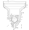
- FIG. 1 is a cross-sectional view showing a main portion of a solution container according to one embodiment of the present disclosure.
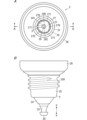
- FIG. 2 is a front view showing the liquid agent container according to the embodiment of the present invention.
- FIG. 3A is a plan view showing a nozzle provided in the liquid container of the same, in which a spherical valve provided in the same liquid container is omitted, and
- FIG. 3B is a front view showing the nozzle of the same.
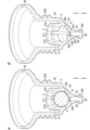
- FIG. 4A is a partially cutaway perspective view showing the nozzle and the spherical valve of the above embodiment
- FIG. 4B is a partially cutaway perspective view showing the nozzle of the above embodiment.
- a liquid agent container 1 of one embodiment includes a hollow cylindrical nozzle 2 having a discharge port 20 at its tip, a spherical valve 3 held in the nozzle 2, and a flexible container body 4 connected to the nozzle 2 and containing a liquid agent L1.
- the nozzle 2 has an abutment surface 21 that abuts against the spherical valve 3 in the circumferential direction, and a holding portion 22 that holds the spherical valve 3 in a state of abutting against the abutment surface 21.
- the abutment surface 21 is provided with a groove 5 that connects a space on the container body 4 side of the abutment surface 21 on the inside of the nozzle 2 with the discharge port 20.
- a groove 5 is provided on the contact surface 21 of the nozzle 2, which contacts the spherical valve 3 in the circumferential direction, connecting the space upstream of the contact surface 21 on the inside of the nozzle 2 with the discharge port 20. Therefore, in one embodiment of the liquid container 1, when the container body 4 is pressed, the liquid L1 in the container body 4 can be discharged from the discharge port 20 through the groove 5. In one embodiment of the liquid container 1, it is only necessary to appropriately set the cross-sectional area, etc. of the groove 5 formed in the nozzle 2 according to the viscosity of the liquid L1, so that it is easy to make a structure that corresponds to the viscosity of the liquid L1.
- liquid agent container 1 according to one embodiment shown in Fig. 1 to Fig. 4B will be described in more detail. Each component will be described below based on a usage state in which the discharge port 20 of the liquid agent container 1 faces vertically downward and the liquid agent L1 is dripped as shown in Fig. 2.
- the liquid container 1 comprises a hollow cylindrical nozzle 2 having an outlet 20 at its tip, a spherical valve 3 held within the nozzle 2, and a flexible container body 4 connected to the nozzle 2 and containing the liquid L1.
- the liquid container 1 of this embodiment further comprises a cap (not shown) that is removably attached to the nozzle 2. When attached to the nozzle 2, the cap closes the outlet 20 of the nozzle 2.
- the container body 4 shown in Fig. 2 is a container that contains the liquid agent L1.
- the container body 4 has flexibility.
- the container body 4 is a member with one end (specifically, the upper end) in the direction along the central axis of the cylinder closed.
- the container body 4 is formed of a sheet material such as aluminum, polyethylene, or polypropylene.
- the open lower end of the container body 4 is connected to the nozzle 2 and fixed by thermal welding or the like.
- the container body 4 is filled with, for example, 5 ml of liquid agent L1.
- the liquid L1 is a liquid having a viscosity of 50 to 3000 mPa ⁇ s.
- the liquid L1 is a cosmetic, a medicine, an adhesive, or the like.
- the liquid L1 is, for example, a liquid containing ascorbic acid. Ascorbic acid is a component that is prone to crystallization and discoloration.
- the spherical valve 3 is made of a synthetic resin such as polyethylene.
- the spherical valve 3 is attached inside the nozzle 2 and closes a part of the path connecting the space inside the container body 4 and the discharge port 20 of the nozzle 2.
- the nozzle 2 has a discharge port 20 for discharging the liquid agent L1, a contact surface 21 that contacts the spherical valve 3 in the circumferential direction, and a holding portion 22 that holds the spherical valve 3 in contact with the contact surface 21.
- the contact surface 21 is provided with a groove 5 that connects the discharge port 20 to a space on the container body 4 side (i.e., the upstream side in the discharge direction of the liquid agent L1) from the contact surface 21 on the inside of the nozzle 2.
- the nozzle 2 is a resin molded product made of synthetic resin such as polyethylene.
- the nozzle 2 is molded by an appropriate means such as injection molding.
- the nozzle 2 is hollow and cylindrical, and has a discharge outlet 20 at the tip (more specifically, the lower end).
- the nozzle 2 is connected to the container body 4 at its base end (more specifically, the upper end).
- the nozzle 2 has, from the tip to the base end, a tip tube section 23, an inclined tube section 24, an intermediate tube section 25, and a base end tube section 26.
- the tip tube section 23 is elongated and extends vertically, and has a nearly constant inner diameter.
- the tip (more specifically, the lower end) of the internal space 230 of the tip tube section 23 is the discharge port 20.
- the inclined tube portion 24 is continuous with the base end side (specifically, the upper side) of the tip tube portion 23, and the inner diameter and outer diameter become wider toward the base end side.
- the tip end (specifically, the lower end) of the inclined tube portion 24 is provided with a communication port 240 that communicates with the internal space 230 of the tip tube portion 23.
- the communication port 240 includes a large diameter portion 241 that is circular in plan view, a small diameter portion 242 that is circular in plan view and has a smaller diameter than the large diameter portion 241, and an enlarged diameter portion 243 that has a larger diameter toward the tip side.
- the enlarged diameter portion 243 communicates with the internal space 230 of the tip tube portion 23.
- the communication port 240 and the internal space 230 form the discharge flow path 28 that connects the groove 5 and the discharge port 20.
- the discharge flow path 28 has a larger flow path cross-sectional area than the groove 5.
- the portion of the inner circumferential surface 244 of the inclined cylindrical portion 24 surrounding the communication port 240 is the abutment surface 21 against which the spherical valve 3 abuts in the circumferential direction.
- the lower end of the inner circumferential surface 244 of the inclined cylindrical portion 24 constitutes the abutment surface 21.
- the intermediate tubular portion 25 is continuous with the base end side (specifically, the upper side) of the inclined tubular portion 24, and has a substantially constant inner diameter.
- the outer peripheral surface of the intermediate tubular portion 25 is provided with a helical thread 250 that is used for connecting to the cap.
- the base end tubular portion 26 is continuous with the base end side (specifically the upper side) of the intermediate tubular portion 25, and the inner and outer diameters increase toward the base end, while the inner and outer diameters are constant at the end portion toward the base end.
- the container body 4 is connected to the base end tubular portion 26.
- the open lower end of the container body 4 is fixed to the outer peripheral surface of the base end tubular portion 26 by an appropriate means such as heat welding.
- the nozzle 2 further has a cylindrical inner tube portion 27 that protrudes from the end portion (more specifically, the upper end portion) of the inner peripheral surface 244 of the inclined tube portion 24 toward the base end side (more specifically, the upper side).
- the inner tube portion 27 extends along the intermediate tube portion 25, and a gap S1 is formed between the inner tube portion 27 and the intermediate tube portion 25.
- the inner peripheral surface of the inner tube portion 27 is provided with a plurality of bulges 270 that protrude radially inward.
- the multiple bulges 270 are positioned at intervals in the circumferential direction of the inner tube portion 27.
- each of the three bulges 270 is a plate-like arc that protrudes radially outward.
- the three bulges 270 form the holding portion 22 that holds the spherical valve 3.
- a recess 271 that opens radially inward is formed between two circumferentially adjacent bulges 270.
- three recesses 271 are formed on the inner peripheral surface of the inner tube portion 27.
- a groove 5 is formed on the bottom surface of one of the three recesses 271 and on the inner peripheral surface 244 of the inclined tube portion 24.
- the groove 5 is formed from the upper end of the bottom surface of the recess 271 to the lower end of the inner peripheral surface 244.
- the groove 5 is formed on the abutment surface 21 that constitutes the lower end of the inner peripheral surface 244 of the inclined tube portion 24.
- One longitudinal end (specifically, the lower end) of the groove 5 is connected to a circumferential part of the large diameter portion 241 of the communication port 240 of the inclined tube portion 24.
- the other longitudinal end (specifically, the upper end) of the groove 5 is located closer to the container body 4 than the spherical valve 3 and opens toward the container body 4.
- only one groove 5 is provided on the inner peripheral surface of the inner tube portion 27 and the inner peripheral surface 244 of the inclined tube portion 24.
- only one groove 5 is provided on the abutment surface 21.
- the groove 5 is formed, for example, by performing a process to cut out a part of the inner peripheral surface of the inner tube portion 27 and a part of the inner peripheral surface 244 of the inclined tube portion 24.
- the groove 5 may be molded when the nozzle 2 is molded from resin.
- the groove 5 extends linearly when viewed from the center of the spherical valve 3.
- the groove 5 has a constant circumferential position from one end to the other end in the longitudinal direction (i.e., from the upper end to the lower end).
- the flow path cross-sectional area of the groove 5, i.e., the cross-sectional area of the groove 5 in an imaginary plane perpendicular to the longitudinal direction is, for example, 0.087 to 0.28 mm2 from one end to the other end in the longitudinal direction (i.e., from the upper end to the lower end).
- the liquid L1 has a viscosity of 50 to 3000 mPa ⁇ s and is a liquid containing ascorbic acid.
- the flow path cross-sectional area of the groove 5 is 0.087 to 0.28 mm2 .
- the user removes the cap from the liquid container 1 and holds the container body 4 with the fingers so that the discharge port 20 faces vertically downward as shown in FIG. 2.
- the viscosity of the liquid L1 and the flow path cross-sectional area of the groove 5 are within the above ranges, the liquid L1 does not drip from the discharge port 20 due to its own weight even if the discharge port 20 faces vertically downward.
- the force applied by the user is, for example, 2.6 to 15.0 N.
- the liquid L1 in the container body 4 drips from the discharge port 20 through the gaps between the four recesses 271 and the spherical valve 3, the gap between the inner circumferential surface 244 of the inclined tube portion 24 and the spherical valve 3, the gap between the abutment surface 21 and the spherical valve 3 (i.e., the groove 5), and the discharge flow path 28 (more specifically, the communication port 240 and the internal space 230).
- the amount of liquid L1 dripped is, for example, 0.03 to 0.30 ml.
- the user repeatedly presses the container body 4 according to the amount of liquid L1 required.
- the viscosity of the liquid L1 is less than 50 mPa ⁇ s, when the discharge port 20 is pointed downward, the liquid L1 passes through the groove 5 with a flow path cross-sectional area in the above range due to its own weight, and drips from the discharge port 20. Also, if the viscosity of the liquid L1 is higher than 3000 mPa ⁇ s, it is difficult to drip a predetermined amount of liquid L1 from the discharge port 20 even if the container body 4 is pressed with a force of 2.6 to 15.0 N.
- a groove 5 is provided in a portion of the inner circumferential surface of the nozzle 2 where the spherical valve 3 abuts and seals (i.e., the abutment surface 21).
- the spherical valve 3 abuts and seals (i.e., the abutment surface 21).
- the viscosity of the liquid L1 is 50 to 3000 mPa ⁇ s, and the flow path cross-sectional area of the groove 5 is 0.087 to 0.28 mm2. Therefore, in the liquid container 1 of this embodiment, if a user presses the container body 4 with a normal squeeze force (for example, 2.6 to 15.0 N), a predetermined amount of the liquid L1 can be dripped from the discharge port 20.
- a normal squeeze force is a force that a general user can apply without strain.
- the liquid L1 can be prevented from dripping from the discharge port 20 due to its own weight, so that a fixed amount of the liquid L1 can be easily dripped from the discharge port 20.
- the liquid agent L1 is a liquid containing ascorbic acid which is prone to crystallization
- the flow path cross-sectional area of the groove 5 is 0.087 to 0.28 mm2 , so that the groove 5 is not easily clogged and it is easy to drip a fixed amount of the liquid agent L1 from the discharge port 20.
- only one groove 5 is formed on the contact surface 21 of the inner circumferential surface of the nozzle 2, so the flow path cross-sectional area of the groove 5 can be made larger than when multiple grooves 5 are formed, and the groove 5 is less likely to become clogged.
- the groove 5 is provided linearly on the inner peripheral surface of the nozzle 2 when viewed from the center of the spherical valve 3, so the liquid L1 easily passes through the groove 5 and the groove 5 is less likely to become clogged.
- the spherical valve 3 can be held from three sides by the holding portion 22 consisting of three bulges 270, making it easier to maintain the state in which the spherical valve 3 abuts against the abutment surface 21, and the spherical valve 3 is less likely to come off.
- the groove 5 is formed not only on the contact surface 21, but also on the inner circumferential surface of the nozzle 2, in a portion upstream of the contact surface 21 and a portion downstream of the contact surface 21, and one end of the groove 5 is connected to the communication port 240. Therefore, in the liquid container 1 of this embodiment, the liquid L1 upstream of the spherical valve 3 can be easily sent along the groove 5 to the discharge port 20.
- the groove 5 is connected to the discharge flow path 28 (more specifically, the communication port 240 and the internal space 230) which has a larger flow path cross-sectional area than the groove 5, so that the liquid L1 that passes through the groove 5 flows smoothly through the discharge flow path 28 and is easily dripped from the discharge port 20.
- Tables 1 to 3 below show experimental results summarizing the viscosity of the liquid L1 filled in the liquid container 1, the flow path cross-sectional area of the groove 5 of the liquid container 1, the squeeze force required to drip one drop of the liquid L1 from the discharge port 20 of the liquid container 1, and the dripping from the downward discharge port 20 for a predetermined time (e.g., 5 seconds) when the liquid container 1 is held by hand without applying force.
- dripping is indicated as ⁇ when the liquid L1 falls from the discharge port 20 due to its own weight, and ⁇ when 50% or more of a drop of the liquid L1 comes out of the discharge port 20. ⁇ when less than 50% of a drop of the liquid L1 comes out of the discharge port 20, and ⁇ when no dripping at all.
- Table 1 below shows the experimental results of liquid containers 1 A1 to A7, which have a constant flow path cross-sectional area of 0.07 mm2 and different viscosities of the liquid L1.
- Table 2 shows the experimental results of liquid containers 1 B1 to B7, which have a constant flow path cross-sectional area of 0.087 mm2 and different viscosities of the liquid L1.
- Table 3 shows the experimental results of liquid containers 1 C1 to C4, which have a constant flow path cross-sectional area of 68 mPa s and different viscosities of the liquid L1.
- the liquid agent L1 is a liquid containing ascorbic acid and the flow path cross-sectional area of the groove 5 is as narrow as 0.07 mm2 as in the liquid agent containers 1 of A1 to A7, the groove 5 is likely to become clogged with crystals precipitated from the ascorbic acid over time, and the liquid agent L1 has difficulty in flushing away the crystals clogged in the groove 5. Therefore, in order to drip only one drop of the liquid agent L1 from the discharge port 20, a larger squeeze force is required, and therefore the flow path cross-sectional area of the groove 5 is preferably 0.087 to 0.28 mm2 .
- the nozzle 2 has a contact surface 21 that contacts the spherical valve 3 in the circumferential direction, and a holding portion 22 that holds the spherical valve 3 in contact with the contact surface 21.
- the contact surface 21 may have a groove 5 that connects the space on the inner side of the nozzle 2, which is closer to the container body 4 than the contact surface 21, to the discharge port 20.
- the structure of the nozzle 2 is not limited to the structure shown in FIG. 1, etc.
- Two or more grooves 5 may be provided on the contact surface 21. Furthermore, the grooves 5 do not have to extend in a straight line when viewed from the center of the spherical valve 3, and may extend, for example, in a curved or broken line.
- the flow path cross-sectional area of the groove 5 and the viscosity of the liquid L1 are not limited to the combinations in the ranges described above, and can be changed as appropriate.
- liquid L1 may be a liquid that does not contain ascorbic acid.
- the solution container (1) of the first aspect has the following configuration.
- the liquid container (1) of the first embodiment includes a hollow cylindrical nozzle (2) having an outlet (20) at its tip, a spherical valve (3) held within the nozzle (2), and a flexible container body (4) connected to the nozzle (2) and containing the liquid (L1).
- the nozzle (2) has an abutment surface (21) that abuts against the spherical valve (3) in the circumferential direction, and a holding portion (22) that holds the spherical valve (3) in abutment against the abutment surface (21).
- the abutment surface (21) has a groove (5) that connects the space on the container body (4) side of the abutment surface (21) on the inside of the nozzle (2) with the outlet (20).
- a groove (5) is provided on the contact surface (21) of the nozzle (2) that contacts the spherical valve (3) in the circumferential direction, connecting the space upstream of the contact surface (21) on the inside of the nozzle (2) with the discharge port (20). Therefore, in the liquid container (1) of the first embodiment, when the container body (4) is pressed, the liquid (L1) in the container body (4) can be discharged from the discharge port (20) through the groove (5). In the liquid container (1) of the first embodiment, it is only necessary to appropriately set the cross-sectional area, etc. of the groove (5) formed in the nozzle (2) according to the viscosity of the liquid (L1), so that it is easy to make a structure corresponding to the viscosity of the liquid (L1).
- the liquid container (1) of the second aspect additionally has the following configuration in addition to the configuration of the first aspect.
- the flow path cross-sectional area of the groove (5) required for dripping a predetermined amount of liquid (L1) from the discharge port (20) can be increased. Therefore, in the second embodiment of the liquid container (1), the liquid (L1) easily passes through the groove (5), the groove (5) is less likely to become clogged, and it is easy to keep the amount of liquid (L1) dripped from the discharge port (20) constant.
- the liquid container (1) of the third aspect additionally has the following configuration in addition to the configuration of the second aspect.
- the flow path cross-sectional area of the groove (5) is 0.087 to 0.28 mm2, and the viscosity of the liquid (L1) is 50 to 3000 mPa ⁇ s.
- liquid agent container (1) of the third aspect having the above configuration
- the liquid agent (L1) having a viscosity of 50 to 3000 mPa ⁇ s in the container body (4) can be discharged from the discharge port (20) through the groove (5) having a flow path cross-sectional area of 0.087 to 0.28 mm2 .
- liquid agent container (1) of the third aspect since the viscosity of the liquid agent (L1) and the flow path cross-sectional area of the groove (5) have the above-mentioned relationship, when the discharge port (20) is directed vertically downward, it is easy to prevent the liquid agent (L1) from passing through the groove (5) due to its own weight and being discharged from the discharge port (20). Therefore, in the liquid agent container (1) of the third aspect, when the container body (4) is pressed once, a fixed amount of the liquid agent (L1) can be easily dripped.
- the liquid container (1) of the fourth aspect additionally has the following configuration in addition to the configuration of the third aspect.
- the liquid (L1) contains ascorbic acid.
- liquid agent container (1) of the fourth embodiment having the above configuration, since the liquid agent (L1) contains ascorbic acid, crystals are likely to precipitate, but the groove (5) is not easily clogged and the liquid agent (L1) easily passes through the groove (5). Therefore, in the liquid agent container (1) of the fourth embodiment, even if crystals of the liquid agent (L1) precipitate, it is easy to drip a fixed amount of the liquid agent (L1) when the container body (4) is pressed once.
Landscapes
- Engineering & Computer Science (AREA)
- Mechanical Engineering (AREA)
- Closures For Containers (AREA)
- Containers And Packaging Bodies Having A Special Means To Remove Contents (AREA)
Abstract
Description
1.概要
図1に示すように、一実施形態の液剤容器1は、先端に吐出口20を有する中空筒状のノズル2と、ノズル2内に保持される球状弁3と、ノズル2に接続され、可撓性を有し、液剤L1が収容される容器本体4と、を備える。ノズル2は、球状弁3に周方向にわたって当接する当接面21と、当接面21に当接した状態の球状弁3を保持する保持部22とを有する。当接面21には、ノズル2の内側の当接面21よりも容器本体4側の空間と吐出口20とをつなぐ溝5が設けられている。
続いて、図1から図4Bに示す一実施形態の液剤容器1について更に詳しく説明する。以下では、図2に示すように、液剤容器1の吐出口20が鉛直方向の下方を向く状態であって、液剤L1を滴下させる使用状態を基準にして、各構成について説明する。
図2に示す容器本体4は、液剤L1を収容する容器である。容器本体4は、可撓性を有している。容器本体4は、筒の中心軸に沿った方向の一端(詳しくは上端)を閉じた部材である。容器本体4は、例えば、アルミニウム製、ポリエチレン製、又はポリプロピレン製などのシート材料で形成される。
液剤L1は、本実施形態では、粘度が50~3000mPa・sの液である。液剤L1は、化粧料、薬剤、又は接着剤等である。液剤L1は、例えば、アスコルビン酸を含有する液である。アスコルビン酸は、結晶が析出しやすく、変色しやすい成分である。
図1に示す球状弁3は、球状の弁体である。球状弁3は、例えば、ポリエチレン等の合成樹脂製である。球状弁3は、ノズル2内に取り付けられて、容器本体4内の空間とノズル2の吐出口20とをつなぐ経路の一部を塞ぐ。
図1、図3A、図3B、図4A及び図4Bに示すように、ノズル2は、液剤L1を吐出する吐出口20と、球状弁3に周方向にわたって当接する当接面21と、当接面21に当接した状態の球状弁3を保持する保持部22とを有する。当接面21には、ノズル2の内側の当接面21よりも容器本体4側(つまり液剤L1の吐出される方向における上流側)の空間と吐出口20とをつなぐ溝5が設けられている。
続いて、上述した液剤容器1の使用方法の一例について説明する。ここで、本実施形態の液剤容器1では、液剤L1は、粘度が50~3000mPa・sであり、アスコルビン酸を含有する液である。そして、溝5の流路断面積は、0.087~0.28mm2である。
以上説明した本実施形態の液剤容器1では、ノズル2の内周面のうち、球状弁3が当接してシールされる部分(つまり当接面21)の一部に、溝5が設けられている。本実施形態の液剤容器1では、この溝5の断面積等を、液剤L1の粘度に合わせて適宜設定するだけでよいため、従来例のように弾性膜体の厚みや材質を調整する場合に比べて、液剤L1の粘度に対応した構造としやすい。
続いて、液剤容器1の溝5の流路断面積と液剤L1の粘度についての比較を行った実験結果を説明する。液剤L1の粘度は、例えば、第十七改正日本薬局方に記載の方法で測定することができる。



続いて、上述した一実施形態の液剤容器1の変形例について説明する。以下に示す変形例は適宜組み合わせ可能である。
以上説明した一実施形態及びその変形例のように、第一態様の液剤容器(1)は、下記の構成を備える。
2 ノズル
20 吐出口
21 当接面
22 保持部
3 球状弁
4 容器本体
5 溝
L1 液剤
Claims (4)
- 先端に吐出口を有する中空筒状のノズルと、
前記ノズル内に保持される球状弁と、
前記ノズルと接続され、可撓性を有し、液剤が収容される容器本体と、を備え、
前記ノズルは、
前記球状弁に周方向にわたって当接する当接面と、
前記当接面に当接した状態の前記球状弁を保持する保持部と、を有し、
前記当接面には、前記ノズルの内側の前記当接面よりも前記容器本体側の空間と前記吐出口とをつなぐ溝が設けられている、
液剤容器。 - 前記当接面には、前記溝が一つのみ設けられ、
前記溝は、前記球状弁の中心から見て、直線状に延びている、
請求項1に記載の液剤容器。 - 前記溝の流路断面積は、0.087~0.28mm2であり、
前記液剤の粘度は、50~3000mPa・sである、
請求項2に記載の液剤容器。 - 前記液剤は、アスコルビン酸を含有している、
請求項3に記載の液剤容器。
Priority Applications (2)
| Application Number | Priority Date | Filing Date | Title |
|---|---|---|---|
| JP2025504002A JPWO2024181552A1 (ja) | 2023-03-01 | 2024-03-01 | |
| KR1020257032899A KR20250156786A (ko) | 2023-03-01 | 2024-03-01 | 액제 용기 |
Applications Claiming Priority (2)
| Application Number | Priority Date | Filing Date | Title |
|---|---|---|---|
| JP2023-031424 | 2023-03-01 | ||
| JP2023031424 | 2023-03-01 |
Publications (1)
| Publication Number | Publication Date |
|---|---|
| WO2024181552A1 true WO2024181552A1 (ja) | 2024-09-06 |
Family
ID=92589924
Family Applications (1)
| Application Number | Title | Priority Date | Filing Date |
|---|---|---|---|
| PCT/JP2024/007706 Ceased WO2024181552A1 (ja) | 2023-03-01 | 2024-03-01 | 液剤容器 |
Country Status (3)
| Country | Link |
|---|---|
| JP (1) | JPWO2024181552A1 (ja) |
| KR (1) | KR20250156786A (ja) |
| WO (1) | WO2024181552A1 (ja) |
Citations (2)
| Publication number | Priority date | Publication date | Assignee | Title |
|---|---|---|---|---|
| JP2004352252A (ja) * | 2003-04-04 | 2004-12-16 | Takeuchi Press Ind Co Ltd | 滴下機能付き容器 |
| JP2010089816A (ja) * | 2008-10-07 | 2010-04-22 | Takeuchi Press Ind Co Ltd | ヒンジキャップ付容器 |
Family Cites Families (1)
| Publication number | Priority date | Publication date | Assignee | Title |
|---|---|---|---|---|
| JP3961507B2 (ja) | 2004-04-16 | 2007-08-22 | 住友ゴム工業株式会社 | 逆流防止口栓および容器 |
-
2024
- 2024-03-01 KR KR1020257032899A patent/KR20250156786A/ko active Pending
- 2024-03-01 WO PCT/JP2024/007706 patent/WO2024181552A1/ja not_active Ceased
- 2024-03-01 JP JP2025504002A patent/JPWO2024181552A1/ja active Pending
Patent Citations (2)
| Publication number | Priority date | Publication date | Assignee | Title |
|---|---|---|---|---|
| JP2004352252A (ja) * | 2003-04-04 | 2004-12-16 | Takeuchi Press Ind Co Ltd | 滴下機能付き容器 |
| JP2010089816A (ja) * | 2008-10-07 | 2010-04-22 | Takeuchi Press Ind Co Ltd | ヒンジキャップ付容器 |
Also Published As
| Publication number | Publication date |
|---|---|
| KR20250156786A (ko) | 2025-11-03 |
| JPWO2024181552A1 (ja) | 2024-09-06 |
Similar Documents
| Publication | Publication Date | Title |
|---|---|---|
| US7874467B2 (en) | Metered drop push button dispenser system | |
| CN101553406B (zh) | 用于施加微升量的液滴形式的液体的可计量的滴瓶 | |
| US5582330A (en) | Specific volume dispenser | |
| CN101351387A (zh) | 持续密封单向阀装置和流体输送系统以及其中使用的配制物 | |
| US8851333B2 (en) | Dosing cap for container | |
| US6766816B2 (en) | Collapsible dispensing system | |
| CN104797219B (zh) | 液体分配器 | |
| US20090218373A1 (en) | Continuously sealing one way valve assembly and fluid delivery system and formulations for use therein | |
| EA022725B1 (ru) | Флакон для жидкости с раздаточной головкой для покапельной раздачи | |
| JP5318509B2 (ja) | 歯科用接着剤の保管容器 | |
| CA2736180A1 (en) | Metered drop push button dispenser system | |
| JP6653555B2 (ja) | 液体注出塗布容器とその使用方法 | |
| CN101495079B (zh) | 药物溶液滴管 | |
| WO2024181552A1 (ja) | 液剤容器 | |
| EP1779832A1 (en) | Squeeze bottle and eye drop container using the same | |
| JP7218125B2 (ja) | 滴下装置および滴下容器 | |
| CN103717499B (zh) | 具有用于可流动的产品的管嘴的包装 | |
| US11731810B2 (en) | Inverted dispensing container | |
| JP4263901B2 (ja) | 弁機構 | |
| JPS62120859A (ja) | 点滴薬分配器 | |
| JP2017532139A (ja) | 定量点眼器、および眼の表面への定量投与方法 | |
| KR20230154810A (ko) | 유리 주사기 점적기 | |
| HK1129218A (en) | Continuously sealing one way valve assembly and fluid delivery system formulations for use therein |
Legal Events
| Date | Code | Title | Description |
|---|---|---|---|
| 121 | Ep: the epo has been informed by wipo that ep was designated in this application |
Ref document number: 24764029 Country of ref document: EP Kind code of ref document: A1 |
|
| ENP | Entry into the national phase |
Ref document number: 2025504002 Country of ref document: JP Kind code of ref document: A |
|
| WWE | Wipo information: entry into national phase |
Ref document number: 2025504002 Country of ref document: JP |
|
| ENP | Entry into the national phase |
Ref document number: 1020257032899 Country of ref document: KR Free format text: ST27 STATUS EVENT CODE: A-0-1-A10-A15-NAP-PA0105 (AS PROVIDED BY THE NATIONAL OFFICE) |
|
| WWE | Wipo information: entry into national phase |
Ref document number: KR1020257032899 Country of ref document: KR |
|
| NENP | Non-entry into the national phase |
Ref country code: DE |
|
| 122 | Ep: pct application non-entry in european phase |
Ref document number: 24764029 Country of ref document: EP Kind code of ref document: A1 |