WO2024181534A1 - 制御対象に対するフィードフォワード制御に関する機械学習のための装置、教師データの生成プログラム、および教師データの生成方法 - Google Patents
制御対象に対するフィードフォワード制御に関する機械学習のための装置、教師データの生成プログラム、および教師データの生成方法 Download PDFInfo
- Publication number
- WO2024181534A1 WO2024181534A1 PCT/JP2024/007548 JP2024007548W WO2024181534A1 WO 2024181534 A1 WO2024181534 A1 WO 2024181534A1 JP 2024007548 W JP2024007548 W JP 2024007548W WO 2024181534 A1 WO2024181534 A1 WO 2024181534A1
- Authority
- WO
- WIPO (PCT)
- Prior art keywords
- value
- control
- combinations
- variable
- manipulated variable
- Prior art date
- Legal status (The legal status is an assumption and is not a legal conclusion. Google has not performed a legal analysis and makes no representation as to the accuracy of the status listed.)
- Ceased
Links
Images



Classifications
-
- G—PHYSICS
- G05—CONTROLLING; REGULATING
- G05B—CONTROL OR REGULATING SYSTEMS IN GENERAL; FUNCTIONAL ELEMENTS OF SUCH SYSTEMS; MONITORING OR TESTING ARRANGEMENTS FOR SUCH SYSTEMS OR ELEMENTS
- G05B11/00—Automatic controllers
- G05B11/01—Automatic controllers electric
- G05B11/32—Automatic controllers electric with inputs from more than one sensing element; with outputs to more than one correcting element
-
- G—PHYSICS
- G05—CONTROLLING; REGULATING
- G05B—CONTROL OR REGULATING SYSTEMS IN GENERAL; FUNCTIONAL ELEMENTS OF SUCH SYSTEMS; MONITORING OR TESTING ARRANGEMENTS FOR SUCH SYSTEMS OR ELEMENTS
- G05B13/00—Adaptive control systems, i.e. systems automatically adjusting themselves to have a performance which is optimum according to some preassigned criterion
- G05B13/02—Adaptive control systems, i.e. systems automatically adjusting themselves to have a performance which is optimum according to some preassigned criterion electric
-
- G—PHYSICS
- G05—CONTROLLING; REGULATING
- G05B—CONTROL OR REGULATING SYSTEMS IN GENERAL; FUNCTIONAL ELEMENTS OF SUCH SYSTEMS; MONITORING OR TESTING ARRANGEMENTS FOR SUCH SYSTEMS OR ELEMENTS
- G05B19/00—Program-control systems
- G05B19/02—Program-control systems electric
- G05B19/04—Program control other than numerical control, i.e. in sequence controllers or logic controllers
- G05B19/05—Programmable logic controllers, e.g. simulating logic interconnections of signals according to ladder diagrams or function charts
-
- G—PHYSICS
- G05—CONTROLLING; REGULATING
- G05B—CONTROL OR REGULATING SYSTEMS IN GENERAL; FUNCTIONAL ELEMENTS OF SUCH SYSTEMS; MONITORING OR TESTING ARRANGEMENTS FOR SUCH SYSTEMS OR ELEMENTS
- G05B23/00—Testing or monitoring of control systems or parts thereof
- G05B23/02—Electric testing or monitoring
Definitions
- the present disclosure relates to a machine learning device for feedforward control of a control target, a program for generating teacher data, and a method for generating teacher data.
- JP 4-326101 A discloses a neural network control device equipped with a disturbance occurrence detector that detects disturbances that affect a controlled system and controls the self-learning of a neural network feedforward compensator based on the disturbance detection value.
- the detection value of a disturbance affecting the controlled system is used for self-learning of a neural network type feedforward compensator.
- the disturbance affecting the controlled system may include multiple elements. If it is not possible to detect all of these, the self-learning using the detection value of the disturbance cannot extract an accurate relationship between the disturbance, including elements that have not been detected, and the feedforward compensation signal. As a result, the accuracy of prediction of the feedforward compensation signal by the neural network type feedforward compensator may decrease.
- This disclosure has been made to solve the problems described above, and its purpose is to improve the accuracy of feedforward control of the controlled object.
- An apparatus is an apparatus for machine learning for a predictive model that predicts a feedforward compensation value of a feedback manipulation variable to a controlled object subjected to a disturbance.
- the feedback manipulation variable is determined by feedback control of a control device of the controlled object based on an error between a target value and the control variable of the controlled object so that the control variable approaches a target value.
- the sum of the feedback manipulation variable and the feedforward compensation value is output from the control device to the controlled object as a manipulation variable.
- the disturbance includes a first element and a second element.
- the predictive model predicts the feedforward compensation value from a measured value of the first element.
- the apparatus is equipped with a learning data generation unit.
- the learning data generation unit identifies a plurality of second combinations including a measurement value and an operation amount based on a comparison between the error and a first reference value from among a plurality of first combinations including a target value, an operation amount corresponding to the target value, a measurement value, and a control amount corresponding to both the measurement value and the operation amount obtained at a plurality of timings, identifies a plurality of first components corresponding to a first element and a plurality of second components corresponding to a second element in the plurality of operation amounts included in each of the plurality of second combinations, and outputs teacher data in which the plurality of first components correspond as correct answers to the plurality of measurement values included in each of the second combinations at a plurality of timings.
- the correct answer that should correspond to the measured value is not the manipulated variable itself, but the first component of the manipulated variable that corresponds to the measured element that requires feedforward control, which is identified as the feedforward compensation value.
- an appropriate correct answer is associated with the measured value in the teacher data. Therefore, according to this disclosure, the accuracy of feedforward control for the controlled object can be improved by performing machine learning on the prediction model using the teacher data.
- the device further includes a learning unit that performs machine learning on the prediction model using teacher data.
- the learning unit approximates the relationship between the multiple measurement values and the multiple first components expressed by the prediction model as a function with the feedforward compensation value as the objective variable and the measurement value as the explanatory variable, and terminates the machine learning when the ratio of the number of fourth combinations, among the multiple second combinations, whose absolute values of the measurement values are greater than the second reference value to the number of third combinations, among the multiple first combinations, whose absolute values of the measurement values are greater than the second reference value, is greater than the third reference value.
- training data is selected from the results of feedforward control, so that the predictive model can be adapted in real time to the disturbances and characteristics of the controlled object in parallel with the feedforward control. Furthermore, according to this disclosure, machine learning continues until the accuracy of the predictive model is sufficiently high, so that the accuracy of the feedforward control for the controlled object can be sufficiently improved.
- the learning unit may resume machine learning when the machine learning is completed and the above ratio is smaller than a third reference value.
- the predictive model is re-adapted to the characteristics of the controlled object in response to changes in those characteristics, thereby preventing a decrease in the accuracy of feedforward control due to changes in the characteristics of the controlled object.
- the second element does not have to be measured. According to this disclosure, the cost of sensors and the like required to measure the second element can be reduced.
- a teacher data generation program is a program for machine learning for a predictive model that predicts a feedforward compensation value of a feedback manipulation amount for a control object that is subjected to a disturbance.
- the feedback manipulation amount is determined by feedback control of a control device for the control object based on an error between a target value and the control amount of the control object so that the control amount approaches a target value.
- the sum of the feedback manipulation amount and the feedforward compensation value is output from the control device to the control object as a manipulation amount.
- the disturbance includes a first element and a second element.
- the predictive model predicts the feedforward compensation value from the measured value of the first element.
- the program for generating teacher data is executed by a processor to identify, from among a plurality of first combinations including a target value, an operation amount corresponding to the target value, a measurement value, and a control amount corresponding to both the measurement value and the operation amount, a plurality of second combinations including a measurement value and an operation amount based on a comparison between the error and a first reference value, identify, for the plurality of operation amounts included in each of the plurality of second combinations, a plurality of first components corresponding to a first element and a plurality of second components corresponding to a second element, and output teacher data in which the plurality of first components correspond as correct answers to the plurality of measurement values included in each of the second combinations at the plurality of times.
- the correct answer to be associated with the measured value is not the manipulated variable itself, but a first component of the manipulated variable that corresponds to the measured element that requires feedforward control, which is identified as the feedforward compensation value.
- an appropriate correct answer is associated with the measured value in the teacher data. Therefore, according to this disclosure, the accuracy of feedforward control of the control target can be improved by performing machine learning on the prediction model using the teacher data.
- the invention according to this disclosure can also be realized as a non-transitory computer-readable medium that stores the above program.
- a method for generating teacher data is a method for machine learning for a predictive model that predicts a feedforward compensation value of a feedback manipulation variable for a control object that is subjected to a disturbance.
- the feedback manipulation variable is determined by feedback control of a control device for the control object based on an error between a target value and the control variable of the control object so that the control variable approaches a target value.
- the sum of the feedback manipulation variable and the feedforward compensation value is output from the control device to the control object as a manipulation variable.
- the disturbance includes a first element and a second element.
- the predictive model predicts the feedforward compensation value from the measured value of the first element.
- the method for generating teacher data includes: identifying, based on a comparison between an error and a first reference value, a plurality of second combinations including a measurement value and an operation amount from among a plurality of first combinations including a target value, an operation amount corresponding to the target value, a measurement value, and a control amount corresponding to both the measurement value and the operation amount, which are obtained at a plurality of timings; identifying, for the plurality of operation amounts included in each of the plurality of second combinations, a plurality of first components corresponding to a first element and a plurality of second components corresponding to a second element; and outputting teacher data in which the plurality of first components correspond as correct answers to the plurality of measurement values included in each of the second combinations at a plurality of timings.
- the correct answer that should correspond to the measured value is not the manipulated variable itself, but the first component of the manipulated variable that corresponds to the measured element that requires feedforward control, which is identified as the feedforward compensation value.
- an appropriate correct answer is associated with the measured value in the teacher data. Therefore, according to this disclosure, the accuracy of feedforward control for the controlled object can be improved by performing machine learning on the prediction model using the teacher data.
- the device, teacher data generation program, and teacher data generation method disclosed herein can improve the accuracy of feedforward control of a control target.
- FIG. 2 is a block diagram showing a functional configuration of a control device according to the first embodiment
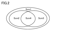
- FIG. FIG. 1 is a Venn diagram showing the inclusion relationships of four data sets each containing four combinations.
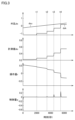
- 11A to 11C are diagrams showing time charts of disturbances, measured values, manipulated variables, and controlled variables during a trial period when a predictive model has not yet been learned.
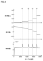
- 4 is a diagram showing measurement values, manipulated variables, and controlled variables obtained during the trial period shown in FIG. 3 when the absolute value of the error is smaller than a reference value.
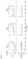
- FIG. 11 is a diagram for explaining a process of dividing an operation amount into a measured component and a non-measured component.
- FIG. 5(b) is a plot of points identified by the measurement values in FIG. 4 and the feedforward compensation values in FIG.
- FIG. 13 is a diagram for explaining a process of deriving a prediction function based on two data sets obtained in two trial periods.
- FIG. 13 is a diagram showing how the control amount is improved by increasing the number of trials for acquiring training data.
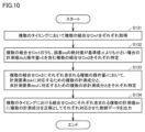
- FIG. 2 is a flowchart showing the flow of processing performed by each of a feedback control system, a feedforward control system, a learning data generating unit, and a learning unit in FIG. 1 .
- 10 is a flowchart showing a specific process flow of the learning data generation process of FIG. 9 .
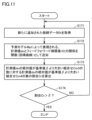
- 10 is a flowchart showing a specific process flow of the machine learning process in FIG. 9 .
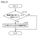
- FIG. 3 is a diagram showing a flow of additional learning processing performed by a learning unit in FIG. 2;
- FIG. 2 is a block diagram showing a functional configuration of a control device according to a first modified example of the first embodiment.
- FIG. 11 is a block diagram showing a functional configuration of a control system according to a second embodiment.
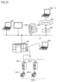
- FIG. 13 is a schematic diagram showing an example of a network configuration of a control system according to a third embodiment.
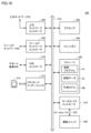
- 16 is a block diagram showing an example of a hardware configuration of the control device shown in FIG. 15 .
- Fig. 1 is a block diagram showing a functional configuration of a control device 100 according to embodiment 1.
- the control device 100 includes a feedback control unit 110, a feedforward compensation unit 120, a learning data generation unit 130, a storage unit 140, a subtractor 150, an adder 160, and a learning unit 170.
- the control device 100 outputs the sum of the feedback operation amount rb and the feedforward compensation value rf to the control object 200 as the operation amount r to the control object 200 so that the control amount q, which is the output value of the control object 200 subjected to the disturbance ds, approaches the target value qr.
- the memory unit 140 stores the prediction model Mp and the teacher data Dt.
- the control device 100 and the control object 200 are connected via a network (for example, the Internet or a cloud system) and may be located remotely from each other. Examples of machine learning algorithms for constructing the prediction model Mp include a deep binary tree or a support vector machine.
- the disturbance ds is a quantity that disturbs the state of a control system including the control device 100 and the controlled object 200.
- the disturbance ds includes multiple disturbance elements, including, for example, the amount of light, voltage, current, and temperature that are accidentally or suddenly input to the controlled object.
- the disturbance element that is measured by a measuring device such as a sensor is referred to as the measured element dsk (first element), and the disturbance element that is not measured is referred to as the non-measured element dsu (second element).
- the measured value of the measured element dsk is referred to as do.
- the multiple disturbance elements included in the disturbance ds can be determined as multiple factors that are expected to affect the quality characteristic value (control amount q) of the control object 200 based on previously obtained knowledge such as a characteristic factor diagram of the target device of the control object 200.
- a factor that causes a relatively large fluctuation in the control amount q in a reference time interval for feedback control is set as a measured element dsk
- a factor that causes a relatively small fluctuation in the control amount q or an unknown factor is set as a non-measured element dsu.
- the fluctuation of the control amount q based on the measured element in the reference time interval is larger than the fluctuation of the control amount q based on the non-measured element in the reference time interval.
- a factor that causes a steep or discontinuous fluctuation in the control amount q that is difficult to follow with feedback control is set as the measured element dsk.
- feedforward control for the measured element dsk which can prepare for steep fluctuations in advance.
- non-measured elements dsu factors that cause gradual or continuous fluctuations in the controlled variable q that can be tracked by feedback control (for example, the temperature around the controlled object, or the thermal expansion of the controlled object due to processing heat) are considered to be non-measured elements dsu. Since non-measured elements dsu can be tracked by feedback control, there is a relatively low need to perform feedforward control. Note that such factors may be considered to be non-measured elements in order to reduce the cost of sensors and the like required to measure them.
- the configuration including the feedback control unit 110 and the subtractor 150 will also be referred to as the feedback control system
- the configuration including the feedforward compensation unit 120 and the adder 160 will also be referred to as the feedforward control system.
- the feedback control unit 110 determines the feedback control variable rb based on the error eq and outputs it to the adder 160.
- the feedforward compensation unit 120 predicts the feedforward compensation value rf from the measured value do using the prediction model Mp and outputs it to the adder 160.
- the adder 160 outputs the sum of the feedback control variable rb and the feedforward compensation value rf as the controlled variable r to the control object 200 and the learning data generation unit 130.
- the learning data generating unit 130 generates teacher data Dt used in machine learning for the prediction model Mp.
- the learning data generating unit 130 obtains a plurality of combinations Cm1 (first combinations) including a target value qr, an operation amount r corresponding to the target value qr, a measurement value do, and a control amount q corresponding to both the measurement value do and the operation amount r at a plurality of timings.
- the learning data generating unit 130 identifies a plurality of combinations Cm2 (second combinations) including the measurement value do and the operation amount r when the absolute value of the error eq is smaller than a reference value ⁇ (first reference value) (when high-precision control is performed on the control object 200).
- the reference value ⁇ can be appropriately determined based on, for example, an actual machine experiment, a simulation, a product specification value, or a management value of a certain manufacturing process.
- the learning data generating unit 130 identifies a plurality of measurement components (first components) corresponding to the measurement element dsk and a plurality of non-measurement components (second components) corresponding to the non-measurement element dsu in the plurality of operation amounts r included in each of the plurality of combinations Cm2.
- the measurement components and the non-measurement components correspond to the feedforward compensation value rf and the feedback operation amount rb, respectively.
- the learning data generating unit 130 outputs the teacher data Dt in which the plurality of measurement components (correct answers) correspond to the plurality of measurement values do, respectively, to the storage unit 140.
- the teacher data Dt is stored in the storage unit 140, classified for each trial period for acquiring a set of learning data (data set).
- the learning data generating unit 130 may output the teacher data Dt directly to the learning unit 170.
- the learning unit 170 approximates the relationship between the measurement value do and the feedforward compensation value rf (measurement component) as a function (regression curve or regression surface) with the feedforward compensation value rf as the objective variable and the measurement value do as the explanatory variable.
- the prediction model Mp includes this function.
- the learning unit 170 determines that the number of timings at which high-precision control is performed on the control target 200 has increased to a desired level even if the measurement component of the disturbance ds is relatively large, and terminates machine learning for the prediction model Mp.
- the reference value ⁇ may be determined as the maximum absolute value of the measurement value do when the control system is in a steady state.
- the reference value ⁇ can be determined appropriately based on, for example, actual equipment experiments, simulations, product specifications, or manufacturing process control values.
- the learning unit 170 determines that the characteristics of the control object 200 have changed and resumes machine learning (additional learning) for the prediction model Mp.
- the reference value ⁇ can be determined appropriately based on, for example, actual machine experiments, simulations, product specifications, or management values for a certain manufacturing process.
- the characteristics of the control object 200 include, for example, the correspondence between the measured value d o and the manipulated variable r and the controlled variable q.
- FIG. 2 is a Venn diagram showing the inclusion relationship of four data sets Scm1, Scm2, Scm3, and Scm4, each of which includes four combinations Cm1 to Cm4.
- Data set Scm1 is a data set that includes all of the combinations Cm1 including the target value qr, the operation amount r, the measurement value do, and the control amount q.
- Data set Scm2 is a data set that includes all of the combinations Cm2 of data set Scm1 including the measurement value do and the operation amount r when the absolute value of the error eq is smaller than the reference value ⁇ .
- Data set Scm3 is a data set that includes all of the combinations Cm3 of data set Scm1 when the absolute value of the measurement value do is larger than the reference value ⁇ .
- Data set Scm4 is a data set that includes all of the combinations Cm4 of data set Scm2 where the absolute value of the measurement value do is larger than the reference value ⁇ . As shown in FIG. 5, data set Scm1 includes data sets Scm2 and Scm3. Dataset Scm4 is the intersection (intersection) of datasets Scm2 and Scm3.
- the correct answer to be made to correspond to the measurement value do among the operation amount r included in the feedforward control result is not the operation amount r itself, but the measurement component to correspond to the measurement element dsk that requires feedforward control, which is specified as the feedforward compensation value rf.
- the control device 100 since an appropriate correct answer is associated with the measurement value do in the teacher data Dt, the accuracy of the feedforward control for the control object 200 can be improved by performing machine learning on the prediction model Mp using the teacher data Dt.
- the prediction model Mp can be adapted in real time to the measurement value do and the characteristics of the control object 200 in parallel with the feedforward control.
- the accuracy of the feedforward control for the control object 200 can be sufficiently improved. Furthermore, since the prediction model Mp is re-adapted to the characteristics according to the change in the characteristics of the control object 200, the deterioration of the accuracy of the feedforward control due to the change in the characteristics of the control object 200 can be suppressed.
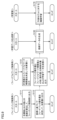
- FIG. 3 is a diagram showing time charts of disturbance ds, measurement value do, operation amount r, and control amount q during a trial period when the prediction model Mp has not yet been learned. 8,000 pieces of data acquired over 6,400 seconds are plotted in FIG. 3. As shown in FIG. 3, the measurement element dsk and the measurement value do change more abruptly at each of times t1, t2, t3, and t4 (t1 ⁇ t2 ⁇ t3 ⁇ t4) than in other time periods, and form a nearly flat step-like graph in other time periods. The non-measurement element dsu changes uniformly and continuously to form a linear graph.
- the operation amount r changes abruptly at each of times t1, t2, t3, and t4, similar to the measurement element dsk, and changes continuously at other time periods, similar to the non-measurement element dsu. Spike-like noise occurs in the control amount q at each of times t1, t2, t3, and t4.
- FIG. 4 shows the measurement value do, the operation amount r, and the control amount q obtained during the trial period shown in FIG. 3 when the absolute value of the error eq is smaller than the reference value ⁇ .
- FIG. 5 is a diagram for explaining the process of dividing the operation amount r into a measured component and a non-measured component.
- the operation amount r in FIG. 5(a) corresponds to the operation amount r in FIG. 4
- the operation amount r in FIG. 5(d) corresponds to the operation amount r in FIG. 3.
- the sample numbers on the horizontal axis in FIG. 4 and FIG. 5 are numbers assigned in the order in which the data was obtained. The same applies to FIG. 8, which will be explained later.
- the difference in (b) is the value (r n+1 -r n ) obtained by subtracting the nth operation amount r n from the n+1th operation amount r n+1 in (a).
- outliers ot1, ot2, ot3, and ot4 are detected at times t1 to t4, respectively.
- Each of the outliers ot1 to ot4 is a difference having an absolute value (
- (c) plots the non-measured components extracted by performing offset processing on each of the multiple data shown in (a).
- the offset processing the sum of outliers corresponding to the time of measurement is subtracted from each of the multiple data.
- the outlier subtracted from the operation amount r from time 0 (start of measurement) to time t1 is ot0.
- the outlier subtracted from the operation amount r from time t1 to t2 is the sum of ot0 and ot1.
- the outlier subtracted from the operation amount r from time t2 to t3 is the sum of ot0 to ot2.
- the outlier subtracted from the operation amount r from time t3 to t4 is the sum of ot0 to ot3.
- the outlier subtracted from the operation amount r after time t4 is the sum of ot0 to ot4.
- the non-measured components of the operation amount r are operation amounts determined by feedback control to correspond to the non-measured element dsu. Therefore, the unmeasured component of the manipulated variable r that is approximated as a function in this way is shown as the feedback manipulated variable rb in (d).
- the manipulated variable r is the sum of the feedback manipulated variable rb and the feedforward compensation value rf. Therefore, in (d), the feedforward compensation value rf is derived by subtracting the feedback manipulated variable rb from the manipulated variable r.
- FIG. 6 is a diagram in which points identified by the measurement value do in FIG. 4 and the feedforward compensation value rf in FIG. 5(d), which have the same sample number (measurement time), are plotted.
- FIG. 6 by regression analysis based on the plotted multiple points (teacher data), the correspondence between the measurement value do and the feedforward compensation value rf is approximated as a prediction function Fn1 having the measurement value do and the feedforward compensation value rf as explanatory variables and objective variables, respectively.
- a machine learning algorithm such as Gaussian process regression can be used to approximate the correspondence between the measurement value do and the feedforward compensation value rf as a function.
- FIG. 7 is a diagram for explaining the process of deriving the prediction function Fn12 based on two data sets acquired in two trial periods Tp1 and Tp2.
- the feedforward compensation value rf of the point (teacher data) derived in each of the trial periods Tp1 and Tp2 is subtracted by an offset value to be used as new teacher data, and the prediction function Fn12 is derived.
- the offset value may also be determined using the measurement value do12 included in the overlapping range Rg of the prediction functions Fn1 and Fn2 corresponding to the trial periods Tp1 and Tp2, respectively.
- the absolute value of the difference between the average value rfa of the feedforward compensation values rf1 and rf2 corresponding to the measurement value do12 in the prediction functions Fn1 and Fn2 and the feedforward compensation value rf1 or rf2 (half the difference between the feedforward compensation values rf1 and rf2) can be used as the offset value.
- the offset value may also be determined so that the sum of the offset values for all points included in the two trial periods Tp1 and Tp2 is minimized.
- FIG. 8 is a diagram showing how the control quantity q improves by increasing the number of trials for acquiring teacher data.
- spike-like noise occurs at times t11, t12, t13, and t14 in the first trial period.
- the magnitude of the spike-like noise occurring at times t21, t22, t23, and t24 in the second trial period and the magnitude of the spike-like noise occurring at times t31, t32, t33, and t34 in the third trial period are smaller than the magnitude of the spike-like noise occurring at times t11, t12, t13, and t14 in the first trial period.
- FIG. 9 is a diagram showing a flowchart illustrating the flow of processing performed by each of the feedback control system, the feedforward control system, the learning data generation unit 130, and the learning unit 170 in FIG. 1.
- the routines corresponding to the flowcharts of the feedback control system and the feedforward control system are executed, for example, at each sampling time.
- the routines corresponding to the flowcharts of the learning data generation unit 130 and the learning unit 170 are executed, for example, in response to the first execution of the routines corresponding to the flowcharts of the feedforward control system. Below, steps are simply abbreviated as S.
- the subtractor 150 calculates the error eq between the target value qr and the controlled variable q, and outputs it to the feedback control unit 110.
- the feedback control unit 110 determines the feedback control variable rb based on the error eq, outputs it to the adder 160, and ends the process.
- the feedforward compensation unit 120 determines a feedforward compensation value rf from the measurement value do and outputs it to the adder 160.
- the adder 160 outputs the sum of the feedback control amount rb and the feedforward compensation value rf as the control amount r to the control object 200 and the learning data generation unit 130, and ends the process.
- the training data generation unit 130 generates training data Dt in S130 and ends the process.
- the learning unit 170 performs machine learning on the prediction model Mp using the training data Dt in S170 and ends the process.
- the learning data generation unit 130 acquires a plurality of combinations Cm1 at a plurality of timings, and proceeds to S132.
- the learning data generation unit 130 identifies a plurality of combinations Cm2 including the measurement value do and the operation amount r when the absolute value of the error eq is smaller than the reference value ⁇ , from among the plurality of combinations Cm1, and proceeds to S133.
- the learning data generation unit 130 identifies a plurality of measurement components corresponding to the measurement element dsk and a plurality of non-measurement components corresponding to the non-measurement element dsu in the plurality of operation amounts r included in each of the plurality of combinations Cm2, and proceeds to S134.
- the learning data generation unit 130 outputs teacher data Dt in which multiple measurement components (feedforward compensation values rf) correspond to multiple measurement values do included in the combinations Cm2 at multiple timings as correct answers, and ends the process.
- FIG. 11 is a flowchart showing a specific process flow of the machine learning process S170 of FIG. 9.
- the learning unit 170 acquires newly added teacher data Dt and proceeds to S172.
- the learning unit 170 approximates the relationship between the measurement value do expressed by the prediction model Mp and the feedforward compensation value rf as a measurement component of the operation amount r as a function (regression curve) with the feedforward compensation value rf as the objective variable and the measurement value do as the explanatory variable, and proceeds to S173.
- the learning unit 170 determines whether the ratio Cr is greater than the reference value ⁇ . If the ratio Cr is equal to or less than the reference value ⁇ (NO in S174), the learning unit 170 determines that the accuracy of the feedforward control of the control object 200 is insufficient, and returns the process to S171. If the ratio Cr is greater than the reference value ⁇ (YES in S174), the learning unit 170 determines that the accuracy of the feedforward control of the control object 200 has increased sufficiently, and ends the machine learning.
- FIG. 12 is a diagram showing the flow of additional learning processing performed by the learning unit 170 of FIG. 2.
- the processing shown in FIG. 12 is executed at each sampling time, for example, after the initial machine learning is started.
- the learning unit 170 determines whether the machine learning is finished and the ratio Cr is equal to or less than the reference value ⁇ . If the machine learning is not finished or the ratio Cr is greater than the reference value ⁇ (NO in S171A), the learning unit 170 determines that the characteristics of the control object 200 have not changed and the existing learned prediction model Mp is adapted to the control object 200, and ends the processing.
- the learning unit 170 determines that the characteristics of the control object 200 have changed after the previous machine learning is finished, and resumes machine learning on the prediction model Mp in S170 similar to FIG. 9 in order to re-adapt the prediction model Mp to the characteristics of the control object 200. According to the control device 100, additional learning is performed on the prediction model Mp in response to changes in the characteristics of the control object 200, so that a decrease in the accuracy of feedforward control due to changes in the characteristics of the control object 200 can be suppressed.
- FIG. 13 is a block diagram showing the functional configuration of control device 100A according to variation 1 of embodiment 1.
- Control device 100A has a configuration in which subtractor 150 and feedback control unit 110 are removed from control device 100 in FIG. 1. Since the rest of the configuration is similar, the description of the similar configuration will not be repeated. Note that adder 160 does not have to be included in control device 100A.
- the control device 100A determines a feedforward compensation value rf of the feedback operation amount rb to the control object 200 such that the control amount q of the control object 200 receiving the measurement value do approaches a target value qr.
- the existing feedback control system can be easily expanded into a feedforward control system and a control system including a learning function.
- the device and the method for generating teacher data according to the first embodiment and the first modification can improve the accuracy of feedforward control of the control object.
- FIG. 14 is a block diagram showing the functional configuration of a control system 2 according to embodiment 2.
- components with the same reference symbols as those in FIG. 1 have the same functions as the components identified by the reference symbols described in embodiment 1, and therefore the description of the similar components will not be repeated.
- the control system 2 includes a feedback control device 11, a feedforward compensation device 12, a learning data generation device 13, a storage device 14, and a learning device 17.
- the learning data generation device 13, the storage device 14, and the learning device 17 correspond to the learning data generation unit 130, the storage unit 140, and the learning unit 170 in FIG. 1, respectively.
- the feedback control device 11 includes a feedback control unit 110 and a subtractor 150.
- the feedforward compensation device 12 includes a feedforward compensation unit 120 and an adder 160.
- the feedback control device 11, the feedforward compensation device 12, the learning data generation device 13, the storage device 14, the learning device 17, and the control target 200 may be connected to each other via a network and may be located remotely from each other.
- the adder 160 may be included in the feedback control device 11, not in the feedforward compensation device 12.
- an existing control system can be easily expanded by adding a feedforward compensation device, a learning data generation device, and a learning device to the existing feedback control device while leaving the existing feedback control device in place.
- the device and method for generating teacher data according to the second embodiment can improve the accuracy of feedforward control of the control object.
- Fig. 15 is a schematic diagram showing an example of a network configuration of a control system 3 according to embodiment 3.
- the control system 3 includes a device group in which a plurality of devices are configured to be able to communicate with each other.
- the devices may include a control device 300 that is a processing entity that executes a control program, and peripheral devices connected to the control device 300.
- the control device 300 has a functional configuration similar to that of the control device 100 shown in Fig. 1.
- the control device 300 corresponds to an industrial controller that controls control targets such as various facilities or devices.
- the control device 300 is a type of computer that executes control calculations, and typically includes a PLC (Programmable Logic Controller).
- the control device 300 is connected to a field device 200C via a field network 20.
- the control device 300 exchanges data with at least one field device 200C via the field network 20.
- the control calculations executed in the control device 300 include a process of collecting data collected or generated in the field device 200C, a process of generating data such as a command value (operation amount) for the field device 200C, and a process of transmitting the generated output data to the target field device 200C.
- the data collected or generated in the field device 200C includes data on disturbances input to the field device 200C, and a control amount resulting from the actual operation of the field device 200C in accordance with the command value.
- the command value for the field device 200C is determined by adding a feedforward compensation value predicted from the disturbance by a prediction model to a manipulation amount provisionally calculated based on the error between a control target value (target value) calculated based on the control program executed by the control device 300 and the actual control amount.
- the field network 20 preferably employs a bus or network that performs periodic communication.
- Known examples of such buses or networks that perform periodic communication include EtherCAT (registered trademark), EtherNet/IP (registered trademark), DeviceNet (registered trademark), and CompoNet (registered trademark).
- EtherCAT registered trademark
- EtherNet/IP registered trademark
- DeviceNet registered trademark
- CompoNet registered trademark
- the field device 200C includes an actuator that exerts some kind of physical action on a robot or conveyor in the field, and an input/output device that exchanges information with the field.
- the field device 200C includes a plurality of servo drivers 220_1 and 220_2, and a plurality of servo motors 222_1 and 222_2 connected to the plurality of servo drivers 220_1 and 220_2, respectively.
- the field device 200C is an example of a "control target.”
- Servo drivers 220_1 and 220_2 drive corresponding servo motors of servo motors 222_1 and 222_2 according to command values (such as position command values or speed command values) from control device 300. In this way, control device 300 can control field device 200C.
- command values such as position command values or speed command values
- the control device 300 is also connected to other devices via a higher-level network 32.
- the higher-level network 32 is connected to the Internet 900, which is an external network, via a gateway 700.
- the higher-level network 32 may use Ethernet (registered trademark) or EtherNet/IP (registered trademark), which are common network protocols. More specifically, at least one server device 600 and at least one display device 500 may be connected to the higher-level network 32.
- the server device 600 may be a database system or a manufacturing execution system (MES).
- the manufacturing execution system acquires information from the controlled manufacturing device or facility to monitor and manage the entire production, and may also handle order information, quality information, shipping information, and the like.
- a device that provides an information system service may be connected to the upper network 32.
- An example of an information system service is processing that acquires information from the controlled manufacturing device or facility and performs macro or micro analysis.
- an example of an information system service is data mining that extracts some characteristic tendency contained in information from the controlled manufacturing device or facility, or a machine learning tool that performs machine learning based on information from the controlled facility or machine.
- the display device 500 receives operations from the user and outputs commands to the control device 300 in response to the user operations, and also graphically displays the results of calculations performed by the control device 300.
- the support device 400 can be connected to the control device 300.
- the support device 400 may be connected to the control device 300 via the higher-level network 32 or the Internet 900.
- the support device 400 is a device that assists the control device 300 in making the necessary preparations to control the control target.
- the support device 400 provides a development environment (program creation and editing tools, parsers, compilers, etc.) for programs executed by the control device 300, a setting environment for setting configuration information (configuration) for the control device 300 and various devices connected to the control device 300, a function for outputting the generated program to the control device 300, and a function for modifying and changing the program executed on the control device 300 online.
- control device 300 the control device 300, the support device 400, and the display device 500 are each configured as separate entities, but a configuration may be adopted in which all or part of these functions are integrated into a single device.
- the control device 300 is not limited to being used at one production site, but may also be used at other production sites. It may also be used at multiple different lines at one production site.
- Fig. 16 is a block diagram showing an example of a hardware configuration of the control device 300 in Fig. 15.
- the control device 300 includes a processor 302, a main memory 304, a storage 360, a memory card interface 312, a host network controller 306, a field network controller 308, a local bus controller 316, and a Universal Serial Bus (USB) controller 370 that provides a USB interface.
- a processor bus 318 the control device 300 includes a main memory 304, a storage 360, a memory card interface 312, a host network controller 306, a field network controller 308, a local bus controller 316, and a Universal Serial Bus (USB) controller 370 that provides a USB interface.
- USB Universal Serial Bus
- the processor 302 corresponds to a calculation processing unit that executes control calculations, and is composed of a CPU (Central Processing Unit) and/or a GPU (Graphics Processing Unit), etc. Specifically, the processor 302 reads out a program stored in the storage 360, expands it in the main memory 304, and executes it to realize control calculations for a control target.
- a CPU Central Processing Unit
- GPU Graphics Processing Unit
- the main memory 304 is composed of a volatile storage device such as a dynamic random access memory (DRAM) and/or a static random access memory (SRAM).
- the storage 360 is composed of a non-volatile storage device such as a solid state drive (SSD) and/or a hard disk drive (HDD).
- Storage 360 stores control program Pc, teacher data Dt, and prediction model Mp. Storage 360 corresponds to memory unit 140 in FIG. 1.
- Control program Pc includes a program for comprehensively controlling control device 300 and realizing each function of control device 300.
- processor 302 that executes control program Pc corresponds to the feedback control system (feedback control unit 110 and subtractor 150), feedforward control system (feedforward compensation unit 120 and adder 160), learning data generation unit 130, and learning unit 170 in FIG. 1.
- the memory card interface 312 accepts a memory card 314, which is an example of a removable storage medium.
- the memory card interface 312 is capable of reading and writing any data to the memory card 314.
- the upper network controller 306 exchanges data with any information processing device connected to the upper network 32 (e.g., a local area network) via the upper network 32.
- the upper network 32 e.g., a local area network
- the field network controller 308 exchanges data with any device, such as servo motors 222_1 and 222_2, via the field network 20.
- the local bus controller 316 exchanges data with any of the functional units 380 constituting the control device 300 via the local bus 122.
- the functional units 380 include, for example, an analog I/O unit responsible for input and/or output of analog signals, a digital I/O unit responsible for input and/or output of digital signals, and a counter unit that receives pulses from an encoder or the like.
- the USB controller 370 exchanges data with any information processing device via a USB connection.
- the support device 400 is connected to the USB controller 370.
- the device, teacher data generation program, and teacher data generation method according to the third embodiment can improve the accuracy of feedforward control of a control target.
- the feedback manipulated variable (rb) is determined by feedback control of a control device of the controlled object based on an error (eq) between a target value (qr) and a controlled variable (q) of the controlled object (200) so that the controlled variable (q) approaches the target value (qr);
- the sum of the feedback operation amount (rb) and the feedforward compensation value (rf) is output from the control device to the control target (200) as an operation amount (r);
- the disturbance (ds) includes a first element (dsk) and a second element (dsu),
- the prediction model (Mp) predicts the feedforward compensation value (rf) from the measurement value (do) of the first element (dsk),
- the device (100) includes a learning
- [Configuration 2] A learning unit that performs the machine learning on the prediction model (Mp) using the teacher data (Dt),
- the learning unit (170) The relationship between the plurality of measurement values (do) and the plurality of first components (rf), which is expressed by the prediction model (Mp), is approximated as a function having the feedforward compensation value (rf) as a response variable and the measurement values (do) as explanatory variables;
- the device (100) described in configuration 1 terminates the machine learning when a ratio of a number of fourth combinations (Cm2) in which the absolute value of the measurement value (do) is greater than the second reference value to a number of third combinations (Cm1) in which the absolute value of the measurement value (do) is greater than the second reference value is greater than a third reference value.
- the feedback manipulated variable (rb) is determined by feedback control of a control device of the controlled object based on an error (eq) between a target value (qr) and a controlled variable (q) of the controlled object (200) so that the controlled variable (q) approaches the target value (qr);
- the sum of the feedback operation amount (rb) and the feedforward compensation value (rf) is output from the control device to the control target (200) as an operation amount (r);
- the disturbance (ds) includes a first element (dsk) and a second element (dsu),
- the prediction model (Mp) predicts the feedforward compensation value (rf) from the measurement value (do) of the first element (dsk),
- the program for generating teacher data is executed
- the feedback manipulated variable (rb) is determined by feedback control of a control device of the controlled object based on an error (eq) between a target value (qr) and a controlled variable (q) of the controlled object (200) so that the controlled variable (q) approaches the target value (qr);
- the sum of the feedback operation amount (rb) and the feedforward compensation value (rf) is output from the control device to the control target (200) as an operation amount (r);
- the disturbance (ds) includes a first element (dsk) and a second element (dsu),
- the prediction model (Mp) predicts the feedforward compensation value (rf) from the measurement value (do) of the first element (dsk),
- the method further includes a method of performing the machine learning on the prediction model (Mp) using the teacher data (Dt) to generate a trained model
- the method for generating the trained model includes: A step of approximating a relationship between the plurality of measurement values (do) and the plurality of first components (rf), which is expressed by the prediction model (Mp), as a function having the feedforward compensation value (rf) as a response variable and the measurement values (do) as explanatory variables; and terminating the machine learning when a ratio of a number of fourth combinations (Cm2) in which the absolute value of the measurement value (do) is greater than the second reference value to a number of third combinations (Cm1) in which the absolute value of the measurement value (do) is greater than the second reference value is greater than a third reference value.
- Cm2 a number of fourth combinations
- Cm1 third combinations
Landscapes
- Engineering & Computer Science (AREA)
- Physics & Mathematics (AREA)
- General Physics & Mathematics (AREA)
- Automation & Control Theory (AREA)
- Computer Vision & Pattern Recognition (AREA)
- Artificial Intelligence (AREA)
- Health & Medical Sciences (AREA)
- Evolutionary Computation (AREA)
- Medical Informatics (AREA)
- Software Systems (AREA)
- Feedback Control In General (AREA)
- Testing And Monitoring For Control Systems (AREA)
- Programmable Controllers (AREA)
Abstract
制御対象に対するフィードフォワード制御の精度を向上させる。装置(100)は、複数の第1組合せのうち、誤差(eq)と第1基準値との比較に基づいて、計測値(do)と操作量(r)とを含む複数の第2組合せをそれぞれ特定し、複数の第2組合せにそれぞれ含まれる複数の操作量(r)において、第1要素(dsk)に対応するための複数の第1成分(rf)と、第2要素(dsu)に対応するための複数の第2成分(rb)とをそれぞれ特定し、複数のタイミングにおける第2組合せにそれぞれ含まれる複数の計測値(do)に複数の第1成分(rf)を正解としてそれぞれ対応させた教師データ(Dt)を出力する。
Description
本開示は、制御対象に対するフィードフォワード制御に関する機械学習のための装置、教師データの生成プログラム、および教師データの生成方法に関する。
従来、制御対象に対してフィードフォワード制御を行なう構成が知られている。たとえば、特開平4-326101号公報(特許文献1)には、被制御系に影響を及ぼす外乱を検出しその外乱検出値によってニューラルネットワーク型フィードフォワード補償器の自己学習を制御する外乱発生検知器を備えるニューラルネットワーク制御装置が開示されている。
特許文献1に開示されている構成においては、被制御系に影響を及ぼす外乱の検出値がニューラルネットワーク型フィードフォワード補償器の自己学習に使用される。この点、被制御系に影響を及ぼす外乱には、複数の要素が含まれる場合がある。これらをすべて検出することができない場合、外乱の検出値が用いられる自己学習によっては、検出されていない要素を含む外乱とフィードフォワード補償信号との正確な関係性を抽出することができない。その結果、ニューラルネットワーク型フィードフォワード補償器によるフィードフォワード補償信号の予測の精度が低下し得る。
本開示は上記のような課題を解決するためになされたものであり、その目的は、制御対象に対するフィードフォワード制御の精度を向上させることである。
本開示の一局面に係る装置は、外乱を受ける制御対象へのフィードバック操作量のフィードフォワード補償値を予測する予測モデルに対する機械学習のための装置である。フィードバック操作量は、目標値と制御対象の制御量との誤差に基づいて、制御量が目標値に近づくように制御対象の制御装置のフィードバック制御によって決定される。フィードバック操作量およびフィードフォワード補償値の和が、操作量として制御対象に制御装置から出力される。外乱は、第1要素と、第2要素とを含む。予測モデルは、第1要素の計測値からフィードフォワード補償値を予測する。装置は、学習データ生成部を備える。学習データ生成部は、複数のタイミングにおいて取得された、目標値と、目標値に対応する操作量と、計測値と、計測値および操作量の両方に対応する制御量とを含む複数の第1組合せのうち、誤差と第1基準値との比較に基づいて、計測値と操作量とを含む複数の第2組合せをそれぞれ特定し、複数の第2組合せにそれぞれ含まれる複数の操作量において、第1要素に対応するための複数の第1成分と、第2要素に対応するための複数の第2成分とをそれぞれ特定し、複数のタイミングにおける第2組合せにそれぞれ含まれる複数の計測値に複数の第1成分を正解としてそれぞれ対応させた教師データを出力する。
この開示によれば、フィードフォワード制御の結果に含まれる操作量のうち、計測値に対応させるべき正解として、操作量そのものではなく、操作量のうちフィードフォワード制御が必要な計測要素に対応するための第1成分がフィードフォワード補償値として特定される。その結果、教師データにおいて計測値に対して適切な正解が関連付けられる。そのため、この開示によれば、教師データを用いて予測モデルに対して機械学習を行うことにより、制御対象に対するフィードフォワード制御の精度を向上させることができる。
上記の開示において、装置は、教師データを用いて予測モデルに対して機械学習を行う学習部をさらに備える。学習部は、予測モデルによって表現される、複数の計測値と複数の第1成分との関係を、フィードフォワード補償値を目的変数とするとともに、計測値を説明変数とする関数として近似し、複数の第1組合せのうち計測値の絶対値が第2基準値より大きい第3組合せの数に対する、複数の第2組合せのうち計測値の絶対値が第2基準値より大きい第4組合せの数の割合が第3基準値より大きい場合、機械学習を終了する。
この開示によれば、フィードフォワード制御の結果から教師データが選択されるため、フィードフォワード制御と並行して外乱および制御対象の特性に予測モデルをリアルタイムに適合させることができる。また、この開示によれば、予測モデルの精度が十分に高くなるまで機械学習が継続されるため、制御対象に対するフィードフォワード制御の精度を十分に向上させることができる。
上記の開示において、学習部は、機械学習が終了し、かつ、上記割合が第3基準値より小さい場合、機械学習を再開してもよい。
この開示によれば、制御対象の特性の変化に応じて予測モデルが当該特性に再適合されるため、制御対象の特性の変化によるフィードフォワード制御の精度の低下を抑制することができる。
上記の開示において、第2要素は、計測されなくてもよい。
この開示によれば、第2要素の計測に必要なセンサ等のコストを削減することができる。
この開示によれば、第2要素の計測に必要なセンサ等のコストを削減することができる。
本開示の他の局面に係る教師データの生成プログラムは、外乱を受ける制御対象へのフィードバック操作量のフィードフォワード補償値を予測する予測モデルに対する機械学習のためのプログラムである。フィードバック操作量は、目標値と制御対象の制御量との誤差に基づいて、制御量が目標値に近づくように制御対象の制御装置のフィードバック制御によって決定される。フィードバック操作量およびフィードフォワード補償値の和が、操作量として制御対象に制御装置から出力される。外乱は、第1要素と、第2要素とを含む。予測モデルは、第1要素の計測値からフィードフォワード補償値を予測する。教師データの生成プログラムは、プロセッサに実行されることによって、複数のタイミングにおいて取得された、目標値と、目標値に対応する操作量と、計測値と、計測値および操作量の両方に対応する制御量とを含む複数の第1組合せのうち、誤差と第1基準値との比較に基づいて、計測値と操作量とを含む複数の第2組合せをそれぞれ特定し、複数の第2組合せにそれぞれ含まれる複数の操作量において、第1要素に対応するための複数の第1成分と、第2要素に対応するための複数の第2成分とをそれぞれ特定し、複数のタイミングにおける第2組合せにそれぞれ含まれる複数の計測値に複数の第1成分を正解としてそれぞれ対応させた教師データを出力する。
この開示によれば、フィードフォワード制御の結果に含まれる操作量のうち、計測値に対応させるべき正解として、操作量そのものではなく、操作量のうちフィードフォワード制御が必要な計測要素に対応するための第1成分がフィードフォワード補償値として特定される。その結果、教師データにおいて計測値に対して適切な正解が関連付けられる。そのため、この開示によれば、教師データを用いて予測モデルに対して機械学習を行うことにより、制御対象に対するフィードフォワード制御の精度を向上させることができる。なお、本開示に係る発明は、上記プログラムを記憶する非一時的なコンピュータ可読媒体としても実現可能である。
本開示の他の局面に係る教師データの生成方法は、外乱を受ける制御対象へのフィードバック操作量のフィードフォワード補償値を予測する予測モデルに対する機械学習のための方法である。フィードバック操作量は、目標値と制御対象の制御量との誤差に基づいて、制御量が目標値に近づくように制御対象の制御装置のフィードバック制御によって決定される。フィードバック操作量およびフィードフォワード補償値の和が、操作量として制御対象に制御装置から出力される。外乱は、第1要素と、第2要素とを含む。予測モデルは、第1要素の計測値からフィードフォワード補償値を予測する。教師データの生成方法は、複数のタイミングにおいて取得された、目標値と、目標値に対応する操作量と、計測値と、計測値および操作量の両方に対応する制御量とを含む複数の第1組合せのうち、誤差と第1基準値との比較に基づいて、計測値と操作量とを含む複数の第2組合せをそれぞれ特定することと、複数の第2組合せにそれぞれ含まれる複数の操作量において、第1要素に対応するための複数の第1成分と、第2要素に対応するための複数の第2成分とをそれぞれ特定することと、複数のタイミングにおける第2組合せにそれぞれ含まれる複数の計測値に複数の第1成分を正解としてそれぞれ対応させた教師データを出力することとを含む。
この開示によれば、フィードフォワード制御の結果に含まれる操作量のうち、計測値に対応させるべき正解として、操作量そのものではなく、操作量のうちフィードフォワード制御が必要な計測要素に対応するための第1成分がフィードフォワード補償値として特定される。その結果、教師データにおいて計測値に対して適切な正解が関連付けられる。そのため、この開示によれば、教師データを用いて予測モデルに対して機械学習を行うことにより、制御対象に対するフィードフォワード制御の精度を向上させることができる。
本開示に係る装置、教師データの生成プログラム、および教師データの生成方法によれば、制御対象に対するフィードフォワード制御の精度を向上させることができる。
以下、実施の形態について図面を参照しながら詳細に説明する。なお、図中同一または相当部分には同一符号を付してその説明は原則として繰り返さない。
[実施の形態1]
<適用例>
図1は、実施の形態1に係る制御装置100の機能構成を示すブロック図である。図1に示されるように、制御装置100(学習装置)は、フィードバック制御部110と、フィードフォワード補償部120と、学習データ生成部130と、記憶部140と、減算器150と、加算器160と、学習部170とを備える。
<適用例>
図1は、実施の形態1に係る制御装置100の機能構成を示すブロック図である。図1に示されるように、制御装置100(学習装置)は、フィードバック制御部110と、フィードフォワード補償部120と、学習データ生成部130と、記憶部140と、減算器150と、加算器160と、学習部170とを備える。
制御装置100は、外乱dsを受ける制御対象200の出力値である制御量qが目標値qrに近づくように制御対象200へのフィードバック操作量rbとフィードフォワード補償値rfとの和を操作量rとして制御対象200に出力する。記憶部140には、予測モデルMpおよび教師データDtが保存されている。制御装置100と制御対象200とは、ネットワーク(たとえば、インターネット、あるいはクラウドシステム)を介して接続され、互いに遠隔に配置されていてもよい。予測モデルMpを構築する機械学習アルゴリズムとしては、ディープバイナリーツリー、あるいはサポートベクターマシンを挙げることができる。
外乱dsとは、制御装置100と制御対象200とを含む制御系の状態を乱す量である。外乱dsは、複数の外乱要素を含み、たとえば、制御対象に偶発的あるいは突発的に入力される光量、電圧、電流、および温度を含む。外乱dsに含まれる複数の外乱要素のうち、センサ等の計測装置によって計測される外乱要素を計測要素dsk(第1要素)とし、計測されない外乱要素を非計測要素dsu(第2要素)とする。また、計測要素dskの計測値をdoとする。
外乱dsに含まれる複数の外乱要素は、制御対象200の対象装置の特性要因図等の予め得られている知見に基づいて、制御対象200の品質特性値(制御量q)に影響を与えることが想定される複数の因子として決定され得る。当該複数の因子のうち、フィードバック制御に関する基準時間間隔(たとえば、フィードバック制御のサインプリングタイムあるいは時定数)において、比較的大きい変動を制御量qに生じさせる因子が計測要素dskとされ、比較的小さい変動を制御量qに生じさせる因子または未知の因子が非計測要素dsuとされる。すなわち、基準時間間隔における計測要素に基づく制御量qの変動は、基準時間間隔における非計測要素に基づく制御量qの変動よりも大きい。たとえば、フィードバック制御での追従が困難である急峻あるいは不連続な変動を制御量qに生じさせる因子(たとえば、材料の湾曲あるいは耐力等の材料の特性)が計測要素dskとされる。計測要素dskに対しては、急峻な変動に予め備えることが可能なフィードフォワード制御を行う必要性が比較的高い。一方、フィードバック制御での追従が可能な緩やかあるいは連続的な変動を制御量qに生じさせる因子(たとえば、制御対象の周囲の温度、あるいは加工熱による制御対象の熱膨張)が非計測要素dsuとされる。非計測要素dsuに対しては、フィードバック制御での追従が可能であるため、フィードフォワード制御を行なう必要性は比較的低い。なお、当該因子の計測に必要なセンサ等のコストを削減するために、非計測要素とされてもよい。
以下では、フィードバック制御部110と減算器150とを含む構成をフィードバック制御系とも呼び、フィードフォワード補償部120と加算器160とを含む構成をフィードフォワード制御系とも呼ぶ。
減算器150は、目標値qrと制御量qとの誤差eq(=qr-q)をフィードバック制御部110に出力する。フィードバック制御部110は、誤差eqに基づいてフィードバック操作量rbを決定して加算器160に出力する。フィードフォワード補償部120は、予測モデルMpを用いて計測値doからフィードフォワード補償値rfを予測して加算器160に出力する。加算器160は、フィードバック操作量rbとフィードフォワード補償値rfとの和を操作量rとして制御対象200および学習データ生成部130に出力する。
学習データ生成部130は、予測モデルMpに対する機械学習において用いられる教師データDtを生成する。学習データ生成部130は、複数のタイミングにおいて、目標値qrと、目標値qrに対応する操作量rと、計測値doと、計測値doおよび操作量rの両方に対応する制御量qとを含む複数の組合せCm1(第1組合せ)をそれぞれ取得する。学習データ生成部130は、複数の組合せCm1のうち、誤差eqの絶対値が基準値α(第1基準値)よりも小さい場合(制御対象200に対して高精度の制御が行われた場合)の計測値doと操作量rとを含む複数の組合せCm2(第2組合せ)をそれぞれ特定する。基準値αは、たとえば、実機実験、シミュレーション、製品の規格値、ある製造工程の管理値に基づいて適宜決定することができる。
学習データ生成部130は、複数の組合せCm2にそれぞれ含まれる複数の操作量rにおいて、計測要素dskに対応するための複数の計測成分(第1成分)と、非計測要素dsuに対応するための複数の非計測成分(第2成分)とを特定する。計測成分および非計測成分は、フィードフォワード補償値rfおよびフィードバック操作量rbにそれぞれ対応する。学習データ生成部130は、複数の計測値doに、複数の計測成分(正解)をそれぞれ対応させた教師データDtを記憶部140に出力する。教師データDtは、学習データのセット(データセット)を取得するための試行期間毎に区別されて記憶部140に保存される。なお、学習データ生成部130は、教師データDtを学習部170に直接出力してもよい。
学習部170は、計測値doと、フィードフォワード補償値rf(計測成分)との関係を、フィードフォワード補償値rfを目的変数とするとともに、計測値doを説明変数とする関数(回帰曲線あるいは回帰曲面)として近似する。予測モデルMpは、当該関数を含む。学習部170は、複数の組合せCm1のうち計測値doの絶対値が基準値β(第2基準値)より大きい組合せCm3(第3組合せ)の数に対する、複数の組合せCm2のうち計測値doの絶対値が基準値βより大きい組合せCm4(第4組合せ)の数の割合Crが基準値δ(第3基準値)より大きい場合、外乱dsの計測成分が比較的大きくても制御対象200に対して高精度の制御が行われるタイミング数が所望のレベルまで増加したとして、予測モデルMpに対する機械学習を終了する。なお、基準値βは、制御系が定常状態である場合の計測値doの絶対値の最大値として決定されてもよい。基準値βは、たとえば、実機実験、シミュレーション、製品の規格値、あるいは製造工程の管理値に基づいて適宜決定することができる。
学習部170は、予測モデルMpに対する機械学習(初回の学習または追加学習)が終了し、かつ、割合Crが基準値δ以下である場合、制御対象200の特性が変化したとして、予測モデルMpに対する機械学習(追加学習)を再開する。基準値δは、たとえば、実機実験、シミュレーション、製品の規格値、ある製造工程の管理値に基づいて適宜決定することができる。制御対象200の特性には、たとえば、計測値doおよび操作量rと、制御量qとの対応関係が含まれる。
図2は、4つの組合せCm1~Cm4をそれぞれ含む4つのデータセットScm1,Scm2,Scm3,Scm4の包含関係を示すベン図である。データセットScm1は、目標値qrと、操作量rと、計測値doと、制御量qとを含む組合せCm1の全てを含むデータセットである。データセットScm2は、データセットScm1のうち、誤差eqの絶対値が基準値αよりも小さい場合の計測値doと操作量rとを含む組合せCm2の全てを含むデータセットである。データセットScm3は、データセットScm1のうち、計測値doの絶対値が基準値βより大きい場合の組合せCm3の全てを含むデータセットである。データセットScm4は、データセットScm2のうち、計測値doの絶対値が基準値βより大きい組合せCm4の全てを含むデータセットである。図5に示されるように、データセットScm1は、データセットScm2,Scm3を包含する。データセットScm4は、データセットScm2とScm3との共通部分(積集合)である。
制御装置100においては、フィードフォワード制御の結果に含まれる操作量rのうち、計測値doに対応させるべき正解として、操作量rそのものではなく、操作量rのうちフィードフォワード制御が必要な計測要素dskに対応するための計測成分がフィードフォワード補償値rfとして特定される。制御装置100によれば、教師データDtにおいて計測値doに対して適切な正解が関連付けられるため、教師データDtを用いて予測モデルMpに対して機械学習を行うことにより、制御対象200に対するフィードフォワード制御の精度を向上させることができる。また、制御装置100によれば、フィードフォワード制御と並行して計測値doおよび制御対象200の特性に予測モデルMpをリアルタイムに適合させることができる。また、予測モデルMpの精度が十分に高くなるまで機械学習が継続されるため、制御対象200に対するフィードフォワード制御の精度を十分に向上させることができる。さらに、制御対象200の特性の変化に応じて予測モデルMpが当該特性に再適合されるため、制御対象200の特性の変化によるフィードフォワード制御の精度の低下を抑制することができる。
図3は、予測モデルMpが未学習である場合の試行期間における外乱ds、計測値do、操作量r、および制御量qの各々のタイムチャートを示す図である。図3には、6400秒間に取得された8000個のデータがプロットされている。図3に示されるように、計測要素dsk,計測値doは、時刻t1,t2,t3,t4(t1<t2<t3<t4)の各々において他の時間帯よりも急峻な変化をするとともに、それ以外の時間帯においてはほぼ平坦な階段状のグラフを形成する。非計測要素dsuは、一様に連続的な変化をして直線上のグラフを形成する。操作量rは、時刻t1,t2,t3,t4の各々において計測要素dskと同様に急峻に変化するとともに、それ以外の時間帯においては非計測要素dsuと同様に連続的に変化する。制御量qには、時刻t1,t2,t3,t4の各々において、スパイク状のノイズが発生する。
図4は、図3に示される試行期間において取得された計測値do、操作量r、および制御量qのうち、誤差eqの絶対値が基準値αよりも小さい場合の計測値do、操作量r、および制御量qを示す図である。図5は、操作量rを計測成分と非計測成分とに分ける処理を説明するための図である。図5の(a)の操作量rは図4の操作量rに対応し、図5の(d)の操作量rは図3の操作量rに対応する。図4,図5の横軸のサンプル番号は、データが取得された時刻順に付される番号である。後に説明する図8においても同様である。
図5を参照しながら、(b)の差分は、(a)のn+1番目の操作量rn+1からn番目の操作量rnを引いた値(rn+1-rn)である。(b)において時刻t1~t4において、外れ値ot1,ot2,ot3,ot4がそれぞれ検出されている。外れ値ot1~ot4の各々は、閾値以上の絶対値(|rn+1-rn|)を有する差分である。
(c)には、(a)に示される複数のデータの各々にオフセット処理を行うことによって抽出された非計測成分がプロットされている。当該オフセット処理においては、当該複数のデータの各々から測定された時刻に応じた外れ値の合計が引かれる。具体的には、時刻0(測定開始)から時刻t1までの操作量rから引かれる外れ値はot0である。時刻t1~t2までの操作量rから引かれる外れ値はot0,ot1の合計である。時刻t2~t3までの操作量rから引かれる外れ値はot0~ot2の合計である。時刻t3~t4までの操作量rから引かれる外れ値はot0~ot3の合計である。時刻t4以降の操作量rから引かれる外れ値はot0~ot4の合計である。(c)にプロットされている非計測成分に基づいてサンプル番号(あるいは時間)と操作量rの非計測成分との対応関係が非計測成分の関数として近似される。操作量rの非計測成分は、非計測要素dsuに対応するためにフィードバック制御によって決定された操作量である。そのため、このように関数として近似された操作量rの非計測成分は、(d)においてフィードバック操作量rbとして示されている。操作量rは、フィードバック操作量rbとフィードフォワード補償値rfとの和である。したがって、(d)において、フィードフォワード補償値rfは、操作量rからフィードバック操作量rbを引くことによって導かれる。
図6は、サンプル番号(測定時刻)が互いに同じである図4の計測値doと図5(d)のフィードフォワード補償値rfとによって特定される点がプロットされた図である。図6に示されるように、プロットされた複数の点(教師データ)に基づく回帰分析によって、計測値doとフィードフォワード補償値rfとの対応関係が、計測値do,フィードフォワード補償値rfをそれぞれ説明変数および目的変数として有する予測関数Fn1として近似される。なお、計測値doとフィードフォワード補償値rfとの対応関係を関数として近似することには、ガウス過程回帰などの機械学習アルゴリズムを利用することができる。
図7は、2つの試行期間Tp1,Tp2において取得された2つのデータセットに基づいて予測関数Fn12を導出する処理を説明するための図である。図7に示されるように、試行期間Tp1,Tp2の各々において導出された点(教師データ)のフィードフォワード補償値rfからオフセット値が引かれた点が新たな教師データとされて、予測関数Fn12が導出される。また、当該オフセット値は、試行期間Tp1,Tp2にそれぞれ対応する予測関数Fn1,Fn2の重複範囲Rgに含まれる計測値do12を利用して決定されてもよい。具体的には、予測関数Fn1,Fn2において計測値do12にそれぞれ対応するフィードフォワード補償値rf1,rf2の平均値rfaとフィードフォワード補償値rf1またはrf2との差の絶対値(フィードフォワード補償値rf1,rf2の差の半分)を当該オフセット値とすることができる。また、当該オフセット値は、2つの試行期間Tp1,Tp2に含まれるすべての点に対するオフセット値の合計が最小となるように決定されてもよい。
図8は、教師データを取得するための試行回数を増加させることによって、制御量qが改善する様子を示す図である。図8に示されるように、第1回の試行期間においては、時刻t11,t12,t13,t14においてスパイク状のノイズが発生する。しかし、第1回の試行期間において生成された教師データを用いる機械学習が予測モデルMpに対して行われるため、第2回の試行期間の時刻t21,t22,t23,t24の各々において発生するスパイク状のノイズの大きさ、および第3回の試行期間の時刻t31,t32,t33,t34の各々において発生するスパイク状のノイズの大きさは、第1回の試行期間の時刻t11,t12,t13,t14において発生するスパイク状のノイズの大きさよりも小さい。
図9は、図1のフィードバック制御系、フィードフォワード制御系、学習データ生成部130、および学習部170の各々によって行われる処理の流れを示すフローチャートを示す図である。フィードバック制御系およびフィードフォワード制御系の各々のフローチャートに対応するルーチンは、たとえば、サンプリングタイム毎に実行される。学習データ生成部130および学習部170の各々のフローチャートに対応するルーチンは、たとえば、フィードフォワード制御系の各々のフローチャートに対応するルーチンの初回実行に応じて実行される。以下ではステップを単にSと記載する。
図9に示されるように、減算器150は、S111において、目標値qrと制御量qとの誤差eqを算出してフィードバック制御部110に出力する。フィードバック制御部110は、S312において、誤差eqに基づいてフィードバック操作量rbを決定して加算器160に出力して、処理を終了する。
フィードフォワード補償部120は、S121において、計測値doからフィードフォワード補償値rfを決定して加算器160に出力する。加算器160は、S122において、フィードバック操作量rbとフィードフォワード補償値rfとの和を操作量rとして制御対象200および学習データ生成部130に出力して、処理を終了する。
学習データ生成部130は、S130において教師データDtを生成して処理を終了する。学習部170は、S170において予測モデルMpに対して教師データDtを用いた機械学習を行って、処理を終了する。
図10は、図9の学習データ生成処理S130の具体的な処理の流れを示すフローチャートである。図10に示されるように、学習データ生成部130は、S131において、複数のタイミングにおいて複数の組合せCm1をそれぞれ取得して処理をS132に進める。学習データ生成部130は、S132において、複数の組合せCm1のうち、誤差eqの絶対値が基準値αよりも小さい場合の計測値doと操作量rとを含む複数の組合せCm2をそれぞれ特定して処理をS133に進める。学習データ生成部130は、S133において、複数の組合せCm2にそれぞれ含まれる複数の操作量rにおいて、計測要素dskに対応するための複数の計測成分と、非計測要素dsuに対応するための複数の非計測成分とをそれぞれ特定して処理をS134に進める。学習データ生成部130は、S134において、複数のタイミングにおける組合せCm2にそれぞれ含まれる複数の計測値doに複数の計測成分(フィードフォワード補償値rf)を正解としてそれぞれ対応させた教師データDtを出力して処理を終了する。
図11は、図9の機械学習処理S170の具体的な処理の流れを示すフローチャートである。図11に示されるように、学習部170は、S171において、新たに追加された教師データDtを取得して処理をS172に進める。学習部170は、S172において、予測モデルMpによって表現される計測値doと、操作量rの計測成分としてのフィードフォワード補償値rfとの関係を、フィードフォワード補償値rfを目的変数とするとともに、計測値doを説明変数とする関数(回帰曲線)として近似して処理をS173に進める。学習部170は、S173において、複数の組合せCm1のうち計測値doの絶対値が基準値βより大きい組合せCm3の数M1に対する、複数の組合せCm2のうち計測値doの絶対値が基準値βより大きい組合せCm4の数M2の割合Cr(=M2/M1)を算出して、処理をS174に進める。学習部170は、S174において、割合Crが基準値δより大きいか否かを判定する。割合Crが基準値δ以下である場合(S174においてNO)、学習部170は、制御対象200へのフィードフォワード制御の精度が不十分であるとして、処理をS171に戻す。割合Crが基準値δより大きい場合(S174においてYES)、制御対象200へのフィードフォワード制御の精度が十分に高まったとして、学習部170は、機械学習を終了する。
図12は、図2の学習部170によって行われる追加学習処理の流れを示す図である。図12に示される処理は、たとえば、初回の機械学習が開始した後、サンプリングタイム毎に実行される。図12に示されるように、学習部170は、S171Aにおいて、機械学習が終了し、かつ、割合Crが基準値δ以下であるか否かを判定する。機械学習が終了していないか、または割合Crが基準値δより大きい場合(S171AにおいてNO)、制御対象200の特性が変化しておらず既存の学習済みの予測モデルMpが制御対象200に適合しているとして、学習部170は、処理を終了する。機械学習が終了し、かつ割合Crが基準値δより以下である場合(S171AにおいてYES)、学習部170は、前回の機械学習が終了した後、制御対象200の特性が変化したとして、予測モデルMpを制御対象200の特性に再度適合させるために、図9と同様のS170において予測モデルMpに対する機械学習を再開する。制御装置100によれば、制御対象200の特性の変化に応じて予測モデルMpに対する追加学習が行われるため、制御対象200の特性の変化によるフィードフォワード制御の精度の低下を抑制することができる。
[実施の形態1の変形例1]
実施の形態1においては、フィードバック制御系およびフィードフォワード制御系の両方が含まれる構成について説明した。実施の形態1の変形例1においては、フィードバック制御系が含まれない構成について説明する。
実施の形態1においては、フィードバック制御系およびフィードフォワード制御系の両方が含まれる構成について説明した。実施の形態1の変形例1においては、フィードバック制御系が含まれない構成について説明する。
図13は、実施の形態1の変形例1に係る制御装置100Aの機能構成を示すブロック図である。制御装置100Aの構成は、図1の制御装置100から減算器150およびフィードバック制御部110が除かれた構成である。これ以外は同様であるため、同様の構成についての説明を繰り返さない。なお、加算器160は、制御装置100Aに含まれていなくてもよい。
図13に示されるように、制御装置100Aは、計測値doを受ける制御対象200の制御量qが目標値qrに近づくように制御対象200へのフィードバック操作量rbのフィードフォワード補償値rfを決定する。制御装置100Aによれば、既存のフィードバック制御系を残存させながら、当該フィードバック制御系に制御装置を追加することにより、既存のフィードバック制御系をフィードフォワード制御系および学習機能を含む制御系に容易に拡張することができる。
以上、実施の形態1および変形例1に係る装置および教師データの生成方法によれば、制御対象に対するフィードフォワード制御の精度を向上させることができる。
[実施の形態2]
実施の形態1においてはフィードバック制御系と、フィードフォワード制御系と、予測モデルに対して機械学習を行う構成とが1つの制御装置に含まれている場合について説明した。実施の形態2においては、フィードバック制御系と、フィードフォワード制御系と、予測モデルに対して機械学習を行う構成とが互いに別個の装置に分かれている構成について説明する。
実施の形態1においてはフィードバック制御系と、フィードフォワード制御系と、予測モデルに対して機械学習を行う構成とが1つの制御装置に含まれている場合について説明した。実施の形態2においては、フィードバック制御系と、フィードフォワード制御系と、予測モデルに対して機械学習を行う構成とが互いに別個の装置に分かれている構成について説明する。
図14は、実施の形態2に係る制御システム2の機能構成を示すブロック図である。図14において図1と同様の参照符号が付されている構成は、実施の形態1において説明された当該参照符号によって特定される構成と同様の機能を有するため、当該同様の構成についての説明を繰り返さない。
図14に示されるように、制御システム2は、フィードバック制御装置11と、フィードフォワード補償装置12と、学習データ生成装置13と、記憶装置14と、学習装置17とを備える。学習データ生成装置13、記憶装置14、および学習装置17は、図1の学習データ生成部130、記憶部140、および学習部170にそれぞれ対応する。フィードバック制御装置11は、フィードバック制御部110と、減算器150とを含む。フィードフォワード補償装置12は、フィードフォワード補償部120と、加算器160とを含む。フィードバック制御装置11、フィードフォワード補償装置12、学習データ生成装置13、記憶装置14、学習装置17、および制御対象200は、ネットワークを介して互いに接続され、互いに遠隔に配置されていてもよい。なお、加算器160は、フィードフォワード補償装置12ではなく、フィードバック制御装置11に含まれていてもよい。
制御システム2によれば、既存のフィードバック制御装置を残存させながら、当該フィードバック制御装置にフィードフォワード補償装置、学習データ生成装置、および学習装置を追加することにより、既存の制御システムを容易に拡張することができる。
以上、実施の形態2に係る装置および教師データの生成方法によれば、制御対象に対するフィードフォワード制御の精度を向上させることができる。
[実施の形態3]
実施の形態3においては、実施の形態1に係る制御装置の一例として、当該制御装置がPLC(Programmable Logic Controller)を含む構成について説明する。
実施の形態3においては、実施の形態1に係る制御装置の一例として、当該制御装置がPLC(Programmable Logic Controller)を含む構成について説明する。
<制御システムのネットワーク構成例>
図15は、実施の形態3に係る制御システム3のネットワーク構成例を示す模式図である。図15に示されるように、制御システム3は、複数のデバイスが互いに通信可能に構成されたデバイス群を含む。典型的には、デバイスは、制御プログラムを実行する処理主体である制御装置300と、制御装置300に接続される周辺装置とを含み得る。制御装置300は、図1に示される制御装置100と同様の機能構成を有する。
図15は、実施の形態3に係る制御システム3のネットワーク構成例を示す模式図である。図15に示されるように、制御システム3は、複数のデバイスが互いに通信可能に構成されたデバイス群を含む。典型的には、デバイスは、制御プログラムを実行する処理主体である制御装置300と、制御装置300に接続される周辺装置とを含み得る。制御装置300は、図1に示される制御装置100と同様の機能構成を有する。
制御装置300は、各種の設備または装置などの制御対象を制御する産業用コントローラに相当する。制御装置300は、制御演算を実行する一種のコンピュータであり、典型的には、PLC(Programmable Logic Controller)を含む。制御装置300は、フィールドネットワーク20を介してフィールドデバイス200Cに接続されている。制御装置300は、フィールドネットワーク20を介して、少なくとも1つのフィールドデバイス200Cとの間でデータを遣り取りする。
制御装置300において実行される制御演算は、フィールドデバイス200Cにおいて収集または生成されたデータを収集する処理、フィールドデバイス200Cに対する指令値(操作量)などのデータを生成する処理、および生成した出力データを対象のフィールドデバイス200Cへ送信する処理などを含む。フィールドデバイス200Cにおいて収集または生成されたデータには、フィールドデバイス200Cに入力された外乱に関するデータ、および指令値に従ってフィールドデバイス200Cが実際に動作した結果としての制御量が含まれる。フィールドデバイス200Cに対する指令値は、制御装置300によって実行される制御プログラムに基づいて算出された制御目標値(目標値)と実際の制御量との誤差に基づいて暫定的に算出された操作量に、予測モデルによって外乱から予測されたフィードフォワード補償値が加算されることによって決定される。
フィールドネットワーク20は、定周期通信を行うバスまたはネットワークを採用することが好ましい。このような定周期通信を行うバスまたはネットワークとしては、EtherCAT(登録商標)、EtherNet/IP(登録商標)、DeviceNet(登録商標)、またはCompoNet(登録商標)などが知られている。データの到達時間が保証される点において、EtherCAT(登録商標)が好ましい。
フィールドネットワーク20には、任意のフィールドデバイス200Cを接続することができる。フィールドデバイス200Cは、フィールド側にあるロボットまたはコンベアなどに対して何らかの物理的な作用を与えるアクチュエータ、および、フィールドとの間で情報を遣り取りする入出力装置などを含む。
制御システム3においてフィールドデバイス200Cは、複数のサーボドライバ220_1,220_2と、複数のサーボドライバ220_1,220_2にそれぞれ接続された複数のサーボモータ222_1,222_2とを含む。フィールドデバイス200Cは、「制御対象」の一例である。
サーボドライバ220_1,220_2は、制御装置300からの指令値(たとえば、位置指令値または速度指令値など)に従って、サーボモータ222_1および222_2のうちの対応するサーボモータを駆動する。このようにして、制御装置300は、フィールドデバイス200Cを制御することができる。
制御装置300は、上位ネットワーク32を介して、他の装置にも接続されている。上位ネットワーク32は、ゲートウェイ700を介して、外部ネットワークであるインターネット900に接続されている。上位ネットワーク32には、一般的なネットワークプロトコルであるイーサネット(登録商標)、あるいはEtherNet/IP(登録商標)が採用されてもよい。より具体的には、上位ネットワーク32には、少なくとも1つのサーバ装置600および少なくとも1つの表示装置500が接続されてもよい。
サーバ装置600としては、データベースシステム、または製造実行システム(MES:Manufacturing Execution System)などが想定される。製造実行システムは、制御対象の製造装置または設備からの情報を取得して、生産全体を監視および管理するものであり、オーダ情報、品質情報、あるいは出荷情報などを扱うこともできる。これらに限らず、情報系サービスを提供する装置を上位ネットワーク32に接続するようにしてもよい。情報系サービスとしては、制御対象の製造装置または設備からの情報を取得して、マクロ的またはミクロ的な分析などを行う処理が想定される。たとえば、情報系サービスとしては、制御対象の製造装置または設備からの情報に含まれる何らかの特徴的な傾向を抽出するデータマイニング、あるいは制御対象の設備または機械からの情報に基づく機械学習を行うための機械学習ツールなどが想定される。
表示装置500は、ユーザからの操作を受けて、制御装置300に対してユーザ操作に応じたコマンドなどを出力するとともに、制御装置300での演算結果などをグラフィカルに表示する。
制御装置300には、サポート装置400が接続可能になっている。サポート装置400は、上位ネットワーク32またはインターネット900を介して制御装置300に接続されてもよい。サポート装置400は、制御装置300が制御対象を制御するために必要な準備を支援する装置である。具体的には、サポート装置400は、制御装置300で実行されるプログラムの開発環境(プログラム作成編集ツール、パーサ、およびコンパイラなど)、制御装置300および制御装置300に接続される各種デバイスの構成情報(コンフィギュレーション)を設定するための設定環境、生成したプログラムを制御装置300へ出力する機能、および制御装置300上で実行されるプログラムなどをオンラインで修正および変更を行う機能などを提供する。
制御システム3においては、制御装置300、サポート装置400、および表示装置500がそれぞれ別体として構成されているが、これらの機能の全部または一部を単一の装置に集約するような構成が採用されてもよい。
制御装置300は、一の生産現場のみで使用される場合に限らず、他の生産現場においても使用される。また、一の生産現場内においても複数の異なるラインで使用される場合もある。
<制御装置のハードウェア構成例>
図16は、図15の制御装置300のハードウェア構成例を示すブロック図である。図14に示されるように、制御装置300は、プロセッサ302と、メインメモリ304と、ストレージ360と、メモリカードインターフェイス312と、上位ネットワークコントローラ306と、フィールドネットワークコントローラ308と、ローカルバスコントローラ316と、USB(Universal Serial Bus)インターフェイスを提供するUSBコントローラ370とを含む。これらのコンポーネントは、プロセッサバス318を介して接続されている。
図16は、図15の制御装置300のハードウェア構成例を示すブロック図である。図14に示されるように、制御装置300は、プロセッサ302と、メインメモリ304と、ストレージ360と、メモリカードインターフェイス312と、上位ネットワークコントローラ306と、フィールドネットワークコントローラ308と、ローカルバスコントローラ316と、USB(Universal Serial Bus)インターフェイスを提供するUSBコントローラ370とを含む。これらのコンポーネントは、プロセッサバス318を介して接続されている。
図16に示されるように、プロセッサ302は、制御演算を実行する演算処理部に相当し、CPU(Central Processing Unit)および/またはGPU(Graphics Processing Unit)などで構成される。具体的には、プロセッサ302は、ストレージ360に保存されたプログラムを読み出して、メインメモリ304に展開して実行することで、制御対象に対する制御演算を実現する。
メインメモリ304は、DRAM(Dynamic Random Access Memory)および/またはSRAM(Static Random Access Memory)などの揮発性記憶装置などで構成される。ストレージ360は、たとえば、SSD(Solid State Drive)および/またはHDD(Hard Disk Drive)などの不揮発性記憶装置などで構成される。
ストレージ360には、制御プログラムPcと、教師データDtと、予測モデルMpとが保存されている。ストレージ360は、図1の記憶部140に対応する。制御プログラムPcは、制御装置300を統合的に制御して、制御装置300の各機能を実現するためのプログラムを含む。すなわち、制御プログラムPcを実行するプロセッサ302が、図1のフィードバック制御系(フィードバック制御部110および減算器150)、フィードフォワード制御系(フィードフォワード補償部120および加算器160)、ならびに学習データ生成部130および学習部170に対応する。
メモリカードインターフェイス312は、着脱可能な記憶媒体の一例であるメモリカード314を受け付ける。メモリカードインターフェイス312は、メモリカード314に対して任意のデータの読み書きが可能になっている。
上位ネットワークコントローラ306は、上位ネットワーク32(たとえばローカルエリアネットワーク)を介して、上位ネットワーク32に接続された任意の情報処理装置との間でデータを遣り取りする。
フィールドネットワークコントローラ308は、フィールドネットワーク20を介して、サーボモータ222_1,222_2等の任意のデバイスとの間でデータを遣り取りする。
ローカルバスコントローラ316は、ローカルバス122を介して、制御装置300を構成する任意の機能ユニット380との間でデータを遣り取りする。機能ユニット380は、たとえば、アナログ信号の入力および/または出力を担当するアナログI/Oユニット、デジタル信号の入力および/または出力を担当するデジタルI/Oユニット、ならびにエンコーダなどからのパルスを受け付けるカウンタユニットなどからなる。
USBコントローラ370は、USB接続を介して、任意の情報処理装置との間でデータを遣り取りする。USBコントローラ370には、たとえばサポート装置400が接続される。
以上、実施の形態3に係る装置、教師データの生成プログラム、および教師データの生成方法によれば、制御対象に対するフィードフォワード制御の精度を向上させることができる。
<付記>
上記したような本実施の形態は、以下のような技術思想を含む。
上記したような本実施の形態は、以下のような技術思想を含む。
[構成1]
外乱(ds)を受ける制御対象(200)へのフィードバック操作量(rb)のフィードフォワード補償値(rf)を予測する予測モデル(Mp)に対する機械学習のための装置(100)であって、
前記フィードバック操作量(rb)は、目標値(qr)と前記制御対象(200)の制御量(q)との誤差(eq)に基づいて、前記制御量(q)が前記目標値(qr)に近づくように前記制御対象の制御装置のフィードバック制御によって決定され、
前記フィードバック操作量(rb)および前記フィードフォワード補償値(rf)の和が、操作量(r)として前記制御対象(200)に前記制御装置から出力され、
前記外乱(ds)は、第1要素(dsk)と、第2要素(dsu)とを含み、
前記予測モデル(Mp)は、前記第1要素(dsk)の計測値(do)から前記フィードフォワード補償値(rf)を予測し、
前記装置(100)は、学習データ生成部(130)を備え、
前記学習データ生成部(130)は、
複数のタイミングにおいて取得された、前記目標値(qr)と、前記目標値(qr)に対応する前記操作量(r)と、前記計測値(do)と、前記計測値(do)および前記操作量(r)の両方に対応する前記制御量(q)とを含む複数の第1組合せ(Cm1)のうち、前記誤差(eq)と第1基準値(α)との比較に基づいて、前記計測値(do)と前記操作量(r)とを含む複数の第2組合せ(Cm2)をそれぞれ特定し、
前記複数の第2組合せ(Cm2)にそれぞれ含まれる複数の操作量(r)において、前記第1要素(dsk)に対応するための複数の第1成分(rf)と、前記第2要素(dsu)に対応するための複数の第2成分(rb)とをそれぞれ特定し、
前記複数のタイミングにおける第2組合せ(Cm2)にそれぞれ含まれる複数の計測値(do)に前記複数の第1成分(rf)を正解としてそれぞれ対応させた教師データ(Dt)を出力する、装置(100)。
[構成2]
前記教師データ(Dt)を用いて前記予測モデル(Mp)に対して前記機械学習を行う学習部をさらに備え、
前記学習部(170)は、
前記予測モデル(Mp)によって表現される、前記複数の計測値(do)と前記複数の第1成分(rf)との関係を、前記フィードフォワード補償値(rf)を目的変数とするとともに、前記計測値(do)を説明変数とする関数として近似し、
前記複数の第1組合せ(Cm1)のうち前記計測値(do)の絶対値が第2基準値より大きい第3組合せの数に対する、前記複数の第2組合せ(Cm2)のうち前記計測値(do)の絶対値が前記第2基準値より大きい第4組合せの数の割合が第3基準値より大きい場合、前記機械学習を終了する、構成1に記載の装置(100)。
[構成3]
前記学習部(170)は、前記機械学習が終了し、かつ、前記割合が前記第3基準値より小さい場合、前記機械学習を再開する、構成2に記載の装置(100)。
前記学習部(170)は、前記機械学習が終了し、かつ、前記割合が前記第3基準値より小さい場合、前記機械学習を再開する、構成2に記載の装置(100)。
[構成4]
前記第2要素(dsu)は、計測されない、構成1~3のいずれか1つに記載の装置(100)。
前記第2要素(dsu)は、計測されない、構成1~3のいずれか1つに記載の装置(100)。
[構成5]
外乱(ds)を受ける制御対象(200)へのフィードバック操作量(rb)のフィードフォワード補償値(rf)を予測する予測モデル(Mp)に対する機械学習のための教師データの生成プログラムであって、
前記フィードバック操作量(rb)は、目標値(qr)と前記制御対象(200)の制御量(q)との誤差(eq)に基づいて、前記制御量(q)が前記目標値(qr)に近づくように前記制御対象の制御装置のフィードバック制御によって決定され、
前記フィードバック操作量(rb)および前記フィードフォワード補償値(rf)の和が、操作量(r)として前記制御対象(200)に前記制御装置から出力され、
前記外乱(ds)は、第1要素(dsk)と、第2要素(dsu)とを含み、
前記予測モデル(Mp)は、前記第1要素(dsk)の計測値(do)から前記フィードフォワード補償値(rf)を予測し、
前記教師データの生成プログラムは、プロセッサに実行されることによって、
複数のタイミングにおいて取得された、前記目標値(qr)と、前記目標値(qr)に対応する前記操作量(r)と、前記計測値(do)と、前記計測値(do)および前記操作量(r)の両方に対応する前記制御量(q)とを含む複数の第1組合せ(Cm1)のうち、前記誤差(eq)と第1基準値(α)との比較に基づいて、前記計測値(do)と前記操作量(r)とを含む複数の第2組合せ(Cm2)をそれぞれ特定し、
前記複数の第2組合せ(Cm2)にそれぞれ含まれる複数の操作量(r)において、前記第1要素(dsk)に対応するための複数の第1成分(rf)と、前記第2要素(dsu)に対応するための複数の第2成分(rb)とをそれぞれ特定し、
前記複数のタイミングにおける第2組合せ(Cm2)にそれぞれ含まれる複数の計測値(do)に前記複数の第1成分(rf)を正解としてそれぞれ対応させた教師データ(Dt)を出力する、教師データの生成プログラム。
[構成6]
外乱(ds)を受ける制御対象(200)へのフィードバック操作量(rb)のフィードフォワード補償値(rf)を予測する予測モデル(Mp)に対する機械学習のための教師データの生成方法であって、
前記フィードバック操作量(rb)は、目標値(qr)と前記制御対象(200)の制御量(q)との誤差(eq)に基づいて、前記制御量(q)が前記目標値(qr)に近づくように前記制御対象の制御装置のフィードバック制御によって決定され、
前記フィードバック操作量(rb)および前記フィードフォワード補償値(rf)の和が、操作量(r)として前記制御対象(200)に前記制御装置から出力され、
前記外乱(ds)は、第1要素(dsk)と、第2要素(dsu)とを含み、
前記予測モデル(Mp)は、前記第1要素(dsk)の計測値(do)から前記フィードフォワード補償値(rf)を予測し、
前記教師データの生成方法は、
複数のタイミングにおいて取得された、前記目標値(qr)と、前記目標値(qr)に対応する前記操作量(r)と、前記計測値(do)と、前記計測値(do)および前記操作量(r)の両方に対応する前記制御量(q)とを含む複数の第1組合せ(Cm1)のうち、前記誤差(eq)と第1基準値(α)との比較に基づいて、前記計測値(do)と前記操作量(r)とを含む複数の第2組合せ(Cm2)をそれぞれ特定することと、
前記複数の第2組合せ(Cm2)にそれぞれ含まれる複数の操作量(r)において、前記第1要素(dsk)に対応するための複数の第1成分(rf)と、前記第2要素(dsu)に対応するための複数の第2成分(rb)とをそれぞれ特定することと、
前記複数のタイミングにおける第2組合せ(Cm2)にそれぞれ含まれる複数の計測値(do)に前記複数の第1成分(rf)を正解としてそれぞれ対応させた教師データ(Dt)を出力することとを含む、教師データの生成方法。
[構成7]
前記教師データ(Dt)を用いて前記予測モデル(Mp)に対して前記機械学習を行って学習済みモデルを生成する方法をさらに含み、
前記学習済みモデルを生成する方法は、
前記予測モデル(Mp)によって表現される、前記複数の計測値(do)と前記複数の第1成分(rf)との関係を、前記フィードフォワード補償値(rf)を目的変数とするとともに、前記計測値(do)を説明変数とする関数として近似するステップと、
前記複数の第1組合せ(Cm1)のうち前記計測値(do)の絶対値が第2基準値より大きい第3組合せの数に対する、前記複数の第2組合せ(Cm2)のうち前記計測値(do)の絶対値が前記第2基準値より大きい第4組合せの数の割合が第3基準値より大きい場合、前記機械学習を終了するステップとを含む、構成6に記載の教師データの生成方法。
[構成8]
前記学習済みモデルを生成する方法は、前記機械学習が終了し、かつ、前記割合が前記第3基準値より小さい場合、前記機械学習を再開するステップをさらに含む、構成7に記載の教師データの生成方法。
前記学習済みモデルを生成する方法は、前記機械学習が終了し、かつ、前記割合が前記第3基準値より小さい場合、前記機械学習を再開するステップをさらに含む、構成7に記載の教師データの生成方法。
今回開示された各実施の形態は、矛盾しない範囲で適宜組み合わされて実施されることも予定されている。今回開示された実施の形態はすべての点で例示であって制限的なものではないと考えられるべきである。本発明の範囲は上記した説明ではなくて請求の範囲によって示され、請求の範囲と均等の意味および範囲内でのすべての変更が含まれることが意図される。
2,3 制御システム、11 フィードバック制御装置、12 フィードフォワード補償装置、13 学習データ生成装置、14 記憶装置、17 学習装置、20 フィールドネットワーク、32 上位ネットワーク、100,100A,300 制御装置、110 フィードバック制御部、120 フィードフォワード補償部、122 ローカルバス、130 学習データ生成部、140 記憶部、150 減算器、160 加算器、170 学習部、200 制御対象、200C フィールドデバイス、222 サーボモータ、302 プロセッサ、304 メインメモリ、306 上位ネットワークコントローラ、308 フィールドネットワークコントローラ、312 メモリカードインターフェイス、314 メモリカード、316 ローカルバスコントローラ、318 プロセッサバス、360 ストレージ、370 コントローラ、380 機能ユニット、400 サポート装置、500 表示装置、600 サーバ装置、700 ゲートウェイ、900 インターネット、Cm1~Cm4 組合せ、Cr 割合、Dt 教師データ、Fn1,Fn2,Fn12 予測関数、Mp 予測モデル、Pc 制御プログラム、Rg 重複範囲、Scm1~Scm4 データセット、Tp1,Tp2 試行期間、dsk 計測要素、do,do12 計測値、ds 外乱、dsu 非計測要素、eq 誤差、ot1~ot4 外れ値、q 制御量、qr 目標値、r 操作量、rb フィードバック操作量、rf,rf1,rf2 フィードフォワード補償値。
Claims (6)
- 外乱を受ける制御対象へのフィードバック操作量のフィードフォワード補償値を予測する予測モデルに対する機械学習のための装置であって、
前記フィードバック操作量は、目標値と前記制御対象の制御量との誤差に基づいて、前記制御量が前記目標値に近づくように前記制御対象の制御装置のフィードバック制御によって決定され、
前記フィードバック操作量および前記フィードフォワード補償値の和が、操作量として前記制御対象に前記制御装置から出力され、
前記外乱は、第1要素と、第2要素とを含み、
前記予測モデルは、前記第1要素の計測値から前記フィードフォワード補償値を予測し、
前記装置は、学習データ生成部を備え、
前記学習データ生成部は、
複数のタイミングにおいて取得された、前記目標値と、前記目標値に対応する前記操作量と、前記計測値と、前記計測値および前記操作量の両方に対応する前記制御量とを含む複数の第1組合せのうち、前記誤差と第1基準値との比較に基づいて、前記計測値と前記操作量とを含む複数の第2組合せをそれぞれ特定し、
前記複数の第2組合せにそれぞれ含まれる複数の操作量において、前記第1要素に対応するための複数の第1成分と、前記第2要素に対応するための複数の第2成分とをそれぞれ特定し、
前記複数のタイミングにおける第2組合せにそれぞれ含まれる複数の計測値に前記複数の第1成分を正解としてそれぞれ対応させた教師データを出力する、装置。 - 前記教師データを用いて前記予測モデルに対して前記機械学習を行う学習部をさらに備え、
前記学習部は、
前記予測モデルによって表現される、前記複数の計測値と前記複数の第1成分との関係を、前記フィードフォワード補償値を目的変数とするとともに、前記計測値を説明変数とする関数として近似し、
前記複数の第1組合せのうち前記計測値の絶対値が第2基準値より大きい第3組合せの数に対する、前記複数の第2組合せのうち前記計測値の絶対値が前記第2基準値より大きい第4組合せの数の割合が第3基準値より大きい場合、前記機械学習を終了する、請求項1に記載の装置。 - 前記学習部は、前記機械学習が終了し、かつ、前記割合が前記第3基準値より小さい場合、前記機械学習を再開する、請求項2に記載の装置。
- 前記第2要素は、計測されない、請求項1~3のいずれか1項に記載の装置。
- 外乱を受ける制御対象へのフィードバック操作量のフィードフォワード補償値を予測する予測モデルに対する機械学習のための教師データの生成プログラムであって、
前記フィードバック操作量は、目標値と前記制御対象の制御量との誤差に基づいて、前記制御量が前記目標値に近づくように前記制御対象の制御装置のフィードバック制御によって決定され、
前記フィードバック操作量および前記フィードフォワード補償値の和が、操作量として前記制御対象に前記制御装置から出力され、
前記外乱は、第1要素と、第2要素とを含み、
前記予測モデルは、前記第1要素の計測値から前記フィードフォワード補償値を予測し、
前記教師データの生成プログラムは、プロセッサに実行されることによって、
複数のタイミングにおいて取得された、前記目標値と、前記目標値に対応する前記操作量と、前記計測値と、前記計測値および前記操作量の両方に対応する前記制御量とを含む複数の第1組合せのうち、前記誤差と第1基準値との比較に基づいて、前記計測値と前記操作量とを含む複数の第2組合せをそれぞれ特定し、
前記複数の第2組合せにそれぞれ含まれる複数の操作量において、前記第1要素に対応するための複数の第1成分と、前記第2要素に対応するための複数の第2成分とをそれぞれ特定し、
前記複数のタイミングにおける第2組合せにそれぞれ含まれる複数の計測値に前記複数の第1成分を正解としてそれぞれ対応させた教師データを出力する、教師データの生成プログラム。 - 外乱を受ける制御対象へのフィードバック操作量のフィードフォワード補償値を予測する予測モデルに対する機械学習のための教師データの生成方法であって、
前記フィードバック操作量は、目標値と前記制御対象の制御量との誤差に基づいて、前記制御量が前記目標値に近づくように前記制御対象の制御装置のフィードバック制御によって決定され、
前記フィードバック操作量および前記フィードフォワード補償値の和が、操作量として前記制御対象に前記制御装置から出力され、
前記外乱は、第1要素と、第2要素とを含み、
前記予測モデルは、前記第1要素の計測値から前記フィードフォワード補償値を予測し、
前記教師データの生成方法は、
複数のタイミングにおいて取得された、前記目標値と、前記目標値に対応する前記操作量と、前記計測値と、前記計測値および前記操作量の両方に対応する前記制御量とを含む複数の第1組合せのうち、前記誤差と第1基準値との比較に基づいて、前記計測値と前記操作量とを含む複数の第2組合せをそれぞれ特定することと、
前記複数の第2組合せにそれぞれ含まれる複数の操作量において、前記第1要素に対応するための複数の第1成分と、前記第2要素に対応するための複数の第2成分とをそれぞれ特定することと、
前記複数のタイミングにおける第2組合せにそれぞれ含まれる複数の計測値に前記複数の第1成分を正解としてそれぞれ対応させた教師データを出力することとを含む、教師データの生成方法。
Applications Claiming Priority (2)
| Application Number | Priority Date | Filing Date | Title |
|---|---|---|---|
| JP2023032163A JP2024124173A (ja) | 2023-03-02 | 2023-03-02 | 制御対象に対するフィードフォワード制御に関する機械学習のための装置、教師データの生成プログラム、および教師データの生成方法 |
| JP2023-032163 | 2023-03-02 |
Publications (1)
| Publication Number | Publication Date |
|---|---|
| WO2024181534A1 true WO2024181534A1 (ja) | 2024-09-06 |
Family
ID=92589936
Family Applications (1)
| Application Number | Title | Priority Date | Filing Date |
|---|---|---|---|
| PCT/JP2024/007548 Ceased WO2024181534A1 (ja) | 2023-03-02 | 2024-02-29 | 制御対象に対するフィードフォワード制御に関する機械学習のための装置、教師データの生成プログラム、および教師データの生成方法 |
Country Status (2)
| Country | Link |
|---|---|
| JP (1) | JP2024124173A (ja) |
| WO (1) | WO2024181534A1 (ja) |
Cited By (1)
| Publication number | Priority date | Publication date | Assignee | Title |
|---|---|---|---|---|
| CN121756371A (zh) * | 2026-03-05 | 2026-03-31 | 赛那德数字技术(嘉兴)有限公司 | 一种基于深度学习的机器人小脑强化学习方法及系统 |
Citations (3)
| Publication number | Priority date | Publication date | Assignee | Title |
|---|---|---|---|---|
| JPH04326101A (ja) * | 1991-04-26 | 1992-11-16 | Toshiba Corp | ニューラルネットワーク制御装置 |
| US6556980B1 (en) * | 1998-08-28 | 2003-04-29 | General Cyberation Group, Inc. | Model-free adaptive control for industrial processes |
| JP2018169695A (ja) * | 2017-03-29 | 2018-11-01 | ファナック株式会社 | 機械学習装置、サーボ制御装置、サーボ制御システム、及び機械学習方法 |
-
2023
- 2023-03-02 JP JP2023032163A patent/JP2024124173A/ja active Pending
-
2024
- 2024-02-29 WO PCT/JP2024/007548 patent/WO2024181534A1/ja not_active Ceased
Patent Citations (3)
| Publication number | Priority date | Publication date | Assignee | Title |
|---|---|---|---|---|
| JPH04326101A (ja) * | 1991-04-26 | 1992-11-16 | Toshiba Corp | ニューラルネットワーク制御装置 |
| US6556980B1 (en) * | 1998-08-28 | 2003-04-29 | General Cyberation Group, Inc. | Model-free adaptive control for industrial processes |
| JP2018169695A (ja) * | 2017-03-29 | 2018-11-01 | ファナック株式会社 | 機械学習装置、サーボ制御装置、サーボ制御システム、及び機械学習方法 |
Cited By (1)
| Publication number | Priority date | Publication date | Assignee | Title |
|---|---|---|---|---|
| CN121756371A (zh) * | 2026-03-05 | 2026-03-31 | 赛那德数字技术(嘉兴)有限公司 | 一种基于深度学习的机器人小脑强化学习方法及系统 |
Also Published As
| Publication number | Publication date |
|---|---|
| JP2024124173A (ja) | 2024-09-12 |
Similar Documents
| Publication | Publication Date | Title |
|---|---|---|
| JP6043348B2 (ja) | 産業プロセスを監視する方法 | |
| Wos et al. | Adaptive control of the electro‐hydraulic servo‐system with external disturbances | |
| JP4859931B2 (ja) | 調整及び制御を行なう方法と装置 | |
| US20130116802A1 (en) | Tracking simulation method | |
| JP7750006B2 (ja) | 制御装置、制御システム、および制御方法 | |
| JP2002049409A (ja) | プロセス制御システムにおける適応推定モデル | |
| JP7700658B2 (ja) | 線材の矯正機の制御装置、制御システム、および制御方法 | |
| JP2024124173A (ja) | 制御対象に対するフィードフォワード制御に関する機械学習のための装置、教師データの生成プログラム、および教師データの生成方法 | |
| CN111880400B (zh) | 用于实现针对连续过程的预测分析的方法和装置 | |
| JP2024124174A (ja) | 制御対象に対するフィードフォワード制御に関する機械学習のための装置、教師データの生成プログラム、および教師データの生成方法 | |
| JP7556306B2 (ja) | 予測システム、情報処理装置および情報処理プログラム | |
| CN117581169A (zh) | 基于仅部分可测量的初始状态通过模拟来预测过程变量 | |
| JP7275389B2 (ja) | サーボ制御装置 | |
| JP2023053573A (ja) | プラント応答推定装置、プラント応答推定方法、及びプログラム | |
| TWI830193B (zh) | 預測系統、資訊處理裝置以及資訊處理程式 | |
| CN120813907A (zh) | 过程自动化工厂的模型预测控制系统 | |
| Goiburú et al. | Identification of Liquid-Level Systems in Industrial Processes Through Artificial Neural Networks | |
| JP6829271B2 (ja) | 測定動作パラメータ調整装置、機械学習装置及びシステム | |
| JP2025116959A (ja) | 制御対象に対する予測制御のための学習装置、制御装置、機械学習プログラム、制御プログラム、機械学習方法、および制御方法 | |
| JP7525032B1 (ja) | 性能評価装置、性能評価方法、及びプログラム | |
| EP3935459B1 (en) | System and method for monitoring changes in process dynamic behavior by mapping parameters to a lower dimensional space | |
| Wos et al. | Application of the Parametric Identification While Modelling the Dynamics of the Electro-Hydraulic Drive | |
| JP2023151888A (ja) | 予測システム、制御装置および制御プログラム | |
| CN108885438A (zh) | 用于控制的方法、控制系统和设备 |
Legal Events
| Date | Code | Title | Description |
|---|---|---|---|
| 121 | Ep: the epo has been informed by wipo that ep was designated in this application |
Ref document number: 24764011 Country of ref document: EP Kind code of ref document: A1 |
|
| NENP | Non-entry into the national phase |
Ref country code: DE |
|
| 122 | Ep: pct application non-entry in european phase |
Ref document number: 24764011 Country of ref document: EP Kind code of ref document: A1 |