WO2024180708A1 - 物標認識装置及び物標認識方法 - Google Patents
物標認識装置及び物標認識方法 Download PDFInfo
- Publication number
- WO2024180708A1 WO2024180708A1 PCT/JP2023/007499 JP2023007499W WO2024180708A1 WO 2024180708 A1 WO2024180708 A1 WO 2024180708A1 JP 2023007499 W JP2023007499 W JP 2023007499W WO 2024180708 A1 WO2024180708 A1 WO 2024180708A1
- Authority
- WO
- WIPO (PCT)
- Prior art keywords
- data
- target
- feature data
- target recognition
- processing unit
- Prior art date
- Legal status (The legal status is an assumption and is not a legal conclusion. Google has not performed a legal analysis and makes no representation as to the accuracy of the status listed.)
- Ceased
Links
Images


Classifications
-
- G—PHYSICS
- G01—MEASURING; TESTING
- G01S—RADIO DIRECTION-FINDING; RADIO NAVIGATION; DETERMINING DISTANCE OR VELOCITY BY USE OF RADIO WAVES; LOCATING OR PRESENCE-DETECTING BY USE OF THE REFLECTION OR RERADIATION OF RADIO WAVES; ANALOGOUS ARRANGEMENTS USING OTHER WAVES
- G01S7/00—Details of systems according to groups G01S13/00, G01S15/00, G01S17/00
- G01S7/48—Details of systems according to groups G01S13/00, G01S15/00, G01S17/00 of systems according to group G01S17/00
- G01S7/4802—Details of systems according to groups G01S13/00, G01S15/00, G01S17/00 of systems according to group G01S17/00 using analysis of echo signal for target characterisation; Target signature; Target cross-section
-
- G—PHYSICS
- G01—MEASURING; TESTING
- G01S—RADIO DIRECTION-FINDING; RADIO NAVIGATION; DETERMINING DISTANCE OR VELOCITY BY USE OF RADIO WAVES; LOCATING OR PRESENCE-DETECTING BY USE OF THE REFLECTION OR RERADIATION OF RADIO WAVES; ANALOGOUS ARRANGEMENTS USING OTHER WAVES
- G01S13/00—Systems using the reflection or reradiation of radio waves, e.g. radar systems; Analogous systems using reflection or reradiation of waves whose nature or wavelength is irrelevant or unspecified
- G01S13/88—Radar or analogous systems specially adapted for specific applications
- G01S13/89—Radar or analogous systems specially adapted for specific applications for mapping or imaging
-
- G—PHYSICS
- G01—MEASURING; TESTING
- G01S—RADIO DIRECTION-FINDING; RADIO NAVIGATION; DETERMINING DISTANCE OR VELOCITY BY USE OF RADIO WAVES; LOCATING OR PRESENCE-DETECTING BY USE OF THE REFLECTION OR RERADIATION OF RADIO WAVES; ANALOGOUS ARRANGEMENTS USING OTHER WAVES
- G01S17/00—Systems using the reflection or reradiation of electromagnetic waves other than radio waves, e.g. lidar systems
- G01S17/02—Systems using the reflection of electromagnetic waves other than radio waves
- G01S17/06—Systems determining position data of a target
- G01S17/42—Simultaneous measurement of distance and other co-ordinates
-
- G—PHYSICS
- G01—MEASURING; TESTING
- G01S—RADIO DIRECTION-FINDING; RADIO NAVIGATION; DETERMINING DISTANCE OR VELOCITY BY USE OF RADIO WAVES; LOCATING OR PRESENCE-DETECTING BY USE OF THE REFLECTION OR RERADIATION OF RADIO WAVES; ANALOGOUS ARRANGEMENTS USING OTHER WAVES
- G01S17/00—Systems using the reflection or reradiation of electromagnetic waves other than radio waves, e.g. lidar systems
- G01S17/88—Lidar systems specially adapted for specific applications
- G01S17/93—Lidar systems specially adapted for specific applications for anti-collision purposes
- G01S17/931—Lidar systems specially adapted for specific applications for anti-collision purposes of land vehicles
-
- G—PHYSICS
- G01—MEASURING; TESTING
- G01S—RADIO DIRECTION-FINDING; RADIO NAVIGATION; DETERMINING DISTANCE OR VELOCITY BY USE OF RADIO WAVES; LOCATING OR PRESENCE-DETECTING BY USE OF THE REFLECTION OR RERADIATION OF RADIO WAVES; ANALOGOUS ARRANGEMENTS USING OTHER WAVES
- G01S7/00—Details of systems according to groups G01S13/00, G01S15/00, G01S17/00
- G01S7/02—Details of systems according to groups G01S13/00, G01S15/00, G01S17/00 of systems according to group G01S13/00
- G01S7/41—Details of systems according to groups G01S13/00, G01S15/00, G01S17/00 of systems according to group G01S13/00 using analysis of echo signal for target characterisation; Target signature; Target cross-section
- G01S7/417—Details of systems according to groups G01S13/00, G01S15/00, G01S17/00 of systems according to group G01S13/00 using analysis of echo signal for target characterisation; Target signature; Target cross-section involving the use of neural networks
-
- G—PHYSICS
- G01—MEASURING; TESTING
- G01S—RADIO DIRECTION-FINDING; RADIO NAVIGATION; DETERMINING DISTANCE OR VELOCITY BY USE OF RADIO WAVES; LOCATING OR PRESENCE-DETECTING BY USE OF THE REFLECTION OR RERADIATION OF RADIO WAVES; ANALOGOUS ARRANGEMENTS USING OTHER WAVES
- G01S7/00—Details of systems according to groups G01S13/00, G01S15/00, G01S17/00
- G01S7/48—Details of systems according to groups G01S13/00, G01S15/00, G01S17/00 of systems according to group G01S17/00
- G01S7/4808—Evaluating distance, position or velocity data
-
- G—PHYSICS
- G06—COMPUTING OR CALCULATING; COUNTING
- G06V—IMAGE OR VIDEO RECOGNITION OR UNDERSTANDING
- G06V20/00—Scenes; Scene-specific elements
- G06V20/50—Context or environment of the image
- G06V20/56—Context or environment of the image exterior to a vehicle by using sensors mounted on the vehicle
- G06V20/58—Recognition of moving objects or obstacles, e.g. vehicles or pedestrians; Recognition of traffic objects, e.g. traffic signs, traffic lights or roads
-
- G—PHYSICS
- G06—COMPUTING OR CALCULATING; COUNTING
- G06V—IMAGE OR VIDEO RECOGNITION OR UNDERSTANDING
- G06V20/00—Scenes; Scene-specific elements
- G06V20/50—Context or environment of the image
- G06V20/56—Context or environment of the image exterior to a vehicle by using sensors mounted on the vehicle
- G06V20/588—Recognition of the road, e.g. of lane markings; Recognition of the vehicle driving pattern in relation to the road
-
- G—PHYSICS
- G08—SIGNALLING
- G08G—TRAFFIC CONTROL SYSTEMS
- G08G1/00—Traffic control systems for road vehicles
- G08G1/01—Detecting movement of traffic to be counted or controlled
- G08G1/0104—Measuring and analyzing of parameters relative to traffic conditions
- G08G1/0108—Measuring and analyzing of parameters relative to traffic conditions based on the source of data
- G08G1/0112—Measuring and analyzing of parameters relative to traffic conditions based on the source of data from the vehicle, e.g. floating car data [FCD]
-
- G—PHYSICS
- G08—SIGNALLING
- G08G—TRAFFIC CONTROL SYSTEMS
- G08G1/00—Traffic control systems for road vehicles
- G08G1/01—Detecting movement of traffic to be counted or controlled
- G08G1/0104—Measuring and analyzing of parameters relative to traffic conditions
- G08G1/0125—Traffic data processing
- G08G1/0133—Traffic data processing for classifying traffic situation
-
- G—PHYSICS
- G08—SIGNALLING
- G08G—TRAFFIC CONTROL SYSTEMS
- G08G1/00—Traffic control systems for road vehicles
- G08G1/01—Detecting movement of traffic to be counted or controlled
- G08G1/0104—Measuring and analyzing of parameters relative to traffic conditions
- G08G1/0137—Measuring and analyzing of parameters relative to traffic conditions for specific applications
- G08G1/0145—Measuring and analyzing of parameters relative to traffic conditions for specific applications for active traffic flow control
-
- G—PHYSICS
- G01—MEASURING; TESTING
- G01S—RADIO DIRECTION-FINDING; RADIO NAVIGATION; DETERMINING DISTANCE OR VELOCITY BY USE OF RADIO WAVES; LOCATING OR PRESENCE-DETECTING BY USE OF THE REFLECTION OR RERADIATION OF RADIO WAVES; ANALOGOUS ARRANGEMENTS USING OTHER WAVES
- G01S13/00—Systems using the reflection or reradiation of radio waves, e.g. radar systems; Analogous systems using reflection or reradiation of waves whose nature or wavelength is irrelevant or unspecified
- G01S13/02—Systems using reflection of radio waves, e.g. primary radar systems; Analogous systems
- G01S13/06—Systems determining position data of a target
- G01S13/42—Simultaneous measurement of distance and other co-ordinates
-
- G—PHYSICS
- G01—MEASURING; TESTING
- G01S—RADIO DIRECTION-FINDING; RADIO NAVIGATION; DETERMINING DISTANCE OR VELOCITY BY USE OF RADIO WAVES; LOCATING OR PRESENCE-DETECTING BY USE OF THE REFLECTION OR RERADIATION OF RADIO WAVES; ANALOGOUS ARRANGEMENTS USING OTHER WAVES
- G01S13/00—Systems using the reflection or reradiation of radio waves, e.g. radar systems; Analogous systems using reflection or reradiation of waves whose nature or wavelength is irrelevant or unspecified
- G01S13/88—Radar or analogous systems specially adapted for specific applications
- G01S13/93—Radar or analogous systems specially adapted for specific applications for anti-collision purposes
- G01S13/931—Radar or analogous systems specially adapted for specific applications for anti-collision purposes of land vehicles
- G01S2013/9323—Alternative operation using light waves
-
- G—PHYSICS
- G08—SIGNALLING
- G08G—TRAFFIC CONTROL SYSTEMS
- G08G1/00—Traffic control systems for road vehicles
- G08G1/16—Anti-collision systems
- G08G1/167—Driving aids for lane monitoring, lane changing, e.g. blind spot detection
Definitions
- the present invention relates to a target recognition device and a target recognition method.
- AD/ADAS autonomous driving/advanced driver-assistance systems
- AD/ADAS autonomous driving/advanced driver-assistance systems
- technology for recognizing the vehicle's surrounding environment is important, and rapid and accurate recognition of the surrounding environment is necessary to realize a safer and more comfortable AD/ADAS.
- AD/ADAS autonomous driving/advanced driver-assistance systems
- Patent Document 1 Conventional technologies related to target recognition are known, for example, from Patent Document 1 and Non-Patent Document 1.
- Patent Document 1 discloses a technology that uses a neural network to detect targets from point cloud data obtained by a LiDAR (Laser Imaging Detection and Ranging) sensor.
- LiDAR Laser Imaging Detection and Ranging
- Non-Patent Document 1 discloses a technology that uses separate DNN models for nearby and distant targets to improve the accuracy of detecting distant targets.
- Non-Patent Document 1 can suppress the decrease in detection accuracy for distant targets, but because it uses multiple DNN networks, the increased amount of calculations can lead to a decrease in processing speed and an increase in memory consumption.
- the present invention has been made in consideration of the above, and aims to provide a target recognition device and a target recognition method that can detect nearby and distant targets with greater accuracy while achieving high-speed processing and saving memory by suppressing decreases in processing speed and increases in memory consumption.
- the present application includes multiple means for solving the above problems, and one example is a target recognition device that detects targets from point cloud data having three-dimensional information, and includes a feature extraction processing unit that extracts feature data relating to the shape of the target from the point cloud data, an intermediate feature data region division processing unit that divides the feature data into multiple regions based on predetermined conditions, and a target recognition processing unit that acquires at least information on the position, size, and type of the target from each of the feature data divided into the multiple regions.
- the present invention makes it possible to achieve high-speed processing and memory savings by suppressing decreases in processing speed and increases in memory consumption, while also enabling more accurate detection of nearby and distant targets.
- 1 is a functional block diagram showing an external environment recognition/learning system according to a first embodiment together with related configurations such as sensors, a target recognition device, and a learning device.
- 1 is a functional block diagram showing a configuration of an external environment recognition processing function realized by an external environment recognition program.
- 13 is a flowchart showing the flow of an external environment recognition process.
- 13 is a flowchart showing the flow of pre-processing.
- 13 is a flowchart showing the flow of a feature extraction process.
- 13 is a flowchart showing the flow of an area division process.
- 13 is a flowchart showing a flow of a target recognition process.
- FIG. 10 is a diagram for explaining the basic concept of the processing from feature extraction processing to target recognition processing by the feature extraction processing unit, intermediate feature data region division processing unit, and target recognition processing unit, and is a diagram showing the case where a pseudo image is generated as feature data.
- FIG. 10 is a diagram for explaining the basic concept of the processing from feature extraction processing to target recognition processing by the feature extraction processing unit, intermediate feature data region division processing unit, and target recognition processing unit, and is a diagram showing the case where a target candidate point group is generated as feature data.
- 4 is a flowchart showing the flow of a learning process implemented by a learning program of the learning device.
- FIG. 13 is a flowchart showing the flow of area division processing according to the second embodiment; 11 is an area division setting table showing the relationship between a plurality of different situations and the area division settings corresponding thereto.
- 13 is a flowchart showing the flow of area division processing according to a third embodiment.
- 1 is a diagram for explaining a basic concept of processing from feature extraction processing to target recognition processing by a feature extraction processing unit, an intermediate feature data region division processing unit, and a target recognition processing unit.
- FIG. 13 is a flowchart showing the flow of area division processing according to a fourth embodiment.
- 13 is a flowchart showing the flow of area division processing according to the fifth embodiment.
- 23 is a flowchart showing a flow of a target recognition process according to a sixth embodiment.
- 23 is a flowchart showing a flow of pre-processing according to the seventh embodiment; 23 is a flowchart showing a flow of pre-processing according to the eighth embodiment. 23 is a flowchart showing a flow of pre-processing according to the ninth embodiment. 23 is a flowchart showing the flow of feature extraction processing according to a tenth embodiment; 23 is a flowchart showing a flow of a target recognition process according to an eleventh embodiment. 23 is a flowchart showing the flow of feature extraction processing according to a twelfth embodiment; 23 is a flowchart showing the flow of a learning process according to a thirteenth embodiment;
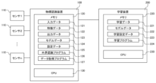
- FIG. 1 is a functional block diagram showing the external environment recognition and learning system according to this embodiment, together with related components such as sensors, a target recognition device, and a learning device.
- the external environment recognition/learning system is broadly composed of one or more (e.g., n: n is a positive integer) sensors 110, a target recognition device 100, and a learning device 200.
- the target recognition device 100 and the learning device 200 are capable of transmitting data at least from the learning device 200 to the target recognition device 100 via an internal bus, an adapter, a wireless communication module, etc.
- the target recognition device 100 and the learning device 200 may be capable of communicating with each other.
- multiple target recognition devices 100 may be connected to the learning device 200.
- the sensor 110 is a sensor that acquires three-dimensional point cloud data relating to the surface shapes of objects (other vehicles, objects, terrain, etc.) in the vicinity of the vehicle (hereinafter sometimes referred to as the host vehicle) on which the target recognition device 100 is mounted, and is, for example, a LiDAR (Laser Imaging Detection and Ranging) sensor.
- the sensor 110 is connected to the target recognition device 100 by wire or wirelessly, and transmits the acquired information to the target recognition device 100.
- the target recognition device 100 has a memory 120 and a CPU (computing unit) 130.
- the memory 120 and the CPU 130 are connected to each other via an internal bus, an adapter, etc.
- Memory 120 is a storage device that stores various programs and information that define the operation of CPU 130.
- the specific programs/information stored in memory 120 are, for example, input data 121, feature data 122, output data 123, model data 124, setting data 125, external environment recognition program 126, and data acquisition program 127.
- the external environment recognition program 126 is a program that recognizes or estimates the meaning of targets (structures, stationary objects, moving objects, signs, marks) and scenes around the vehicle on which the target recognition device 100 is installed, as well as future states.
- the external environment recognition program 126 is configured to execute a series of processes, such as pre-processing, feature extraction processing, area segmentation processing, target recognition processing, output integration processing, and post-processing, which will be described later.
- the external environment recognition program 126 is executed periodically.
- the data acquisition program 127 is a program that converts the information acquired as a signal from the sensor 110 into a specified data format and writes it to memory.
- the input data 121 is measurement data (here, three-dimensional point cloud data) from the sensor 110, and is acquired from the sensor 110 by the data acquisition program 127 and written to an area of the memory 120 allocated for the input data 121.
- Feature data 122 is a feature amount abstracted by feature extraction processing (described later). Note that feature data 122 can also be used as intermediate output of sub-processing (processing of each layer of a neural network, such as a convolutional layer or a fully connected layer) when a neural network (NN) is used for feature extraction processing or target recognition processing (described later).
- sub-processing processing of each layer of a neural network, such as a convolutional layer or a fully connected layer
- NN neural network
- the output data 123 is the output of the calculation results by the external environment recognition program 126, and takes the form of, for example, a bounding box or segmentation information.
- a bounding box is a partial area that surrounds an object (here, a target) in data such as three-dimensional point cloud data, images, or videos, and is made up of information such as the target's position, size, orientation, and target category.
- Segmentation information is target category information for each data point of the input data 121, such as three-dimensional point cloud data.
- the model data 124 is parameter data of the inference model in the target recognition device 100. For example, when feature extraction processing or target recognition processing is performed using a neural network, the weight parameters of each layer correspond to the model data 124.
- the setting data 125 is a setting value that specifies the operation of the external environment recognition program 126 and the data acquisition program 127.
- the learning device 200 has a memory 220 and a CPU (computing device) 230.
- the memory 220 and the CPU 230 are connected to each other via an internal bus, an adapter, etc.
- Memory 220 is a storage device that stores various programs and information that define the operation of CPU 130.
- the specific programs/information stored in memory 120 are exemplified as learning data 221, model data 222, learning setting data 223, and learning program 224.
- the learning program 224 is a program for executing the learning process of the inference model in the target object recognition device 100.
- the learning program 224 is executed periodically.
- the learning data 221 is data used for the learning process of the inference model in the target recognition device 100.
- the learning data 221 for example, data prepared in advance by an experimental or empirical method, or data acquired by the target recognition device 100 is used.
- the model data 222 is parameter data of the inference model in the target object recognition device 100.
- the weight parameters of each layer correspond to the model data 222.
- the learning setting data 223 is hyperparameters such as the learning rate in the learning process.
- the target object recognition device 100 and learning device 200 configured as described above realize functions such as recognition processing of the vehicle's surrounding environment and learning processing by executing programs stored in memories 120 and 220 using the CPUs 130 and 230.
- the actual operating subject of each process by executing a program is the CPU 130 and 230 or an equivalent functional unit (GPU, FPGA, quantum computer, neuromorphic chip, etc.), but for convenience in the following explanation, each processing functional unit realized by the program and task may be described as the subject.
- the external environment recognition processing in the target recognition device 100 we will explain the external environment recognition processing in the target recognition device 100.
- the external environment recognition processing in this embodiment we will show an example of target detection in which vehicles, people, garbage, etc. that exist on the ground are detected as targets (moving objects and stationary objects), and the current or future position of the target is estimated.
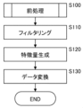
- FIG. 2 is a functional block diagram showing the configuration of the external world recognition processing function realized by the external world recognition program. Also, FIG. 3 is a flowchart showing the flow of the external world recognition processing.
- the external environment recognition processing function is roughly composed of a pre-processing unit 101, a feature extraction processing unit 102, an intermediate feature data region division processing unit 103, a target recognition processing unit 104, an output integration processing unit 105, and a post-processing unit 106.
- the target recognition device 100 performs target recognition processing on the 3D point cloud data input from the sensor 110, in the order of preprocessing by the preprocessing unit 101 (step S100), feature extraction processing by the feature extraction processing unit 102 (step S200), region segmentation processing by the intermediate feature data region segmentation processing unit 103 (step S300), target recognition processing by the target recognition processing unit 104 (step S400), output integration processing by the output integration processing unit 105 (step S500), and post-processing by the post-processing unit 106 (step S600).
- steps S100 to S600 is described in detail below.
- Figure 4 is a flowchart showing the preprocessing process.
- the preprocessing unit 101 first performs filtering as preprocessing (step S110).
- Filtering is a process of extracting and organizing only the necessary parts from the three-dimensional point cloud data obtained by the sensor 110 such as a LiDAR sensor. Specifically, filtering involves removing outliers from the three-dimensional point cloud data and deleting areas that are not to be recognized.
- Feature generation is a process of selecting feature elements for one observation point of the three-dimensional point cloud data and creating a feature vector. Specifically, in feature generation, a feature vector consisting of four elements, X coordinate, Y coordinate, Z coordinate, and reflection intensity, is generated. Note that the feature vector generated in feature generation is not limited to one consisting of only the above four elements, and a feature vector containing additional elements may be generated.
- Data conversion is a process of converting three-dimensional point cloud data from a point cloud data format to another data format, or a process of converting the data structure of point cloud data to another data structure.
- An example of data conversion that converts data formats is a process of converting point cloud data to voxel data.
- Voxel data is a data format in which an observation area is divided into a three-dimensional grid and features are defined for each grid.
- An example of data conversion that converts the data structure of point cloud data to another data structure is a process of converting a data structure in which feature vectors of observation points are arranged in a one-dimensional array into a data structure that uses a tree structure. In this embodiment, the case of conversion to voxel data will be described as an example.
- Figure 5 is a flowchart showing the flow of the feature extraction process.
- the feature extraction processing unit 102 first performs three-dimensional feature extraction as a feature extraction process (step S210).
- Three-dimensional feature extraction is a process of extracting features from the three-dimensional point cloud data converted into voxel data by the pre-processing unit 101 using a sparse three-dimensional convolutional network. Note that in the three-dimensional feature extraction, feature extraction may be performed using, for example, another type of network, depending on the contents of the pre-processing (step S100), etc.
- Feature data generation is a process of converting the output data of the feature extraction process into feature data.
- Examples of feature data include a pseudo image and a target candidate point cloud.
- a pseudo image is a bird's-eye view image of the observation area viewed from above, and has the dimensions of depth, width, and channel.
- a target candidate point cloud is a point set consisting of observation points for a certain target.
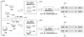
- FIGS. 8 and 9 are diagrams explaining the basic concept of the processing from feature extraction processing to target recognition processing (steps S200 to S400) by the feature extraction processing unit, intermediate feature data region division processing unit, and target recognition processing unit.
- FIG. 8 shows the case where a pseudo image is generated as feature data
- FIG. 9 shows the case where a target candidate point cloud is generated.
- target candidate point clouds 2005, 2006, 2007, and 2008 are point sets consisting of observation points for a certain target, and characteristic points around the target are estimated and the points existing around them are set as target candidate point clouds 2005, 2006, 2007, and 2008.
- the areas occupied by target candidate point clouds 2005, 2006, 2007, and 2008 are set as target area candidates 2001, 2002, 2003, and 2004. Note that when there are multiple targets, an array consisting of target candidate point clouds for each target is generated.
- Figure 6 is a flowchart showing the flow of the area division process.
- the intermediate feature data region division processing unit 103 first reads the region division setting (step S310) as the region division process for dividing the feature data output from the feature extraction processing unit 102 into a plurality of regions.
- the region division setting the number of region divisions, the region division method, the region boundary setting value, etc. are read from the setting data 125 in the memory 120 as the region division setting.
- the region division method is "division by concentric distance centered on the vehicle”
- the region boundary setting value may be determined and adjusted with reference to the density of the point cloud, etc., so that the features of the target at the boundary between two adjacent regions are not separated in the region-divided feature data input to the subsequent processing of the region division process (step S300).
- step S310 After the processing of step S310 is completed, the feature data is divided based on the region division setting, that is, feature data corresponding to each of the first region to the Nth region is extracted from the feature data output from the feature extraction processing unit 102 (steps S320 to S340).
- the processing loop of steps S320 to S340 extracts the feature data corresponding to the first region to the Nth region, and writes it to the region of memory 120 allocated for feature data 122.
- the region from the vehicle 1000 i.e., the LiDAR sensor: sensor 110
- the region from 97 m to 250 m is defined as a second region 1002, 2010, and pixels corresponding to each region are extracted.
- the region from 97 m to 103 m is an overlap region 1003, 2015 where the first region 1001, 2009 and the second region 1002, 2010 overlap.
- the region boundary setting value is a condition that is determined in advance according to the characteristics of the density of the point cloud data in order to divide the feature data into multiple regions.
- the measurement density of point cloud data decreases the farther away from the LiDAR sensor, and less point cloud data is acquired, so even when measuring the same target, the shape of the point cloud data differs greatly between nearby and distant targets.
- the target features indicated by the point cloud data become poorer, resulting in reduced target detection accuracy. Therefore, the relationship between the distance between the LiDAR sensor and the target and the density of the point cloud data is obtained experimentally and empirically, and the region boundary setting value is determined based on this.
- the region boundary setting values are sequentially determined and adjusted with reference to the density of the acquired point cloud data, i.e., when performing dynamic region division processing, the values are set so that the average score for targets existing in each region differs by at least one digit.
- the characteristics indicated by the feature data differ significantly between a single-digit score and a double-digit score, it is conceivable to set the region boundary setting values so as to divide the region into those with a score of 10 or more and those with a score of less than 10.
- the target candidate point clouds 2005, 2006, 2007, and 2008 are each assigned to belong to the region in which their center of gravity exists.
- the target candidate point clouds 2005 and 2007 are assigned to the target candidate point cloud 2009 in the first region
- the target candidate point clouds 2006 and 2008 are assigned to the target candidate point cloud 2010 in the second region.
- Figure 7 is a flowchart showing the flow of the target recognition process.
- the target recognition processing unit 104 first reads the region division settings (step S410) as the target recognition process for detecting targets from feature data divided into multiple regions by the intermediate feature data region division processing unit 103.
- the region division settings the number of region divisions, region division method, region boundary setting value, etc. are read as the region division settings from the setting data 125 in the memory 120, similar to the process of step S310.
- target detection is performed for each of the feature data of the first to Nth regions based on the region division settings (steps S420 to S440).
- the target recognition processing unit 104 defines multiple processing units that realize processing corresponding to each region of the feature data based on the setting data 125, and detects targets for each region of the feature data in each of the multiple processing units.
- models such as FNN (Feedforward Neural Network), RCNN (Regions with Convolutional Neural Network), and SSD (Single Shot multibox Detector) are used to detect targets, and bounding boxes 1005, 1006, 1007, and 1008 indicating the detected targets are output (see Figure 8). Note that the bounding boxes output may be estimates of the future positions of the targets.
- targets are detected for each target region candidate point cloud using a point cloud processing NN (such as Point Net++), and bounding boxes 2011, 2012, 2013, and 2014 indicating the detected targets are output (see FIG. 9).
- the bounding boxes output may be estimates of the future positions of the targets.
- the output integration processing unit 105 performs output integration processing (step S500) by integrating the output of the target recognition processing for each region in the target recognition processing unit 104.
- the output of the target recognition processing in the target recognition processing unit 104 is an array whose elements are bounding boxes that are the results of the target recognition processing. That is, as the output integration processing, the output integration processing unit 105 integrates the arrays of bounding boxes corresponding to each region and outputs an array that brings together the bounding boxes of all regions. Note that in the integrated result that is the output of the output integration processing unit 105, the overlapping parts of the regions have the results of the target recognition processing for each region duplicated.
- the post-processing unit 106 performs thinning of the bounding boxes of the targets using NMS (Non-max suppression) on the integration results output from the output integration processing unit 105.
- NMS Non-max suppression
- the output of the post-processing unit 106 i.e., the result of thinning the integration results of the output integration processing unit 105, is written as the output of the calculation result by the external environment recognition program 126 in an area allocated for the output data 123 of the memory 120.
- FIG. 10 is a flowchart showing the flow of the learning process implemented by the learning program of the learning device.
- the learning process is a process for carrying out learning of the NN model used in the target recognition process of the target recognition device 100.
- the learning device 200 first performs batch data loading and forward propagation, loading the data set to be used for learning into the memory 220 (step T100).
- the target recognition processing unit 104 performs target recognition processing and backpropagation for each region, and calculates the error for each layer (step T200).
- the error for the output layer is calculated using the output data of the target recognition processing for each region and the teacher data.
- error combination is performed to combine the errors calculated for each region of the output data of the target recognition processing unit 104 in step T200 (step T300).
- the error in the first region processing unit 104a of the target recognition processing unit 104 is embedded
- the error in the second region processing unit 104b of the target recognition processing unit 104 is embedded
- the average of the errors in the first and second regions is embedded.
- step T400 backpropagation is performed using the error combined in step T300 (combined error) to calculate the error of the layers that make up the feature extraction processing unit 102 (step T400).
- the gradient is calculated from the error obtained in steps T200 to T400, and the parameters are updated (step T500).
- step T600 it is monitored whether the error and accuracy for the teacher data satisfy a predetermined termination condition, i.e., whether the termination condition is met (step T600). If the result of the determination is NO, i.e., if the termination condition is not met, the processing of steps T100 to T600 is repeated until the termination condition is met. Also, if the result of the determination in step S600 is YES, i.e., if the termination condition is met, the learning process is terminated.
- a predetermined termination condition i.e., whether the termination condition is met
- the measurement density of point cloud data detected by a LiDAR sensor decreases the further away from the LiDAR sensor, and the less point cloud data is acquired. Therefore, even when measuring similar targets, the shape of the point cloud data differs significantly between nearby and distant targets. In other words, because there is less point cloud data for distant targets, the target features indicated by the point cloud data become poorer, resulting in reduced target detection accuracy. In such cases, in the target classification process, targets may be mistakenly recognized as noise, resulting in non-detection, or noise may be mistakenly recognized as targets, resulting in overdetection. Furthermore, using multiple DNN networks to suppress the decrease in detection accuracy for distant targets may result in a decrease in processing speed and increased memory consumption due to an increase in the amount of calculations.
- the target recognition device 100 detects targets from point cloud data having three-dimensional information, and is configured to include a feature extraction processing unit 102 that extracts feature data relating to the shape of the target from the point cloud data, an intermediate feature data region division processing unit 103 that divides the feature data into multiple regions based on predetermined conditions according to the density characteristics of the point cloud data, and a target recognition processing unit 104 that acquires at least information on the target position, size, and type from each of the feature data divided into the multiple regions.
- a feature extraction processing unit 102 that extracts feature data relating to the shape of the target from the point cloud data
- an intermediate feature data region division processing unit 103 that divides the feature data into multiple regions based on predetermined conditions according to the density characteristics of the point cloud data
- a target recognition processing unit 104 that acquires at least information on the target position, size, and type from each of the feature data divided into the multiple regions.
- the target recognition process is configured to be performed for each divided region, even if the vehicle is of the same class, it appears to the feature extraction layer as a separate class for each region, eliminating the need to project point clouds with significantly different shapes into the same region in feature space. Therefore, learning can be carried out so that targets are projected in each region into separate regions in feature space, making optimization easier. Furthermore, because the complexity of the problem to be solved is reduced and learning becomes easier, it is also possible to reduce the number of parameters in the feature extraction processing unit 102 more than would otherwise be the case, leading to further improvements in calculation speed.
- the feature extraction processing unit 102 is shared by the divided regions, it is compatible with processing that extracts global features across the entire observation space, and the problem of being unable to use information outside the region that occurs when a feature extraction processing unit is provided for each divided region does not occur.
- processing that captures global features e.g., Attention, GNN (Graph Neural Network), etc.
- GNN Graph Neural Network
- the errors of each region are integrated by error combination, and the errors are used to learn the features of the feature extraction process of the feature extraction processing unit 102. This makes it possible to efficiently learn the features of multiple regions even with only one feature extraction processing unit 102.
- the overlapping area may be changed between learning and inference. By making the overlapping area larger during learning than during inference, it is possible to learn the characteristics common to each area more efficiently.
- This embodiment shows a case where the settings read in the area division settings reading (step S310) are changed depending on the situation in the area division process (see step S300 in FIG. 3) of the intermediate feature data area division processing unit 103 realized by the external environment recognition program 126 of the first embodiment (see FIG. 2, etc.).
- FIG. 11 is a flowchart showing the flow of the area division process according to this embodiment.
- FIG. 12 is an area division setting table showing the relationship between a number of different situations and the area division settings corresponding to them.
- the intermediate feature data region division processing unit 103 performs region division processing (step S300) to divide the feature data output from the feature extraction processing unit 102 into multiple regions.
- the situation information is determined from several conditions such as the weather, road conditions, and traffic volume around the vehicle, and multiple situations are set in advance according to the conditions. For example, a situation with heavy traffic on a highway is set as "Situation 1,” a situation with medium traffic volume on a highway is set as “Situation 2,” and a situation with light traffic volume on a highway is set as "Situation 3.”
- the corresponding setting (area division setting) is selected from a predetermined division area setting table according to the acquired situation information and read (step S310).
- the area division setting table specifies area division settings corresponding to the situation information. For example, if the situation information acquired in step S301 is "Situation 1", the number of area divisions, area division method, area boundary setting value, etc. stored as "Setting 1" of the area division setting in the setting data 125 of the memory 120 are read.
- the state of the point cloud data acquired for a target varies not only depending on the distance from the LiDAR sensor to the target, but also due to factors such as occlusion.
- occlusion For example, in conditions of heavy traffic, distant vehicles are largely hidden by the shadows of vehicles and obstacles in front of them, and the number of observed point cloud data points is extremely small.
- a relatively large number of points are observed even for distant vehicles.
- target recognition processing can be performed more accurately and efficiently.
- step S310 After the processing of step S310 is completed, the feature data is divided based on the region division setting, that is, feature data corresponding to each of the first region to the Nth region is extracted from the feature data output from the feature extraction processing unit 102 (steps S320 to S340).
- the processing loop of steps S320 to S340 extracts the feature data corresponding to the first region to the Nth region, and writes it to the region of memory 120 allocated for feature data 122.
- the present embodiment configured as described above, can achieve the same effects as the first embodiment.
- this embodiment is configured to perform dynamic area division processing that changes area division settings (particularly area boundary setting values) according to the situation around the vehicle, making it possible to perform target recognition processing with greater accuracy and efficiency.
- This embodiment shows a case where target area candidates are derived and areas are divided according to their features in the area division process (see step S300 in FIG. 3) of the intermediate feature data area division processing unit 103 implemented by the external environment recognition program 126 of the first embodiment (see FIG. 2, etc.).
- FIG. 13 is a flowchart showing the flow of the region segmentation process according to this embodiment.
- FIG. 14 is a diagram explaining the basic concept of the process (steps S200 to S400) from the feature extraction process by the feature extraction processing unit, intermediate feature data region segmentation processing unit, and target recognition processing unit.
- the intermediate feature data region division processing unit 103 performs region division processing to divide the feature data output from the feature extraction processing unit 102 into multiple regions, and first derives provisional target region candidates (step S302).
- the target region candidates 2001, 2004, 3002, and 3003 are the surrounding regions of the anchor box and the representative point, etc.
- step S302 feature extraction is performed to extract the target candidate point clouds 2005, 2008, 3006, and 3007 inside each of the target area candidates 2001, 2004, 3002, and 3003, and each of the target area candidates 2001, 2004, 3002, and 3003 is grouped into multiple groups based on feature quantities such as the number of points (step S303).
- the grouping conditions for the target area candidates 2001, 2004, 3002, and 3003 are, for example, grouping target area candidates with 10 or more points into a first target area candidate point cloud 2009, and target area candidates with fewer than 10 points into a second target area candidate point cloud 2010.
- step S303 After the processing of step S303 is completed, feature data corresponding to each of the first to Nth regions is extracted from the feature data output from the feature extraction processing unit 102 (steps S320 to S340).
- the processing loop of steps S320 to S340 extracts the feature data corresponding to the first to Nth regions, and writes them to the region of memory 120 allocated for feature data 122.
- the present embodiment configured as described above, can achieve the same effects as the first embodiment. In addition, it can achieve more advanced dynamic region segmentation processing, improving target detection accuracy.
- This embodiment shows a case where region boundary estimation processing is performed to estimate the division boundary setting value of the region division setting in the region division processing (see step S300 in FIG. 3) of the intermediate feature data region division processing unit 103 realized by the external environment recognition program 126 of the first embodiment (see FIG. 2, etc.).
- FIG. 15 is a flowchart showing the flow of the area division process according to this embodiment.
- the intermediate feature data region division processing unit 103 performs region division processing to divide the feature data output from the feature extraction processing unit 102 as an image or pseudo image into multiple regions.
- the intermediate feature data region division processing unit 103 performs a region division boundary estimation process to obtain a division boundary setting value for each region from the image or pseudo image using a region division boundary estimation model (step S304).
- Region division boundary estimation models used in the region division boundary estimation process include, for example, a segmentation model and a regression model.
- a segmentation model that can also estimate region division boundary a pseudo image is input as feature data and it is estimated which region each pixel belongs to.
- a regression model as the region division boundary estimation model, an image is input as feature data and a boundary curve is regressed.
- step S304 the feature data is divided based on the division boundary setting value, that is, feature data corresponding to each of the first to Nth regions is extracted from the feature data output from the feature extraction processing unit 102 (steps S320 to S340).
- the processing loop of steps S320 to S340 extracts the feature data corresponding to the first to Nth regions, and writes them to the region of memory 120 allocated for feature data 122.
- the first embodiment configured as described above can also achieve the same effects as the first embodiment.
- dynamic region segmentation processing is performed in which region segmentation boundaries are dynamically determined by a learning model, making it possible to automatically optimize the segmentation boundaries and change the regions to suit the scene, thereby further improving target detection accuracy.
- This embodiment shows a case where the settings read in the area division setting reading (step S310) in the area division process (see step S300 in FIG. 3) of the intermediate feature data area division processing unit 103, which is realized by the external environment recognition program 126 of the first embodiment (see FIG. 2, etc.), are changed according to the lane layout situation around the vehicle.
- FIG. 16 is a flowchart showing the flow of the area division process according to this embodiment.
- the intermediate feature data region division processing unit 103 performs region division processing to divide the feature data output from the feature extraction processing unit 102 as an image or pseudo image into multiple regions.
- the intermediate feature data region division processing unit 103 acquires lane information from a LiDAR sensor, a camera, map data, etc. (step S305).
- step S310 the area division setting is then determined according to the acquired lane information (step S310). Specifically, based on the lane information, it is determined that the lane of the vehicle is the first area and the opposite lane is the second area.
- step S310 After the processing of step S310 is completed, the feature data is divided based on the region division setting (particularly the division boundary setting value), that is, feature data corresponding to each of the first region to the Nth region is extracted from the feature data output from the feature extraction processing unit 102 (steps S320 to S340).
- the processing loop of steps S320 to S340 extracts the feature data corresponding to the first region to the Nth region, and writes it to the region of memory 120 allocated for feature data 122.
- the first embodiment configured as described above can also achieve the same effects as the first embodiment.
- targets can be detected without being confused by differences in characteristics between lanes or between the front, rear, left and right, further improving target detection accuracy. For example, if the vehicle's lane and the opposing lane are separated by an obstacle such as a roadside tree, the vehicle traveling in the opposing lane will be hidden in the shadow of the obstacle, resulting in fewer points in the point cloud data and significantly different characteristics; however, even in such cases, targets can be detected appropriately.
- an obstacle such as a roadside tree
- This embodiment shows a case where, in the region division process (see step S400 in FIG. 3) of the target recognition processing unit 104 implemented by the external environment recognition program 126 of the first embodiment (see FIG. 2, etc.), additional target recognition processing is executed depending on the reliability of the target recognition processing in each region.
- FIG. 17 is a flowchart showing the flow of the target recognition process according to this embodiment.
- the target recognition processing unit 104 first reads the region division settings (step S410) as the target recognition process for detecting targets from feature data divided into multiple regions by the intermediate feature data region division processing unit 103.
- the region division settings the number of region divisions, region division method, region boundary setting value, etc. are read as the region division settings from the setting data 125 in the memory 120, similar to the process of step S310.
- a determination criterion for step S422 for example, it can be determined that additional target detection (second stage) is required when the region to be subjected to target detection is a distant region (such as the second region in Figure 8) where there tends to be less target point cloud data.
- step S422 If the determination result in step S422 is YES, i.e., if the reliability of the target detection (first stage) is estimated to be lower than a predetermined standard, target detection (second stage) is additionally executed (step S423), and the processing loop for the nth region is terminated (step S440).
- target detection process (second stage) of step S423 the bounding box output in the target detection (first stage) for the nth region is treated as a new target candidate region, and a correction amount for the bounding box output in the target detection process (first stage) for the nth region is calculated from the feature amounts around the target region candidate.
- step S440 the process for the nth region ends (step S440).
- Two types of target detection models using the measurement results of a LiDAR sensor are known, for example, the Single Stage Detector and the Second Stage Detector.
- the Second Stage Detector performs target detection processing to correct the results.
- the former has a lower processing load than the latter and can detect targets quickly, but tends to be less accurate. In other words, the latter has higher accuracy than the former, but tends to have a higher processing load and slower target detection.
- additional target detection (second stage) only in specific areas where the reliability of the target detection result is considered to be lower, it is possible to improve the accuracy of the target detection process while reducing the processing load.
- additional target detection is performed only in distant areas where the reliability of target detection is considered to be low; in other words, additional target detection (second stage) is performed only in distant areas where the point cloud density of the point cloud data is low and the amount of data is small, so that it is possible to improve the accuracy of the target detection process while suppressing an increase in the processing load.
- the present embodiment configured as described above, can achieve the same effects as the first embodiment.
- This embodiment shows a case where, in the pre-processing (see step S100 in FIG. 3) of the pre-processing unit 101 implemented by the external environment recognition program 126 of the first embodiment (see FIG. 2, etc.), when the sensor 110 is a device for acquiring images such as a stereo camera and the measurement data input to the target recognition device is image data, additional processing of 3D coordinate changes of the camera image is performed after filtering (step S110).
- FIG. 18 is a flowchart showing the flow of pre-processing according to this embodiment.
- the preprocessing unit 101 first performs filtering as preprocessing (step S110).
- Filtering is a process of extracting and organizing only the necessary parts from the camera image (image data) obtained by the sensor 110 such as a stereo camera. Specifically, filtering involves removing outliers from the image data and deleting areas that are not to be recognized.
- step S111 the camera image is then subjected to 3D coordinate conversion (step S111) in which the distance from the sensor 110 to the target (in other words, the X coordinate, Y coordinate, and Z coordinate) is calculated for each pixel using the parallax information related to the camera image.
- the same processing as for point cloud data can be performed in the subsequent processing.
- Feature generation is a process of selecting feature elements for one observation point of the three-dimensional point cloud data and creating a feature vector. Specifically, in feature generation, a feature vector consisting of elements of the X coordinate, Y coordinate, Z coordinate, reflection intensity, and RGB values of the image is generated. Note that the feature vector generated in feature generation is not limited to being composed of only the above elements, and a feature vector that includes additional elements may be generated.
- step S130 data conversion is then performed (step S130).
- Data conversion is a process of converting the three-dimensional point cloud data from a point cloud data format to another data format, or a process of converting the data structure of the point cloud data to another data structure.
- the present embodiment configured as described above, can achieve the same effects as the first embodiment.
- the senor 110 Even if a device that acquires camera images, such as a stereo camera, is used as the sensor 110, it is possible to suppress decreases in processing speed and increases in memory consumption, thereby achieving high-speed processing and memory savings while detecting nearby and distant targets with greater accuracy.
- This embodiment shows a case in which, in the pre-processing (see step S100 in FIG. 3) of the pre-processing unit 101 implemented by the external environment recognition program 126 of the first embodiment (see FIG. 2, etc.), when the sensor 110 is a device that acquires radar data, such as a radar, and the measurement data input to the target recognition device is radar data, additional processing of 3D coordinate changes of the radar data is performed after filtering (step S110).
- FIG. 19 is a flowchart showing the pre-processing procedure according to this embodiment.
- the preprocessing unit 101 first performs filtering as preprocessing (step S110).
- Filtering is a process of extracting and organizing only the necessary parts from radar data (waveform data of waves reflected from targets) obtained by a sensor 110 such as a radar. Specifically, filtering involves removing outliers from the radar data and deleting areas that are not to be recognized.
- step S112 3D coordinate conversion of the radar data (waveform data of the reflected waves from the target) is performed (step S112) to convert the radar data into the distance from the sensor 110 to the target (in other words, the X coordinate, Y coordinate, and Z coordinate).
- the radar data is converted into 3D coordinates in this way, the same processing as for point cloud data can be performed in the subsequent processing.
- Feature generation is a process of selecting feature elements for one observation point of the three-dimensional point cloud data and creating a feature vector. Specifically, in feature generation, a feature vector consisting of four elements, X coordinate, Y coordinate, Z coordinate, and reflection intensity, is generated. Note that the feature vector generated in feature generation is not limited to one consisting of only the above four elements, and a feature vector containing additional elements may be generated.
- step S130 data conversion is then performed (step S130).
- Data conversion is a process of converting the three-dimensional point cloud data from a point cloud data format to another data format, or a process of converting the data structure of the point cloud data to another data structure.
- the present embodiment configured as described above, can achieve the same effects as the first embodiment.
- This embodiment shows a case where three-dimensional point cloud data obtained from a LiDAR sensor or the like and image data obtained from a camera or the like are fused and used in the preprocessing (see step S100 in FIG. 3) of the preprocessing unit 101 realized by the external environment recognition program 126 of the first embodiment (see FIG. 2, etc.).
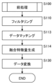
- FIG. 20 is a flowchart showing the flow of pre-processing according to this embodiment.
- the preprocessing unit 101 first performs filtering as preprocessing (step S110).
- Filtering is a process of extracting and organizing only the necessary parts from three-dimensional point cloud data obtained by a LiDAR sensor or the like and image data obtained by a camera or the like. Specifically, filtering involves removing outliers from the three-dimensional point cloud data and image data, deleting areas that are not to be recognized, etc.
- step S110 the coordinates of the 3D point cloud data are converted to camera coordinates and projected onto the image plane of the camera, and data matching is performed to match the pixels of the camera image (step S113).
- step S114 fusion feature generation is performed (step S114).
- fusion feature generation the pixels matched in the processing of step S113 are assigned to the 3D point cloud data, and a feature vector consisting of elements of X coordinate, Y coordinate, Z coordinate, reflection intensity, and RGB values of the image is generated.
- the feature vector generated in fusion feature generation is not limited to being composed of only the above elements, and a feature vector containing additional elements may be generated.
- step S130 Data conversion is a process of converting the three-dimensional point cloud data from a point cloud data format to another data format, or a process of converting the data structure of the point cloud data to another data structure.
- the present embodiment configured as described above, can achieve the same effects as the first embodiment.
- target recognition processing is performed by fusing data obtained from multiple types of sensors, making it possible to detect targets more accurately than when a single sensor is used.
- This embodiment shows a case where sensor data obtained from a plurality of sensors 110 (same type or different types) is fused and used in the feature extraction process (see step S200 in FIG. 3) of the feature extraction processing unit 102 realized by the external environment recognition program 126 of the first embodiment (see FIG. 2, etc.). Note that in this embodiment, an example will be described in which sensor data obtained from two sensors is fused.
- FIG. 21 is a flowchart showing the flow of feature extraction processing according to this embodiment.
- the feature extraction processing unit 102 performs feature extraction processing by first extracting first feature data from data obtained from one of the multiple sensors (here, first sensor data obtained from one of the two sensors) using a corresponding first feature extraction model (step S211), and in parallel extracting second feature data from data obtained from the other of the multiple sensors (here, second sensor data obtained from the other of the two sensors) using a corresponding second feature extraction model (step S212).
- the points of the first feature data and the second feature data are matched to generate third feature data (step S213).
- the points of the first feature data and the points of the second feature data are elements that make up feature data, such as points, pixels, voxels, etc.
- step S220 feature data generation is then performed (step S220).
- Feature data generation is a process of converting the output data of the feature extraction processing into feature data.
- the present embodiment configured as described above, can achieve the same effects as the first embodiment.
- the disadvantages of one sensor can be covered by the advantages of the other sensors, enabling more accurate target recognition processing. That is, for example, by fusing data obtained from multiple sensors, including different types, to perform target detection, the disadvantages of one type of sensor can be covered by other types of sensors. Even when performing target detection by fusing data obtained from multiple sensors of the same type, the disadvantages of one sensor due to differences in the sensor installation position, installation environment, etc. can be covered by the other sensors.
- This embodiment shows a case where targets in each area are estimated in the target recognition process (see step S400 in FIG. 3) of the target recognition processing unit 104, which is realized by the external environment recognition program 126 of the first embodiment (see FIG. 2, etc.).
- FIG. 22 is a flowchart showing the flow of the target recognition process according to this embodiment.
- the target recognition processing unit 104 first reads the region division settings (step S410) as the target recognition process for detecting targets from feature data divided into multiple regions by the intermediate feature data region division processing unit 103.
- the region division settings the number of region divisions, region division method, region boundary setting values, etc. are read as the region division settings from the setting data 125 in the memory 120.
- step S410 After the processing of step S410 is completed, a segmentation process is then performed for each of the first through Nth regions based on the region division settings, in which vehicles, pedestrians, obstacles, as well as drivable road surfaces and white lines, are recognized based on the features of each region (steps S420, S431, S440). Segmentation is a process of classifying points, voxels, or pixels, and estimating what types of targets are distributed in which regions of the observation region.
- the present embodiment configured as described above, can achieve the same effects as the first embodiment.
- Twelfth embodiment A twelfth embodiment of the present invention will be described with reference to FIG.
- This embodiment shows a case where spatial feature extraction and time series feature extraction are performed in the feature extraction process (see step S200 in FIG. 3) of the feature extraction processing unit 102 realized by the external environment recognition program 126 of the first embodiment (see FIG. 2, etc.).
- FIG. 23 is a flowchart showing the flow of feature extraction processing according to this embodiment.
- the feature extraction processing unit 102 performs feature extraction by first performing spatial feature extraction to extract spatial features (step S214), and then performing time-series feature extraction to capture time-series changes (step S215).
- step S220 feature data generation is then performed (step S220).
- Feature data generation is a process of converting the output data of the feature extraction processing into feature data.
- the present embodiment configured as described above, can achieve the same effects as the first embodiment.
- the feature extraction process is configured to capture time-series changes in addition to spatial feature extraction, so it can handle cases where targets, such as other vehicles, move to different areas over time, improving the accuracy of target recognition in a single frame.
- FIG. 24 is a flowchart showing the flow of the learning process according to this embodiment.
- the learning device 200 first learns the entire model using all-domain data, i.e., learns the entire domain (step T101). Specifically, for example, the learning process shown in the first embodiment (see FIG. 10), i.e., learning of the NN model used in the target recognition process of the target recognition device 100, is performed.
- step T102 determines whether the result of the determination in step T102 is YES, or if the processing in step T103 is completed.
- the present embodiment configured as described above, can achieve the same effects as the first embodiment.
- the parameters constituting the feature extraction processing unit 102 of the target recognition device 100 are divided into parameters for extracting the features of targets in the first region, parameters for extracting the features of targets in the second region, and parameters for extracting the features of common targets.
- the present invention is not limited to the above-described embodiment, and includes various modifications and combinations that do not deviate from the gist of the present invention. Furthermore, the present invention is not limited to those having all of the configurations described in the above-described embodiment, and includes those in which some of the configurations are omitted.
Landscapes
- Engineering & Computer Science (AREA)
- Physics & Mathematics (AREA)
- General Physics & Mathematics (AREA)
- Remote Sensing (AREA)
- Radar, Positioning & Navigation (AREA)
- Computer Networks & Wireless Communication (AREA)
- Electromagnetism (AREA)
- Chemical & Material Sciences (AREA)
- Analytical Chemistry (AREA)
- Multimedia (AREA)
- Theoretical Computer Science (AREA)
- Artificial Intelligence (AREA)
- Evolutionary Computation (AREA)
- Image Analysis (AREA)
Priority Applications (3)
| Application Number | Priority Date | Filing Date | Title |
|---|---|---|---|
| PCT/JP2023/007499 WO2024180708A1 (ja) | 2023-03-01 | 2023-03-01 | 物標認識装置及び物標認識方法 |
| DE112023005588.2T DE112023005588T5 (de) | 2023-03-01 | 2023-03-01 | Zielerkennungseinrichtung und zielerkennungsverfahren |
| JP2025503499A JPWO2024180708A1 (https=) | 2023-03-01 | 2023-03-01 |
Applications Claiming Priority (1)
| Application Number | Priority Date | Filing Date | Title |
|---|---|---|---|
| PCT/JP2023/007499 WO2024180708A1 (ja) | 2023-03-01 | 2023-03-01 | 物標認識装置及び物標認識方法 |
Publications (1)
| Publication Number | Publication Date |
|---|---|
| WO2024180708A1 true WO2024180708A1 (ja) | 2024-09-06 |
Family
ID=92589384
Family Applications (1)
| Application Number | Title | Priority Date | Filing Date |
|---|---|---|---|
| PCT/JP2023/007499 Ceased WO2024180708A1 (ja) | 2023-03-01 | 2023-03-01 | 物標認識装置及び物標認識方法 |
Country Status (3)
| Country | Link |
|---|---|
| JP (1) | JPWO2024180708A1 (https=) |
| DE (1) | DE112023005588T5 (https=) |
| WO (1) | WO2024180708A1 (https=) |
Citations (4)
| Publication number | Priority date | Publication date | Assignee | Title |
|---|---|---|---|---|
| JP2012194061A (ja) * | 2011-03-16 | 2012-10-11 | Canon Inc | 三次元距離計測装置、三次元距離計測方法、およびプログラム |
| WO2021016751A1 (zh) * | 2019-07-26 | 2021-02-04 | 深圳市大疆创新科技有限公司 | 一种点云特征点提取方法、点云传感系统及可移动平台 |
| WO2022097365A1 (ja) * | 2020-11-06 | 2022-05-12 | 日立Astemo株式会社 | 外界認識装置、および、外界認識方法 |
| WO2022195929A1 (ja) * | 2021-03-17 | 2022-09-22 | 日立Astemo株式会社 | 物体認識装置 |
-
2023
- 2023-03-01 WO PCT/JP2023/007499 patent/WO2024180708A1/ja not_active Ceased
- 2023-03-01 JP JP2025503499A patent/JPWO2024180708A1/ja active Pending
- 2023-03-01 DE DE112023005588.2T patent/DE112023005588T5/de active Pending
Patent Citations (4)
| Publication number | Priority date | Publication date | Assignee | Title |
|---|---|---|---|---|
| JP2012194061A (ja) * | 2011-03-16 | 2012-10-11 | Canon Inc | 三次元距離計測装置、三次元距離計測方法、およびプログラム |
| WO2021016751A1 (zh) * | 2019-07-26 | 2021-02-04 | 深圳市大疆创新科技有限公司 | 一种点云特征点提取方法、点云传感系统及可移动平台 |
| WO2022097365A1 (ja) * | 2020-11-06 | 2022-05-12 | 日立Astemo株式会社 | 外界認識装置、および、外界認識方法 |
| WO2022195929A1 (ja) * | 2021-03-17 | 2022-09-22 | 日立Astemo株式会社 | 物体認識装置 |
Also Published As
| Publication number | Publication date |
|---|---|
| JPWO2024180708A1 (https=) | 2024-09-06 |
| DE112023005588T5 (de) | 2025-10-30 |
Similar Documents
| Publication | Publication Date | Title |
|---|---|---|
| US11482014B2 (en) | 3D auto-labeling with structural and physical constraints | |
| CN109948661B (zh) | 一种基于多传感器融合的3d车辆检测方法 | |
| CN110588653B (zh) | 自主车辆的控制系统、控制方法以及控制器 | |
| US12189718B1 (en) | Learned state covariances | |
| US11188091B2 (en) | Mesh decimation based on semantic information | |
| US10884428B2 (en) | Mesh decimation techniques and validation | |
| CN116685874A (zh) | 摄像机-激光雷达融合对象检测系统和方法 | |
| US12450918B2 (en) | Automatic lane marking extraction and classification from lidar scans | |
| CN115187964A (zh) | 基于多传感器数据融合的自动驾驶决策方法及SoC芯片 | |
| KR20230070253A (ko) | 포인트 클라우드들로부터의 효율적인 3차원 객체 검출 | |
| US11227401B1 (en) | Multiresolution voxel space | |
| Kanchana et al. | Computer vision for autonomous driving | |
| CN113611008B (zh) | 一种车辆行驶场景采集方法、装置、设备及介质 | |
| CN114802261A (zh) | 泊车控制方法、障碍物识别模型训练方法、装置 | |
| CN111461221A (zh) | 一种面向自动驾驶的多源传感器融合目标检测方法和系统 | |
| JP6601506B2 (ja) | 画像処理装置、物体認識装置、機器制御システム、画像処理方法、画像処理プログラム及び車両 | |
| CN116468950B (zh) | 一种类别引导中心点邻域搜索半径的三维目标检测方法 | |
| CN119600557A (zh) | 用于车辆的道路几何估计 | |
| CN116994225A (zh) | 目标检测方法、装置、计算机设备和存储介质 | |
| Yusuf et al. | Data Fusion of Semantic and Depth Information in the Context of Object Detection | |
| CN116203576A (zh) | 一种基于环境感知的3d目标检测方法及系统 | |
| CN118537835B (zh) | 一种多模态融合知识图谱的交通动态遮挡跟踪方法及系统 | |
| WO2024180708A1 (ja) | 物標認識装置及び物標認識方法 | |
| CN117935209A (zh) | 障碍物检测方法、装置、设备和存储介质 | |
| CN119317946A (zh) | 伪图像中的实例分割 |
Legal Events
| Date | Code | Title | Description |
|---|---|---|---|
| 121 | Ep: the epo has been informed by wipo that ep was designated in this application |
Ref document number: 23925265 Country of ref document: EP Kind code of ref document: A1 |
|
| ENP | Entry into the national phase |
Ref document number: 2025503499 Country of ref document: JP Kind code of ref document: A |
|
| WWE | Wipo information: entry into national phase |
Ref document number: 2025503499 Country of ref document: JP |
|
| WWE | Wipo information: entry into national phase |
Ref document number: 112023005588 Country of ref document: DE |
|
| WWP | Wipo information: published in national office |
Ref document number: 112023005588 Country of ref document: DE |
|
| 122 | Ep: pct application non-entry in european phase |
Ref document number: 23925265 Country of ref document: EP Kind code of ref document: A1 |