WO2024176644A1 - インピーダンスパラメータ計測方法、およびインピーダンスパラメータ計測装置 - Google Patents
インピーダンスパラメータ計測方法、およびインピーダンスパラメータ計測装置 Download PDFInfo
- Publication number
- WO2024176644A1 WO2024176644A1 PCT/JP2024/000571 JP2024000571W WO2024176644A1 WO 2024176644 A1 WO2024176644 A1 WO 2024176644A1 JP 2024000571 W JP2024000571 W JP 2024000571W WO 2024176644 A1 WO2024176644 A1 WO 2024176644A1
- Authority
- WO
- WIPO (PCT)
- Prior art keywords
- constant
- electrochemical device
- voltage
- cpe
- measurement
- Prior art date
- Legal status (The legal status is an assumption and is not a legal conclusion. Google has not performed a legal analysis and makes no representation as to the accuracy of the status listed.)
- Ceased
Links
Images






Classifications
-
- G—PHYSICS
- G01—MEASURING; TESTING
- G01R—MEASURING ELECTRIC VARIABLES; MEASURING MAGNETIC VARIABLES
- G01R31/00—Arrangements for testing electric properties; Arrangements for locating electric faults; Arrangements for electrical testing characterised by what is being tested not provided for elsewhere
- G01R31/36—Arrangements for testing, measuring or monitoring the electrical condition of accumulators or electric batteries, e.g. capacity or state of charge [SoC]
- G01R31/389—Measuring internal impedance, internal conductance or related variables
-
- G—PHYSICS
- G01—MEASURING; TESTING
- G01R—MEASURING ELECTRIC VARIABLES; MEASURING MAGNETIC VARIABLES
- G01R27/00—Arrangements for measuring resistance, reactance, impedance, or electric characteristics derived therefrom
- G01R27/02—Measuring real or complex resistance, reactance, impedance, or other two-pole characteristics derived therefrom, e.g. time constant
-
- G—PHYSICS
- G01—MEASURING; TESTING
- G01R—MEASURING ELECTRIC VARIABLES; MEASURING MAGNETIC VARIABLES
- G01R31/00—Arrangements for testing electric properties; Arrangements for locating electric faults; Arrangements for electrical testing characterised by what is being tested not provided for elsewhere
- G01R31/36—Arrangements for testing, measuring or monitoring the electrical condition of accumulators or electric batteries, e.g. capacity or state of charge [SoC]
- G01R31/3644—Constructional arrangements
- G01R31/3648—Constructional arrangements comprising digital calculation means, e.g. for performing an algorithm
-
- G—PHYSICS
- G01—MEASURING; TESTING
- G01R—MEASURING ELECTRIC VARIABLES; MEASURING MAGNETIC VARIABLES
- G01R31/00—Arrangements for testing electric properties; Arrangements for locating electric faults; Arrangements for electrical testing characterised by what is being tested not provided for elsewhere
- G01R31/36—Arrangements for testing, measuring or monitoring the electrical condition of accumulators or electric batteries, e.g. capacity or state of charge [SoC]
- G01R31/367—Software therefor, e.g. for battery testing using modelling or look-up tables
-
- G—PHYSICS
- G01—MEASURING; TESTING
- G01R—MEASURING ELECTRIC VARIABLES; MEASURING MAGNETIC VARIABLES
- G01R31/00—Arrangements for testing electric properties; Arrangements for locating electric faults; Arrangements for electrical testing characterised by what is being tested not provided for elsewhere
- G01R31/36—Arrangements for testing, measuring or monitoring the electrical condition of accumulators or electric batteries, e.g. capacity or state of charge [SoC]
- G01R31/382—Arrangements for monitoring battery or accumulator variables, e.g. SoC
- G01R31/3835—Arrangements for monitoring battery or accumulator variables, e.g. SoC involving only voltage measurements
-
- G—PHYSICS
- G01—MEASURING; TESTING
- G01R—MEASURING ELECTRIC VARIABLES; MEASURING MAGNETIC VARIABLES
- G01R31/00—Arrangements for testing electric properties; Arrangements for locating electric faults; Arrangements for electrical testing characterised by what is being tested not provided for elsewhere
- G01R31/36—Arrangements for testing, measuring or monitoring the electrical condition of accumulators or electric batteries, e.g. capacity or state of charge [SoC]
- G01R31/392—Determining battery ageing or deterioration, e.g. state of health
-
- H—ELECTRICITY
- H01—ELECTRIC ELEMENTS
- H01M—PROCESSES OR MEANS, e.g. BATTERIES, FOR THE DIRECT CONVERSION OF CHEMICAL ENERGY INTO ELECTRICAL ENERGY
- H01M10/00—Secondary cells; Manufacture thereof
- H01M10/42—Methods or arrangements for servicing or maintenance of secondary cells or secondary half-cells
- H01M10/48—Accumulators combined with arrangements for measuring, testing or indicating the condition of cells, e.g. the level or density of the electrolyte
-
- H—ELECTRICITY
- H02—GENERATION; CONVERSION OR DISTRIBUTION OF ELECTRIC POWER
- H02J—ELECTRIC POWER NETWORKS; CIRCUIT ARRANGEMENTS OR SYSTEMS FOR SUPPLYING OR DISTRIBUTING ELECTRIC POWER; SYSTEMS FOR STORING ELECTRIC ENERGY
- H02J7/00—Circuit arrangements for charging or discharging batteries or for supplying loads from batteries
-
- Y—GENERAL TAGGING OF NEW TECHNOLOGICAL DEVELOPMENTS; GENERAL TAGGING OF CROSS-SECTIONAL TECHNOLOGIES SPANNING OVER SEVERAL SECTIONS OF THE IPC; TECHNICAL SUBJECTS COVERED BY FORMER USPC CROSS-REFERENCE ART COLLECTIONS [XRACs] AND DIGESTS
- Y02—TECHNOLOGIES OR APPLICATIONS FOR MITIGATION OR ADAPTATION AGAINST CLIMATE CHANGE
- Y02E—REDUCTION OF GREENHOUSE GAS [GHG] EMISSIONS, RELATED TO ENERGY GENERATION, TRANSMISSION OR DISTRIBUTION
- Y02E60/00—Enabling technologies; Technologies with a potential or indirect contribution to GHG emissions mitigation
- Y02E60/10—Energy storage using batteries
Definitions
- This technology relates to an impedance parameter measurement method and an impedance parameter measurement device.
- the electric double layer capacity of a lithium-ion battery is sometimes described as an electric circuit that includes a CPE (Constant Phase Element).
- a CPE is an element that has two constants: a p constant that represents the characteristics of the element, and a T constant that represents its physical properties. Methods for solving these p constants and T constants in the time domain are disclosed, for example, in Patent Document 1 and Non-Patent Document 1.
- Patent Document 1 and Non-Patent Document 1 have a problem in that a long calculation time is required when calculating the time domain behavior of an electric circuit including a CPE. It is desirable to provide an impedance parameter measurement method and an impedance parameter measurement device that can measure the p constant and T constant while shortening the calculation time.
- An impedance parameter measurement method is a method for measuring impedance parameters of an electrochemical device having an equivalent circuit that is an electric circuit including a CPE (Constant Phase Element), and includes the following three features.
- C deriving a p constant of the CPE based on multiple voltage values obtained by the measurement, and deriving a T constant of the CPE based on the derived p constant and the multiple voltage values obtained by the measurement.
- the impedance parameter measuring device is a device capable of measuring the impedance parameters of an electrochemical device having an equivalent circuit that is an electric circuit including a CPE.
- This impedance parameter measuring device includes a current source, a measurement circuit, and a signal processing unit.
- the current source is capable of applying a step-like current change to the electrochemical device.
- the measurement circuit is capable of measuring the voltage of the electrochemical device at multiple different times while the voltage of the electrochemical device is undergoing a transient response by applying a current change to the electrochemical device.
- the signal processing unit is capable of deriving the p constant of the CPE based on multiple voltage values obtained by measurement, and deriving the T constant of the CPE based on the derived p constant and multiple voltage values obtained by measurement.
- a step-like current change is applied to an electrochemical device having an equivalent circuit of an electric circuit including a CPE, and while the voltage of the electrochemical device is making a transient response, the voltage of the electrochemical device is measured at multiple different times. Then, the p constant of the CPE is derived based on multiple voltage values obtained by the measurement, and the T constant of the CPE is derived based on the derived p constant and multiple voltage values obtained by the measurement. This makes it possible to measure the p constant and T constant while shortening the calculation time.
- FIG. 1 is a diagram illustrating an example of an equivalent circuit of an electrochemical device.
- FIG. 2 is a diagram showing an example of an equation for the voltage response of the equivalent circuit of FIG.
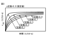
- FIG. 3 is a diagram showing an example of the voltage response of an equivalent circuit derived from the voltage response equation of FIG. 2 on both linear scales.
- FIG. 4 is a diagram showing, on a double logarithmic scale, an example of the voltage response of an equivalent circuit derived from the voltage response equation of FIG.
- FIG. 3 is a diagram showing an example of the voltage response of an equivalent circuit derived from the voltage response equation of FIG. 2 on both linear scales.
- FIG. 4 is a diagram showing, on a double logarithmic scale, an example of the voltage response of an equivalent circuit derived from the voltage response equation of FIG.
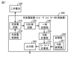
- FIG. 7 is a diagram illustrating a schematic configuration example of a charge/discharge device according to a first embodiment of the present technology.
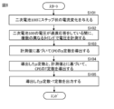
- FIG. 8 is a diagram showing an example of the operation of the charge/discharge device of FIG.
- FIG. 9 is a diagram illustrating a schematic configuration example of an impedance parameter measurement system including a server device according to a second embodiment of the present technology.
- FIG. 10 is a diagram showing an example in which the functions of the temporary storage unit, the gradient calculation unit, and the Z parameter calculation unit in FIG. 7 and FIG. 9 are executed by the control unit.
- the electric double layer capacity of a lithium-ion battery is sometimes described as an electric circuit including a CPE (Constant Phase Element).
- a CPE is an element having two constants, p constant, which represents the characteristics of the element, and T constant, which represents the physical property value.
- the impedance Z CPE in the frequency domain is described by the following formula.
- j is the imaginary unit
- ⁇ is the angular frequency.
- Z CPE 1/ ⁇ T ⁇ (j ⁇ ) p ⁇
- Measuring the p constant and T constant helps distinguish between abnormal lithium-ion batteries that deteriorate in the above-mentioned degradation mode and normal lithium-ion batteries.
- the AC impedance method is used to measure the p constant and T constant. Measurements using the AC impedance method require specialized equipment or circuits such as an FRA (Frequency Response Analyzer). For this reason, it has been difficult from a cost standpoint to install such specialized equipment or circuits in electronic devices equipped with battery modules or in chargers for charging battery modules.
- FRA Frequency Response Analyzer
- a time domain solution for an electric circuit including a CPE is derived using non-integer differentiation (fractional differentiation) rather than integer differentiation such as first or second differentiation.
- a time domain solution for an electric circuit including a CPE is derived using a Laplace transform.
- Patent document JP 2011-145944 ⁇ Non-patent document: Chun-Sing Cheng, Henry Shu-Hung Chung, Ricky Wing-Hong Lau, and Kelvin Yi-Wen Hong, "Time-Domain Modeling of Constant Phase Elements for Simulation of Lithium Battery Behavior," IEEE Transactions on Power Electronics 34(8), 2019, pp 7573-7587.
- both the above patent documents and non-patent documents have a problem in that a long calculation time is required when calculating the time domain behavior of an electric circuit including a CPE.
- the inventors of the present application have focused on this problem and propose below an impedance parameter measurement method and an impedance parameter measurement device that can measure the p constant and T constant while shortening the calculation time.
- FIG. 1 shows an equivalent circuit of an electrochemical device ED.
- the electrochemical device ED is represented by an equivalent circuit including a parallel circuit of a CPE and a resistor (R).
- the electrochemical device ED is, for example, a lithium ion battery (secondary battery), a dye-sensitized solar cell (solar cell), or a fuel cell (electrochemical battery).
- a current source IS is connected to the electrochemical device ED, and a current I generated by the current source IS is supplied to the electrochemical device ED.
- the electrochemical device ED is a lithium ion battery (secondary battery)
- the current I generated by the current source IS is supplied to the electrochemical device ED when the electrochemical device ED is fully charged.
- the current source IS is capable of providing a step-like current change to the electrochemical device ED.
- the current source IS is capable of providing, for example, a step-like current change, a current change with a rising waveform to the electrochemical device ED.
- the current source IS is capable of providing, for example, a step-like current change, a current change with a falling waveform to the electrochemical device ED.
- a transient response occurs in the voltage of the electrochemical device ED.
- This transient response continues for about several tens of ⁇ s, and then converges to a constant value.
- the voltage of the electrochemical device ED is measured at multiple (at least two) different times. If a logarithmic graph of time versus voltage is drawn using the multiple voltage values obtained at this time, a linear graph with a slope of ⁇ is obtained.
- the voltage applied to the CPE in an electric circuit including a parallel circuit of the CPE and a resistor (R) can be expressed, for example, by the voltage response equation shown in FIG. 2 (CSChenge et al., IEEE Trans. on Power Elec.34(8), 2019, 7573-7587.).
- a linear graph of time and voltage ⁇ CPE is drawn using the voltage ⁇ CPE of the CPE obtained by this equation, a curved graph such as that shown in FIG. 3 is obtained.
- FIG. 3 illustrates graphs in which the p constant is fixed to 0.8 and the T constants are 0.1, 0.3, 0.5, 0.7, and 0.9.
- FIG. 4 illustrates graphs in which the p constant is fixed to 0.8 and the T constants are 0.1, 0.3, 0.5, 0.7, and 0.9.
- the slopes of the respective graphs are approximately the same.
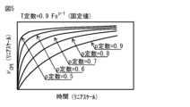
- FIG. 5 shows graphs in which the T constant is fixed to 0.9Fs p-1 and the p constant is 0.5, 0.6, 0.7, 0.8, and 0.9.
- a curved graph such as that shown in FIG. 6 is obtained.
- FIG. 6 shows graphs in which the T constant is fixed to 0.9Fs p-1 and the p constant is 0.5, 0.6, 0.7, 0.8, and 0.9.
- the slopes of the graphs are different from each other in the period before the voltage ⁇ CPE of the CPE converges to a constant value.
- the gradient ⁇ obtained when a step-like current change is applied to the electrochemical device ED coincides with the p constant when the resistance R connected in parallel can be considered to be sufficiently large or when the time change in the voltage ⁇ CPE can be considered to be sufficiently small. This can be explained by the following formula.
- Equation (1) the voltage transient response of a circuit in which CPE and R are connected in parallel can be described by equation (1), where n is the number of steps, T is the step time, C is the T constant of CPE, ⁇ is the p constant of CPE, and i is the current.
- equation (1) can be transformed into equation (2).
- the expression (2) can be transformed into the expression (4).
- Equation (6) is the equation of a straight line.
- p is the slope of the log-log plot, and the two terms on the right-hand side are the intercepts.
- the p constant can be determined from the magnitude of the slope ⁇ obtained when a step-like current change is applied to the electrochemical device ED.
- an apparatus that can derive the p constant using the slope ⁇ obtained when a step-like current change is applied to the electrochemical device ED, and can derive the T constant using the derived p constant. Note that below, we will explain using a lithium ion battery as an example of the electrochemical device ED, but the electrochemical device ED is not limited to a lithium ion battery and may be other devices.
- FIG. 7 illustrates a schematic configuration example of the charging/discharging device 200.
- the charging/discharging device 200 is a device that charges and discharges a secondary battery 100.
- the charging/discharging device 200 corresponds to a specific example of an "impedance parameter measuring device" according to an embodiment of the present technology.
- the charging/discharging device 200 has not only the function of charging and discharging the secondary battery 100, but also the function of measuring the impedance parameters of the secondary battery 100.
- the "impedance parameters of the secondary battery 100" refer to the p constant and T constant of the equivalent circuit when the equivalent circuit of the secondary battery 100 can be expressed as an electric circuit including a parallel circuit of a CPE and a resistor (R).
- the secondary battery 100 is a lithium-ion secondary battery.
- the lithium-ion secondary battery included in the secondary battery 100 may be a unit cell, a battery block in which a number of unit cells are connected, or an assembled battery in which a battery block and accessories are integrally packed. In an assembled battery, a number of lithium-ion secondary batteries are connected in series. The assembled battery may also include a number of lithium-ion secondary batteries electrically connected in parallel.
- the charging/discharging device 200 includes, for example, a charging/discharging circuit 210, a charging/discharging control unit 220, an IV measurement circuit 230, a temporary memory unit 240, a gradient calculation unit 250, a memory unit 260, a Z parameter calculation unit 270, and an output unit 280, as shown in FIG. 7.
- the charge/discharge circuit 210 has a charge circuit for charging the secondary battery 100 and a discharge circuit for discharging the secondary battery 100.
- the charge circuit includes, for example, a generator and a converter.
- the charge/discharge control unit 220 is capable of controlling the current for charging the secondary battery 100 and controlling the current for discharging the secondary battery 100.
- the charge/discharge control unit 220 is, for example, configured with an MPU (Micro-Processing Unit) that performs charge/discharge control, or a CPU (Central Processing Unit) in which a charge/discharge control program is loaded.
- the charge/discharge control unit 220 is capable of controlling the charge/discharge circuit 210 to give a step-like current change to the secondary battery 100.
- the charge/discharge control unit 220 is, for example, capable of controlling the charge/discharge circuit 210 to give a current change with a rising waveform to the secondary battery 100 as a step-like current change.
- the charge/discharge control unit 220 can control the charge/discharge circuit 210 to provide a step-like current change, for example, a falling waveform current change, to the secondary battery 100.
- the charge/discharge circuit 210 is capable of applying a step-like current change to the secondary battery 100 under the control of the charge/discharge control unit 220.
- the charge/discharge circuit 210 is capable of applying a step-like current change, that is, a current change with a rising waveform, to the secondary battery 100 under the control of the charge/discharge control unit 220.
- the charge/discharge circuit 210 is capable of applying a step-like current change, that is, a current change with a falling waveform, to the secondary battery 100 under the control of the charge/discharge control unit 220.
- the IV measurement circuit 230 includes a measurement circuit capable of measuring the current and voltage of the secondary battery 100.
- the IV measurement circuit 230 is capable of measuring the current and voltage during a transient response in the voltage of the secondary battery 100, for example, when a step-like current change is applied to the secondary battery 100.
- this transient response continues for about several tens of ⁇ s, and then converges to a constant value.
- the IV measurement circuit 230 is capable of measuring the voltage of the secondary battery 100 at multiple (at least two) different timings during the several tens of ⁇ s during which the voltage of the secondary battery 100 is undergoing a transient response.
- the period during which the IV measurement circuit 230 measures the voltage of the secondary battery 100 at multiple (at least two) different timings is a period of several tens of ⁇ s or less after a step-like current change is applied to the secondary battery 100.
- the gradient calculation unit 250 is capable of deriving the gradient ⁇ in a log-log graph of time and voltage based on multiple voltage values obtained by measurement using the IV measurement circuit 230.
- the gradient calculation unit 250 is configured, for example, by a CPU loaded with a program for deriving the gradient ⁇ .
- the storage unit 260 is composed of, for example, a volatile memory such as a Dynamic Random Access Memory (DRAM), or a non-volatile memory such as an Electrically Erasable Programmable Read-Only Memory (EEPROM) or a flash memory.
- the storage unit 260 stores, for example, a gradient reference value 261.
- the gradient reference value 261 includes a table in which gradients and p constants are linked to each other. This table includes multiple gradients of different magnitudes and multiple p constants that are associated with each gradient.
- the Z parameter calculation unit 270 is capable of deriving the p constant of the CPE of the equivalent circuit of the secondary battery 100 based on the gradient ⁇ obtained by the gradient calculation unit 250.
- the Z parameter calculation unit 270 is capable of reading out the p constant corresponding to the gradient ⁇ obtained by the gradient calculation unit 250 from the gradient reference value 261 of the storage unit 260, and setting the read out p constant as the p constant of the CPE of the equivalent circuit of the secondary battery 100.
- the Z parameter calculation unit 270 is capable of deriving the T constant of the CPE of the equivalent circuit of the secondary battery 100 based on the derived p constant and a plurality of voltage values obtained by measurement in the IV measurement circuit 230.
- the Z parameter calculation unit 270 is capable of deriving the T constant, for example, by using the following formula (see the above non-patent document).
- ⁇ I is the amount of current change before and after the current step
- ⁇ V is the amount of voltage change after the current step
- ⁇ t is the elapsed time after the current step
- ⁇ is the ⁇ function.
- T ( ⁇ I/ ⁇ V) ⁇ t p / ⁇ (p+1) ⁇
- the output unit 280 is an output interface that outputs the impedance parameters (p constant, T constant) obtained by the Z parameter calculation unit 270 to the outside.
- Figure 8 shows an example of a procedure for measuring the impedance parameters of the secondary battery 100 in the charging/discharging device 200.
- the charging/discharging circuit 210 applies a step-like current change to the secondary battery 100 (step S101).
- the IV measurement circuit 230 measures the voltage at multiple different times while the step-like current change is applied to the secondary battery 100 and the voltage of the secondary battery 100 is undergoing a transient response (step S102).
- the gradient calculation unit 250 derives a gradient ⁇ in the log-log graph of time vs. voltage based on the multiple voltage values obtained by measurement with the IV measurement circuit 230.
- the Z parameter calculation unit 270 derives the p constant of the CPE of the equivalent circuit of the secondary battery 100 based on the gradient ⁇ obtained by the gradient calculation unit 250 (step S103).
- the Z parameter calculation unit 270 further derives the T constant of the CPE of the equivalent circuit of the secondary battery 100 based on the derived p constant and multiple voltage values obtained by measurement with the IV measurement circuit 230 (step S104).
- the output unit 280 outputs the impedance parameters (p constant, T constant) obtained by the Z parameter calculation unit 270 to the outside (step S105). In this way, the impedance parameters of the secondary battery 100 in the charging/discharging device 200 are measured.
- a step-like current change is applied to the secondary battery 100, whose equivalent circuit is an electric circuit including the CPE, and while the voltage of the secondary battery 100 is making a transient response, the voltage of the secondary battery 100 is measured at multiple different timings. Then, the p constant of the CPE is derived based on the multiple voltage values obtained by the measurement, and the T constant of the CPE is derived based on the derived p constant and the multiple voltage values obtained by the measurement. This makes it possible to measure the p constant and the T constant while shortening the calculation time.
- the p constant of the CPE is derived based on the slope ⁇ in a log-log graph of time and voltage obtained from multiple voltage values obtained by measurement. This makes it possible to measure the p constant and T constant in a short time while reducing calculation time.
- the period during which multiple voltage values are measured is a period of several tens of ⁇ s or less after a current change is applied to the secondary battery 100.
- the p constant and the T constant are derived based on a very short period of transient response. Therefore, the p constant and the T constant can be measured in a short time while reducing the calculation time.
- a current change with a rising waveform is applied to the secondary battery 100 as a step-like current change. This makes it possible to measure the p constant and T constant in a short time while reducing the calculation time.
- a current change with a falling waveform is applied to the secondary battery 100 as a step-like current change. This makes it possible to measure the p constant and the T constant in a short time while reducing the calculation time.
- Fig. 9 illustrates a schematic configuration example of the impedance parameter measurement system according to the present embodiment.
- the impedance parameter measurement system includes a secondary battery 100, a charging/discharging device 300, and a server device 400.
- the charging/discharging device 300 and the server device 400 are connected via a communication network 500.
- the charging/discharging device 300 and the server device 400 are capable of communicating with each other via the communication network 500.
- the communication network 500 includes, for example, the Internet, a cloud network, or an operator-specific network.
- the charging/discharging device 300 is a device that charges/discharges the secondary battery 100, and is a network communication type device that has a function of communicating with external devices.
- the charging/discharging device 300 includes a charging/discharging circuit 210, a charging/discharging control unit 220, an IV measurement circuit 230, a communication unit 310, and an output unit 280.
- the charging/discharging circuit 210 corresponds to the charging/discharging circuit 210 according to the above embodiment.
- the charging/discharging control unit 220 corresponds to the charging/discharging control unit 220 according to the above embodiment.
- the IV measurement circuit 230 corresponds to the IV measurement circuit 230 according to the above embodiment.
- the communication unit 310 is a communication interface that can communicate with the server device 400 via the communication network 500.
- the communication unit 310 is capable of outputting the impedance parameters transmitted from the server device 400 to the output unit 280.
- the server device 400 includes, for example, a temporary storage unit 240, a gradient calculation unit 250, a storage unit 260, a Z parameter calculation unit 270, and a communication unit 410, as shown in FIG. 9.
- the temporary storage unit 240 corresponds to the temporary storage unit 240 in the above embodiment.
- the gradient calculation unit 250 corresponds to the gradient calculation unit 250 in the above embodiment.
- the Z parameter calculation unit 270 corresponds to the Z parameter calculation unit 270 in the above embodiment.
- the communication unit 410 is a communication interface capable of communicating with the charging/discharging device 300 via the communication network 500.
- the communication unit 410 is capable of transmitting the impedance parameters obtained by the Z parameter calculation unit 270 to the charging/discharging device 300.
- the functions of the temporary storage unit 240, gradient calculation unit 250, storage unit 260, and Z parameter calculation unit 270 are provided in the server device 400. Even in this case, it is possible to measure the p constant and the T constant while shortening the calculation time, as in the above embodiment.
- the functions of the temporary storage unit 240, the gradient calculation unit 250, and the Z parameter calculation unit 270 may be realized by the control unit 320.
- the control unit 320 is configured by, for example, an MPU capable of executing the functions of the temporary storage unit 240, the gradient calculation unit 250, and the Z parameter calculation unit 270, or a CPU loaded with a program 262 describing a series of operations of the temporary storage unit 240, the gradient calculation unit 250, and the Z parameter calculation unit 270.
- the program 262 is stored in, for example, the storage unit 260.
- the target for which the impedance parameters are calculated is the secondary battery 100.
- the target for which the impedance parameters are calculated is not limited to the secondary battery 100, and may be other electrochemical devices.
- An impedance parameter measurement method comprising: deriving a p constant of the CPE based on a plurality of voltage values obtained by the measurement; and deriving a T constant of the CPE based on the derived p constant and the plurality of voltage values obtained by the measurement.
- ⁇ 2> The impedance parameter measurement method according to ⁇ 1>, further comprising: deriving a p constant of the CPE based on a slope of a log-log graph of time vs. voltage obtained from a plurality of voltage values obtained by the measurement.
- ⁇ 3> The impedance parameter measuring method according to ⁇ 1> or ⁇ 2>, wherein the measurement period is a period of several tens of ⁇ s or less after the current change is applied to the electrochemical device.
- ⁇ 4> The impedance parameter measuring method according to any one of ⁇ 1> to ⁇ 3>, further comprising: applying a current change having a rising waveform to the electrochemical device as the step-like current change.
- the impedance parameter measuring method according to any one of ⁇ 1> to ⁇ 3>, further comprising: applying a current change with a falling waveform to the electrochemical device as the step-like current change.
- An apparatus for measuring impedance parameters of an electrochemical device the equivalent circuit of which is an electric circuit including a CPE (Constant Phase Element), a current source capable of applying a step-like change in current to the electrochemical device; a measurement circuit capable of measuring the voltage of the electrochemical device at a plurality of different timings while the voltage of the electrochemical device is undergoing a transient response by applying the change in current to the electrochemical device;
- An impedance parameter measuring device comprising: a signal processing unit capable of deriving a p constant of the CPE based on a plurality of voltage values obtained by the measurement, and deriving a T constant of the CPE based on the derived p constant and the plurality of voltage values obtained by the measurement.
Landscapes
- Physics & Mathematics (AREA)
- General Physics & Mathematics (AREA)
- Engineering & Computer Science (AREA)
- Power Engineering (AREA)
- Manufacturing & Machinery (AREA)
- Chemical & Material Sciences (AREA)
- Chemical Kinetics & Catalysis (AREA)
- Electrochemistry (AREA)
- General Chemical & Material Sciences (AREA)
- Secondary Cells (AREA)
Abstract
本技術の一実施形態に係るインピーダンスパラメータ計測方法は、CPEを含む電気回路を等価回路とする電気化学デバイスのインピーダンスパラメータ計測方法であって、以下の3つを含む。 (A)電気化学デバイスにステップ状の電流変化を与えること (B)電気化学デバイスに電流変化を与えることによって電気化学デバイスの電圧が過渡応答をしている間に、電気化学デバイスの電圧の計測を複数の異なるタイミングで行うこと (C)計測により得られた複数の電圧値に基づいてCPEのp定数を導出するとともに、導出したp定数と、計測により得られた複数の電圧値とに基づいてCPEのT定数を導出すること
Description
本技術は、インピーダンスパラメータ計測方法、およびインピーダンスパラメータ計測装置に関する。
近年、電気自動車やハイブリッド自動車の普及に伴い、また、太陽光発電や風力発電のような発電電力が安定せず、平準化が必要とされる発電デバイスの普及に伴い、リチウムイオン二次電池に対する需要が急速に増えてきている。
多数のリチウムイオン電池によって構成される電池モジュールにおいて、異常なリチウムイオン電池が紛れ込むことによる安全性の低下が問題となっている。リチウムイオン電池の劣化モードの1つとして、電気二重層容量が大きく変化する劣化モードが知られている。電気二重層容量の違いに着目することにより、上記劣化モードで劣化する異常なリチウムイオン電池を検出することが可能になる。
リチウムイオン電池の電気二重層容量は、CPE(Constant Phase Element, 定位相要素)を含む電気回路として記述されることがある。CPEは、素子としての特徴を表すp定数と、物性値を表すT定数との、2つの定数を持つ素子である。これらp定数およびT定数を時間領域で解く方法が、例えば、特許文献1および非特許文献1に開示されている。
Chun-Sing Cheng, Henry Shu-Hung Chung, Ricky Wing-Hong Lau, and Kelvin Yi-Wen Hong, "Time-Domain Modeling of Constant Phase Elements for Simulation of Lithium Battery Behavior," IEEE Transactions on Power Electronics 34(8), 2019, pp 7573-7587.
ところで、上記特許文献1および上記非特許文献1のいずれにおいても、CPEを含む電気回路の時間領域の挙動を計算する際に、多くの計算時間を要するという問題があった。計算時間を短縮しつつp定数およびT定数を計測することの可能なインピーダンスパラメータ計測方法、およびインピーダンスパラメータ計測装置を提供することが望ましい。
本技術の第1の側面に係るインピーダンスパラメータ計測方法は、CPE(Constant Phase Element, 定位相要素)を含む電気回路を等価回路とする電気化学デバイスのインピーダンスパラメータ計測方法であって、以下の3つを含む。
(A)電気化学デバイスにステップ状の電流変化を与えること
(B)電気化学デバイスに電流変化を与えることによって電気化学デバイスの電圧が過渡応答をしている間に、電気化学デバイスの電圧の計測を複数の異なるタイミングで行うこと
(C)計測により得られた複数の電圧値に基づいてCPEのp定数を導出するとともに、導出したp定数と、計測により得られた複数の電圧値とに基づいてCPEのT定数を導出すること
(A)電気化学デバイスにステップ状の電流変化を与えること
(B)電気化学デバイスに電流変化を与えることによって電気化学デバイスの電圧が過渡応答をしている間に、電気化学デバイスの電圧の計測を複数の異なるタイミングで行うこと
(C)計測により得られた複数の電圧値に基づいてCPEのp定数を導出するとともに、導出したp定数と、計測により得られた複数の電圧値とに基づいてCPEのT定数を導出すること
本技術の第2の側面に係るインピーダンスパラメータ計測装置は、CPEを含む電気回路を等価回路とする電気化学デバイスのインピーダンスパラメータを計測することの可能な装置である。このインピーダンスパラメータ計測装置は、電流源と、計測回路と、信号処理部とを備えている。電流源は、電気化学デバイスにステップ状の電流変化を与えることが可能となっている。計測回路は、電気化学デバイスに電流変化を与えることによって電気化学デバイスの電圧が過渡応答をしている間に、電気化学デバイスの電圧の計測を複数の異なるタイミングで行うことが可能となっている。信号処理部は、計測により得られた複数の電圧値に基づいてCPEのp定数を導出するとともに、導出したp定数と、計測により得られた複数の電圧値とに基づいてCPEのT定数を導出することが可能となっている。
本技術の第1の側面に係るインピーダンスパラメータ計測方法、および本技術の第2の側面に係るインピーダンスパラメータ計測装置では、CPEを含む電気回路を等価回路とする電気化学デバイスにステップ状の電流変化を与えることによって電気化学デバイスの電圧が過渡応答をしている間に、電気化学デバイスの電圧の計測が複数の異なるタイミングで行われる。そして、計測により得られた複数の電圧値に基づいてCPEのp定数が導出されるとともに、導出されたp定数と、計測により得られた複数の電圧値とに基づいてCPEのT定数が導出される。これにより、計算時間を短縮しつつp定数およびT定数を計測することができる。
なお、本技術の効果は、必ずしもここで説明された効果に限定されるわけではなく、後述する本技術に関連する一連の効果のうちのいずれの効果でもよい。
以下、本技術を実施するための形態について、図面を参照して詳細に説明する。なお、説明する順序は、下記の通りである。
1.背景
2.測定原理
3.第1の実施形態
4.第2の実施形態
5.変形例
1.背景
2.測定原理
3.第1の実施形態
4.第2の実施形態
5.変形例
<1.背景>
多数のリチウムイオン電池によって構成される電池モジュールにおいて、異常なリチウムイオン電池が紛れ込むことによる安全性の低下が問題となっている。リチウムイオン電池の劣化モードの1つとして、電気二重層容量が大きく変化する劣化モードが知られている。電気二重層容量の違いに着目することにより、上記劣化モードで劣化する異常なリチウムイオン電池を検出することが可能になる。
多数のリチウムイオン電池によって構成される電池モジュールにおいて、異常なリチウムイオン電池が紛れ込むことによる安全性の低下が問題となっている。リチウムイオン電池の劣化モードの1つとして、電気二重層容量が大きく変化する劣化モードが知られている。電気二重層容量の違いに着目することにより、上記劣化モードで劣化する異常なリチウムイオン電池を検出することが可能になる。
リチウムイオン電池の電気二重層容量は、CPE(Constant Phase Element, 定位相要素)を含む電気回路として記述されることがある。CPEは、素子としての特徴を表すp定数と、物性値を表すT定数との、2つの定数を持つ素子であり、周波数領域におけるインピーダンスZCPEは、以下の式により記述される。なお、jは虚数単位、ωは角周波数である。
ZCPE=1/{T×(jω)p}
ZCPE=1/{T×(jω)p}
p定数およびT定数を計測することは、上記劣化モードで劣化する異常なリチウムイオン電池と、正常なリチウムイオン電池との区別に役立つ。通常、p定数およびT定数の計測には、交流インピーダンス法が用いられる。交流インピーダンス法での計測には、FRA(Frequency Response Analyzer)などの専門の装置ないし回路が必要である。そのため、そのような専門の装置ないし回路を、電池モジュールを搭載した電子機器や、電池モジュールを充電するための充電器に搭載することは、コストの面から困難であった。
下記の特許文献には、1階微分や2階微分といった整数階の微分ではなく、非整数階の微分(分数階微分)により、CPEを含む電気回路の時間領域の解を導出することが開示されている。また、下記の非特許文献には、ラプラス変換を用いて、CPEを含む電気回路の時間領域の解を導出することが開示されている。
・特許文献:特開2011-145944
・非特許文献:Chun-Sing Cheng, Henry Shu-Hung Chung, Ricky Wing-Hong Lau, and Kelvin Yi-Wen Hong, "Time-Domain Modeling of Constant Phase Elements for Simulation of Lithium Battery Behavior," IEEE Transactions on Power Electronics 34(8), 2019, pp 7573-7587.
・非特許文献:Chun-Sing Cheng, Henry Shu-Hung Chung, Ricky Wing-Hong Lau, and Kelvin Yi-Wen Hong, "Time-Domain Modeling of Constant Phase Elements for Simulation of Lithium Battery Behavior," IEEE Transactions on Power Electronics 34(8), 2019, pp 7573-7587.
しかし、上記特許文献および上記非特許文献のいずれにおいても、CPEを含む電気回路の時間領域の挙動を計算する際に、多くの計算時間を要するという問題があった。本願の発明者は、このような問題点に着目し、計算時間を短縮しつつp定数およびT定数を計測することの可能なインピーダンスパラメータ計測方法、およびインピーダンスパラメータ計測装置を以下に提案する。
<2.測定原理>
図1は、電気化学デバイスEDの等価回路を表したものである。電気化学デバイスEDは、図1に示したように、CPEと抵抗(R)との並列回路を含む等価回路によって表される。電気化学デバイスEDは、例えば、リチウムイオン電池(二次電池)、色素増感太陽電池(太陽電池)、または、燃料電池(電気化学電池)である。電流源ISが電気化学デバイスEDに接続されており、電流源ISで生成された電流Iが電気化学デバイスEDに供給される。電気化学デバイスEDがリチウムイオン電池(二次電池)である場合、電気化学デバイスEDが満充電となっているときに、電流源ISで生成された電流Iが電気化学デバイスEDに供給される。
図1は、電気化学デバイスEDの等価回路を表したものである。電気化学デバイスEDは、図1に示したように、CPEと抵抗(R)との並列回路を含む等価回路によって表される。電気化学デバイスEDは、例えば、リチウムイオン電池(二次電池)、色素増感太陽電池(太陽電池)、または、燃料電池(電気化学電池)である。電流源ISが電気化学デバイスEDに接続されており、電流源ISで生成された電流Iが電気化学デバイスEDに供給される。電気化学デバイスEDがリチウムイオン電池(二次電池)である場合、電気化学デバイスEDが満充電となっているときに、電流源ISで生成された電流Iが電気化学デバイスEDに供給される。
電流源ISは、電気化学デバイスEDにステップ状の電流変化を与えることが可能となっている。電流源ISは、例えば、ステップ状の電流変化として、立ち上がり波形の電流変化を電気化学デバイスEDに与えることが可能となっている。電流源ISは、例えば、ステップ状の電流変化として、立ち下がり波形の電流変化を電気化学デバイスEDに与えることが可能となっている。
電気化学デバイスEDは、電流源ISからステップ状の電流変化が与えられると、電気化学デバイスEDの電圧に過渡応答が生じる。この過渡応答は、数十μs程度、継続し、その後、一定値に収束する。電気化学デバイスEDの電圧が過渡応答している数十μs程度の間に、電気化学デバイスEDの電圧の計測を複数(最低でも2つ)の異なるタイミングで行ったとする。このときに得られた複数の電圧値を用いて、時間・電圧の両対数グラフを描画すると、傾きαの直線状のグラフが得られる。
ここで、CPEと抵抗(R)との並列回路を含む電気回路におけるCPEにかかる電圧は、例えば、図2に示した電圧応答の式(C.S.Chenge et al., IEEE Trans. on Power Elec.34(8), 2019, 7573-7587.)で表すことが可能である。この式によって得られるCPEの電圧νCPEを用いて、時間・電圧νCPEの両リニアグラフを描画すると、例えば、図3に示したような曲線のグラフが得られる。図3には、p定数を0.8に固定し、T定数が0.1、0.3、0.5、0.7、0.9のときのグラフが例示されている。さらに、上記の式によって得られるCPEの電圧νCPEを用いて、時間・電圧νCPEの両対数グラフを描画すると、例えば、図4に示したような曲線のグラフが得られる。図4には、p定数を0.8に固定し、T定数が0.1、0.3、0.5、0.7、0.9のときのグラフが例示されている。図4において、CPEの電圧νCPEが一定値に収束する手前の期間では、それぞれのグラフの傾きが概ね等しくなっていることがわかる。
また、上記の式によって得られるCPEの電圧νCPEを用いて、時間・電圧νCPEの両リニアグラフを描画すると、例えば、図5に示したような曲線のグラフが得られる。図5には、T定数を0.9Fsp-1に固定し、p定数が0.5、0.6、0.7、0.8、0.9のときのグラフが例示されている。さらに、上記の式によって得られるCPEの電圧νCPEを用いて、時間・電圧νCPEの両対数グラフを描画すると、例えば、図6に示したような曲線のグラフが得られる。図6には、T定数を0.9Fsp-1に固定し、p定数が0.5、0.6、0.7、0.8、0.9のときのグラフが例示されている。図6において、CPEの電圧νCPEが一定値に収束する手前の期間では、それぞれのグラフの傾きが互いに異なっていることがわかる。
なお、電気化学デバイスEDに対してステップ状の電流変化が与えられたときに得られる傾きαは、並列接続されている抵抗Rが十分に大きいとみなせるとき、もしくは電圧νCPEの時間変化が十分に小さいとみなせるときは、p定数と一致する。これは、以下の式で説明できる。
上記非特許文献によると、CPEとRが並列セル属された回路の電圧過渡応答は式(1)で記述できる。nはステップ数、Tは刻み時間、CはCPEのT定数、ΦはCPEのp定数、iは電流である。

ここで、ステップ応答の場合には、電流iは定数であり、かつ、シグマ記号内の電圧νCPEが一定値の電圧νCONSTだとみなせたと仮定する。もしくは、Rが十分に大きくνCPE/Rがゼロだとみなせたと仮定する。この場合、iとνCONSTを含む項をシグマ記号の外に出すことができる。このとき、式(1)は、式(2)に変形できる。

ここで、式(3)の関係式を用いると、式(2)は、式(4)に変形できる。


ここで、記号をnT→t(経過時間)、C→T、Φ→pと改めると、式(4)は、式(5)となる。さらに、式(5)の両辺対数を取ると、式(6)の通りになる。式(6)は、直線の式となっている。pが両対数プロットの傾きであり、右辺二項目が切片である。


以上のことから、電気化学デバイスEDに対してステップ状の電流変化が与えられたときに得られる傾きαの大きさから、p定数を求めることができることがわかる。以下では、電気化学デバイスEDに対してステップ状の電流変化が与えられたときに得られる傾きαを利用してp定数を導出するとともに、導出したp定数を利用してT定数を導出することの可能な装置について説明する。なお、以下では、電気化学デバイスEDとして、リチウムイオン電池を例にして説明するが、電気化学デバイスEDは、リチウムイオン電池に限定されるものではなく、他のデバイスであってもよい。
<3.第1の実施形態>
[構成]
本技術の第1の実施形態に係る充放電装置200の構成について説明する。図7は、充放電装置200の概略構成例を表したものである。充放電装置200は、二次電池100を充放電する装置である。充放電装置200は、本技術の一実施の形態に係る「インピーダンスパラメータ計測装置」の一具体例に対応する。
[構成]
本技術の第1の実施形態に係る充放電装置200の構成について説明する。図7は、充放電装置200の概略構成例を表したものである。充放電装置200は、二次電池100を充放電する装置である。充放電装置200は、本技術の一実施の形態に係る「インピーダンスパラメータ計測装置」の一具体例に対応する。
充放電装置200は、二次電池100を充放電する機能だけでなく、二次電池100のインピーダンスパラメータを計測する機能も備えている。「二次電池100のインピーダンスパラメータ」とは、二次電池100の等価回路がCPEと抵抗(R)との並列回路を含む電気回路で表現できるときの、等価回路のp定数およびT定数を指している。
二次電池100は、リチウムイオン二次電池である。二次電池100に含まれるリチウムイオン二次電池は、単位セルであってもよく、単位セルが複数個接続された電池ブロック、もしくは、電池ブロックおよび付属品が一体的にパッキングされた組電池であってもよい。組電池では、複数のリチウムイオン二次電池が直列に接続されている。組電池内において、電気的に並列に接続された複数のリチウムイオン二次電池が含まれていてもよい。
充放電装置200は、例えば、図7に示したように、充放電回路210、充放電制御部220、IV計測回路230、一時記憶部240、勾配計算部250、記憶部260、Zパラメータ計算部270および出力部280を備えている。
充放電回路210は、二次電池100を充電する充電回路や、二次電池100を放電させる放電回路を有している。充電回路は、例えば発電機およびコンバータ等を含む。充放電制御部220は、二次電池100を充電するための電流を制御したり、二次電池100を放電させるための電流を制御したりすることが可能となっている。充放電制御部220は、例えば、充放電制御を行うMPU(Micro-Processing Unit)、または、充放電制御プログラムがロードされたCPU(Central Processing Unit)によって構成されている。充放電制御部220は、二次電池100に対してステップ状の電流変化を与えるように充放電回路210を制御することが可能となっている。充放電制御部220は、例えば、ステップ状の電流変化として、立ち上がり波形の電流変化を二次電池100に与えるように充放電回路210を制御することが可能となっている。充放電制御部220は、例えば、ステップ状の電流変化として、立ち下がり波形の電流変化を二次電池100に与えるように充放電回路210を制御することが可能となっている。
充放電回路210は、充放電制御部220による制御によって、二次電池100に対してステップ状の電流変化を与えることが可能となっている。充放電回路210は、例えば、充放電制御部220による制御によって、ステップ状の電流変化として、立ち上がり波形の電流変化を二次電池100に与えることが可能となっている。充放電回路210は、例えば、充放電制御部220による制御によって、ステップ状の電流変化として、立ち下がり波形の電流変化を二次電池100に与えることが可能となっている。
IV計測回路230は、二次電池100の電流および電圧を計測することの可能な計測回路を含む。IV計測回路230は、例えば、二次電池100に対してステップ状の電流変化が与えられ、二次電池100の電圧に過渡応答が生じている間の電流および電圧を計測することが可能となっている。ここで、この過渡応答は、数十μs程度、継続し、その後、一定値に収束する。IV計測回路230は、二次電池100の電圧が過渡応答している数十μs程度の間に、二次電池100の電圧の計測を複数(最低でも2つ)の異なるタイミングで行うことが可能となっている。つまり、IV計測回路230において、複数(最低でも2つ)の異なるタイミングで二次電池100の電圧を計測する期間は、二次電池100にステップ状の電流変化を与えてから数十μs以下の期間となっている。
勾配計算部250は、IV計測回路230による計測により得られた複数の電圧値に基づいて、時間・電圧の両対数グラフにおける傾きαを導出することが可能となっている。勾配計算部250は、例えば、傾きαを導出するためのプログラムがロードされたCPUによって構成されている。
記憶部260は、例えば、DRAM(Dynamic Random Access Memory)などの揮発性メモリ、または、EEPROM(Electrically Erasable Programmable Read-Only Memory)やフラッシュメモリなどの不揮発性メモリで構成されている。記憶部260には、例えば、勾配参照値261が格納される。勾配参照値261は、傾きとp定数とが互いに紐づけられたテーブルを含む。このテーブルには、大きさの互いに異なる複数の傾きと、傾きごとに1つずつ対応付けられた複数のp定数とが含まれている。
Zパラメータ計算部270は、勾配計算部250で得られた傾きαに基づいて、二次電池100の等価回路のCPEのp定数を導出することが可能となっている。Zパラメータ計算部270は、勾配計算部250で得られた傾きαに対応するp定数を記憶部260の勾配参照値261から読み出し、読み出したp定数を、二次電池100の等価回路のCPEのp定数とすることが可能となっている。
Zパラメータ計算部270は、導出したp定数と、IV計測回路230での計測により得られた複数の電圧値とに基づいて、二次電池100の等価回路のCPEのT定数を導出することが可能となっている。Zパラメータ計算部270は、例えば、以下の式(上記非特許文献参照)を利用して、T定数を導出することが可能となっている。ここで、ΔIは電流ステップ前後の電流変化量、ΔVは電流ステップ後の電圧変化量、Δtは電流ステップ後の経過時間、ΓはΓ関数である。
T=(ΔI/ΔV)×{Δtp/Γ(p+1)}
T=(ΔI/ΔV)×{Δtp/Γ(p+1)}
出力部280は、Zパラメータ計算部270で得られたインピーダンスパラメータ(p定数、T定数)を外部に出力する出力インターフェースである。
次に、充放電装置200における二次電池100のインピーダンスパラメータの計測について説明する。
図8は、充放電装置200における二次電池100のインピーダンスパラメータの計測手順の一例を表したものである。まず、充放電回路210は、二次電池100に対してステップ状の電流変化を与える(ステップS101)。次に、IV計測回路230は、二次電池100に対してステップ状の電流変化が与えられ、二次電池100の電圧が過渡応答している間に、複数の異なるタイミングで電圧を計測する(ステップS102)。
次に、勾配計算部250は、IV計測回路230による計測により得られた複数の電圧値に基づいて、時間・電圧の両対数グラフにおける傾きαを導出する。続いて、Zパラメータ計算部270は、勾配計算部250で得られた傾きαに基づいて、二次電池100の等価回路のCPEのp定数を導出する(ステップS103)。Zパラメータ計算部270は、さらに、導出したp定数と、IV計測回路230での計測により得られた複数の電圧値とに基づいて、二次電池100の等価回路のCPEのT定数を導出する(ステップS104)。出力部280は、Zパラメータ計算部270で得られたインピーダンスパラメータ(p定数、T定数)を外部に出力する(ステップS105)。このようにして、充放電装置200における二次電池100のインピーダンスパラメータが計測される。
[効果]
次に、充放電装置200の効果について説明する。
次に、充放電装置200の効果について説明する。
本実施の形態では、CPEを含む電気回路を等価回路とする二次電池100にステップ状の電流変化を与えることによって二次電池100の電圧が過渡応答をしている間に、二次電池100の電圧の計測が複数の異なるタイミングで行われる。そして、計測により得られた複数の電圧値に基づいてCPEのp定数が導出されるとともに、導出されたp定数と、計測により得られた複数の電圧値とに基づいてCPEのT定数が導出される。これにより、計算時間を短縮しつつp定数およびT定数を計測することができる。
本実施の形態では、計測により得られた複数の電圧値から得られる、時間・電圧の両対数グラフにおける傾きαに基づいて、CPEのp定数が導出される。これにより、計算時間を短縮しつつ短時間でp定数およびT定数を計測することができる。
本実施の形態では、複数の電圧値を計測する期間は、二次電池100に電流変化を与えてから数十μs以下の期間となっている。このように、本実施の形態では、非常に短い期間の過渡応答に基づいて、p定数およびT定数が導出される。従って、計算時間を短縮しつつ短時間でp定数およびT定数を計測することができる。
本実施の形態では、二次電池100に対して、ステップ状の電流変化として、立ち上がり波形の電流変化が与えられる。これにより、計算時間を短縮しつつ短時間でp定数およびT定数を計測することができる。
本実施の形態では、二次電池100に対して、ステップ状の電流変化として、立ち下がり波形の電流変化が与えられる。これにより、計算時間を短縮しつつ短時間でp定数およびT定数を計測することができる。
<4.第2の実施形態>
次に、本技術の第2の実施形態に係るインピーダンスパラメータ計測装置としてのサーバ装置400を備えたインピーダンスパラメータ計測システムについて説明する。図9は、本実施の形態に係るインピーダンスパラメータ計測システムの概略構成例を表したものである。
次に、本技術の第2の実施形態に係るインピーダンスパラメータ計測装置としてのサーバ装置400を備えたインピーダンスパラメータ計測システムについて説明する。図9は、本実施の形態に係るインピーダンスパラメータ計測システムの概略構成例を表したものである。
インピーダンスパラメータ計測システムは、二次電池100、充放電装置300およびサーバ装置400を備えている。充放電装置300およびサーバ装置400は、通信ネットワーク500を介して接続されている。充放電装置300およびサーバ装置400は、通信ネットワーク500を介して互いに通信可能となっている。通信ネットワーク500は、例えば、インターネット、クラウドネットワーク、または、事業者固有のネットワークなどを含んで構成されている。
充放電装置300は、二次電池100を充放電する装置であり、外部の装置と通信する機能を有するネットワーク通信型の装置である。充放電装置300は、例えば、図9に示したように、充放電回路210、充放電制御部220、IV計測回路230、通信部310および出力部280を備えている。充放電回路210は、上記実施の形態に係る充放電回路210に対応する。充放電制御部220は、上記実施の形態に係る充放電制御部220に対応する。IV計測回路230は、上記実施の形態に係るIV計測回路230に対応する。通信部310は、通信ネットワーク500を介してサーバ装置400と通信を行うことの可能な通信インターフェースである。通信部310は、サーバ装置400から送信されてきたインピーダンスパラメータを出力部280に出力することが可能となっている。
サーバ装置400は、例えば、図9に示したように、一時記憶部240、勾配計算部250、記憶部260、Zパラメータ計算部270および通信部410を備えている。一時記憶部240は、上記実施の形態に係る一時記憶部240に対応する。勾配計算部250は、上記実施の形態に係る勾配計算部250に対応する。Zパラメータ計算部270は、上記実施の形態に係るZパラメータ計算部270に対応する。通信部410は、通信ネットワーク500を介して充放電装置300と通信を行うことの可能な通信インターフェースである。通信部410は、Zパラメータ計算部270で得られたインピーダンスパラメータを充放電装置300に送信することが可能となっている。
本実施の形態では、一時記憶部240、勾配計算部250、記憶部260およびZパラメータ計算部270の機能がサーバ装置400に設けられている。このようにした場合であっても、上記実施の形態と同様、計算時間を短縮しつつp定数およびT定数を計測することができる。
<5.変形例>
上記各実施の形態において、例えば、図10に示したように、一時記憶部240、勾配計算部250およびZパラメータ計算部270の機能が、制御部320によって実現されていてもよい。このとき、制御部320は、例えば、一時記憶部240、勾配計算部250およびZパラメータ計算部270の機能を実行することの可能なMPU、または、一時記憶部240、勾配計算部250およびZパラメータ計算部270の一連の動作を記述したプログラム262がロードされたCPUによって構成されている。プログラム262は、例えば、記憶部260に記憶される。
上記各実施の形態において、例えば、図10に示したように、一時記憶部240、勾配計算部250およびZパラメータ計算部270の機能が、制御部320によって実現されていてもよい。このとき、制御部320は、例えば、一時記憶部240、勾配計算部250およびZパラメータ計算部270の機能を実行することの可能なMPU、または、一時記憶部240、勾配計算部250およびZパラメータ計算部270の一連の動作を記述したプログラム262がロードされたCPUによって構成されている。プログラム262は、例えば、記憶部260に記憶される。
なお、上記各実施の形態およびその変形例では、インピーダンスパラメータを求める対象が二次電池100となっていた。しかし、上記各実施の形態およびその変形例において、インピーダンスパラメータを求める対象は、二次電池100に限定されるものではなく、他の電気化学デバイスであってもよい。
なお、本技術は、以下のような構成を取ることもできる。
<1>
CPE(Constant Phase Element, 定位相要素)を含む電気回路を等価回路とする電気化学デバイスのインピーダンスパラメータ計測方法であって、
前記電気化学デバイスにステップ状の電流変化を与えることと、
前記電気化学デバイスに前記電流変化を与えることによって前記エ電気化学デバイスの電圧が過渡応答をしている間に、前記電気化学デバイスの電圧の計測を複数の異なるタイミングで行うことと、
前記計測により得られた複数の電圧値に基づいて前記CPEのp定数を導出するとともに、導出した前記p定数と、前記計測により得られた複数の電圧値とに基づいて前記CPEのT定数を導出することと
を含む
インピーダンスパラメータ計測方法。
<2>
前記計測により得られた複数の電圧値から得られる、時間・電圧の両対数グラフにおける傾きに基づいて、前記CPEのp定数を導出すること
を含む
<1>に記載のインピーダンスパラメータ計測方法。
<3>
前記計測の期間は、前記電気化学デバイスに前記電流変化を与えてから数十μs以下の期間となっている
<1>または<2>に記載のインピーダンスパラメータ計測方法。
<4>
前記電気化学デバイスに対して、前記ステップ状の電流変化として、立ち上がり波形の電流変化を与えること
を含む
<1>ないし<3>のいずれか1つに記載のインピーダンスパラメータ計測方法。
<5>
前記電気化学デバイスに対して、前記ステップ状の電流変化として、立ち下がり波形の電流変化を与えること
を含む
<1>ないし<3>のいずれか1つに記載のインピーダンスパラメータ計測方法。
<6>
CPE(Constant Phase Element, 定位相要素)を含む電気回路を等価回路とする電気化学デバイスのインピーダンスパラメータ計測装置であって、
前記電気化学デバイスにステップ状の電流変化を与えることの可能な電流源と、
前記電気化学デバイスに前記電流変化を与えることによって前記電気化学デバイスの電圧が過渡応答をしている間に、前記電気化学デバイスの電圧の計測を複数の異なるタイミングで行うことの可能な計測回路と、
前記計測により得られた複数の電圧値に基づいて前記CPEのp定数を導出するとともに、導出した前記p定数と、前記計測により得られた複数の電圧値とに基づいて前記CPEのT定数を導出することの可能な信号処理部と
を備えた
インピーダンスパラメータ計測装置。
<1>
CPE(Constant Phase Element, 定位相要素)を含む電気回路を等価回路とする電気化学デバイスのインピーダンスパラメータ計測方法であって、
前記電気化学デバイスにステップ状の電流変化を与えることと、
前記電気化学デバイスに前記電流変化を与えることによって前記エ電気化学デバイスの電圧が過渡応答をしている間に、前記電気化学デバイスの電圧の計測を複数の異なるタイミングで行うことと、
前記計測により得られた複数の電圧値に基づいて前記CPEのp定数を導出するとともに、導出した前記p定数と、前記計測により得られた複数の電圧値とに基づいて前記CPEのT定数を導出することと
を含む
インピーダンスパラメータ計測方法。
<2>
前記計測により得られた複数の電圧値から得られる、時間・電圧の両対数グラフにおける傾きに基づいて、前記CPEのp定数を導出すること
を含む
<1>に記載のインピーダンスパラメータ計測方法。
<3>
前記計測の期間は、前記電気化学デバイスに前記電流変化を与えてから数十μs以下の期間となっている
<1>または<2>に記載のインピーダンスパラメータ計測方法。
<4>
前記電気化学デバイスに対して、前記ステップ状の電流変化として、立ち上がり波形の電流変化を与えること
を含む
<1>ないし<3>のいずれか1つに記載のインピーダンスパラメータ計測方法。
<5>
前記電気化学デバイスに対して、前記ステップ状の電流変化として、立ち下がり波形の電流変化を与えること
を含む
<1>ないし<3>のいずれか1つに記載のインピーダンスパラメータ計測方法。
<6>
CPE(Constant Phase Element, 定位相要素)を含む電気回路を等価回路とする電気化学デバイスのインピーダンスパラメータ計測装置であって、
前記電気化学デバイスにステップ状の電流変化を与えることの可能な電流源と、
前記電気化学デバイスに前記電流変化を与えることによって前記電気化学デバイスの電圧が過渡応答をしている間に、前記電気化学デバイスの電圧の計測を複数の異なるタイミングで行うことの可能な計測回路と、
前記計測により得られた複数の電圧値に基づいて前記CPEのp定数を導出するとともに、導出した前記p定数と、前記計測により得られた複数の電圧値とに基づいて前記CPEのT定数を導出することの可能な信号処理部と
を備えた
インピーダンスパラメータ計測装置。
本明細書中に記載された効果は、あくまで例示であるため、本技術の効果は、本明細書中に記載された効果に限定されない。よって、本技術に関して、他の効果が得られてもよい。
Claims (6)
- CPE(Constant Phase Element, 定位相要素)を含む電気回路を等価回路とする電気化学デバイスのインピーダンスパラメータ計測方法であって、
前記電気化学デバイスにステップ状の電流変化を与えることと、
前記電気化学デバイスに前記電流変化を与えることによって前記電気化学デバイスの電圧が過渡応答をしている間に、前記電気化学デバイスの電圧の計測を複数の異なるタイミングで行うことと、
前記計測により得られた複数の電圧値に基づいて前記CPEのp定数を導出するとともに、導出した前記p定数と、前記計測により得られた複数の電圧値とに基づいて前記CPEのT定数を導出することと
を含む
インピーダンスパラメータ計測方法。 - 前記計測により得られた複数の電圧値から得られる、時間・電圧の両対数グラフにおける傾きに基づいて、前記CPEのp定数を導出すること
を含む
請求項1に記載のインピーダンスパラメータ計測方法。 - 前記計測の期間は、前記電気化学デバイスに前記電流変化を与えてから数十μs以下の期間となっている
請求項1または請求項2に記載のインピーダンスパラメータ計測方法。 - 前記電気化学デバイスに対して、前記ステップ状の電流変化として、立ち上がり波形の電流変化を与えること
を含む
請求項1ないし請求項3のいずれか一項に記載のインピーダンスパラメータ計測方法。 - 前記電気化学デバイスに対して、前記ステップ状の電流変化として、立ち下がり波形の電流変化を与えること
を含む
請求項1ないし請求項3のいずれか一項に記載のインピーダンスパラメータ計測方法。 - CPE(Constant Phase Element, 定位相要素)を含む電気回路を等価回路とする電気化学デバイスのインピーダンスパラメータ計測装置であって、
前記電気化学デバイスにステップ状の電流変化を与えることの可能な電流源と、
前記電気化学デバイスに前記電流変化を与えることによって前記電気化学デバイスの電圧が過渡応答をしている間に、前記電気化学デバイスの電圧の計測を複数の異なるタイミングで行うことの可能な計測回路と、
前記計測により得られた複数の電圧値に基づいて前記CPEのp定数を導出するとともに、導出した前記p定数と、前記計測により得られた複数の電圧値とに基づいて前記CPEのT定数を導出することの可能な信号処理部と
を備えた
インピーダンスパラメータ計測装置。
Priority Applications (2)
| Application Number | Priority Date | Filing Date | Title |
|---|---|---|---|
| JP2025502157A JP7849705B2 (ja) | 2023-02-20 | 2024-01-12 | インピーダンスパラメータ計測方法、およびインピーダンスパラメータ計測装置 |
| US19/213,679 US20250277865A1 (en) | 2023-02-20 | 2025-05-20 | Method of measuring impedance parameter and impedance parameter measurement device |
Applications Claiming Priority (2)
| Application Number | Priority Date | Filing Date | Title |
|---|---|---|---|
| JP2023024160 | 2023-02-20 | ||
| JP2023-024160 | 2023-02-20 |
Related Child Applications (1)
| Application Number | Title | Priority Date | Filing Date |
|---|---|---|---|
| US19/213,679 Continuation US20250277865A1 (en) | 2023-02-20 | 2025-05-20 | Method of measuring impedance parameter and impedance parameter measurement device |
Publications (1)
| Publication Number | Publication Date |
|---|---|
| WO2024176644A1 true WO2024176644A1 (ja) | 2024-08-29 |
Family
ID=92500920
Family Applications (1)
| Application Number | Title | Priority Date | Filing Date |
|---|---|---|---|
| PCT/JP2024/000571 Ceased WO2024176644A1 (ja) | 2023-02-20 | 2024-01-12 | インピーダンスパラメータ計測方法、およびインピーダンスパラメータ計測装置 |
Country Status (3)
| Country | Link |
|---|---|
| US (1) | US20250277865A1 (ja) |
| JP (1) | JP7849705B2 (ja) |
| WO (1) | WO2024176644A1 (ja) |
Citations (6)
| Publication number | Priority date | Publication date | Assignee | Title |
|---|---|---|---|---|
| JP2014044106A (ja) * | 2012-08-27 | 2014-03-13 | Hioki Ee Corp | 等価回路解析装置および等価回路解析方法 |
| JP2016065832A (ja) * | 2014-09-25 | 2016-04-28 | プライムアースEvエナジー株式会社 | 電池状態判定方法及び電池状態判定装置 |
| JP2020016520A (ja) * | 2018-07-25 | 2020-01-30 | 株式会社東陽テクニカ | 電池インピーダンス評価装置及び電池インピーダンス評価方法 |
| US20200161648A1 (en) * | 2017-06-30 | 2020-05-21 | The Regents Of The University Of California | Sulfur-silicon cell and methods |
| JP2020101400A (ja) * | 2018-12-20 | 2020-07-02 | トヨタ自動車株式会社 | 電池容量の推定方法、および電池容量の推定装置 |
| JP2021077516A (ja) * | 2019-11-08 | 2021-05-20 | 学校法人早稲田大学 | 電池システムおよび電池状態予測方法 |
-
2024
- 2024-01-12 JP JP2025502157A patent/JP7849705B2/ja active Active
- 2024-01-12 WO PCT/JP2024/000571 patent/WO2024176644A1/ja not_active Ceased
-
2025
- 2025-05-20 US US19/213,679 patent/US20250277865A1/en active Pending
Patent Citations (6)
| Publication number | Priority date | Publication date | Assignee | Title |
|---|---|---|---|---|
| JP2014044106A (ja) * | 2012-08-27 | 2014-03-13 | Hioki Ee Corp | 等価回路解析装置および等価回路解析方法 |
| JP2016065832A (ja) * | 2014-09-25 | 2016-04-28 | プライムアースEvエナジー株式会社 | 電池状態判定方法及び電池状態判定装置 |
| US20200161648A1 (en) * | 2017-06-30 | 2020-05-21 | The Regents Of The University Of California | Sulfur-silicon cell and methods |
| JP2020016520A (ja) * | 2018-07-25 | 2020-01-30 | 株式会社東陽テクニカ | 電池インピーダンス評価装置及び電池インピーダンス評価方法 |
| JP2020101400A (ja) * | 2018-12-20 | 2020-07-02 | トヨタ自動車株式会社 | 電池容量の推定方法、および電池容量の推定装置 |
| JP2021077516A (ja) * | 2019-11-08 | 2021-05-20 | 学校法人早稲田大学 | 電池システムおよび電池状態予測方法 |
Also Published As
| Publication number | Publication date |
|---|---|
| US20250277865A1 (en) | 2025-09-04 |
| JP7849705B2 (ja) | 2026-04-22 |
| JPWO2024176644A1 (ja) | 2024-08-29 |
Similar Documents
| Publication | Publication Date | Title |
|---|---|---|
| Zhang et al. | A novel model of the initial state of charge estimation for LiFePO4 batteries | |
| US8093902B2 (en) | Device estimating a state of a secondary battery | |
| Castano et al. | Dynamical modeling procedure of a Li-ion battery pack suitable for real-time applications | |
| Li et al. | Study of battery modeling using mathematical and circuit oriented approaches | |
| Thele et al. | Development of a voltage-behavior model for NiMH batteries using an impedance-based modeling concept | |
| KR101227417B1 (ko) | 리튬이온전지의 충전상태 추정방법 및 이 방법을 구현하기 위한 시스템 | |
| EP2320242A2 (en) | Apparatus and method for cell balancing using the voltage variation behavior of battery cell | |
| Wehbe et al. | Battery equivalent circuits and brief summary of components value determination of lithium ion: A review | |
| US10794961B2 (en) | Internal state estimating device | |
| Manla et al. | Development of an electrical model for lithium-ion ultracapacitors | |
| KR20160132954A (ko) | 에너지 축적 에뮬레이터 및 에너지 축적 에뮬레이터의 에뮬레이션을 위한 방법 | |
| US10502791B1 (en) | System for determining an accurate ohmic resistance value associated with a battery cell | |
| CN117289070B (zh) | 一种动力电池充电器的测试装置、测试方法和电子设备 | |
| CN120972015A (zh) | 电池管理装置、电池管理方法、电力储存系统 | |
| CN105480101B (zh) | 一种复合电源电动汽车的功率分配方法及装置 | |
| Castano-Solis et al. | Hybrid characterization procedure of Li-ion battery packs for wide frequency range dynamics applications | |
| Barsali et al. | Luenberger observer for lithium battery state-of-charge estimation | |
| KR101835376B1 (ko) | 배터리 건강상태 추정 장치 및 그 방법 | |
| Sandoval-Chileño et al. | State of charge estimator based on tractable extended state observers for supercapacitor packs | |
| Manla et al. | Testing and modeling of lithium-ion ultracapacitors | |
| Grün et al. | Passive Hybrid Storage Systems: Influence of circuit and system design on performance and lifetime | |
| Ionescu et al. | Accurate modeling of supercapacitors for DC operation regime | |
| JP7849705B2 (ja) | インピーダンスパラメータ計測方法、およびインピーダンスパラメータ計測装置 | |
| JP6827527B2 (ja) | 電池制御装置 | |
| Liu et al. | Battery loss modelling using equivalent circuits |
Legal Events
| Date | Code | Title | Description |
|---|---|---|---|
| 121 | Ep: the epo has been informed by wipo that ep was designated in this application |
Ref document number: 24759952 Country of ref document: EP Kind code of ref document: A1 |
|
| WWE | Wipo information: entry into national phase |
Ref document number: 2025502157 Country of ref document: JP |
|
| NENP | Non-entry into the national phase |
Ref country code: DE |
|
| 122 | Ep: pct application non-entry in european phase |
Ref document number: 24759952 Country of ref document: EP Kind code of ref document: A1 |