WO2024176605A1 - 電気回路遮断装置 - Google Patents
電気回路遮断装置 Download PDFInfo
- Publication number
- WO2024176605A1 WO2024176605A1 PCT/JP2023/046064 JP2023046064W WO2024176605A1 WO 2024176605 A1 WO2024176605 A1 WO 2024176605A1 JP 2023046064 W JP2023046064 W JP 2023046064W WO 2024176605 A1 WO2024176605 A1 WO 2024176605A1
- Authority
- WO
- WIPO (PCT)
- Prior art keywords
- housing
- conductor
- holding member
- conductor piece
- electrical circuit
- Prior art date
- Legal status (The legal status is an assumption and is not a legal conclusion. Google has not performed a legal analysis and makes no representation as to the accuracy of the status listed.)
- Ceased
Links
Images






Classifications
-
- H—ELECTRICITY
- H01—ELECTRIC ELEMENTS
- H01H—ELECTRIC SWITCHES; RELAYS; SELECTORS; EMERGENCY PROTECTIVE DEVICES
- H01H39/00—Switching devices actuated by an explosion produced within the device and initiated by an electric current
- H01H39/006—Opening by severing a conductor
-
- H—ELECTRICITY
- H01—ELECTRIC ELEMENTS
- H01H—ELECTRIC SWITCHES; RELAYS; SELECTORS; EMERGENCY PROTECTIVE DEVICES
- H01H39/00—Switching devices actuated by an explosion produced within the device and initiated by an electric current
- H01H2039/008—Switching devices actuated by an explosion produced within the device and initiated by an electric current using the switch for a battery cutoff
Definitions
- the present invention relates to an electrical circuit interruption device.
- Electrical circuits may be equipped with a circuit breaker that operates in the event of an abnormality in a device that constitutes the electrical circuit or in the system in which the electrical circuit is installed, thereby emergency cutting off continuity in the electrical circuit.
- a circuit breaker that operates in the event of an abnormality in a device that constitutes the electrical circuit or in the system in which the electrical circuit is installed, thereby emergency cutting off continuity in the electrical circuit.
- One proposed form of such an electrical circuit breaker is one in which a projectile is moved at high speed by energy applied from an ignition device or the like, forcibly and physically cutting off a conductor piece (bus bar) that forms part of the electrical circuit.
- electrical circuit breakers applied to electric vehicles equipped with high-voltage power sources have become increasingly important.
- the housing that holds the conductor piece is made of a resin material to ensure electrical insulation performance after activation.
- the plastic housing that holds the conductor is deformed or damaged by the impact caused when the projectile cuts the conductor, this can affect the electrical insulation performance. For this reason, it is preferable for the housing to be as strong as possible.
- the technology disclosed herein has been developed in light of the above-mentioned circumstances, and its purpose is to provide technology that can increase the strength of the housing that holds the conductor pieces in an electrical circuit breaker.
- an electrical circuit breaker employs the following configuration. That is, the electrical circuit interruption device according to the present disclosure comprises a housing forming an internal storage space extending in a predetermined direction, an igniter provided in the housing, a projectile arranged in the storage space, the projectile being fired along the storage space by receiving energy from the igniter when the igniter is activated, and a conductor piece provided in the housing so as to cross the storage space and forming part of an electrical circuit, the conductor piece having a cut-out portion in a part of the conductor piece that is formed so as to be cut off by the projectile fired by activation of the igniter to interrupt the electrical circuit, the conductor piece being arranged so that the cut-out portion is located on the path of the projectile in the storage space, the housing being a conductor holding member made of resin and penetrated by a hollow portion that extends in the predetermined direction and forms part of the storage space, the conductor holding member holding the conductor piece so that
- the reinforcing member may be made of metal.
- the reinforcing member may be made of aluminum.
- the reinforcing member may be made of an iron-based material.
- the reinforcing member may be integrally formed with the conductor holding member.
- the reinforcing member that is separate from the conductor holding member may be fastened to the conductor holding member by a fastening member.
- the housing may have a housing member that is attached to the conductor holding member to cooperate with the conductor holding member to form the accommodating space, the reinforcing member may have an exposed portion that is exposed to the outside of the conductor holding member, and a mounting hole may be formed in the exposed portion for mounting the housing member to the conductor holding member using a fastening member.
- the mounting hole may be formed as a screw hole
- the fastening member may be formed as a male threaded member
- the housing member may be fastened to the conductor holding member by screwing the screw hole into the male threaded member.
- the mounting hole may be formed as a self-locking type screw hole having an anti-loosening structure.
- the conductor holding member may have a pair of holding portions formed to sandwich the conductor piece from the specified direction, and at least one of the reinforcing members may be provided on each of the pair of holding portions.
- the housing may have a housing member that is attached to the conductor holding member to cooperate with the conductor holding member to form the accommodating space, and the housing member may have nuts for attaching the housing member to the conductor holding member using bolts integrally molded from a resin material.
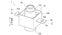
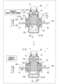
- FIG. 1 is an overall perspective view showing an initial state before operation of an electric circuit breaker device (hereinafter, also simply referred to as a "breaker device") according to an embodiment.
- FIG. 2 is a cross-sectional view taken along the line AA in FIG. 1, and is a vertical cross-sectional view showing the internal structure of the cutoff device according to the embodiment in an initial state before activation.
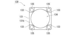
- FIG. 3 is a top view of the reinforcing frame according to the embodiment.
- FIG. 4 is a bottom view of the reinforcing frame according to the embodiment.
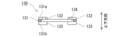
- FIG. 5 is a cross-sectional view taken along line BB of FIG.
- FIG. 6 is a top view of the conductor piece according to the embodiment.
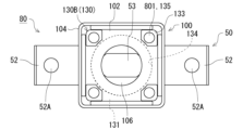
- FIG. 7 is a top view of the conductor piece assembly according to the embodiment.
- FIG. 8 is a bottom view of the conductor piece assembly according to the embodiment.
- FIG. 9 is a cross-sectional view taken along the line CC of FIG.
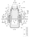
- FIG. 10 is a diagram showing an operation state of the cutoff device according to the embodiment.
- FIG. 11 is a vertical cross-sectional view showing an internal structure of a cutoff device according to the first modified example of the embodiment in an initial state before activation.
- FIG. 12 is a vertical cross-sectional view showing an internal structure of a cutoff device according to the second modification of the embodiment in an initial state before activation.
- FIG. 1 is an overall perspective view showing an initial state before operation of an electric circuit interruption device (hereinafter, also simply referred to as "interruption device") 1 according to an embodiment.
- FIG. 2 is an A-A cross-sectional view of FIG. 1, which is a vertical cross-sectional view showing an internal structure of the interruption device 1 according to an embodiment in the initial state before operation.
- a state before operation of the interruption device 1 referred to as the "initial state before operation”).
- the interruption device 1 is a device that operates when an abnormality occurs in an electric circuit included in, for example, an automobile, a home appliance, a solar power generation system, or a system including a battery (e.g., a lithium ion battery) of the electric circuit, and prevents serious damage by interrupting the electric circuit.
- a battery e.g., a lithium ion battery
- the direction along the storage space indicated by the reference numeral 13 i.e., the extension direction of the storage space 13, which is an example of the "predetermined direction” according to the present disclosure
- the igniter side indicated by the reference numeral 20 is referred to as the "upper side” in the vertical direction
- the bottom container side indicated by the reference numeral 120 is referred to as the "lower side” in the vertical direction
- a cross section along the vertical direction is referred to as a vertical cross section of the circuit breaker 1
- a cross section perpendicular to the vertical direction is referred to as a horizontal cross section of the circuit breaker 1.
- FIG. 2 viewing along the vertical direction is referred to as a "plan view".
- a conductor piece indicated by reference numeral 50 crosses the accommodation space 13 so as to be perpendicular to the vertical direction.
- the extension direction of the conductor piece 50 is referred to as the "width direction" of the circuit breaker 1.
- FIG. 2 a cross section parallel to the vertical direction and the width direction is illustrated.
- the vertical direction and the width direction of the circuit breaker 1 merely indicate the relative positional relationship of each element in the circuit breaker 1 for the convenience of explaining the embodiment.
- the circuit breaker 1 includes a housing 10 as an outer shell member, an igniter 20, a projectile 40, a conductor piece 50, a coolant material 60, and a fastening member 70.
- the housing 10 has an accommodation space 13 that extends from a first end 11 at the upper end side to a second end 12 at the lower end side.
- the accommodation space 13 accommodates a projectile 40.
- the accommodation space 13 is formed in a straight line (cylindrical in this example) so that the projectile 40 can move, and extends along the vertical direction of the circuit breaker 1.
- the circuit breaker 1 launches the projectile 40 downward by the energy of the igniter 20, and cuts off a part of the conductor piece 50 with the projectile 40, thereby interrupting the electric circuit.
- the position of the projectile 40 before the operation of the circuit breaker 1 shown in FIG. 2 is referred to as the "initial position”. Also, the direction in which the projectile 40 is launched (downward in this example) is referred to as the "launch direction”. Below, each component of the circuit breaker 1 will be described.
- the housing 10 is an outer shell member that houses various parts and elements that constitute the cutoff device 1.
- the housing 10 includes a housing main body 100 (an example of a "holding member” according to the present disclosure), a top holder 110 (an example of a “housing member” according to the present disclosure) provided on the upper side of the housing main body 100, a bottom container 120 (an example of a “housing member” according to the present disclosure) provided on the lower side of the housing main body 100, and a reinforcing frame 130 (an example of a "reinforcing member” according to the present disclosure) formed integrally with the housing main body 100.
- the top holder 110 and the bottom container 120 are joined to the housing main body 100 by a fastening member 70, thereby forming an integral housing 10.
- the reinforcing frame 130 is embedded in the housing main body 100.
- the housing body 100 is a member that holds the conductor piece 50.
- the housing body 100 is formed of an insulating resin material in order to ensure the electrical insulation of the circuit breaker 1.
- resin material for forming the housing body 100 for example, synthetic resins such as nylon, which is a type of polyamide synthetic resin, polycarbonate, polyamide, and ABS resin can be used.
- the housing body 100 may also be formed of a fiber-reinforced resin in which glass fiber is added to nylon, for example.
- the resin material for the housing body 100 is not particularly limited.
- the housing body 100 has an outer shape of a roughly rectangular column extending in the vertical direction. Therefore, the axial direction of the housing body 100 coincides with the vertical direction of the interrupter 1.
- the shape of the housing body 100 is not particularly limited.
- a hollow portion 106 (an example of a "hollow portion” according to this disclosure) is formed so as to penetrate the housing body 100 along the vertical direction.
- This hollow portion 106 is a hole that penetrates the housing body 100 in the vertical direction, and forms a part of the storage space 13.
- the cross-sectional shape of the hollow portion 106 perpendicular to the vertical direction (firing direction) is circular (see FIG. 8).
- the cross-sectional shape of the hollow portion according to this disclosure is not particularly limited.
- the hollow portion may have a rectangular cross-section, for example.
- the housing body 100 has an upper surface 101 to which the top holder 110 is fixed, and a lower surface 102 to which the bottom container 120 is fixed.
- a cylindrical upper tube wall 103 is erected on the outer periphery of the upper surface 101 of the housing body 100, extending upward from the upper surface 101.
- a cylindrical lower tube wall 104 is erected on the outer periphery of the lower surface 102 of the housing body 100, extending downward from the lower surface 102.
- the upper tube wall 103 and the lower tube wall 104 have, for example, a rectangular tube shape, but may have other shapes.
- a pair of conductor piece retaining holes 105A, 105B are formed in the housing body 100.
- the pair of conductor piece retaining holes 105A, 105B extend in a cross-sectional direction (i.e., width direction) perpendicular to the up-down direction (axial direction) of the housing body 100. More specifically, the pair of conductor piece retaining holes 105A, 105B extend in a straight line along the width direction, sandwiching a hollow portion 106 (accommodation space 13) of the housing body 100 therebetween.
- the housing body 100 is divided into upper and lower sections by a pair of conductor piece retaining holes 105A, 105B that cross the width direction of the housing body 100.
- the portion of the housing body 100 above the pair of conductor piece retaining holes 105A, 105B is referred to as the upper retaining portion 100A
- the portion below the pair of conductor piece retaining holes 105A, 105B is referred to as the lower retaining portion 100B
- the combination of these is referred to as the pair of retaining portions 100A, 100B.
- the pair of retaining portions 100A, 100B is an example of a "pair of retaining portions" according to the present disclosure.
- the top holder 110 is a member that is attached to the upper surface 101 of the housing body 100 to cooperate with the housing body 100 to form the accommodation space 13.
- the top holder 110 has a stepped, generally cylindrical shape and extends in the vertical direction.
- the inside of the top holder 110 is hollow.
- the top holder 110 includes a small diameter cylinder portion 112 located on the upper side, a large diameter cylinder portion 113 located on the lower side, a connection portion 114 that connects them, and a flange portion 111 that extends from the lower end of the large diameter cylinder portion 113 toward the outside.
- the small diameter cylinder portion 112 and the large diameter cylinder portion 113 are arranged coaxially, and the large diameter cylinder portion 113 has a larger diameter (larger diameter) than the small diameter cylinder portion 112.
- the upper end of the small diameter cylinder portion 112 constitutes the first end portion 11 of the housing 10, and an opening portion 112A to which the igniter 20 is attached is formed at the upper end.
- the flange portion 111 of the top holder 110 has a generally rectangular outline that fits inside the upper cylindrical wall 103 of the housing body 100.
- the flange portion 111 has a through hole through which the shaft portion of the bolt 701 described below can be inserted.
- the flange portion 111 is fastened to the upper surface 101 of the housing body 100 by the fastening member 70 while being disposed inside the upper cylindrical wall 103.
- the top holder 110 may be joined to the housing body 100 with a sealant applied between the upper surface 101 of the housing body 100 and the lower surface of the flange portion 111. This can increase the airtightness of the storage space 13 formed in the housing 10.
- an O-ring or a metal gasket may be interposed between the upper surface 101 of the housing body 100 and the flange portion 111 of the top holder 110 to increase the airtightness of the storage space 13.
- the hollow portion formed inside the top holder 110 communicates with the hollow portion 106 of the housing body 100 located below, forming part of the storage space 13.
- the top holder 110 configured as described above can be formed from an appropriate metal member such as stainless steel or aluminum that has excellent strength and durability.
- the material from which the top holder 110 is formed is not particularly limited.
- the above-mentioned form of the shape of the top holder 110 is also one example, and other shapes may be adopted.
- the bottom container 120 is a member that is attached to the lower surface 102 of the housing main body 100 to cooperate with the housing main body 100 to form the storage space 13.
- the bottom container 120 has a generally cylindrical shape with a bottom and extends in the vertical direction.
- the inside of the bottom container 120 is hollow.
- the bottom container 120 includes a cylindrical side wall portion 122 that extends in the vertical direction, a bottom wall portion 123 that closes the lower end of the side wall portion 122, and a flange portion 121 that extends outward from the upper end of the side wall portion 122.
- the bottom wall portion 123 constitutes the second end portion 12 of the housing 10.
- the flange portion 121 of the bottom container 120 has an outline of a rectangle that fits inside the lower tube wall 104 of the housing body 100.
- the flange portion 121 has a through hole through which the shaft portion of the bolt 701 described later can be inserted.
- the flange portion 121 is fastened to the lower surface 102 of the housing body 100 by the fastening member 70 while being disposed inside the lower tube wall 104.
- the bottom container 120 may be joined to the housing body 100 with a sealant applied between the lower surface 102 of the housing body 100 and the upper surface of the flange portion 121. This can increase the airtightness of the storage space 13 formed in the housing 10.
- an O-ring or a metal gasket may be interposed between the lower surface 102 of the housing body 100 and the flange portion 121 of the bottom container 120 to increase the airtightness of the storage space 13.
- the hollow portion formed inside the bottom container 120 communicates with the hollow portion 106 of the housing body 100 located above, and forms a part of the storage space 13.
- the bottom container 120 configured as described above can be formed of an appropriate metal member such as stainless steel or aluminum that has excellent strength and durability.
- the material for forming the bottom container 120 is not particularly limited.
- the bottom container 120 may also have a multi-layer structure.
- the exterior part of the bottom container 120 facing the outside may be formed of an appropriate metal member such as stainless steel or aluminum that has excellent strength and durability
- the interior part facing the storage space 13 may be formed of an insulating material such as synthetic resin.
- the entire bottom container 120 may be formed of an insulating material.
- the above-mentioned aspect regarding the shape of the bottom container 120 is one example, and other shapes may be adopted.
- the housing 10 in this embodiment is configured to include a housing body 100, a top holder 110, and a bottom container 120 that are assembled together, and inside thereof, an accommodation space 13 is formed that extends vertically from the first end 11 to the second end 12.
- This accommodation space 13 accommodates the igniter 20, the projectile 40, the cut portion 53 of the conductor piece 50, the coolant material 60, etc., which will be described in detail below.
- the reinforcing frame 130 is a metal frame body that is integrally joined with the housing main body 100 to reinforce the strength of the housing main body 100. As shown in Fig. 2, in this embodiment, the reinforcing frame 130 is embedded in the housing main body 100. More specifically, one reinforcing frame 130 is provided in each of a pair of holding parts 100A, 100B that are divided into upper and lower parts by a pair of conductor piece holding holes 105A, 105B.
- the reinforcing frame 130 provided in the upper holding part 100A will be referred to as an upper reinforcing frame 130A
- the reinforcing frame 130 provided in the lower holding part 100B will be referred to as a lower reinforcing frame 130B.
- the reinforcing frame 130 When the description is given without distinguishing between them, they will be simply referred to as the reinforcing frame 130.
- the reinforcing frame 130 according to this embodiment is made of aluminum.
- the reinforcing frame 130 may be made of a metal material other than aluminum, such as stainless steel. From the viewpoint of improving the strength of the housing 10, it is preferable that the reinforcing frame 130 be made of metal.
- the material of the reinforcing member according to this disclosure is not particularly limited, and in addition to metal materials, resin materials and the like can be used.
- a fiber-reinforced resin such as carbon fiber-reinforced resin may be used as the resin material forming the reinforcing member.
- FIG. 3 is a top view of the reinforcing frame 130 according to the embodiment
- FIG. 4 is a bottom view of the reinforcing frame 130 according to the embodiment
- FIG. 5 is a cross-sectional view taken along the line B-B of FIG. 3.
- the reinforcing frame 130 is formed as a ring-shaped frame body that is continuous in the circumferential direction.
- the term "ring” is not particularly limited as long as it is a closed shape that is continuous around the entire circumference so that an opening is formed, and includes a circular ring having a circular shape such as a perfect circle or an ellipse, and a polygonal ring having a polygonal shape such as a square or a triangle.
- the shape of the reinforcing member according to the present disclosure is not limited to a ring.
- the reinforcing member is not limited to a shape that is continuous around the entire circumference, and may have a discontinuous portion in some parts, or may have an intermittent shape or a discontinuous shape.
- the reinforcing frame 130 has a plate-like main body 131 that is roughly rectangular in plan view and perpendicular to the vertical direction, a plurality of upper surface convex portions 132 provided on the upper surface 131a of the main body 131, and a plurality of lower surface convex portions 133 provided on the lower surface 131b of the main body 131.
- the main body 131 has a through hole 134 that penetrates the main body 131 in the vertical direction. More specifically, the through hole 134 penetrates the main body 131 from the upper surface 131a to the lower surface 131b at the center position of the main body 131.
- the reinforcing frame 130 is formed in a ring shape with the through hole 134 as an opening.
- the through hole 134 in this embodiment has a circular shape in a cross section perpendicular to the vertical direction (firing direction).
- the shape of the through hole 134 is not particularly limited.
- the upper surface convex portion 132 is a portion that protrudes upward from the upper surface 131a, and one is provided at each of the four corners of the main body portion 131.
- the lower surface convex portion 133 is a portion that protrudes downward from the lower surface 131b, and one is provided at each of the four corners of the main body portion 131.
- the upper surface convex portion 132 and the lower surface convex portion 133 are examples of the "exposed portion" according to the present disclosure.
- the shape of the exposed portion according to the present disclosure is not particularly limited, and does not have to be convex.
- the main body portion 131 is formed with a mounting hole 135 that penetrates from the top surface of the upper surface convex portion 132 to the top surface of the lower surface convex portion 133.
- the mounting hole 135 is provided at each of the four corners of the main body portion 131.
- the mounting hole 135 is formed as a through hole into which the shaft portion of the bolt 701 described later can be inserted.
- the mounting holes according to the present disclosure are not limited to through holes, and various configurations can be selected according to the type of fastening member, for example, screw holes.
- the mounting holes may also be blind holes.
- the above configurations regarding the shape of the reinforcing frame 130 are only examples, and other shapes may also be used.
- the igniter 20 is an electric igniter that includes an ignition portion 21 containing an ignition charge and an igniter body 22 having a pair of conductive pins (not shown) connected to the ignition portion 21, and that releases combustion gas into the accommodation space 13 upon activation.
- the igniter 20 is attached to the housing 10 with a portion of it accommodated in the accommodation space 13 (more specifically, in a hollow portion formed inside the small diameter cylinder portion 112).
- the igniter body 22 has a generally cylindrical body 221 that extends vertically and is housed inside the small-diameter cylinder 112 of the top holder 110, and a connector 222 located on the top of the body 221, and is surrounded by, for example, insulating resin.
- the igniter body 22 is fixed to the small-diameter cylinder 112, for example, by pressing the body 221 into the inner circumferential surface of the small-diameter cylinder 112.
- a constricted portion whose outer circumferential surface is recessed compared to other portions, is formed in an annular shape along the circumferential direction of the body 221 at the axial middle portion of the body 221, and an O-ring 223 is fitted into this constricted portion.
- the O-ring 223 is made of, for example, rubber (e.g., silicone rubber) or synthetic resin, and functions to increase the airtightness between the inner circumferential surface of the small-diameter cylinder 112 and the body 221.
- the connector portion 222 has a cylindrical shape extending in the vertical direction, and is disposed so as to protrude outside the housing 10 through an opening 112A formed at the upper end of the small diameter cylinder portion 112.
- a pair of conductive pins connected to the ignition portion 21 are disposed inside the connector portion 222.
- the connector portion 222 is configured so that a power supply connector (not shown) can be connected, and the pair of conductive pins are connected to the power supply by connecting the connector portion 222 of the igniter 20 to the power supply connector. This makes it possible to supply an operating current to the igniter 20.
- the ignition section 21 of the igniter 20 is arranged to face the accommodation space 13 of the housing 10 (more specifically, the hollow portion formed inside the large diameter cylinder section 113).
- the ignition section 21 is configured, for example, in a form in which an ignition charge is accommodated in an igniter cup.
- the ignition charge is accommodated in the igniter cup of the ignition section 21 in a state in which it is in contact with a bridge wire (resistance element) that is connected so as to connect the base ends of a pair of conductive pins.
- the ignition charge for example, ZPP (zirconium potassium perchlorate), ZWPP (zirconium tungsten potassium perchlorate), THPP (titanium hydride potassium perchlorate), lead tricinate, etc. may be used.
- the lower surface of the igniter cup in the ignition section 21, that is, the surface on the firing direction side, is formed as a cleavage surface 21A that cleaves when the igniter 20 is activated.
- an operating current for igniting the ignition charge is supplied from the power source to the conductive pin, causing the bridge wire in the ignition section 21 to heat up, resulting in the ignition charge in the igniter cup igniting and burning, generating combustion gas.
- the ignition charge burns in the igniter cup of the igniter section 21, the pressure in the igniter cup rises, the cleavage surface 21A of the igniter cup cleaves, and the combustion gas is released from the igniter cup into the storage space 13. More specifically, the combustion gas from the igniter cup is released toward the recessed portion 411 in the piston portion 41 (described later) of the projectile 40 placed in the storage space 13.
- the projectile 40 is a member that is disposed in the accommodation space 13, and receives energy from the igniter 20 when the igniter 20 is activated, and is launched in the launch direction (downward in this example) along the accommodation space 13, thereby cutting off a portion of the conductor piece 50.
- the projectile 40 is formed of an insulating material such as a synthetic resin, and includes a piston portion 41 and a rod portion 42 connected to the piston portion 41.
- the piston portion 41 has a generally cylindrical shape extending in the vertical direction, and has an outer diameter that generally corresponds to the inner diameter of the large diameter cylinder portion 113 in the top holder 110.
- the diameter of the piston portion 41 may be slightly smaller than the inner diameter of the large diameter cylinder portion 113.
- a cylindrical recessed portion 411 is formed on the upper surface of the piston portion 41, that is, the surface opposite to the firing direction, and the ignition portion 21 is received in this recessed portion 411.
- the bottom surface of the recessed portion 411 is formed as a pressure receiving surface 411A that receives energy from the igniter 20 when the igniter 20 is activated.
- a constricted portion whose outer circumferential surface is recessed compared to other places is formed in an annular shape along the circumferential direction of the piston portion 41 in the axial middle portion of the piston portion 41, and an O-ring 43 is fitted into this constricted portion.
- the O-ring 43 is made of, for example, rubber (e.g., silicone rubber) or synthetic resin, and functions to increase the airtightness between the inner circumferential surface of the large-diameter cylinder portion 113 and the piston portion 41.
- the rod portion 42 of the projectile 40 is, for example, a rod-shaped member that has an outer circumferential surface with a smaller diameter than the piston portion 41 and extends in the vertical direction, and is integrally connected to the lower end side of the piston portion 41.
- the lower end surface of the rod portion 42 i.e., the end surface on the launching direction side
- the rod portion 42 has a roughly cylindrical shape, but the shape is not particularly limited and can be changed according to the shape and size of the cut portion 53 to be cut from the conductor piece 50 when the interrupter 1 is activated.
- the rod portion 42 may have a columnar shape such as a cylindrical shape or a rectangular column.
- the tip side area including the cutting surface 421 in the rod portion 42 of the projectile 40 is positioned in the hollow portion of the housing main body 100 (forming a part of the storage space 13).
- the diameter of the rod portion 42 is, for example, slightly smaller than the inner diameter of the inner peripheral surface of the housing body 100, and is configured so that the outer peripheral surface of the rod portion 42 is guided along the inner peripheral surface when the projectile 40 is launched.
- the projectile 40 configured as described above will be described in detail later, but when the igniter 20 is activated, the upper surface of the piston portion 41, including the pressure-receiving surface 411A, receives energy from the igniter 20, causing the projectile 40 to be launched from the initial position shown in FIG. 2 and move at high speed in the launch direction (downward) along the accommodation space 13.
- the piston portion 41 of the projectile 40 is accommodated inside the large diameter cylinder portion 113 in the top holder 110, and can slide in the axial direction along the inner wall surface of the large diameter cylinder portion 113.
- the shape of the projectile 40 is not limited to the above-mentioned shape, and can be changed as appropriate depending on the shape of the housing 10, etc.
- FIG. 6 is a top view of the conductor piece 50 according to the embodiment.
- the conductor piece 50 is a conductive metal body that constitutes a part of the components of the circuit breaker 1 and forms a part of a specific electric circuit when the circuit breaker 1 is attached to the circuit breaker.
- the conductor piece 50 may be called a bus bar.
- the conductor piece 50 may be formed of a metal such as copper (Cu).
- the conductor piece 50 may be formed of a metal other than copper, or may be formed of an alloy of copper and another metal. Examples of metals other than copper contained in the conductor piece 50 include manganese (Mn), nickel (Ni), platinum (Pt), aluminum (Al), brass, gold (Au), silver (Ag), and duralumin.
- the conductor piece 50 is formed as a long and thin flat piece as a whole.
- the conductor piece 50 includes a first connection end 51, which is one end in the extension direction of the conductor piece 50, and a second connection end 52, which is the other end.
- the conductor piece 50 also has a cut-out portion 53 in a part thereof.
- the cut-out portion 53 is located between the first connection end 51 and the second connection end 52 (in this example, the middle part).
- the first connection end 51 and the second connection end 52 are provided with connection holes 51A and 52A, respectively. These connection holes 51A and 52A are used to connect to other conductors (e.g., lead wires) in the electric circuit.
- the cut-out portion 53 is a portion that is forcibly and physically cut by the rod portion 42 of the projectile 40 and cut off from the first connection end 51 and the second connection end 52 when an abnormality such as an excessive current occurs in the electric circuit to which the interrupter 1 is applied.
- the cut-out portion 53 is formed so as to interrupt the electrical circuit by being cut off by the projectile 40 fired by the activation of the igniter 20. More specifically, the cut-out portion 53 is formed as a portion that, when cut off from the conductor piece 50, causes the conductor piece 50 to be severed. At both ends of the cut-out portion 53 in the conductor piece 50, cuts (slits) 54 are formed so that the cut-out portion 53 can be easily cut off.
- the conductor piece 50 may have various shapes, and the shape is not particularly limited.
- the surface of the first connection end 51, the surface of the second connection end 52, and the surface of the cut-out portion 53 form the same plane, but this is not limited to this.
- the conductor piece 50 may have the cut-out portion 53 connected perpendicularly or at an angle to the first connection end 51 and the second connection end 52.
- the planar shape of the cut-out portion 53 in the conductor piece 50 is also not particularly limited.
- the shapes of the first connection end 51 and the second connection end 52 in the conductor piece 50 are also not particularly limited.
- the notch 54 in the conductor piece 50 can be omitted as appropriate.
- the conductor piece 50 configured as described above is held in the housing body 100 in a state in which it is inserted into a pair of conductor piece holding holes 105A, 105B formed in the housing body 100.
- the first connection end 51 of the conductor piece 50 is held in a state in which it is inserted into the conductor piece holding hole 105A
- the second connection end 52 is held in a state in which it is inserted into the conductor piece holding hole 105B.
- the cut-out portion 53 of the conductor piece 50 is positioned in the hollow portion (accommodation space 13) of the housing body 100.
- the conductor piece 50 is provided in the housing 10 so as to cross the accommodation space 13 in the width direction.
- the conductor piece 50 attached to the housing body 100 is arranged so that the cut-out portion 53 is located on the path of the projectile 40 in the accommodation space 13 (i.e., below the projectile 40), and is held in a position perpendicular to the extension direction (launch direction) of the accommodation space 13.
- the first connection end 51 and the second connection end 52 of the conductor piece 50 are exposed to the outside of the housing 10, and other conductors (such as lead wires) that form an electric circuit are connected to the connection holes 51A and 52A.
- the reference character L1 in FIG. 6 indicates the outer circumferential position of the rod portion 42 located on the upper part of the conductor piece 50 when the conductor piece 50 is attached to the housing body 100 of the interrupter 1.
- the conductor piece 50 is installed so that the outer circumferential position L1 of the rod portion 42 roughly overlaps with the positions of the notches 54 located at both ends of the cutout portion 53.
- the cross-sectional area of the accommodation space 13 is larger than the cross-sectional area of the cutout portion 53, so that a gap is formed on the side of the cutout portion 53.
- the cut-out portion 53 of the conductor piece 50 held in the pair of conductor piece holding holes 105A, 105B in the housing body 100 is horizontally disposed across the storage space 13 of the housing 10.
- the region (space) of the storage space 13 in the housing 10 where the projectile 40 is disposed across the cut-out portion 53 of the conductor piece 50 is referred to as the "projectile initial placement region R1"
- the region (space) located on the opposite side of the projectile 40 i.e., the launch direction side
- the projectile initial placement region R1 and the arc-extinguishing region R2 are not completely isolated by the cut-out portion 53, but are connected to each other.
- the projectile initial placement region R1 and the arc-extinguishing region R2 may be completely isolated by the cut-out portion 53.
- the projectile initial placement region R1 contains the projectile 40
- the arc-extinguishing region R2 contains the coolant material 60 as an arc-extinguishing material.
- the arc-extinguishing region R2 is a region (space) for receiving the cut-out portion 53 that is cut off by the rod portion 42 of the projectile 40 that is launched when the cut-out device 1 (igniter 20) is activated.
- the coolant material 60 is a cooling material for suppressing the generation of an arc when a current is interrupted or for extinguishing (extinguishing) the generated arc by removing and cooling the arc and the thermal energy of the excised portion 53 generated when the projectile 40 excises the excised portion 53 of the conductor piece 50. As shown in FIG. 2, the coolant material 60 is disposed in the arc extinguishing region R2 in the accommodation space 13.
- the arc-extinguishing region R2 in the circuit breaker 1 is a space for receiving the cut-off portion 53 cut off from the first connection end 51 and the second connection end 52 of the conductor piece 50 by the projectile 40, and at the same time serves as a space for effectively extinguishing the arc generated when the projectile 40 cuts off the cut-off portion 53.
- a coolant material 60 is disposed in the arc-extinguishing region R2 as an arc-extinguishing material.
- the coolant material 60 is solid. In another aspect of the embodiment, the coolant material 60 is formed of a shape-retaining body.
- the shape-retaining body is, for example, a material that maintains a certain shape when no external force is applied, and that can maintain its integrity (does not fall apart) even if deformation occurs when an external force is applied.
- a fibrous body molded into a desired shape can be an example of a shape-retaining body.
- the coolant material 60 is formed of metal fibers, which are shape-retaining bodies.
- examples of metal fibers that form the coolant material 60 include at least one of steel wool and copper wool.
- the coolant material 60 may include inorganic oxides such as zeolite, silica, and alumina.
- the above aspects of the coolant material 60 are merely examples, and the coolant material 60 is not limited to these.
- the coolant material 60 is, for example, formed in a bowl shape and arranged so as to fit along the inner wall and bottom of the bottom container 120 (the arc-extinguishing region R2 of the storage space 13).
- the coolant material 60 may also be formed in a disk shape and arranged so as to fit along the bottom of the bottom container 120.
- the coolant material 60 may also be a modified resin material that functions as an arc-extinguishing material.
- the modified resin material is modified by the arc generated when the projectile 40 cuts the cut-out portion 53 of the conductor piece 50 and the heat of the cut-out portion 53, and this modification consumes thermal energy, thereby contributing to the extinguishing (elimination) of the arc.
- the modification of the modified resin material is mainly caused by the heat of the arc, but it is also affected by other heat such as the heat generated when the cut-out portion 53 is cut and the heat of combustion of the ignition charge, and the heat received from the ignition of the ignition charge to the completion of extinguishing the arc is referred to as the heat associated with the activation of the igniter 20.
- the modified resin material is a synthetic resin containing silicone.
- the modified resin material is not limited to silicone, and may be made of other resins such as polyurethane, polyethylene, polypropylene, polyamide, and nitrile rubber.
- the modified resin material may be at least partially modified by heat, and may be made of a composite material containing glass or ceramic fillers.
- the modified resin material is made of a material that is more easily modified by heat, such as decomposed or volatilized, than other resin materials such as the housing 10 and the projectile 40, and this modification can effectively consume the heat of the arc.
- the modified resin material of this embodiment has components such as silica that are generated by thermal decomposition and exhibit high resistance, and the scattering of these components contributes to improving insulation after cutting.
- the modified resin material is not limited to a solid member formed into a predetermined shape, but may be a gel-like material or a highly viscous liquid material applied to the wall surface within the storage space 13.
- the modified resin material may also be a synthetic resin melted in an organic solvent such as toluene that is applied to the wall surface within the storage space 13 and then fixed to the wall surface by volatilizing the organic solvent.
- the housing body 100, the reinforcing frame 130, and the conductor piece 50 are integrally molded by injection molding (more specifically, insert molding).
- injection molding more specifically, insert molding
- an assembly formed by the housing body 100, the reinforcing frame 130, and the conductor piece 50 as shown in Fig. 2 will be referred to as a conductor piece assembly 80.
- FIG. 7 is a top view of the conductor piece assembly 80 according to the embodiment
- FIG. 8 is a bottom view of the conductor piece assembly 80 according to the embodiment
- FIG. 9 is a cross-sectional view taken along the line C-C of FIG. 7.
- the upper reinforcing frame 130A and the lower reinforcing frame 130B are embedded inside the housing body 100 so that the cavity 106 of the housing body 100 is located inside the through hole 134. Therefore, the cavity 106 is surrounded by the reinforcing frame 130.
- the reinforcing frame 130 is provided on the outer periphery of the cavity 106 so as to extend along the circumferential direction of the cavity 106.
- the reinforcing frame 130 according to the present embodiment is made of metal, and is therefore embedded inside the housing body 100 so as not to be exposed to the pair of conductor piece holding holes 105A, 105B and the cavity 106 of the housing body 100, from the viewpoint of ensuring electrical insulation performance after the operation of the interrupter 1.
- the present disclosure is not limited thereto.
- the top surface of the upper surface convex portion 132 of the upper reinforcement frame 130A which is the opening surface of the mounting hole 135 (the surface where the mounting hole 135 is open), is exposed to the outside of the housing body 100 from the upper surface 101 of the housing body 100.
- the upper reinforcement frame 130A is embedded inside the housing body 100 except for the top surface of the upper surface convex portion 132.
- the top surface of the lower surface convex portion 133 of the lower reinforcement frame 130B which is the opening end surface of the mounting hole 135, is exposed to the outside of the housing body 100 from the lower surface 102 of the housing body 100.
- the lower reinforcement frame 130B is embedded inside the housing body 100 except for the top surface of the lower surface convex portion 133. Furthermore, the upper reinforcement frame 130A and the lower reinforcement frame 130B are arranged in the housing main body 100 so that their mounting holes 135 overlap each other in a plan view (in other words, when viewed along the firing direction). That is, in a plan view, the position of the mounting hole 135 of the upper reinforcement frame 130A and the position of the mounting hole 135 of the lower reinforcement frame 130B match. As shown in Figs.
- the conductor piece assembly 80 is formed with a bolt insertion hole 801 that penetrates from the top surface of the upper surface convex portion 132 of the upper reinforcement frame 130A to the top surface of the lower surface convex portion 133 of the lower reinforcement frame 130B.
- the bolt insertion hole 801 is a through hole that penetrates the upper reinforcement frame 130A, the housing main body 100, and the lower reinforcement frame 130B in the vertical direction, and is formed as a through hole through which the shaft portion of the bolt 701 can be inserted.
- a portion of the bolt insertion hole 801 is formed by the mounting hole 135 of the upper reinforcement frame 130A and the mounting hole 135 of the lower reinforcement frame 130B.
- the reinforcing frame 130 is molded integrally with the housing body 100, but the present disclosure is not limited to this.
- the reinforcing member according to the present disclosure may be molded separately from the conductor holding member.
- the reinforcing frame 130 is embedded inside the housing body 100 except for a portion thereof, but the present disclosure is not limited to this.
- the reinforcing member according to the present disclosure may be completely embedded inside the conductor holding member, or may be joined to the conductor holding member so that a portion or all of the reinforcing member is exposed on the surface of the conductor holding member.
- the fastening member 70 is a member for attaching the top holder 110 and the bottom container 120 to the housing main body 100. As shown in FIG. 2, the fastening member 70 according to this embodiment is configured to include a bolt 701 provided on the upper side and a nut 702 provided on the lower side.
- the bolt 701 has a head 701a and a shaft portion 701b extending from the head 701a.
- the head 701a is disposed on the upper side of the flange portion 111 of the top holder 110.
- the shaft portion 701b is inserted through a through hole formed in the flange portion 111 of the top holder 110, a bolt insertion hole 801 formed in the conductor piece assembly 80, and a through hole formed in the flange portion 121 of the bottom container 120.
- the nut 702 is screwed onto the shaft portion 701b of the bolt 701 protruding downward from the flange portion 121 of the bottom container 120.
- the flange portion 111 of the top holder 110 is sandwiched between the head 701a of the bolt 701 and the housing main body 100, and the flange portion 121 of the bottom container 120 is sandwiched between the nut 702 and the housing main body 100. In this manner, the top holder 110 and the bottom container 120 are attached to the housing main body 100.
- the fastening member according to the present disclosure is not limited to a combination of a bolt and a nut.
- the mounting hole may be a screw hole (female thread)
- the fastening member may be a male thread member
- the housing member may be fastened to the conductor holding member by screwing the screw hole and the male thread member. This eliminates the need for nuts, so the number of parts can be reduced, and the manufacturing equipment can be simplified and costs can be reduced.
- the reinforcing member may be formed as a self-locking nut by processing the mounting hole with a self-locking tap.
- a self-locking screw hole means a screw hole with a structure to prevent loosening against vibration, etc.
- a self-locking nut means a nut with a self-locking screw hole.
- the flange portion 111 of the top holder 110 fastened to the upper surface 101 of the housing body 100 abuts against the top surface of the upper surface convex portion 132.
- the flange portion 121 of the bottom container 120 fastened to the lower surface 102 of the housing body 100 abuts against the top surface of the lower surface convex portion 133.
- the plastic housing body 100 is prevented from being deformed (deformed, for example, collapsed) by the fastening force of the fastening member 70.
- the bolt 701 is inserted into the bolt insertion hole 801 from above to fasten the various components, but the bolt 701 may be inserted into the bolt insertion hole 801 from below to fasten the various components.
- the flange portion 121 of the bottom container 120 may be sandwiched between the head 701a of the bolt 701 and the housing body 100, and the flange portion 111 of the top holder 110 may be sandwiched between the nut 702 and the housing body 100.
- FIG. 2 shows the initial state before operation of the circuit breaker 1.
- the projectile 40 in the circuit breaker 1 is set to an initial position in which the piston portion 41 is positioned on the first end 11 side (upper end side) in the accommodation space 13 and the cut surface 421 formed on the lower end of the rod portion 42 is positioned on the upper surface of the cut portion 53 of the conductor piece 50.
- the circuit breaker 1 further includes an abnormality detection sensor (not shown) that detects an abnormal state of a device (such as a vehicle, a power generation facility, or a storage facility) to which the electric circuit to be interrupted is connected, and a control unit (not shown) that controls the operation of the igniter 20.
- the abnormality detection sensor may be capable of detecting an abnormal state based on the voltage or the temperature of the conductor piece 50 in addition to the current flowing through the conductor piece 50.
- the abnormality detection sensor may also be, for example, an impact sensor, a temperature sensor, an acceleration sensor, or a vibration sensor, and may detect an abnormal state such as an accident or fire based on impact, temperature, acceleration, or vibration in a device such as a vehicle.
- the control unit of the circuit breaker 1 is, for example, a computer that can perform a predetermined function by executing a predetermined control program.
- the predetermined function of the control unit can also be realized by corresponding hardware.
- the abnormal current may be a current value that exceeds a predetermined threshold value set for protecting a predetermined electric circuit.
- the abnormality detection sensor and control unit described above do not need to be included as components of the interrupter 1, and may be included in a device other than the interrupter 1, for example. Also, the abnormality detection sensor and control unit are not essential components of the interrupter 1.
- the control unit of the circuit breaker 1 activates the igniter 20. That is, an operating current is supplied to the conductive pin of the igniter 20 from an external power source (not shown), causing the ignition charge in the ignition portion 21 to ignite and burn, generating combustion gas. Then, the pressure rises in the ignition portion 21, causing the cleavage surface 21A to cleave, and the ignition charge combustion gas is released from the ignition portion 21 into the accommodation space 13.
- the ignition portion 21 of the igniter 20 is received in the recess 411 in the piston portion 41, and the cleavage surface 21A of the ignition portion 21 is disposed opposite the pressure-receiving surface 411A of the recess 411 in the projectile 40. Therefore, the combustion gas from the ignition portion 21 is released into the recess 411, and the pressure of the combustion gas (combustion energy) is transmitted to the upper surface of the piston portion 41, including the pressure-receiving surface 411A. As a result, the projectile 40 is launched in the launch direction (downward) along the accommodation space 13.
- FIG. 10 is a diagram showing the operating status of the interrupter 1 according to the embodiment.
- the upper part of FIG. 10 shows the status during operation of the interrupter 1
- the lower part of FIG. 10 shows the status after operation of the interrupter 1 is completed.
- the projectile 40 which receives the pressure (combustion energy) of the combustion gas of the ignition charge due to the operation of the igniter 20
- the cut-out portion 53 of the conductor piece 50 located in the path of the projectile 40.
- the cut-out surface 421 formed on the lower end side of the rod portion 42 shears and pushes through each boundary portion between the first connection end 51 and the second connection end 52 of the conductor piece 50 and the cut-out portion 53.
- the cut-out portion 53 is cut off from the conductor piece 50.
- the shape and dimensions of the projectile 40 can be freely determined as long as the projectile 40 can move smoothly along the extension direction (axial direction) of the storage space 13 when the igniter 20 is activated.
- the outer diameter of the piston portion 41 in the projectile 40 may be set to a dimension equal to the inner diameter of the large diameter cylinder portion 113 in the top holder 110.
- the projectile 40 moves downward along the extension direction (axial direction) of the accommodation space 13 by a predetermined stroke until the lower end surface of the piston portion 41 abuts (collides) with the upper surface 101 of the housing body 100. Then, in this state, the cut-out portion 53 cut off from the conductor piece 50 by the rod portion 42 of the projectile 40 is received in the arc-extinguishing region R2 in which the coolant material 60 is disposed. By cutting off the cut-out portion 53 from the conductor piece 50, the first connection end 51 and the second connection end 52 located at both ends of the conductor piece 50 become electrically disconnected, and the predetermined electric circuit to which the interrupter 1 is applied is forcibly interrupted.
- the circuit breaker 1 has a coolant material 60 disposed in the arc-extinguishing region R2. Therefore, the cut-out portion 53 received in the arc-extinguishing region R2 is rapidly cooled by the coolant material 60. As a result, when the projectile 40 cuts out the cut-out portion 53 from the conductor piece 50 that constitutes part of a specified electric circuit, even if an arc occurs on the cut surface of the cut-out portion 53 of the conductor piece 50, the generated arc is quickly and effectively extinguished.
- the interrupter 1 includes the housing 10 that defines the accommodation space 13 therein extending in a predetermined direction (up and down in this example), the igniter 20 provided in the housing 10, the projectile 40 that is disposed in the accommodation space 13 and is fired along the accommodation space 13 by receiving energy from the igniter 20 when the igniter 20 is activated, and the conductor piece 50 that is provided in the housing 10 so as to cross the accommodation space 13 and forms part of an electric circuit.
- the conductor piece 50 has a cut-out portion 53 formed in a part thereof so as to be cut off by the projectile 40 fired by activation of the igniter 20 to interrupt the electric circuit, and the cut-out portion 53 is disposed so as to be located on the path of the projectile 40 in the accommodation space 13.
- the housing 10 of the interrupter 1 has a resin housing main body 100 that extends in the vertical direction and is penetrated by a hollow portion 106 that forms part of the accommodation space 13, and a reinforcing frame 130 that reinforces the housing main body 100, and the housing main body 100 holds the conductor piece 50 such that the cut portion 53 of the conductor piece 50 is located inside the hollow portion 106.
- the reinforcing frame 130 is coupled to the housing main body 100 so as to surround the periphery of the hollow portion 106.
- the resin housing that holds the conductor is deformed or damaged by the impact generated when the projectile cuts the conductor, this could affect the electrical insulation performance after the circuit breaker is activated.
- the resin of the housing may crack when the conductor is cut, and the copper evaporated from the conductor may enter the cracks in the resin, lowering the insulation resistance.
- the reinforcing frame 130 is joined to the housing body 100 so as to surround the periphery of the cavity 106. Since the reinforcing frame 130 is disposed around the cavity 106, the housing body 100, which is a member defining the cavity 106, is suitably reinforced. This increases the strength of the housing 10. As a result, deformation or damage to the housing body 100 caused by the impact when the conductor piece 50 is cut is suppressed, and thus the deterioration of the electrical insulation performance of the interrupter 1 after operation can be suppressed.
- the reinforcing frame 130 is formed in a continuous ring shape so as to surround the periphery of the cavity 106, so that the strength of the housing 10 can be more suitably increased.
- the impact load acting on the housing body 100 when the conductor piece 50 is cut is high in the vicinity of the conductor piece 50 (i.e., near the pair of conductor piece holding holes 105A, 105B). Therefore, it is preferable that the reinforcing frame 130 is disposed in the vicinity of the conductor piece 50.
- the reinforcing frame 130 is disposed at least in an area that overlaps with the conductor piece 50 in a plan view (i.e., when viewed along the direction of emission). This effectively prevents deformation or damage to the housing body 100 in the vicinity of the conductor piece 50.
- the interrupter 1 of this embodiment by reinforcing the housing body 100, even materials with relatively low impact resistance can be used as the material for the housing body 100.
- materials with relatively low impact resistance can be used as the material for the housing body 100.
- nylon which has a heat resistance of 200°C or higher, can be used as the material for the housing body 100 instead of polycarbonate, which is thermally deformed at temperatures of 175°C or lower.
- the reinforcing frame 130 according to this embodiment is made of metal. Therefore, the plastic housing body 100 can be more effectively reinforced.
- the reinforcing frame 130 by making the reinforcing frame 130 out of aluminum, it is possible to increase the strength of the housing 10 while suppressing an increase in the weight of the housing 10.
- the reinforcing member of the present disclosure may be formed from an iron-based material such as stainless steel or carbon steel. By using an iron-based material, it is possible to suppress the cost of the reinforcing member.
- An example of the carbon steel that is the material for the reinforcing member is S25C.
- the reinforcing frame 130 is integrally molded with the housing body 100 by injection molding. This allows the housing body 100 and the reinforcing frame 130 to be firmly bonded together, thereby providing suitable reinforcement for the housing body 100.
- the housing 10 has a top holder 110 and a bottom container 120 that are attached to the housing body 100 to cooperate with the housing body 100 to form the storage space 13.
- the reinforcing frame 130 has an upper surface convex portion 132 and a lower surface convex portion 133 exposed to the outside of the housing body 100, and the upper surface convex portion 132 and the lower surface convex portion 133 have mounting holes 135 for mounting the top holder 110 and the bottom container 120 to the housing body 100 using a fastening member 70.
- the top holder 110 and the bottom container 120 are fastened to the housing body 100 in a state of abutting against the reinforcing frame 130, so that the plastic housing body 100 can be prevented from being deformed (such as collapsing) due to the fastening force of the fastening member 70.
- the top holder 110 and the bottom container 120 correspond to an example of a "housing member" according to the present disclosure, but the housing member according to the present disclosure is not limited to these.
- the housing member may be, for example, only one of the top holder 110 and the bottom container 120, or may include other members.
- the housing main body 100 has a pair of holding parts 100A, 100B formed to sandwich the conductor piece 50 from a predetermined direction (the vertical direction in this example), and one reinforcing frame 130 is provided on each of the pair of holding parts 100A, 100B.
- a predetermined direction the vertical direction in this example
- one reinforcing frame 130 is provided on each of the pair of holding parts 100A, 100B.
- an upper reinforcing frame 130A is provided on the upper holding part 100A
- a lower reinforcing frame 130B is provided on the lower holding part 100B.
- the number of reinforcing members is not particularly limited. Only one reinforcing member may be provided, or three or more reinforcing members may be provided. For example, only one of the upper reinforcing frame 130A and the lower reinforcing frame 130B may be provided.
- [Modification 1] 11 is a vertical cross-sectional view showing an internal structure of the shutoff device 1A according to the first modification of the embodiment in an initial state before operation.
- the shutoff device 1A according to the first modification is different from the shutoff device 1 described above in that the upper reinforcement frame 130A and the lower reinforcement frame 130B are not integrally molded with the housing main body 100, and the housing main body 100 is sandwiched between the upper reinforcement frame 130A and the lower reinforcement frame 130B from above and below.
- the upper reinforcement frame 130A is sandwiched between the upper surface 101 of the housing main body 100 and the flange portion 111 of the top holder 110, and the lower reinforcement frame 130B is sandwiched between the lower surface 102 of the housing main body 100 and the flange portion 121 of the bottom container 120, and each member is fastened by the fastening member 70. That is, in the first modification, the upper reinforcement frame 130A and the lower reinforcement frame 130B, which are separate from the housing main body 100, are fastened to the housing main body 100 by the fastening member 70.
- the housing body 100 is sandwiched from above and below by a pair of reinforcing frames 130, so that the housing body 100 can be suitably reinforced. Furthermore, in the interrupter 1A according to the first modification, an upper reinforcing frame 130A is interposed between the upper surface 101 of the housing body 100 and the flange portion 111 of the top holder 110, and a lower reinforcing frame 130B is interposed between the lower surface 102 of the housing body 100 and the flange portion 121 of the bottom container 120, so that the pair of reinforcing frames 130 function as a gasket. This can increase the airtightness of the storage space 13. Note that, like the interrupter 1A according to the first modification, the reinforcing member according to the present disclosure does not have to be integrally molded with the conductor piece holding member.
- [Modification 2] 12 is a vertical cross-sectional view showing an internal structure of the cutoff device 1B according to the second modification of the embodiment in an initial state before operation.
- the cutoff device 1B according to the second modification differs from the cutoff device 1 described above in that the bottom container 120 of the housing 10 and the nut 702 of the fastening member 70 are integrally molded with a resin material.
- the bottom container 120 and the nut 702 are integrally molded with a resin material in a state in which the bottom container 120 is not attached to the housing main body 100 and the bolt 701 is not screwed into the nut 702.
- the outer surfaces of the bottom container 120 and the nut 702 are coated with a resin material in a state in which the nut 702 is disposed on the outer surface of the flange portion 121 of the bottom container 120.
- Reference numeral 90 in FIG. 12 indicates a resin coating that integrates the bottom container 120 of the housing 10 and the nut 702 of the fastening member 70.
- the bolt 701 is fixed to the bottom container 120 by the resin coating 90.
- the bolt 701 is simply screwed into the nut 702 in the fixed state, which facilitates the assembly work of the housing 10.
- the nut 702 is less likely to loosen when the housing 10 is assembled.
- the resin coating 90 covers the entire outer surface of the bottom container 120. This provides the bottom container 120 with electrical insulation performance.
- the material of the resin coating 90 is not particularly limited, and synthetic resins such as nylon, polycarbonate, polyamide, and ABS resin can be used.
- the top holder 110 of the housing 10 and the nut 702 may be integrally molded from a resin material. That is, in the second modification, it is sufficient that the nut for attaching the housing member to the conductor holding member using the bolt is integrally molded from a resin material.
- interrupter device 10 housing 13: storage space 20: igniter 40: projectile 50: conductor piece 53: cut-out portion 60: coolant material 70: fastening member 100: housing body (an example of a conductor piece holding member) 110: Top holder (an example of a housing member) 120: Bottom container (an example of a housing member) 130: Reinforcing frame (an example of a reinforcing member)
Landscapes
- Fuses (AREA)
- Air Bags (AREA)
Abstract
Description
上記課題を解決するために、本開示の一態様に係る電気回路遮断装置は、以下の構成を採用した。即ち、本開示に係る電気回路遮断装置は、所定の方向に延在する収容空間を内部に形成するハウジングと、前記ハウジングに設けられた点火器と、前記収容空間に配置された発射体であって、前記点火器の作動時に前記点火器からエネルギーを受けることで前記収容空間に沿って発射される発射体と、前記収容空間を横切るように前記ハウジングに設けられると共に電気回路の一部を形成する導体片であって、その一部に前記点火器の作動により発射された前記発射体によって切除されることで前記電気回路を遮断するように形成された被切除部を有し、前記被切除部が前記収容空間における前記発射体の進路上に位置するように配置された導体片と、を備え、前記ハウジングは、前記所定の方向に延在すると共に前記収容空間の一部を形成する空洞部が貫通した樹脂製の導体保持部材であって、前記被切除部が前記空洞部の内部に位置するように前記導体片を保持する導体保持部材と、前記導体保持部材を補強する補強部材と、を有し、前記補強部材は、前記空洞部の周囲を取り囲むように前記導体保持部材と結合されている。
上記の態様1において、前記補強部材は、金属製であってもよい。
上記の態様1又は2において、前記補強部材は、アルミニウム製であってもよい。
上記の態様1又は2において、前記補強部材は、鉄系材料により形成されていてもよい。
上記の態様1から4の何れかにおいて、前記補強部材は、前記導体保持部材と一体成形されていてもよい。
上記の態様1から4の何れかにおいて、前記導体保持部材とは別体の前記補強部材が、締結部材によって前記導体保持部材に締結されていてもよい。
上記の態様1から6の何れかにおいて、前記ハウジングは、前記導体保持部材に取り付けられることで前記導体保持部材と協働して前記収容空間を形成するハウジング部材を有し、前記補強部材は、前記導体保持部材の外部に露出した露出部を有し、前記露出部には、締結部材を用いて前記ハウジング部材を前記導体保持部材に取り付けるための取付穴が形成されていてもよい。
上記の態様7において、前記取付穴は、ねじ穴として形成され、前記締結部材は、おねじ部材として形成され、前記ねじ穴と前記おねじ部材との螺合によりハウジング部材が導体保持部材に締結されていてもよい。
上記の態様8において、前記取付穴は、緩み止め構造を備えるセルフロック式のねじ穴として形成されていてもよい。
上記の態様1から9の何れかにおいて、前記導体保持部材は、前記所定の方向から前記導体片を挟むように形成された一対の保持部を有し、前記一対の保持部の夫々に前記補強部材が少なくとも1つずつ設けられていてもよい。
上記の態様1から10の何れかにおいて、前記ハウジングは、前記導体保持部材に取り付けられることで前記導体保持部材と協働して前記収容空間を形成するハウジング部材を有し、前記ハウジング部材には、ボルトを用いて前記ハウジング部材を前記導体保持部材に取り付けるためのナットが、樹脂材料により一体成形されていてもよい。
以下に、図面を参照して本開示の実施形態に係る電気回路遮断装置について説明する。なお、実施形態における各構成及びそれらの組み合わせ等は、一例であって、本開示の主旨から逸脱しない範囲内で、適宜、構成の付加、省略、置換、及びその他の変更が可能である。本開示は、実施形態によって限定されることはなく、請求の範囲によってのみ限定される。
図1は、実施形態に係る電気回路遮断装置(以下、単に「遮断装置」ともいう)1の作動前初期状態を示す全体斜視図である。図2は、図1のA-A断面図であって、実施形態に係る遮断装置1の作動前初期状態における内部構造を示す縦断面図である。図1及び図2では、遮断装置1の作動前の状態(「作動前初期状態」と称する)が示されている。遮断装置1は、例えば、自動車や家庭電化製品、太陽光発電システムなどに含まれる電気回路や、当該電気回路のバッテリー(例えば、リチウムイオンバッテリー)を含むシステムの異常時に作動し、電気回路を遮断することで大きな被害を未然に防止するための装置である。以下、符号13で示す収容空間に沿う方向(即ち、収容空間13の延在方向であって、本開示に係る「所定の方向」の一例)を遮断装置1の「上下方向(高さ方向)」と称し、符号20で示す点火器側を上下方向の「上側」とし、符号120で示すボトム容器側を上下方向の「下側」とする。また、上下方向に沿った断面を遮断装置1の縦断面といい、上下方向に対して直交する方向の断面を遮断装置1の横断面という。また、上下方向に沿って視認することを「平面視」という。ここで、図2に示すように、遮断装置1では、符号50で示す導体片が上下方向に対して直交するように収容空間13を横断している。以下、導体片50の延在方向を遮断装置1の「幅方向」と称する。図2では、上下方向及び幅方向と平行な断面が図示されている。但し、本明細書において遮断装置1の上下方向や幅方向は、実施形態の説明の便宜上、遮断装置1における各要素における相対的な位置関係を示すものに過ぎない。
ハウジング10は、遮断装置1を構成する各種部品、要素を収容する外殻部材である。ハウジング10は、ハウジング本体100(本開示に係る「保持部材」の一例)と、ハウジング本体100の上側に設けられたトップホルダ110(本開示に係る「ハウジング部材」の一例)と、ハウジング本体100の下側に設けられたボトム容器120(本開示に係る「ハウジング部材」の一例)と、ハウジング本体100と一体に形成された補強フレーム130(本開示に係る「補強部材」の一例)と、を含む。ハウジング本体100には、締結部材70によってトップホルダ110及びボトム容器120が結合されており、これによって一体のハウジング10が形成されている。また、ハウジング本体100には、補強フレーム130が埋め込まれている。
ハウジング本体100は、導体片50を保持する部材である。ハウジング本体100は、遮断装置1の電気絶縁性を確保するために、絶縁性を有する樹脂材料により形成されている。ハウジング本体100を形成する樹脂材料としては、例えば、ポリアミド合成樹脂の一種であるナイロン、ポリカーボネート、ポリアミド、ABS樹脂といった合成樹脂を用いることができる。また、ハウジング本体100は、例えば、ナイロンにグラスファイバーが添加された繊維強化樹脂によって形成されてもよい。但し、ハウジング本体100の樹脂材料は特に限定されない。
トップホルダ110は、ハウジング本体100の上面101に取り付けられることでハウジング本体100と協働して収容空間13を形成する部材である。トップホルダ110は、段付きの概略円筒形状を有し、上下方向に延在している。トップホルダ110の内側は、空洞状になっている。トップホルダ110は、上側に位置する小径シリンダ部112と、下側に位置する大径シリンダ部113と、これらを接続する接続部114と、大径シリンダ部113の下端から外側に向かって延在するフランジ部111と、を含んで構成されている。小径シリンダ部112と大径シリンダ部113とは同軸に配置されており、大径シリンダ部113の方が小径シリンダ部112よりも径大(直径が大きい)となっている。小径シリンダ部112の上端部は、ハウジング10の第1端部11を構成しており、該上端部には、点火器20が取り付けられる開口部112Aが形成されている。
ボトム容器120は、ハウジング本体100の下面102に取り付けられることでハウジング本体100と協働して収容空間13を形成する部材である。ボトム容器120は、概略有底円筒形状を有し、上下方向に延在している。ボトム容器120の内側は、空洞状になっている。ボトム容器120は、上下方向に延在する筒状の側壁部122と、側壁部122の下端を閉塞する底壁部123と、側壁部122の上端から外側に向かって延在するフランジ部121と、を含んで構成されている。底壁部123は、ハウジング10の第2端部12を構成している。
補強フレーム130は、ハウジング本体100と一体に結合されることでハウジング本体100の強度を補強する、金属製の枠体である。図2に示すように、本実施形態では、ハウジング本体100に補強フレーム130が埋め込まれている。より具体的には、一対の導体片保持孔105A,105Bによって上下に区分された一対の保持部100A,100Bの夫々に、補強フレーム130が1つずつ設けられている。以下、上側保持部100Aに設けられた補強フレーム130を上側補強フレーム130Aと称し、下側保持部100Bに設けられた補強フレーム130を下側補強フレーム130Bと称し、これらを区別せずに説明する場合には単に補強フレーム130と称する。
図2に示すように、点火器20は、点火薬を含む点火部21と、点火部21に接続された一対の導電ピン(図示せず)を有する点火器本体22と、を備え、作動時に収容空間13内に燃焼ガスを放出する、電気式点火器である。点火器20は、その一部が収容空間13(より詳細には、小径シリンダ部112の内側に形成される空洞部)に収容された状態でハウジング10に取り付けられる。
発射体40は、収容空間13に配置され、点火器20の作動時に点火器20からエネルギーを受けることで収容空間13に沿って発射方向(本例では下方向)へ発射されることで、導体片50の一部を切除する部材である。発射体40は、例えば、合成樹脂などの絶縁部材によって形成されており、ピストン部41と、当該ピストン部41に接続されたロッド部42と、を含んでいる。
図6は、実施形態に係る導体片50の上面図である。導体片50は、遮断装置1の構成要素の一部を構成すると共に、遮断装置1を所定の電気回路に取り付けたときに当該電気回路の一部を形成する導電性の金属体である。導体片50は、バスバー(bus bar)と呼ばれる場合がある。導体片50は、例えば、銅(Cu)などの金属によって形成することができる。但し、導体片50は、銅以外の金属で形成されていてもよいし、銅と他の金属との合金で形成されてもよい。なお、導体片50に含まれる銅以外の金属としては、マンガン(Mn)、ニッケル(Ni)、白金(Pt)、アルミニウム(Al)、真鍮、金(Au)、銀(Ag)、ジュラルミンなどが例示できる。
クーラント材60は、発射体40が導体片50の被切除部53を切除した際に生じたアーク及び被切除部53の熱エネルギーを奪い、冷却することによって電流遮断時におけるアーク発生の抑制、或いは、発生したアークを消弧(消滅)させるための冷却材である。図2に示すように、クーラント材60は、収容空間13における消弧領域R2に配置されている。
本実施形態では、ハウジング本体100と補強フレーム130と導体片50とが、射出成形(より詳細には、インサート成形)により、一体成形されている。以下、図2に示すように、ハウジング本体100と補強フレーム130と導体片50とによって構成された組立体を、導体片組立体80と称する。
締結部材70は、トップホルダ110及びボトム容器120をハウジング本体100に取り付けるための部材である。図2に示すように、本実施形態に係る締結部材70は、上側に設けられるボルト701と下側に設けられるナット702とを含んで構成されている。ボルト701は、頭部701aと頭部701aから延びる軸部701bとを有する。頭部701aは、トップホルダ110のフランジ部111の上側に配置される。軸部701bは、トップホルダ110のフランジ部111に形成された通し穴と導体片組立体80に形成されたボルト挿通孔801とボトム容器120のフランジ部121に形成された通し穴とに挿通される。ナット702は、ボトム容器120のフランジ部121から下方に突出したボルト701の軸部701bに螺合している。これにより、ボルト701の頭部701aとハウジング本体100との間にトップホルダ110のフランジ部111が挟着されており、ナット702とハウジング本体100との間にボトム容器120のフランジ部121が挟着されている。このようにして、トップホルダ110及びボトム容器120がハウジング本体100に取り付けられている。
次に、遮断装置1を作動させて電気回路を遮断する際の動作内容について説明する。上記のように、図2は、遮断装置1の作動前初期状態を示している。この作動前初期状態において、遮断装置1における発射体40は、ピストン部41が収容空間13における第1端部11側(上端側)に位置付けられると共にロッド部42の下端に形成された切除面421が、導体片50における被切除部53の上面に位置付けられた初期位置にセットされている。
以上のように、本実施形態に係る遮断装置1は、所定の方向(本例では上下方向)に延在する収容空間13を内部に形成するハウジング10と、ハウジング10に設けられた点火器20と、収容空間13に配置され、点火器20の作動時に点火器20からエネルギーを受けることで収容空間13に沿って発射される発射体40と、収容空間13を横切るようにハウジング10に設けられると共に電気回路の一部を形成する導体片50と、を備える。また、導体片50は、その一部に点火器20の作動により発射された発射体40によって切除されることで電気回路を遮断するように形成された被切除部53を有し、被切除部53が収容空間13における発射体40の進路上に位置するように配置される。更に、本実施形態に係る遮断装置1のハウジング10は、上下方向に延在すると共に収容空間13の一部を形成する空洞部106が貫通した樹脂製のハウジング本体100と、ハウジング本体100を補強する補強フレーム130と、を有し、ハウジング本体100は、導体片50の被切除部53が空洞部106の内部に位置するように導体片50を保持する。そして、補強フレーム130は、空洞部106の周囲を取り囲むようにハウジング本体100と結合されている。
以下、実施形態の変形例に係る電気回路遮断装置について説明する。変形例の説明では、図1~図10で説明した遮断装置1との相違点を中心に説明し、遮断装置1と同様の点については詳細な説明は割愛する。
図11は、実施形態の変形例1に係る遮断装置1Aの作動前初期状態における内部構造を示す縦断面図である。変形例1に係る遮断装置1Aは、上側補強フレーム130A及び下側補強フレーム130Bがハウジング本体100と一体成形されておらず、上側補強フレーム130Aと下側補強フレーム130Bとによってハウジング本体100が上下方向から挟まれている点で、上述の遮断装置1と相違する。変形例1では、ハウジング本体100の上面101とトップホルダ110のフランジ部111との間に上側補強フレーム130Aが挟まれ、ハウジング本体100の下面102とボトム容器120のフランジ部121との間に下側補強フレーム130Bが挟まれた状態で、締結部材70によって各部材が締結されている。つまり、変形例1では、ハウジング本体100とは別体の上側補強フレーム130A及び下側補強フレーム130Bが、締結部材70によってハウジング本体100に締結されている。
図12は、実施形態の変形例2に係る遮断装置1Bの作動前初期状態における内部構造を示す縦断面図である。変形例2に係る遮断装置1Bは、ハウジング10のボトム容器120と締結部材70のナット702とが樹脂材料により一体成形されている点で、上述の遮断装置1と相違する。変形例2では、ボトム容器120がハウジング本体100に取り付けられておらず且つボルト701がナット702に螺合していない状態で、ボトム容器120とナット702とが樹脂材料により一体成形される。また、変形例2では、ナット702がボトム容器120のフランジ部121の外面に配置された状態で、これらの外表面が樹脂材料によりコーティングされている。図12の符号90は、ハウジング10のボトム容器120と締結部材70のナット702とを一体化する樹脂コーティングを示す。変形例2に係る遮断装置1Bによると、樹脂コーティング90によりボルト701がボトム容器120に固定されていることから、ハウジング本体100にボトム容器120を取り付ける際には、固定されている状態のナット702にボルト701を螺合させればよいため、ハウジング10の組立作業を容易化できる。また、ハウジング10が組み立てれた状態において、ナット702を緩み難くすることができる。また、樹脂コーティング90は、ボトム容器120の外表面の全体を覆っている。これにより、ボトム容器120に電気的絶縁性能が付与されている。樹脂コーティング90の材料は、特に限定されないが、例えば、ナイロン、ポリカーボネート、ポリアミド、ABS樹脂といった合成樹脂を用いることができる。なお、変形例2において、ハウジング10のトップホルダ110とナット702とを樹脂材料により一体成形してもよい。つまり、変形例2では、ボルトを用いてハウジング部材を導体保持部材に取り付けるためのナットが、樹脂材料により一体成形されていればよい。
10 :ハウジング
13 :収容空間
20 :点火器
40 :発射体
50 :導体片
53 :被切除部
60 :クーラント材
70 :締結部材
100 :ハウジング本体(導体片保持部材の一例)
110 :トップホルダ(ハウジング部材の一例)
120 :ボトム容器(ハウジング部材の一例)
130 :補強フレーム(補強部材の一例)
Claims (11)
- 所定の方向に延在する収容空間を内部に形成するハウジングと、
前記ハウジングに設けられた点火器と、
前記収容空間に配置された発射体であって、前記点火器の作動時に前記点火器からエネルギーを受けることで前記収容空間に沿って発射される発射体と、
前記収容空間を横切るように前記ハウジングに設けられると共に電気回路の一部を形成する導体片であって、その一部に前記点火器の作動により発射された前記発射体によって切除されることで前記電気回路を遮断するように形成された被切除部を有し、前記被切除部が前記収容空間における前記発射体の進路上に位置するように配置された導体片と、を備え、
前記ハウジングは、前記所定の方向に延在すると共に前記収容空間の一部を形成する空洞部が貫通した樹脂製の導体保持部材であって、前記被切除部が前記空洞部の内部に位置するように前記導体片を保持する導体保持部材と、前記導体保持部材を補強する補強部材と、を有し、
前記補強部材は、前記空洞部の周囲を取り囲むように前記導体保持部材と結合されている、
電気回路遮断装置。 - 前記補強部材は、金属製である、
請求項1に記載の電気回路遮断装置。 - 前記補強部材は、アルミニウム製である、
請求項2に記載の電気回路遮断装置。 - 前記補強部材は、鉄系材料により形成されている、
請求項2に記載の電気回路遮断装置。 - 前記補強部材は、前記導体保持部材と一体成形されている、
請求項1から4の何れか一項に記載の電気回路遮断装置。 - 前記導体保持部材とは別体の前記補強部材が、締結部材によって前記導体保持部材に締結されている、
請求項1から4の何れか一項に記載の電気回路遮断装置。 - 前記ハウジングは、前記導体保持部材に取り付けられることで前記導体保持部材と協働して前記収容空間を形成するハウジング部材を有し、
前記補強部材は、前記導体保持部材の外部に露出した露出部を有し、
前記露出部には、締結部材を用いて前記ハウジング部材を前記導体保持部材に取り付けるための取付穴が形成されている、
請求項1から6の何れか一項に記載の電気回路遮断装置。 - 前記取付穴は、ねじ穴として形成され、
前記締結部材は、おねじ部材として形成され、
前記ねじ穴と前記おねじ部材との螺合により前記ハウジング部材が前記導体保持部材に締結されている、
請求項7に記載の電気回路遮断装置。 - 前記取付穴は、緩み止め構造を備えるセルフロック式のねじ穴として形成されている、
請求項8に記載の電気回路遮断装置。 - 前記導体保持部材は、前記所定の方向から前記導体片を挟むように形成された一対の保持部を有し、
前記一対の保持部の夫々に前記補強部材が少なくとも1つずつ設けられている、
請求項1から9の何れか一項に記載の電気回路遮断装置。 - 前記ハウジングは、前記導体保持部材に取り付けられることで前記導体保持部材と協働して前記収容空間を形成するハウジング部材を有し、
前記ハウジング部材には、ボルトを用いて前記ハウジング部材を前記導体保持部材に取り付けるためのナットが、樹脂材料により一体成形されている、
請求項1から10の何れか一項に記載の電気回路遮断装置。
Priority Applications (2)
| Application Number | Priority Date | Filing Date | Title |
|---|---|---|---|
| DE112023005847.4T DE112023005847T5 (de) | 2023-02-22 | 2023-12-22 | Elektrische schutzschaltervorrichtung |
| CN202380094654.2A CN120731476A (zh) | 2023-02-22 | 2023-12-22 | 电路断路装置 |
Applications Claiming Priority (2)
| Application Number | Priority Date | Filing Date | Title |
|---|---|---|---|
| JP2023-026752 | 2023-02-22 | ||
| JP2023026752A JP2024119677A (ja) | 2023-02-22 | 2023-02-22 | 電気回路遮断装置 |
Publications (1)
| Publication Number | Publication Date |
|---|---|
| WO2024176605A1 true WO2024176605A1 (ja) | 2024-08-29 |
Family
ID=92500872
Family Applications (1)
| Application Number | Title | Priority Date | Filing Date |
|---|---|---|---|
| PCT/JP2023/046064 Ceased WO2024176605A1 (ja) | 2023-02-22 | 2023-12-22 | 電気回路遮断装置 |
Country Status (4)
| Country | Link |
|---|---|
| JP (1) | JP2024119677A (ja) |
| CN (1) | CN120731476A (ja) |
| DE (1) | DE112023005847T5 (ja) |
| WO (1) | WO2024176605A1 (ja) |
Citations (4)
| Publication number | Priority date | Publication date | Assignee | Title |
|---|---|---|---|---|
| JP2018006081A (ja) * | 2016-06-29 | 2018-01-11 | 株式会社ダイセル | 電気回路遮断装置 |
| JP2021166177A (ja) * | 2020-04-08 | 2021-10-14 | パナソニックIpマネジメント株式会社 | 遮断装置 |
| JP2022506880A (ja) * | 2018-11-16 | 2022-01-17 | オートリブ ディベロップメント エービー | リベット留めハウジングを有する火工品デバイス |
| JP2022156302A (ja) * | 2021-03-31 | 2022-10-14 | 株式会社ダイセル | 電気回路遮断装置 |
-
2023
- 2023-02-22 JP JP2023026752A patent/JP2024119677A/ja active Pending
- 2023-12-22 CN CN202380094654.2A patent/CN120731476A/zh active Pending
- 2023-12-22 DE DE112023005847.4T patent/DE112023005847T5/de active Pending
- 2023-12-22 WO PCT/JP2023/046064 patent/WO2024176605A1/ja not_active Ceased
Patent Citations (4)
| Publication number | Priority date | Publication date | Assignee | Title |
|---|---|---|---|---|
| JP2018006081A (ja) * | 2016-06-29 | 2018-01-11 | 株式会社ダイセル | 電気回路遮断装置 |
| JP2022506880A (ja) * | 2018-11-16 | 2022-01-17 | オートリブ ディベロップメント エービー | リベット留めハウジングを有する火工品デバイス |
| JP2021166177A (ja) * | 2020-04-08 | 2021-10-14 | パナソニックIpマネジメント株式会社 | 遮断装置 |
| JP2022156302A (ja) * | 2021-03-31 | 2022-10-14 | 株式会社ダイセル | 電気回路遮断装置 |
Also Published As
| Publication number | Publication date |
|---|---|
| DE112023005847T5 (de) | 2025-12-04 |
| CN120731476A (zh) | 2025-09-30 |
| JP2024119677A (ja) | 2024-09-03 |
Similar Documents
| Publication | Publication Date | Title |
|---|---|---|
| EP4276875B1 (en) | Electric circuit breaker device | |
| EP4270435B1 (en) | Electric circuit breaker device | |
| US20250210290A1 (en) | Electric circuit breaker device | |
| EP4270434B1 (en) | Electric circuit breaking device | |
| JP7624860B2 (ja) | 電気回路遮断装置 | |
| JP7830069B2 (ja) | 電気回路遮断装置 | |
| WO2024176605A1 (ja) | 電気回路遮断装置 | |
| JP7792228B2 (ja) | 電気回路遮断装置 | |
| WO2025182817A1 (ja) | 電気回路遮断装置 | |
| WO2024176549A1 (ja) | 電気回路遮断装置 | |
| JP7829346B2 (ja) | 電気回路遮断装置 | |
| US20250149278A1 (en) | Electric circuit breaker device | |
| US20250157768A1 (en) | Electric circuit breaker device | |
| WO2023063011A1 (ja) | 電気回路遮断装置 | |
| WO2025164390A1 (ja) | 電気回路遮断装置 | |
| WO2022209324A1 (ja) | 電気回路遮断装置 |
Legal Events
| Date | Code | Title | Description |
|---|---|---|---|
| 121 | Ep: the epo has been informed by wipo that ep was designated in this application |
Ref document number: 23924249 Country of ref document: EP Kind code of ref document: A1 |
|
| WWE | Wipo information: entry into national phase |
Ref document number: 202380094654.2 Country of ref document: CN |
|
| WWE | Wipo information: entry into national phase |
Ref document number: 112023005847 Country of ref document: DE |
|
| WWP | Wipo information: published in national office |
Ref document number: 202380094654.2 Country of ref document: CN |
|
| WWP | Wipo information: published in national office |
Ref document number: 112023005847 Country of ref document: DE |
|
| 122 | Ep: pct application non-entry in european phase |
Ref document number: 23924249 Country of ref document: EP Kind code of ref document: A1 |