WO2024176331A1 - 自立電力系統管理装置および自立電力系統システム - Google Patents
自立電力系統管理装置および自立電力系統システム Download PDFInfo
- Publication number
- WO2024176331A1 WO2024176331A1 PCT/JP2023/006158 JP2023006158W WO2024176331A1 WO 2024176331 A1 WO2024176331 A1 WO 2024176331A1 JP 2023006158 W JP2023006158 W JP 2023006158W WO 2024176331 A1 WO2024176331 A1 WO 2024176331A1
- Authority
- WO
- WIPO (PCT)
- Prior art keywords
- closing
- switch
- sectional
- switches
- power system
- Prior art date
- Legal status (The legal status is an assumption and is not a legal conclusion. Google has not performed a legal analysis and makes no representation as to the accuracy of the status listed.)
- Ceased
Links
Images



Classifications
-
- H—ELECTRICITY
- H02—GENERATION; CONVERSION OR DISTRIBUTION OF ELECTRIC POWER
- H02J—ELECTRIC POWER NETWORKS; CIRCUIT ARRANGEMENTS OR SYSTEMS FOR SUPPLYING OR DISTRIBUTING ELECTRIC POWER; SYSTEMS FOR STORING ELECTRIC ENERGY
- H02J13/00—Circuit arrangements for providing remote monitoring or remote control of equipment in a power distribution network
-
- H—ELECTRICITY
- H02—GENERATION; CONVERSION OR DISTRIBUTION OF ELECTRIC POWER
- H02J—ELECTRIC POWER NETWORKS; CIRCUIT ARRANGEMENTS OR SYSTEMS FOR SUPPLYING OR DISTRIBUTING ELECTRIC POWER; SYSTEMS FOR STORING ELECTRIC ENERGY
- H02J3/00—Circuit arrangements for AC mains or AC distribution networks
- H02J3/04—Arrangements for connecting networks of the same frequency but supplied from different sources
-
- H—ELECTRICITY
- H02—GENERATION; CONVERSION OR DISTRIBUTION OF ELECTRIC POWER
- H02J—ELECTRIC POWER NETWORKS; CIRCUIT ARRANGEMENTS OR SYSTEMS FOR SUPPLYING OR DISTRIBUTING ELECTRIC POWER; SYSTEMS FOR STORING ELECTRIC ENERGY
- H02J3/00—Circuit arrangements for AC mains or AC distribution networks
- H02J3/38—Arrangements for feeding a single network from two or more generators or sources in parallel; Arrangements for feeding already energised networks from additional generators or sources in parallel
Definitions
- This disclosure relates to an autonomous power system management device that manages the operating state of an autonomously operated power system, and an autonomous power system that includes the device.
- Patent Document 1 explains technology related to the procedures for starting up an independent power system and the control method thereof.
- the voltage source power supply which is responsible for maintaining the system voltage, is started, and then the power supply area is expanded by sequentially turning on the transmission and distribution sections separated by sectionalizing switches installed in the transmission and distribution network.
- the present disclosure is intended to solve the above problems, and aims to provide an autonomous power system management device and an autonomous power system that can prevent power supply protection shutdowns and excessive drops in system voltage caused by magnetizing inrush currents to transformers that occur when section switches are closed.
- An independent power system management device manages the operational state of an independent power system that is disconnected from a main power system and operated independently, the independent power system including at least one voltage source power supply that functions to maintain a system voltage, a connection to a power transmission and distribution network that forms a network that electrically connects the voltage source power supply to each consumer, and a plurality of section switches that divide the power transmission and distribution network.
- the independent power system management device includes a closing order determination unit that determines the order in which the plurality of section switches are closed when the independent power system restores power from a power outage based on route information of the power transmission and distribution network, capacity information of the transformers included in each power transmission and distribution section, and capacity information of each voltage source power supply, and a closing command unit that gives closing commands to the plurality of section switches in accordance with the order determined by the closing order determination unit.
- the closing order determination unit determines the closing priority of the sectional switch based on information on the total capacity of the transformer group included in the transmission/distribution section and the total capacity of the voltage source power source that is already electrically connected to the sectional switch.
- An independent power system includes an independent power system that is disconnected from a main power system and operated independently, and an independent power system management device that manages the operating state of the independent power system.
- the independent power system includes at least one voltage source power source that functions to maintain the system voltage, and includes a connection state with a transmission and distribution network that forms a network that electrically connects the voltage source power source and each consumer to each other, as well as a plurality of section switches that divide the transmission and distribution network.
- the independent power system management device includes a closing order determination unit that determines the closing order of the plurality of section switches when the independent power system restores power from a power outage based on route information of the transmission and distribution network, capacity information of the transformers included in each transmission and distribution section, and capacity information of each voltage source power source, and a closing command unit that gives closing commands to the plurality of section switches in accordance with the order determined by the closing order determination unit.
- the closing order determination unit determines the closing priority of the sectional switch based on information on the total capacity value of the transformer group included in the transmission/distribution section and the total capacity value of the voltage source power source that is already electrically connected to the sectional switch.
- the autonomous power system management device and autonomous power system disclosed herein can prevent power supply protection shutdowns and excessive drops in system voltage caused by magnetizing inrush currents in transformers that occur when section switches are closed.
- FIG. 1 is a diagram showing a configuration of an entire independent power system managed by an independent power system management device according to an embodiment.
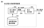
- 1 is a diagram showing an internal configuration of an independent power system management apparatus 101 according to an embodiment.
- 11 is a flow diagram illustrating a determination sequence when determining the closing order of section switches in a closing order determination unit 202 according to the embodiment.
- FIG. FIG. 11 is a diagram (part 1) for explaining a flow of determining a putting-in order by a putting-in order determination unit 202 according to the embodiment.
- FIG. 2 is a diagram (part 2) illustrating a flow of determining the putting-in order by the putting-in order determination unit 202 according to the embodiment.
- 11 is a diagram illustrating an example of a loading sequence table according to an embodiment.
- FIG. 1 is a diagram showing the overall configuration of an independent power system managed by an independent power system management device according to an embodiment.
- the independent power system management device 101 is a device that collects information on the operating state of the independent power system, performs necessary calculation processing, and transmits commands to each component in order to manage the operating state of the independent power system. The detailed configuration and operation will be described later.
- the power generation and substation facilities 102a to 102c are facilities that have power sources that supply power to the independent power system, and are connected to each other via a power transmission and distribution network.
- the power generation and substation facilities 102 may be distribution substations, mega solar facilities, wind power plants, or battery storage facilities.
- the voltage source power supplies 103a to 103c are power supplies capable of maintaining the system voltage, and may be rotating machine generators, or a combination of a power conversion device that implements control to maintain the AC system side voltage and a DC power supply.
- the DC power supply may be a storage battery, a solar panel, or a rectified output from a wind power generator.
- there is at least one voltage source power supply in the independent power system and any number of voltage source power supplies may be more than one.
- a function for synchronizing the voltage phases of the multiple voltage source power supplies is required, and this function may be realized by the oscillation characteristics of the rotating machine generator, or may be realized by a power conversion device that simulates operating characteristics similar to the oscillation characteristics of the rotating machine generator.
- the distributed power sources 104a to 104g are current source power sources that do not have the ability to maintain the grid voltage, but read the phase of the grid voltage and control the current flowing in and out while following it, and may be a storage battery system, a solar power generation system, or a wind power generation system. In the configuration according to the first embodiment, there may be multiple distributed power sources 104a to 104g, or none at all.
- Transformers 105a to 105j are interconnection transformers installed between the voltage source power sources 103a to 103c and the distributed power sources 104a to 104g and the power transmission and distribution network.
- the switches 106a to 106j are power supply switches that determine the connection state between the voltage source power sources 103a to 103c and the distributed power sources 104a to 104g and the power transmission and distribution network in the power generation and substation facilities 102a to 102c. Note that all elements described as switches may be circuit breakers.
- Switches 107a-107c are sectional switches that determine the connection state between power generation/substation facilities 102a-102c and the power transmission/distribution network.
- switches 107a-107c desirably have a synchronization function.
- the synchronization function refers to a function that suppresses inrush current caused by the difference in voltage between both ends when the switch is closed by operating the switch so that it is allowed to be closed only when certain conditions are satisfied regarding the difference in amplitude, phase, and frequency of the voltages at both ends when voltages supplied by different voltage source power sources are applied to both ends of the switch when the switch is closed from the cutoff state.
- Switches 108a to 108f are section switches installed to separate and manage the power transmission and distribution network of the autonomous power system.
- Transformers 109a to 109f are transformers installed so that consumers can receive voltage from the power transmission and distribution network, and may be pole-mounted transformers that are generally installed on the power distribution network, or receiving transformers that are installed on the premises of high-voltage consumers. While one transformer is shown per distribution section in FIG. 1, there may be multiple transformers or no transformers at all within one distribution section.
- the SVR110 is an automatic voltage regulator (Step Voltage Regulator), an autotransformer that adjusts voltage according to tide flow conditions by switching between multiple taps with different transformation ratios.
- Switch 111 is a switch that determines the connection state between the independent power system and the main grid, and is always in a disconnected state when operating independently, and is connected when operating in a grid-connected state with the main grid.
- the power generation and substation facility 102a is used as an example.
- the switch 107a is set to an off state and isolated from the power transmission and distribution network.
- the voltage source power supply 103a is started up to output a voltage.
- the voltage source power supply 103a may perform a soft start.
- a soft start refers to a startup method that avoids a sudden change in output voltage by gradually increasing the amplitude of the output AC voltage of the voltage source power supply from 0 to the rated voltage in a ramp or step-like manner over a period of several seconds to several minutes. If the switches 106a to 106d are turned on after the voltage source power supply 103a is started, a voltage may be suddenly applied to the transformers 105b to 105d, causing an excitation inrush current. To avoid this, the switches 106a to 106d may be turned on before the voltage source power supply 103a is soft-started. In this way, the change in the voltage applied to the transformers 105b to 105d also becomes gentle, and the occurrence of excitation inrush current can be suppressed.
- the interconnected operation of the distributed power sources 104a to 104c may or may not be started as necessary. This completes the start-up of the system within the power generation and substation facility 102a. In the same manner, the on-site systems of the power generation and substation facilities 102b and 102c can be started.
- sectional switches 107a to 107c and 108a to 108f are closed in sequence.
- the section to which voltage is supplied is expanded.
- the autonomous power system management device 101 determines and distributes the order in which the section switches are closed in this process.
- This excitation inrush current is shared and supplied by all voltage source power sources electrically connected to the transformer, but if the current borne by a certain voltage source power source is excessive compared to the capacity of the voltage source power source, there is a possibility that the voltage source power source will be stopped for overcurrent protection or a momentary voltage drop that deviates from the quality standard will occur. Therefore, in the embodiment, a method for determining the order in which sectional switches are closed is provided so that the voltage source power source can supply the excitation inrush current generated in the transformer when the sectional switch is closed with as much leeway as possible.
- the order in which the sectional switches are closed is determined so that the total capacity of the voltage source power supplies that will supply the magnetizing inrush current is greater than the total rated capacity of the transformers in which magnetizing inrush current may occur when the sectional switches are closed.
- the method for determining the order in which the sectional switches are closed is described in more detail below.
- FIG. 2 is a diagram showing the internal configuration of the independent power system management device 101 according to the embodiment. The configuration and operation of the independent power system management device 101 will be described with reference to FIG. 2.
- the power transmission and distribution system configuration information 201 includes information on the route of the power transmission and distribution system, the installation position of each section switch, the connection position and capacity of the transformers connected to each section, and the installation position and capacity of each voltage source power source.
- the independent power system management device 101 may, as an example, include an internal storage unit that stores the power transmission and distribution system configuration information 201, or it may be stored in an external storage medium and called up as needed.
- the closing sequence determination unit 202 determines the closing sequence of each sectional switch installed in the power transmission and distribution network based on at least the power transmission and distribution system configuration information 201, and transmits this to the closing command unit 203 as closing sequence information 204.
- the closing command unit 203 transmits a closing command 205 to each section switch based on the input closing sequence information 204.
- the closing command 205 may be transmitted via an electrical communication line or wirelessly.
- the command may also pass through a relay device on the path until it reaches the section switch, or through another management device that performs different processing.
- the independent power system management device 101 may, of course, also include in parallel a section that performs processing different from the processing described in this disclosure, such as determining the power value to be output by each distributed power source connected to the independent power system and whether to operate or stop the distributed power source, and transmitting an output power command value and an operation/stop command to each power source.
- FIG. 3 is a flow diagram illustrating the determination sequence when determining the closing order of the section switches in the closing order determination unit 202 according to the embodiment.
- the closing order of the sectional switches is determined so as to observe the following rules, which provides the effect of preventing overcurrent protection shutdown of the voltage source power source and excessive momentary voltage drops caused by excitation inrush currents to the transformer.
- Rules R1-R5 for determining the closing sequence of the sectional switches are defined as follows: Rule R1: A switch with no voltage on either side shall not be closed.
- Rule R3 When a switch with voltage applied to both sides is closed, it must be closed synchronously.
- Rule R4 If the sum of the "number of times synchronization has already been performed" and the "number of switches with synchronization function that have not been closed” is equal to the number of voltage source power sources included in the autonomous power system (N) - 1, normal closing of switches with synchronization function that have not been closed is prohibited.
- the X value is the total capacity of the group of transformers included in the transmission and distribution section to which voltage is newly applied by closing the target sectional switch, divided by the total capacity of the voltage source power sources that are already electrically connected to the sectional switch.
- Rule R1 First, even if a sectional switch with no voltage on both sides is closed, the power supply section does not expand. Also, when other sectional switches are closed normally in a subsequent process, the area to which voltage is applied at the same time becomes wider, so the number of transformers to which voltage is applied at one time increases, which may be disadvantageous in terms of the amount of magnetizing inrush current generated. The constraint to avoid this is rule R1.
- Rule R2 is a characteristic element of the present disclosure.
- a section switch When a section switch is normally turned on, a new voltage is applied to the transformer, generating an excitation inrush current, which is supplied by the voltage source power supply.
- the amount of excitation inrush current generated by a transformer is proportional to the rated capacity of the transformer if the voltage phase, residual magnetic flux, and excitation characteristics are the same.
- the power supply supplies the total value.
- there is a limit value of the current that can be supplied to all power supplies, and in order to prevent equipment from breaking down when this limit is reached, a certain overcurrent tolerance is set, and if this limit is exceeded, the equipment is generally stopped to protect it.
- the overcurrent tolerance of a voltage source power supply varies greatly depending on whether it is a rotating machine power supply or an inverter power supply, it is proportional to the rated capacity if it is the same type of power supply.
- the current is shared and supplied according to the ratio of their rated capacities, the ratio of the impedance of the distribution line, etc. Therefore, the smaller the X value, i.e., the value obtained by dividing the total capacity of the transformer group to which the voltage is newly applied by the total capacity of the voltage source power source, the less likely it is to cause an overcurrent protection stop and a voltage drop, since each voltage source power source can supply current with a margin relative to its own rating.
- the threshold value in advance.
- the amount of excitation inrush current generated in a transformer varies each time depending on the voltage phase, residual magnetic flux, and excitation characteristics, so it is desirable to assume the most severe conditions, and derive in advance an upper limit value of the X value by desk calculation or simulation such that the current supplied by the voltage source power source falls within the allowable range even under these conditions, and the amount of voltage drop falls within the allowable range, and set this as the threshold value.
- Rule R3 restricts the operation to always synchronize when paths of voltages supplied from different voltage source power sources join together. If a switch is closed when the voltages at both ends of a switch that is not closed are significantly different, an inrush current or a sudden voltage fluctuation occurs, so this rule reflects the need to synchronize as a countermeasure against this.
- Rule R4 is a constraint that takes into consideration the fact that, in satisfying rule R3, synchronization can only be performed by sectional switches having a synchronization function. If synchronization is always performed when electrical paths connected from different voltage source power sources join together, synchronization must be performed a total of N-1 times to complete the connection of all sections of an autonomous power system that includes N voltage source power sources. However, since synchronization can only be performed by sectional switches having a synchronization function, in any given situation, it is necessary to satisfy (number of times synchronization has already been performed) + (number of sectional switches having a synchronization function that have not yet been activated) ⁇ N-1.
- Rule R4 has the effect of preventing situations in which rule R3 cannot be satisfied.
- Rule R5 As long as rule R2 exists, it is desirable to determine the input sequence so as to reduce the X value. In order to reduce the X value, it is desirable to increase the total capacity of the voltage source power supplies that supply the magnetizing inrush current, since the total capacity of the transformers in a certain section has already been determined by the equipment configuration. In other words, it is desirable to first ensure that multiple voltage source power supplies are connected in parallel. Since performing synchronous input is synonymous with connecting different voltage source power supplies in parallel, giving priority to synchronous input over normal input has the effect of reducing the X value.
- Figure 3 shows a sequence for determining the switch closing order that complies with the above rules R1-R5.
- the closing sequence determination unit 202 executes the voltage rise operation for each internal system of the facility (step S0). Note that in this example, a case where the voltage rise operation for each internal system of the facility is executed is described, but the rise operation may be actually executed after the switch closing sequence is determined.
- the turn-on sequence determination unit 202 initializes the turn-on sequence table (step S2).
- the turn-on sequence table is a table in which the turn-on sequence of the section switches is arranged in order from the beginning, and contents are added and deleted each time processing is performed.
- the closing sequence determination unit 202 updates the virtual voltage application area based on the closing state of each sectional switch in the closing sequence table (step S4).
- the closing sequence determination unit 202 refers to information in the current contents of the closing sequence table as to whether each sectional switch has been closed or not, and confirms and updates which area in the power transmission and distribution network has voltage applied to it.
- the closing order determination unit 202 identifies sectional switches that are candidates for closing according to the updated voltage application area (step S6). Specifically, the closing order determination unit 202 identifies all sectional switches that have not been closed and have voltage applied to at least one side, and designates them as sectional switches that are candidates for closing. Rule R1 is observed by selecting the sectional switches to be closed from the sectional switches that are candidates for closing determined in this way.
- the closing order determination unit 202 specifies a sectional switch capable of being closed in synchronization from among the identified sectional switches that are candidates for closing (step S8). Specifically, the closing order determination unit 202 specifies a sectional switch that has voltage applied to both sides and has a synchronous closing function from among the sectional switches that are candidates for closing. Rule R3 is observed by selecting a sectional switch to be closed in synchronization from among the sectional switches that can be closed in synchronization.
- the closing sequence determination unit 202 calculates the X value (step S9).
- the X value is the total capacity of the transformers included in the transmission and distribution section to which a new voltage is applied by closing the target sectional switch, divided by the total capacity of the voltage source power sources that are already electrically connected to the sectional switch.
- the closing order determination unit 202 designates all sectional switches that satisfy X value ⁇ threshold as sectional switches that can be closed normally (step S10). Specifically, the closing order determination unit 202 designates all sectional switches that have voltage applied to only one side and satisfy X value ⁇ threshold as sectional switches that can be closed normally among the sectional switches that are candidates for closing. Rule R2 is observed by selecting sectional switches to be closed normally from among the sectional switches that can be closed normally.
- the closing sequence determination unit 202 determines whether there are any section switches that can be closed synchronously (step S12).
- step S12 if the closing sequence determination unit 202 determines that there are sectional switches that can be synchronized (YES in step S12), it selects one of the sectional switches that can be synchronized and adds it to the closing sequence table (synchronized closing).
- the closing sequence determination unit 202 determines that there are sectional switches that can be synchronized (YES in step S12)
- it may be selected randomly from among all sectional switches that can be synchronized, or it may be selected according to some rule, such as ascending order of management numbers.
- step S16 the closing sequence determination unit 202 determines whether all section switches have been added to the closing sequence table (step S16).
- the closing order determination unit 202 determines in step S16 that all sectional switches have been added to the closing order table (YES in step S16), it confirms the closing order (step S30). After the closing order of all sectional switches has been determined, it actually outputs a closing command. This is because there is a possibility that, by closing a certain sectional switch first, a situation may arise in which there are sectional switches that have not been closed in a subsequent process but there are no sectional switches that can be closed, and it may be necessary to return to the previous state. In other words, the closing order determination unit 202 generates a closing order table in which it has been confirmed that it is possible to close all sectional switches, and then outputs it to the closing command unit 203.
- the input sequence determination unit 202 ends the process. In other words, it outputs the confirmed input sequence table to the input command unit 203 as input sequence information 204.
- step S16 if the closing sequence determination unit 202 determines that not all sectional switches have been added to the closing sequence table (NO in step S16), it returns to step S4 and repeats the above process until all sectional switches have been added to the closing sequence table.
- step S12 determines in step S12 that there are no sectional switches that can be closed synchronously (NO in step S12), it determines whether there are any sectional switches that can be closed normally (step S18).
- step S18 the closing sequence determination unit 202 determines that there are no section switches that can be closed normally (NO in step S18), the process returns to step S2. In other words, the closing sequence table is initialized.
- the switching order determination unit 202 may store the list of the switching order table before initialization in order to avoid repeating the same process, and may perform control to specify an order other than that. In other words, if a situation arises in which there are sectional switches that have not been switched on but no sectional switches that can be switched on, the determination is to be restarted from the beginning. In this way, the determination can be repeated until the switching order for all sectional switches is determined.
- step S18 if the closing order determination unit 202 determines that there are sectional switches that can be closed normally (YES in step S18), it selects one of the sectional switches that can be closed normally (step S20).
- selecting one of the sectional switches that can be closed normally it may be selected randomly from among all sectional switches that can be closed normally, or it may be selected according to some rule, such as ascending order of management numbers.
- the closing sequence determination unit 202 determines whether the selected section switches that can be closed normally have a synchronous closing function (step S22).
- step S22 if the closing sequence determination unit 202 determines that the selected normally openable section switch does not have a synchronous closing function (NO in step S22), it adds the selected normally installable section switch to the closing sequence table (normal closing) (step S28).
- step S22 if the closing order determination unit 202 determines that the selected section switch that can be normally closed has a synchronization closing function (YES in step S22), it determines whether or not the condition of "number of synchronization closings + number of section switches that can be synchronized but have not been closed >N-1" is satisfied (step S24).
- step S24 if the closing sequence determination unit 202 determines that the condition of "number of synchronous closings + number of sectional switches that can be closed and that have not been closed > N-1" is met (YES in step S24), the process proceeds to step S28, where the selected sectional switches that can be normally installed are added to the closing sequence table (normal closing). Subsequent processing is similar.
- step S24 if the closing sequence determination unit 202 determines that the condition of "number of times to close the synchronization + number of section switches that can be closed but have not been closed > N-1" is not met (NO in step S24), the process proceeds to step S26.
- step S26 the insertion sequence determination unit 202 excludes the selected section switches that can be normally installed. Then, the process returns to step S20 and the above process is repeated.
- FIG. 4 is a diagram (part 1) for explaining the flow of determining the closing order by the closing order determination unit 202 according to the embodiment. Note that in this explanation, it is assumed that the sectional switches 107a to 107c have a synchronous closing function, and the sectional switches 108a to 108f do not have a synchronous closing function.
- step S0 the power-on sequence determination unit 202 executes the voltage startup operation for each facility's internal system. This applies voltage to one side of the sectional switches 107a, 107b, and 107c.
- step S2 the supply sequence determination unit 202 initializes the supply sequence table.
- step S4 the supply sequence determination unit 202 updates the virtual voltage application area.
- sectional switches 107a, 107b, and 107c are candidates for normal switching. Note that sectional switches 107a, 107b, and 107c satisfy the condition that X value is less than the threshold value.
- step S20 it is assumed that the section switch 107b that can be normally closed is selected.
- the selected section switch 107b has a synchronization function, so proceed to step S24.
- step S24 the section switch 107b selected because it satisfies the condition of "number of times to synchronize + number of section switches that can be synchronized but not yet switched on > N-1" is added to the switching order table (normal switching). Then, the process returns to step S4.
- the closing sequence determination unit 202 updates the virtual voltage application area.
- sectional switches 107a, 107c, and 108c are candidates for normal closing. Note that sectional switches 107a, 107b, and 108c are assumed to satisfy the condition that X value is less than the threshold value.
- step S20 it is assumed that the section switch 107a that can be normally closed is selected.
- the selected section switch 107a has a synchronization function, so proceed to step S24.
- step S24 the section switch 107a selected because it does not satisfy the condition of "number of times synchronized + number of unsynchronized section switch units that can be synchronized > N-1" is excluded from the section switches that can be normally switched on. Then, proceed to step S20.
- step S20 it is assumed that the normally openable section switch 107c is selected again.
- the selected section switch 107c has a synchronization function, so proceed to step S24.
- step S24 the section switch 107c selected because it does not satisfy the condition "number of times synchronized + number of unsynchronized section switch units that can be synchronized > N-1" is excluded from the section switches that can be normally switched on. Then, proceed to step S20.
- step S20 it is assumed that the normally openable section switch 108c is selected again.
- the selected section switch 108c does not have a synchronization function, so proceed to step S28.
- Section switch 108c is added to the closing sequence table (normal closing). Then, the process returns to step S4.
- the closing sequence determination unit 202 updates the virtual voltage application area.
- sectional switches 107a, 107c, 108b, 108e, and 108f are candidates for normal switching.
- sectional switches 107a, 107c, 108b, and 108f are assumed to satisfy X value ⁇ threshold.
- sectional switch 108e is assumed to not satisfy X value ⁇ threshold.
- step S20 it is assumed that the section switch 108f that can be normally closed is selected.
- the selected section switch 108f does not have a synchronization function, so proceed to step S28.
- Section switch 108f is added to the closing sequence table (normal closing). Then, the process returns to step S4.
- the closing sequence determination unit 202 updates the virtual voltage application area.
- sectional switch 107c capable of synchronous switching and sectional switches 107a, 108b, and 108e are candidates for normal switching. Note that sectional switches 107a, 108b, and 108e are assumed to satisfy the condition that X value is less than the threshold value.
- step S12 since there is a sectional switch 107c that can be synchronized, the sectional switch 107c is added to the closing sequence table (synchronized closing). Then, the process returns to step S4.
- the closing sequence determination unit 202 updates the virtual voltage application area.
- sectional switches 107a and 108b are candidates for normal switching. Note that sectional switches 107a and 108b satisfy X value ⁇ threshold. Meanwhile, sectional switch 108e does not satisfy X value ⁇ threshold.
- step S20 it is assumed that the section switch 108b that can be normally closed is selected.
- the selected section switch 108b does not have a synchronization function, so proceed to step S28.
- Section switch 108b is added to the closing sequence table (normal closing). Then, the process returns to step S4.
- the closing sequence determination unit 202 updates the virtual voltage application area.
- sectional switches 107a and 108a are candidates for normal switching. Note that sectional switches 107a and 108a satisfy the condition X value ⁇ threshold. Meanwhile, sectional switch 108e does not satisfy the condition X value ⁇ threshold.
- step S20 it is assumed that the section switch 108a that can be normally closed is selected.
- the selected section switch 108a does not have a synchronization function, so proceed to step S28.
- Section switch 108a is added to the closing sequence table (normal closing). Then, the process returns to step S4.
- the closing sequence determination unit 202 updates the virtual voltage application area.
- FIG. 5 is a diagram (part 2) explaining the flow of determining the input order by the input order determination unit 202 according to the embodiment.
- FIG. 5(A) a case is shown in which there is a sectional switch 107a that can be synchronized. Note that the sectional switch 107a satisfies X value ⁇ threshold. On the other hand, the sectional switch 108e does not satisfy X value ⁇ threshold.
- step S12 since there is a sectional switch 107a that can be synchronized, the sectional switch 107a is added to the closing sequence table (synchronized closing). Then, the process returns to step S4.
- the closing sequence determination unit 202 updates the virtual voltage application area.
- sectional switch 108e is the candidate for normal switching. Note that sectional switch 108e satisfies X value ⁇ threshold.
- step S20 it is assumed that the section switch 108e that can be normally closed is selected.
- the selected section switch 108e does not have a synchronization function, so proceed to step S28.
- Section switch 108e is added to the closing sequence table (normal closing). Then, the process returns to step S4.
- the closing sequence determination unit 202 updates the virtual voltage application area.
- sectional switch 108d is the candidate for normal switching. Note that sectional switch 108d satisfies X value ⁇ threshold.
- step S20 it is assumed that the section switch 108d that can be normally closed is selected.
- the selected section switch 108d does not have a synchronization function, so proceed to step S28.
- the section switch 108d is added to the closing sequence table (normal closing). As a result, all the sectioning switches are added to the closing sequence table as shown in Fig. 5(D), and the process is then completed.
- FIG. 6 is a diagram illustrating an example of a loading sequence table according to the embodiment. 6 shows a case where the following sections are added to the closing sequence: sectional switch 107b (normal closing) as the first, sectional switch 108c (normal closing) as the second, sectional switch 108f (normal closing) as the third, sectional switch 107c (synchronized closing) as the fourth, sectional switch 108b (normal closing) as the fifth, sectional switch 108a (normal closing) as the sixth, sectional switch 107a (synchronized closing) as the seventh, sectional switch 108e (normal closing) as the eighth, and sectional switch 108d (normal closing) as the ninth.
- this closing sequence table is an example, and the closing sequence may be based on other combinations according to the above flow.
- the autonomous power system management device which manages the closing order of the sectional switches according to the method for determining the closing order of the sectional switches described above, has the effect of preventing overcurrent protection stoppage of the voltage source power supply that supplies the excitation inrush current that flows into the transformer when the sectional switches are closed and preventing excessive momentary voltage drops in the transmission and distribution system when starting up the autonomous power system from a power outage state.
- the sectional switch whose X value is smaller than the threshold value is preferentially closed, but this is not limited to the above.
- the closing priority of the sectional switch may be determined by another method using information on the total capacity value of the transformer group included in the transmission/distribution section and the total capacity value of the voltage source power sources already electrically connected to the sectional switch. For example, the closing priority may be determined by determining whether the difference obtained by subtracting the total capacity value of the transformer group included in the transmission/distribution section from the total capacity value of the voltage source power sources already electrically connected to the sectional switch is greater than a certain threshold value.
- 101 Independent power system management device 102, 102a, 102b, 102c Substation facility, 103, 103a, 103b, 103c Voltage source power source, 104, 104a, 104c, 104g Distributed power source, 107a, 107b, 107c, 108a, 108b, 108c, 108d, 108e, 108f section switch, 201 power transmission and distribution system configuration information, 202 closing order determining unit, 203 closing command unit.
Landscapes
- Engineering & Computer Science (AREA)
- Power Engineering (AREA)
- Supply And Distribution Of Alternating Current (AREA)
- Remote Monitoring And Control Of Power-Distribution Networks (AREA)
Abstract
Description
図1は、実施の形態に従う自立電力系統管理装置が管理する自立電力系統全体の構成を示す図である。
自立電力系統管理装置101は、自立電力系統の運転状態を管理すべく、自立電力系統の運転状態に関する情報を収集し、必要な演算処理を行い、各構成要素に指令を送信する装置である。詳細な構成及び動作は後述する。
以下の説明では、未投入であり片側のみに電圧が印加されておりもう片側が無電圧である区分開閉器を投入することを「通常投入」とよぶ。また、未投入であり両側に電圧が印加されている区分開閉器を、両端子電圧の振幅・位相等の同期を確認した状態で投入することを「同期投入」とよぶ。
ルールR1:両側ともに無電圧である開閉器は投入しない。
ルールR4:「既に同期投入を行った回数」と「同期投入機能を有する未投入の開閉器の台数」の合計が、自立電力系統に含まれる電圧源電源の台数(N)-1に等しい場合は、同期投入機能を有する未投入の開閉器を通常投入することを禁止する。
(1)ルールR1
第一に、両側が無電圧である区分開閉器を投入しても電力供給区間が拡大しない。また、その後の工程において他の区分開閉器を通常投入した際に新たに同時に電圧が印加される範囲が広くなるため、一度に電圧がかかる変圧器の台数が増加し、励磁突入電流の発生量の面で不利となる場合がある。これを回避するための制約がルールR1となる。
ルールR2は、本開示の特徴となる要素である。区分開閉器を通常投入すると、新たに変圧器に電圧が印加され励磁突入電流が発生し、これを電圧源電源が供給する。一般に、変圧器の励磁突入電流の発生量は、電圧位相や残留磁束、励磁特性が同一条件であれば変圧器の定格容量に比例する。また、並列して接続される複数の変圧器において同時に励磁突入電流が発生するときは、その合計値を電源が供給することとなる。一方、全ての電源には供給できる電流の限界値が存在し、これに至って機器が故障することを避けるために、一定の過電流耐量を設け、これを逸脱した場合には機器を保護するために停止させることが一般的である。電圧源電源の過電流耐量は、回転機電源かインバータ系電源かの別により大きく異なるものの、同一種の電源であれば定格容量に比例する。また、電圧源電源が複数並列している場合は、その定格容量の比や、配電線のインピーダンスの比等に応じて、分担して電流を供給する。したがって、X値、すなわち、新たに電圧が印加される変圧器群の容量合計値を、電圧源電源の容量合計値で除した値が小さいほど、各電圧源電源は自己定格に対して余裕を持った電流供給が可能であるため、過電流保護停止に至りにくく、電圧低下も発生しにくい。そこで、X値が一定の閾値より小さい区分開閉器のみを通常投入するように制限することにより、電圧源電源の過電流保護停止や過度な電圧低下を予防できる効果が得られる。閾値は、事前に決定しておくことが望ましい。前述の通り、変圧器での励磁突入電流の発生量は、電圧位相や残留磁束、励磁特性によって都度ばらつくため、最も過酷な条件を想定したうえで、この条件においても電圧源電源の供給する電流が許容範囲に入り、かつ、電圧低下の量が許容範囲に収まるようなX値の上限値を、机上計算またはシミュレーションによって事前に導出し、これを閾値として設定しておくことが望ましい。
ルールR3では、異なる電圧源電源から供給される電圧の経路どうしが合流する際に必ず同期投入を実施するよう制限している。未投入の開閉器の両端の電圧が大きく異なる状態で開閉器を投入すると、突入電流や急激な電圧変動が発生するため、この対策として同期投入を行うことを反映したルールとなる。
ルールR4は、ルールR3を満足するうえで、同期投入機能を有した区分開閉器においてしか同期投入が実施できないことを考慮した制約である。異なる電圧源電源から接続される電気的経路どうしが合流する時には必ず同期投入を行うのであれば、電圧源電源をN台含む自立電力系統の全区域の接続を完了するには、同期投入を合計N-1回実施することが必要となる。しかしながら、同期投入機能を有した区分開閉器によってしか同期投入が実施できないため、任意の局面において、(既に同期投入を行った回数)+(同期投入機能を有する未投入の区分開閉器台数)≧N-1が満たされる必要がある。
ルールR2が存在する以上、X値が小さくなるように投入順序を決定することが望ましい。X値を小さくするためには、ある区間に存在する変圧器の容量合計値は設備構成によって既に決定しているため、励磁突入電流を供給する電圧源電源の容量合計値を大きくすることが望ましい。すなわち、複数の電圧源電源を並列した状態を先に確保することが望ましい。同期投入を行うことは、異なる電圧源電源を並列することと同義であるため、通常投入よりも同期投入を優先的に実施することで、X値を小さくできる効果がある。
一方、ステップS22において、投入順序決定部202は、選択した通常投入可能な区分開閉器は同期投入機能を有していると判断した場合(ステップS22においてYES)には、同期投入回数+未投入の同期投入可能な区分開閉器の台数>N-1の条件を満たしているか否かを判断する(ステップS24)。
これにより、図5(D)に示されるように全ての区分開閉器が投入順序表に追加された状態となる。これにより処理を終了する。
図6を参照して、投入順序の1番目として区分開閉器107b(通常投入)、2番目として区分開閉器108c(通常投入)、3番目として区分開閉器108f(通常投入)、4番目として区分開閉器107c(同期投入)、5番目として区分開閉器108b(通常投入)、6番目として区分開閉器108a(通常投入)、7番目として区分開閉器107a(同期投入)、8番目として区分開閉器108e(通常投入)、9番目として区分開閉器108d(通常投入)が追加された場合が示されている。なお、当該投入順序表は一例であり、上記フローにしたがって他の組み合わせに基づく投入順序ともなり得る。
Claims (8)
- 基幹電力系統から解列されて独立的に運用される自立電力系統の運用状態を管理する自立電力系統管理装置において、
前記自立電力系統は、系統電圧を維持するように機能する電圧源電源を少なくとも1台含むとともに、前記電圧源電源と各需要家とを相互に電気的に接続するネットワークを形成する送配電網との接続ならびに前記送配電網を区分けする複数の区分開閉器とを含み、
前記自立電力系統管理装置は、
前記送配電網の経路情報と、各送配電区間に含まれる変圧器の容量情報と、各前記電圧源電源の容量情報とに基づき、前記自立電力系統が停電状態から復電する際の前記複数の区分開閉器の投入順序を決定する投入順序決定部と、
前記投入順序決定部が決定した順序に従って前記複数の区分開閉器に投入指令を与える投入指令部とを備え、
前記投入順序決定部は、未投入の区分開閉器のうち、ある区分開閉器を投入することで新たに電圧が印加される送配電区間が存在する場合に、前記送配電区間に含まれる変圧器群の容量合計値と、当該区分開閉器と既に電気的に接続状態にある電圧源電源の容量合計値の情報とに基づいて、当該区分開閉器の投入優先順位を決定する、自立電力系統管理装置。 - 前記投入順序決定部は、未投入の区分開閉器のうち、ある区分開閉器を投入することで新たに電圧が印加される送配電区間が存在する場合に、前記送配電区間に含まれる変圧器群の容量合計値を、当該区分開閉器と既に電気的に接続状態にある電圧源電源の容量合計値で除した値が、あらかじめ定めた閾値より小さくなる当該区分開閉器を通常投入可能開閉器とし、前記通常投入可能開閉器をその他の区分開閉器より優先的に投入するように投入順序を決定する、請求項1記載の自立電力系統管理装置。
- 前記投入順序決定部は、未投入の区分開閉器のうち、ある区分開閉器の両端子に電圧が印加されており、かつ同期投入機能を有している当該区分開閉器を、同期投入可能開閉器とし、前記同期投入可能開閉器をその他の区分開閉器より優先的に投入するように投入順序を決定する、請求項2記載の自立電力系統管理装置。
- 前記投入順序決定部は、前記同期投入可能開閉器と、前記通常投入可能開閉器とがともに存在するとき、前記同期投入可能開閉器を優先的に投入するように投入順序を決定する、請求項3記載の自立電力系統管理装置。
- 前記自立電力系統に、前記電圧源電源が少なくとも2台以上含まれ、
前記投入順序決定部は、任意の電圧源電源から電気的に接続されている経路と異なる任意の電圧源電源から電気的に接続されている経路とがある区分開閉器の投入によって接続されるとき、前記区分開閉器は同期投入機能を有する区分開閉器となるように投入順序を決定する、請求項1~4のいずれか一項に記載の自立電力系統管理装置。 - 前記投入順序決定部は、前記自立電力系統に含まれる同期投入機能を有する開閉器のうち、前記自立電力系統に含まれる電圧源電源の総台数から1を減じた数と同じ台数は同期投入を行うように投入順序を決定する、請求項5記載の自立電力系統管理装置。
- 前記電圧源電源は、同期発電機の動作特性を模擬した制御を行うインバータ電源である、請求項1記載の自立電力系統管理装置。
- 基幹電力系統から解列されて独立的に運用される自立電力系統と、
前記自立電力系統の運用状態を管理する自立電力系統管理装置とを備え、
前記自立電力系統は、系統電圧を維持するように機能する電圧源電源を少なくとも1台含むとともに、前記電圧源電源と各需要家とを相互に電気的に接続するネットワークを形成する送配電網との接続状態ならびに前記送配電網を区分けする複数の区分開閉器とを含み、
前記自立電力系統管理装置は、
前記送配電網の経路情報と、各送配電区間に含まれる変圧器の容量情報と、各前記電圧源電源の容量情報とに基づき、前記自立電力系統が停電状態から復電する際の前記複数の区分開閉器の投入順序を決定する投入順序決定部と、
前記投入順序決定部が決定した順序に従って前記複数の区分開閉器に投入指令を与える投入指令部とを含み、
前記投入順序決定部が、未投入の区分開閉器のうち、ある区分開閉器を投入することで新たに電圧が印加される送配電区間が存在する場合に、前記送配電区間に含まれる変圧器群の容量合計値と、当該区分開閉器と既に電気的に接続状態にある電圧源電源の容量合計値の情報とに基づいて、当該区分開閉器の投入優先順位を決定する、自立電力系統システム。
Priority Applications (3)
| Application Number | Priority Date | Filing Date | Title |
|---|---|---|---|
| PCT/JP2023/006158 WO2024176331A1 (ja) | 2023-02-21 | 2023-02-21 | 自立電力系統管理装置および自立電力系統システム |
| JP2025501959A JPWO2024176331A1 (ja) | 2023-02-21 | 2023-02-21 | |
| TW113103919A TWI890300B (zh) | 2023-02-21 | 2024-02-01 | 自立電力系統管理裝置以及自立電網系統 |
Applications Claiming Priority (1)
| Application Number | Priority Date | Filing Date | Title |
|---|---|---|---|
| PCT/JP2023/006158 WO2024176331A1 (ja) | 2023-02-21 | 2023-02-21 | 自立電力系統管理装置および自立電力系統システム |
Publications (1)
| Publication Number | Publication Date |
|---|---|
| WO2024176331A1 true WO2024176331A1 (ja) | 2024-08-29 |
Family
ID=92500368
Family Applications (1)
| Application Number | Title | Priority Date | Filing Date |
|---|---|---|---|
| PCT/JP2023/006158 Ceased WO2024176331A1 (ja) | 2023-02-21 | 2023-02-21 | 自立電力系統管理装置および自立電力系統システム |
Country Status (3)
| Country | Link |
|---|---|
| JP (1) | JPWO2024176331A1 (ja) |
| TW (1) | TWI890300B (ja) |
| WO (1) | WO2024176331A1 (ja) |
Citations (3)
| Publication number | Priority date | Publication date | Assignee | Title |
|---|---|---|---|---|
| JP2009148098A (ja) * | 2007-12-14 | 2009-07-02 | Toshiba Corp | 配電線自動制御システム、並びに配電線自動制御方法およびプログラム |
| JP2012090386A (ja) * | 2010-10-18 | 2012-05-10 | Chugoku Electric Power Co Inc:The | 配電線転負荷可否判定システム |
| JP2022169170A (ja) * | 2021-04-27 | 2022-11-09 | 株式会社日立製作所 | 単独運転系統構成装置、単独運転系統構成システム、および単独運転系統構成方法 |
Family Cites Families (6)
| Publication number | Priority date | Publication date | Assignee | Title |
|---|---|---|---|---|
| JPH06319229A (ja) * | 1993-04-30 | 1994-11-15 | Fuji Electric Co Ltd | 自動力率調整装置 |
| JP2006121846A (ja) * | 2004-10-22 | 2006-05-11 | Toshiba Corp | 系統併入システム |
| JP2011114956A (ja) * | 2009-11-27 | 2011-06-09 | Hitachi Ltd | マイクログリッドの安定運転制御装置 |
| WO2016021179A1 (ja) * | 2014-08-04 | 2016-02-11 | 日本電気株式会社 | 分散電源システム、局制御装置、制御方法およびプログラムが記憶された記憶媒体 |
| CN110266044B (zh) * | 2019-06-24 | 2021-12-07 | 国网内蒙古东部电力有限公司电力科学研究院 | 一种基于储能变流器的微电网并网控制系统及方法 |
| CN110707759B (zh) * | 2019-11-07 | 2021-04-30 | 北京四方继保自动化股份有限公司 | 一种风电高比例电网安全稳定控制方法 |
-
2023
- 2023-02-21 WO PCT/JP2023/006158 patent/WO2024176331A1/ja not_active Ceased
- 2023-02-21 JP JP2025501959A patent/JPWO2024176331A1/ja active Pending
-
2024
- 2024-02-01 TW TW113103919A patent/TWI890300B/zh active
Patent Citations (3)
| Publication number | Priority date | Publication date | Assignee | Title |
|---|---|---|---|---|
| JP2009148098A (ja) * | 2007-12-14 | 2009-07-02 | Toshiba Corp | 配電線自動制御システム、並びに配電線自動制御方法およびプログラム |
| JP2012090386A (ja) * | 2010-10-18 | 2012-05-10 | Chugoku Electric Power Co Inc:The | 配電線転負荷可否判定システム |
| JP2022169170A (ja) * | 2021-04-27 | 2022-11-09 | 株式会社日立製作所 | 単独運転系統構成装置、単独運転系統構成システム、および単独運転系統構成方法 |
Also Published As
| Publication number | Publication date |
|---|---|
| TWI890300B (zh) | 2025-07-11 |
| TW202441871A (zh) | 2024-10-16 |
| JPWO2024176331A1 (ja) | 2024-08-29 |
Similar Documents
| Publication | Publication Date | Title |
|---|---|---|
| TWI802597B (zh) | 一種黑啟動電網的方法 | |
| Lopes et al. | Microgrids black start and islanded operation | |
| CN111052529B (zh) | 电源系统 | |
| Balog et al. | The load as an energy asset in a distributed DC smartgrid architecture | |
| Bahrman et al. | The new black start: System restoration with help from voltage-sourced converters | |
| US10578082B2 (en) | Method and controller for coordinating control of wind farm during disconnection to utility grid | |
| CN100550572C (zh) | 稳定化电力供给系统及其运用方法、以及电力稳定供给的运用工序 | |
| CN104917278B (zh) | 冗余不间断电源系统 | |
| CN105322642B (zh) | 用于开发在静态ups中的电流容量的系统和方法 | |
| Luscan et al. | A vision of HVDC key role toward fault-tolerant and stable AC/DC grids | |
| WO2024249990A1 (en) | System and method for automated clean energy blackstart for backup auxiliary power, microgrid customer loads, and utility grid | |
| Kucuk | Intelligent electrical load shedding in heavily loaded industrial establishments with a case study | |
| Zhan et al. | Assuring security and stability of a remote/islanded large electric power system with high penetration of variable renewable energy resources | |
| JP2024027338A (ja) | 電力供給ネットワークおよび電力供給方法 | |
| WO2024176331A1 (ja) | 自立電力系統管理装置および自立電力系統システム | |
| Enacheanu et al. | New control strategies to prevent blackouts: Intentional islanding operation in distribution networks | |
| AU2021363036B2 (en) | Electrical substation, a method of operating thereof, and a use thereof | |
| Barker et al. | Completing the Circuit: Integration of Offshore Wind Farms into the Grid using High Voltage dc Technology | |
| Ahmed et al. | BESS Assisted Frequency Management for Black Start Process of Microgrid | |
| Quaia et al. | Using pumped storage loads in restoration paths: a field test in the Italian national grid | |
| RU2784610C1 (ru) | Способ децентрализованной синхронизации и восстановления нормального режима аварийно разделенной электрической сети с генераторами | |
| CA3194545C (en) | Electrical substation, a method of operating thereof, and a use thereof | |
| Megdiche et al. | Data Center Electrical Design | |
| Strunck et al. | A Study on the Black Start Process of a real Distribution Network with CHP plants and BESS | |
| Jiang et al. | A comparative study of master-slave control and virtual synchronous machine control for parallel VSC-HVDC links feeding passive loads on offshore platforms |
Legal Events
| Date | Code | Title | Description |
|---|---|---|---|
| 121 | Ep: the epo has been informed by wipo that ep was designated in this application |
Ref document number: 23923985 Country of ref document: EP Kind code of ref document: A1 |
|
| ENP | Entry into the national phase |
Ref document number: 2025501959 Country of ref document: JP Kind code of ref document: A |
|
| WWE | Wipo information: entry into national phase |
Ref document number: 2025501959 Country of ref document: JP |
|
| NENP | Non-entry into the national phase |
Ref country code: DE |
|
| 122 | Ep: pct application non-entry in european phase |
Ref document number: 23923985 Country of ref document: EP Kind code of ref document: A1 |