WO2024176319A1 - 対象領域抽出装置、方法、及びシステム - Google Patents
対象領域抽出装置、方法、及びシステム Download PDFInfo
- Publication number
- WO2024176319A1 WO2024176319A1 PCT/JP2023/006068 JP2023006068W WO2024176319A1 WO 2024176319 A1 WO2024176319 A1 WO 2024176319A1 JP 2023006068 W JP2023006068 W JP 2023006068W WO 2024176319 A1 WO2024176319 A1 WO 2024176319A1
- Authority
- WO
- WIPO (PCT)
- Prior art keywords
- area
- image data
- region
- unit
- product
- Prior art date
- Legal status (The legal status is an assumption and is not a legal conclusion. Google has not performed a legal analysis and makes no representation as to the accuracy of the status listed.)
- Ceased
Links
Images



Classifications
-
- G—PHYSICS
- G06—COMPUTING OR CALCULATING; COUNTING
- G06T—IMAGE DATA PROCESSING OR GENERATION, IN GENERAL
- G06T7/00—Image analysis
- G06T7/10—Segmentation; Edge detection
- G06T7/11—Region-based segmentation
Definitions
- This disclosure relates to a target area extraction device, method, and system.
- Patent Document 1 In manufacturing sites such as factories, products manufactured using industrial machines such as machining centers and robots are inspected (see, for example, Patent Document 1).
- target area target pixel area
- area detection methods used were to define an area as a region containing a set number of consecutive pixels with a certain brightness or higher, or to define the shape pattern of the inspection range in advance and perform pattern matching to define the area.
- the target area extraction device disclosed herein solves the above problem by extracting areas using a deep learning device that has been trained in advance by a neural network that divides areas into three or more classes for image data showing the target product, and extracting each area with greater accuracy.
- One aspect of the present disclosure is a target region extraction device that includes a model storage unit that stores a model of a neural network trained using multiple pieces of training image data in which image data obtained by capturing an image of a product is assigned different annotation information according to the type of the region for three or more regions with different characteristics in the image data, a data acquisition unit that acquires image data of an image of the product's appearance, a region extraction unit that uses the model stored in the model storage unit to extract three or more types of regions with different characteristics from the image data, a region-specific processing unit that performs region-specific processing on each region corresponding to the type of the region, and an output unit that outputs the results of processing by the region-specific processing unit.
- FIG. 1 is a hardware configuration diagram of a target region extraction device according to a first embodiment.
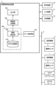
- 1 is a block diagram showing functions of a target region extraction device according to a first embodiment.
- 11 is a schematic diagram illustrating division of image data by a region extraction unit.
- FIG. 11 is a schematic diagram showing an example of area-by-area processing by an area-by-area processing unit.
- FIG. 11 is a block diagram showing functions of a target region extraction device according to a second embodiment.
- 11 is a schematic diagram showing an example of a synthesis process performed by a region synthesis unit;
- FIG. 1 is a diagram illustrating an example of a robot used for visual inspection.
- FIG. 1 is a schematic hardware configuration diagram showing a main part of a target area extraction device according to a first embodiment of the present disclosure.
- the target area extraction device 1 of the present disclosure can be implemented as a control device for controlling industrial machines such as robots used for visual inspection, for example.
- the target area extraction device 1 of the present disclosure can be implemented on a computer such as a personal computer attached to a control device for controlling industrial machines used for visual inspection, or a personal computer, cell computer, fog computer 6, or cloud server 7 connected to the control device via a wired/wireless network.
- a personal computer attached to a control device for controlling industrial machines used for visual inspection
- a personal computer, cell computer, fog computer 6, or cloud server 7 connected to the control device via a wired/wireless network.
- an example is shown in which the target area extraction device 1 is implemented on a personal computer connected to a control device for controlling industrial machines via a network.
- the CPU 11 provided in the target area extraction device 1 is a processor that controls the entire target area extraction device 1.
- the CPU 11 reads out a system program stored in the ROM 12 via the bus 22, and controls the entire target area extraction device 1 in accordance with the system program.
- the RAM 13 temporarily stores temporary calculation data, display data, and various data input from outside.
- the non-volatile memory 14 is composed of, for example, a battery-backed memory (not shown) or an SSD (Solid State Drive), and retains its memory state even when the target area extraction device 1 is turned off.
- the non-volatile memory 14 stores programs and data read from an external device 72 via the interface 15, programs and data input via the input device 71, programs and data acquired from the industrial machine 3, and the like.
- the data stored in the non-volatile memory 14 may be expanded in the RAM 13 during execution/use.
- various system programs such as publicly known analysis programs, are written in advance in the ROM 12.
- the interface 15 is an interface for connecting the CPU 11 of the target area extraction device 1 to an external device 72 such as a USB device.
- an external device 72 such as a USB device.
- pre-stored control programs and data related to the operation of each industrial machine 3 can be read from the external device 72.
- control programs and setting data edited within the target area extraction device 1 can be stored in an external storage means via the external device 72.
- the interface 20 is an interface for connecting the CPU 11 of the target area extraction device 1 to a wired or wireless network 5.
- the network 5 is connected to the industrial machines 3, fog computers 6, cloud servers 7, etc., and exchanges data with the target area extraction device 1.
- the display device 70 displays various data loaded into memory, data obtained as a result of executing programs, etc., output via the interface 17.
- the input device 71 which is comprised of a keyboard, pointing device, etc., passes instructions and data based on operations by the operator to the CPU 11 via the interface 18.
- the industrial machine 3 is a machine for performing visual inspection of products processed by machine tools, injection molding machines, etc.
- the industrial machine 3 is equipped with an image sensor 4 that captures at least the appearance of the product.
- An example of the industrial machine 3 is a robot that holds the image sensor 4, as shown in FIG. 7.
- the target area extraction device 1 acquires image data showing the appearance of the product captured by the image sensor 4 from the industrial machine 3 via the network 5 and the interface 20.
- the acquired image data is stored in the RAM 13 through the non-volatile memory 14, and is processed by the CPU 11.
- the interface 21 is an interface for connecting the CPU 11 and the machine learning device 100.
- the machine learning device 100 comprises a processor 101 that controls the entire machine learning device 100, a ROM 102 that stores system programs and the like, a RAM 103 for temporary storage in each process related to machine learning, and a non-volatile memory 104 used to store models and the like.
- the machine learning device 100 can observe each piece of information that can be acquired by the target area extraction device 1 via the interface 21.
- the target area extraction device 1 acquires the processing results output from the machine learning device 100 via the interface 21, and stores or displays the acquired results, or transmits them to other devices via the network 5, etc.
- FIG. 2 is a schematic block diagram showing the functions of the target area extraction device 1 according to the first embodiment of the present disclosure.
- Each function of the target area extraction device 1 according to this embodiment is realized by the CPU 11 of the target area extraction device 1 and the processor 101 of the machine learning device 100 shown in FIG. 1 executing a system program and controlling the operation of each part of the target area extraction device 1 and the machine learning device 100.
- the target area extraction device 1 of this embodiment includes a data acquisition unit 110, an area extraction unit 120, an area-specific processing unit 140, and an output unit 150.
- a model storage unit 210 is prepared in advance on the RAM 103 to the non-volatile memory 104 of the machine learning device 100 as an area for storing a model for dividing the area of the image data into three or more classes.
- the data acquisition unit 110 may acquire image data of a product captured by the imaging sensor 4 provided in the industrial machine 3.
- the data acquisition unit 110 may also acquire image data acquired and stored by the external device 72, the fog computer 6, the cloud server 7, etc.
- the data acquisition unit 110 outputs the acquired image data to the area extraction unit 120.
- the area extraction unit 120 uses the model of the deep learning device stored in the model storage unit 210 to divide and extract areas of the image data input from the data acquisition unit 110.
- multiple learning data are used to which annotation information indicating the type of area to which the pixel belongs is added on a pixel-by-pixel basis.
- the types of areas in the image data are not simply divided into two classes, such as inspection target and non-inspection target, but are divided into three or more classes indicating the characteristics of the parts depicted in the area.
- the annotation information is information indicating the flat surface area of the product depicted in the image data, information indicating the area with grooves, information indicating the area with holes, information indicating the area where the product is not depicted, and the like.
- the learning image data may be subjected to brightness correction (gamma correction) processing, or processing to generate multiple images corresponding to defects and artificially overlay them, in order to augment the data in anticipation of environmental changes, etc.
- the model of the deep learning device learned in this way is stored in the model storage unit 210 and used to divide the image data into regions.
- the region extraction unit 120 is able to divide the image data into regions corresponding to the respective annotation information.
- the region extraction unit 120 outputs data in which the image data region is divided into three or more regions.
- FIG. 3 is a schematic diagram illustrating the division of image data by the region extraction unit 120.
- the region extraction unit 120 uses a model of a multilayer neural network that has learned the flat surface region, the hole region where holes are provided, the groove region where grooves are provided, and the outside product region where no product is shown, within the region of the product image data.
- the region extraction unit 120 divides and extracts the region of the image data 301 into a region corresponding to the surface region, a region corresponding to the hole region, a region corresponding to the groove region, and a region corresponding to the outside product region.
- Data 303 is the region corresponding to the surface region extracted from the image data 301 by the region extraction unit 120 using a machine learning machine.
- the area shown in white is shown as the surface region.
- Data 304 is the region corresponding to the hole region extracted from the image data 301 by the region extraction unit 120 using a machine learning machine.
- the area shaded with diagonal lines is shown as the hole region.
- Data 305 is obtained by the region extraction unit 120 extracting a region corresponding to a groove region from the image data 301 using a machine learning machine.
- the area depicted in white is shown as the groove region.
- Data 306 is obtained by the region extraction unit 120 extracting a region corresponding to an outside-product region from the image data 301 using a machine learning machine.
- the area shaded with diagonal lines is shown as the outside-product region.
- the technology for dividing regions in image data in this way is already publicly known as a technology such as segmentation, so a description of this technology will be omitted in this specification.
- the area-specific processing unit 140 executes a predetermined area-specific process associated with each area type for each area extracted from the image data by the area extraction unit 120.
- the area-specific processing unit 140 may execute, for example, a predetermined image process associated with each area type as the area-specific process.
- the area-specific processing unit 140 may also execute, for example, a process for extracting some characteristic part associated with each area type as the area-specific process.
- the area-specific process may include classic image processing, detection processing, and judgment processing such as edge detection, shape pattern matching, and Fourier transform. It may also include image processing, detection processing, and judgment processing based on machine learning using a neural network or the like.
- Figure 4 is a schematic diagram showing an example of area-specific processing by the area-specific processing unit 140.
- the example in Figure 4 shows an example of executing defect detection processing corresponding to each area of the image data of the product extracted by the area extraction unit 120.
- defect detection processing There are various types of product defects.
- each area of the image data has different characteristics depending on its type, and the defects to be detected for each area are different. Therefore, it is expected that the detection accuracy will be improved and the false detection rate will be reduced by applying different defect detection processing to each type of area to be processed.
- a "cutting mark irregularity detection processing" for detecting irregularities in the spacing of cutting marks and a "black spot detection processing” for detecting scratches caused by processing are executed as area-specific processing for data 303 related to the surface area.
- a "hole shape distortion detection processing” is executed as area-specific processing for data 304 related to the hole area, since it is only necessary to know that no product parts are present there and that the holes are drilled in the correct shape. Furthermore, since there is no particular need to detect disturbances in the cutting marks for data 305 relating to the groove region, only the "black spot detection process" is performed as a process by region.
- the area-specific processing unit 140 may exclude areas from the target of a specific area-specific processing depending on the type of area.
- data 306 relating to the product area is excluded from the target of area-specific processing because it is determined that there is no need to perform defect detection processing on the data 306 relating to the product area.
- the individual area processes executed by the area-specific processing unit 140 may have different processing parameters depending on the type of area, even if they are the same process. For example, in FIG. 4, the same black spot detection process is executed on the surface area and the groove area. However, the groove area is often in shadow because it is difficult for light from the light source to enter there. Therefore, the parameters related to the brightness threshold in the black spot detection process may be changed to suit the dark areas.
- the output unit 150 outputs data related to the results of the area-specific processing performed by the area-specific processing unit 140. For example, when the area-specific processing performed by the area-specific processing unit 140 is a process of performing a predetermined image processing on each area, the output unit 150 outputs the result of the image processing. At this time, the output unit 150 may output a result in which each area image is synthesized into one piece of image data. For example, when the area-specific processing performed by the area-specific processing unit 140 is a detection process or a judgment process on each area, the output unit 150 outputs the result of the detection process or the result of the judgment process.
- the output destination of the result by the output unit 150 may be the display device 70, or may be a higher-level computer such as the industrial machine 3, the fog computer 6, or the cloud server 7.
- the result may also be output to a recording area provided in advance on the non-volatile memory 14, etc.
- the target area extraction device 1 divides the area of the image data of a given product into areas related to three or more classes. Then, for each area, a region-specific process is performed according to the type of the area.
- the image data of an image of a product there are at least two classes of areas, an area where the product is shown and an area where the product is not shown.
- the areas related to each class generally include multiple areas with different characteristics. This is because the products shown in the image data often have a complex three-dimensional shape.
- Areas where the product is not shown may also include, for example, an area where an inspection table is shown and an area where the product is not shown. Each of these areas has different characteristics. Therefore, when trying to divide the image into two classes, for example, an area where the product is shown and an area where the product is not shown, it is necessary to build a machine learning model that identifies areas with different characteristics as one area. However, when learning using images, putting images with different characteristics into one class can make learning difficult.
- the target area extraction device 1 is expected to improve the accuracy of learning even with a smaller number of images and a learning mechanism with a simple structure by dividing image data containing products into multiple classes according to their characteristics and learning them. It is also expected to improve the accuracy of dividing areas of image data containing products. Furthermore, compared to existing methods, it is possible to finely divide areas of product image data according to their characteristics and perform area-specific processing suitable for each area, so it is expected to improve the accuracy of detection and judgment.
- the target region extraction device 1 according to the present embodiment has the same hardware configuration as the target region extraction device 1 according to the first embodiment.
- FIG. 5 is a schematic block diagram showing the functions of the target area extraction device 1 according to the second embodiment of the present disclosure.
- Each function of the target area extraction device 1 according to this embodiment is realized by the CPU 11 of the target area extraction device 1 and the processor 101 of the machine learning device 100 shown in FIG. 1 executing a system program and controlling the operation of each part of the target area extraction device 1 and the machine learning device 100.
- the target area extraction device 1 of this embodiment includes a data acquisition unit 110, an area extraction unit 120, an area-specific processing unit 140, an output unit 150, and further includes an area synthesis unit 130.
- a model storage unit 210 is prepared in advance on the RAM 103 to the non-volatile memory 104 of the machine learning device 100 as an area for storing a model for dividing the areas of image data of an image of a product into three or more classes.
- the data acquisition unit 110, area extraction unit 120, area-specific processing unit 140, and output unit 150 of this embodiment have the same functions as the data acquisition unit 110, area extraction unit 120, area-specific processing unit 140, and output unit 150 of the first embodiment, respectively.
- the area combination unit 130 performs a combination process on the areas extracted from the image data by the area extraction unit 120, superimposing two or more areas to create a single area.
- the area combination unit 130 may, for example, superimpose and combine multiple areas that are the subject of detection or determination processes. It may also superimpose and combine multiple areas that are not the subject of detection or determination processes.
- the types of areas to be combined can be determined in advance by settings, etc.
- the combined area can be treated as a new type of area.
- FIG. 6 is a schematic diagram showing an example of the synthesis process by the area synthesis unit 130.
- data 303 relating to the surface area that is the target of the defect detection process and data 305 relating to the groove area are synthesized into data 307 relating to a single area subject to defect detection.
- data 304 relating to a hole area that is not the target of the defect detection process and data 306 relating to an area outside the product are synthesized into data 308 relating to a single area not subject to defect detection.
- the area-specific processing unit 140 performs area-specific processing on the area synthesized in this way according to the type of the area.
- the object area extraction device 1 which has the above configuration, divides the area of the image data of a given product into areas related to three or more classes. Next, some of the divided areas are synthesized into a new area. Then, for each area, a region-specific process according to the type of the area is performed.
- the image data of an image of a product is simply divided into two classes, an area to be inspected and an area not to be inspected, each area will contain various areas with different characteristics.
- the machine learning model that divides the image data into these two classes needs to identify areas with different characteristics as one area. However, when learning using an image, learning may become difficult if such different characteristics are grouped into one class.
- the object area extraction device 1 divides image data containing a product into multiple classes according to its characteristics and allows it to learn, so that it is expected that the accuracy of learning will be improved even with a smaller number of images and a learning mechanism with a simple structure. Then, by synthesizing the divided areas into new areas according to the purpose, it is expected that the image data can be divided into areas with high accuracy.
- a target area extraction device (1) includes a model memory unit (210) that stores a neural network model trained using multiple pieces of training image data in which image data obtained by photographing a product is assigned different annotation information corresponding to the type of the area for three or more areas having different characteristics in the image data, a data acquisition unit (110) that acquires image data of an image of the appearance of the product, an area extraction unit (120) that uses the model stored in the model memory unit (210) to extract three or more types of areas having different characteristics in the image data from the image data, a area-specific processing unit (140) that performs area-specific processing on each area corresponding to the type of the area, and an output unit (150) that outputs the results of processing by the area-specific processing unit (140).
- a model memory unit (210) that stores a neural network model trained using multiple pieces of training image data in which image data obtained by photographing a product is assigned different annotation information corresponding to the type of the area for three or more areas having different characteristics in the image data
- a data acquisition unit (110) that acquires image data
- the region-by-region processing includes a process of excluding a predetermined type of region from the processing target.
- a target area extraction device (1) according to another aspect of the present disclosure further includes an area combination unit (130) that performs a combination process of superimposing at least two or more areas among the areas extracted by the area extraction unit (120) to create a single area, and the area-specific processing unit (140) performs area-specific processing on the areas combined by the area combination unit (130).
- a target area extraction method includes the steps of: acquiring image data of an exterior of a product by a computer; extracting three or more types of areas having different characteristics from the image data obtained by imaging the product using a model stored in a model storage unit that stores a neural network model trained using a plurality of training image data in which three or more areas having different characteristics in the image data are assigned different annotation information according to the type of the area; performing area-specific processing on each area corresponding to the type of the area; and outputting the results of the area-specific processing.
- An appearance inspection system includes a target area extraction device, and the area-specific processing is a defect detection process for detecting defects in the product.
- the visual inspection system according to another aspect of the present disclosure further includes a robot (3) that holds an imaging sensor (4), and detects defects in the product based on image data obtained by imaging the product with the imaging sensor (4) held by the robot (3).
Landscapes
- Engineering & Computer Science (AREA)
- Computer Vision & Pattern Recognition (AREA)
- Physics & Mathematics (AREA)
- General Physics & Mathematics (AREA)
- Theoretical Computer Science (AREA)
- Image Analysis (AREA)
Priority Applications (2)
| Application Number | Priority Date | Filing Date | Title |
|---|---|---|---|
| JP2025501948A JPWO2024176319A1 (https=) | 2023-02-20 | 2023-02-20 | |
| PCT/JP2023/006068 WO2024176319A1 (ja) | 2023-02-20 | 2023-02-20 | 対象領域抽出装置、方法、及びシステム |
Applications Claiming Priority (1)
| Application Number | Priority Date | Filing Date | Title |
|---|---|---|---|
| PCT/JP2023/006068 WO2024176319A1 (ja) | 2023-02-20 | 2023-02-20 | 対象領域抽出装置、方法、及びシステム |
Publications (1)
| Publication Number | Publication Date |
|---|---|
| WO2024176319A1 true WO2024176319A1 (ja) | 2024-08-29 |
Family
ID=92500437
Family Applications (1)
| Application Number | Title | Priority Date | Filing Date |
|---|---|---|---|
| PCT/JP2023/006068 Ceased WO2024176319A1 (ja) | 2023-02-20 | 2023-02-20 | 対象領域抽出装置、方法、及びシステム |
Country Status (2)
| Country | Link |
|---|---|
| JP (1) | JPWO2024176319A1 (https=) |
| WO (1) | WO2024176319A1 (https=) |
Citations (4)
| Publication number | Priority date | Publication date | Assignee | Title |
|---|---|---|---|---|
| JP2010139317A (ja) * | 2008-12-10 | 2010-06-24 | Mitsubishi Materials Corp | 軸物工具表面の欠陥検査方法および装置 |
| JP2021039457A (ja) * | 2019-08-30 | 2021-03-11 | キヤノン株式会社 | 画像処理方法、エッジモデル作成方法、ロボットシステム、および物品の製造方法 |
| JP2021124933A (ja) * | 2020-02-05 | 2021-08-30 | 株式会社日立製作所 | 画像を生成するシステム |
| WO2022097353A1 (ja) * | 2020-11-09 | 2022-05-12 | 東京ロボティクス株式会社 | データセット生成装置、方法、プログラム及びシステム |
-
2023
- 2023-02-20 WO PCT/JP2023/006068 patent/WO2024176319A1/ja not_active Ceased
- 2023-02-20 JP JP2025501948A patent/JPWO2024176319A1/ja active Pending
Patent Citations (4)
| Publication number | Priority date | Publication date | Assignee | Title |
|---|---|---|---|---|
| JP2010139317A (ja) * | 2008-12-10 | 2010-06-24 | Mitsubishi Materials Corp | 軸物工具表面の欠陥検査方法および装置 |
| JP2021039457A (ja) * | 2019-08-30 | 2021-03-11 | キヤノン株式会社 | 画像処理方法、エッジモデル作成方法、ロボットシステム、および物品の製造方法 |
| JP2021124933A (ja) * | 2020-02-05 | 2021-08-30 | 株式会社日立製作所 | 画像を生成するシステム |
| WO2022097353A1 (ja) * | 2020-11-09 | 2022-05-12 | 東京ロボティクス株式会社 | データセット生成装置、方法、プログラム及びシステム |
Also Published As
| Publication number | Publication date |
|---|---|
| JPWO2024176319A1 (https=) | 2024-08-29 |
Similar Documents
| Publication | Publication Date | Title |
|---|---|---|
| CN111474184B (zh) | 基于工业机器视觉的aoi字符缺陷检测方法和装置 | |
| JP7649350B2 (ja) | ビジョンシステムで画像内のパターンを検出及び分類するためのシステム及び方法 | |
| CN108776140B (zh) | 一种基于机器视觉的印刷品瑕疵检测方法及系统 | |
| CN111507976B (zh) | 基于多角度成像的缺陷检测方法及系统 | |
| CN115713476B (zh) | 基于激光焊接的视觉检测方法、装置及可读存储介质 | |
| US10699400B2 (en) | Image processing apparatus, image processing method, and storage medium | |
| JP6899189B2 (ja) | ビジョンシステムで画像内のプローブを効率的に採点するためのシステム及び方法 | |
| KR20230124713A (ko) | 결함 검출 방법, 장치 및 시스템 | |
| CN114240939A (zh) | 一种主板元器件外观缺陷检测方法、系统、设备及介质 | |
| CN115641332A (zh) | 产品边缘外观缺陷的检测方法及装置、介质、设备 | |
| JP7505866B2 (ja) | 点検支援方法、点検支援システム、及び点検支援プログラム | |
| US20240420303A1 (en) | Defect detection method, defect detection system, and defect detection program | |
| CN105718931B (zh) | 用于确定采集图像中的杂斑的系统和方法 | |
| CN105989588B (zh) | 一种异形材料切割图像校正方法及系统 | |
| CN105957059A (zh) | 电子元件漏件检测方法和系统 | |
| US20230053085A1 (en) | Part inspection system having generative training model | |
| US8315457B2 (en) | System and method for performing multi-image training for pattern recognition and registration | |
| JP5772675B2 (ja) | 濃淡画像のエッジ抽出方法、エッジ抽出装置並びに濃淡画像のエッジ抽出プログラム | |
| CN113538399A (zh) | 一种用于获取工件精准轮廓的方法、机床及存储介质 | |
| CN115035092A (zh) | 基于图像的瓶体检测方法、装置、设备及存储介质 | |
| JP2018152055A (ja) | ビジョンシステムにおいてカラー画像と対照してカラーの候補ポーズをスコアリングするためのシステム及び方法 | |
| US20220044379A1 (en) | Streamlining an automatic visual inspection process | |
| JP2014126445A (ja) | 位置合せ装置、欠陥検査装置、位置合せ方法、及び制御プログラム | |
| CN115719326B (zh) | Pcb板缺陷检测方法及装置 | |
| IL263097B2 (en) | Optimizing a set-up stage in an automatic visual inspection process |
Legal Events
| Date | Code | Title | Description |
|---|---|---|---|
| 121 | Ep: the epo has been informed by wipo that ep was designated in this application |
Ref document number: 23923975 Country of ref document: EP Kind code of ref document: A1 |
|
| WWE | Wipo information: entry into national phase |
Ref document number: 2025501948 Country of ref document: JP |
|
| NENP | Non-entry into the national phase |
Ref country code: DE |
|
| 122 | Ep: pct application non-entry in european phase |
Ref document number: 23923975 Country of ref document: EP Kind code of ref document: A1 |