WO2024176298A1 - 移動体、移動体制御装置、経路変更方法及び記録媒体 - Google Patents
移動体、移動体制御装置、経路変更方法及び記録媒体 Download PDFInfo
- Publication number
- WO2024176298A1 WO2024176298A1 PCT/JP2023/005972 JP2023005972W WO2024176298A1 WO 2024176298 A1 WO2024176298 A1 WO 2024176298A1 JP 2023005972 W JP2023005972 W JP 2023005972W WO 2024176298 A1 WO2024176298 A1 WO 2024176298A1
- Authority
- WO
- WIPO (PCT)
- Prior art keywords
- route
- monitoring system
- camera
- moving
- operation status
- Prior art date
- Legal status (The legal status is an assumption and is not a legal conclusion. Google has not performed a legal analysis and makes no representation as to the accuracy of the status listed.)
- Ceased
Links
Images







Classifications
-
- G—PHYSICS
- G01—MEASURING; TESTING
- G01C—MEASURING DISTANCES, LEVELS OR BEARINGS; SURVEYING; NAVIGATION; GYROSCOPIC INSTRUMENTS; PHOTOGRAMMETRY OR VIDEOGRAMMETRY
- G01C21/00—Navigation; Navigational instruments not provided for in groups G01C1/00 - G01C19/00
- G01C21/20—Instruments for performing navigational calculations
-
- H—ELECTRICITY
- H04—ELECTRIC COMMUNICATION TECHNIQUE
- H04N—PICTORIAL COMMUNICATION, e.g. TELEVISION
- H04N7/00—Television systems
- H04N7/18—Closed-circuit television [CCTV] systems, i.e. systems in which the video signal is not broadcast
Definitions
- This disclosure relates to a mobile object, a mobile object control device, a route change method, and a recording medium.
- Patent Document 1 discloses an example of a surveillance device that uses a drone that sets a flight route based on CAD (Computer Aided Design) information for a building.
- CAD Computer Aided Design
- the document further describes that a server that sets the flight route for the drone sets flight timing based on feeding information that indicates feeding locations and times, making it possible to detect sick or dead chickens at an early stage.
- Patent Document 2 discloses an example of a control device that can quickly confirm the status of an abnormality by searching for a mobile object that can properly photograph the location where the abnormality occurred.
- Patent Document 2 describes selecting a moving object capable of photographing the location where an abnormality has occurred from among multiple moving objects and issuing an instruction to photograph it, but does not describe anything about cooperative operation with other monitoring systems.
- the present disclosure aims to provide a moving object, a moving object control device, a route changing method, and a recording medium that can change a moving route in cooperation with other monitoring systems.
- a mobile body includes a camera, a moving means for moving along a preset route, a transmitting means for transmitting an image captured by the camera to a predetermined destination, an information acquiring means for acquiring information indicating the operating status of another monitoring system, and a route changing means for changing the route based on the operating status of the other monitoring system.
- a mobile object control device includes a setting means for setting a route for a mobile object that transmits an image captured by a camera to a predetermined destination, an information acquisition means for acquiring information indicating the operation status of another monitoring system, and a route change means for changing the route set for the mobile object based on the operation status of the other monitoring system.
- a route change method in which a mobile object equipped with a camera, which moves along a preset route and transmits images captured by the camera to a predetermined destination, acquires information indicating the operation status of another monitoring system, and changes the route based on the operation status of the other monitoring system.
- a route change method in which a mobile object control device that is equipped with a camera and receives images captured by the camera from a mobile object moving along a preset route acquires information indicating the operation status of another monitoring system, and changes the route set for the mobile object based on the operation status of the other monitoring system.
- a recording medium causes a computer mounted on a mobile object that is equipped with a camera, moves along a preset route, and transmits images captured by the camera to a predetermined destination to execute a process of acquiring information indicating the operating status of other monitoring systems, and a process of changing the route based on the operating status of the other monitoring systems.
- a recording medium causes a computer mounted on a mobile object control device that is equipped with a camera and receives images captured by the camera from a mobile object moving along a preset route to execute the following processes: acquiring information indicating the operating status of other monitoring systems; and changing the route set for the mobile object based on the operating status of the other monitoring systems.
- the present disclosure provides a moving object, a moving object control device, a route changing method, and a recording medium that can change a moving route in cooperation with other monitoring systems.
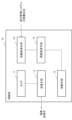
- FIG. 1 is a diagram illustrating a configuration of an embodiment of the present disclosure. 4 is a flow diagram illustrating the operation of one embodiment of the present disclosure.
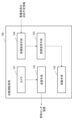
- FIG. 2 is another diagram showing a configuration of an embodiment of the present disclosure.
- FIG. 1 is a block diagram showing a configuration of an autonomous driving vehicle according to a first embodiment of the present disclosure. 1 is a flow chart illustrating the operation of an autonomous vehicle according to a first embodiment of the present disclosure.
- FIG. 2 is a diagram for explaining the route changing operation of an autonomous driving vehicle according to the first embodiment of the present disclosure.
- FIG. 2 is another diagram for explaining the route changing operation of the autonomous driving vehicle of the first embodiment of the present disclosure.
- FIG. 11 is a block diagram showing the configuration of an autonomous driving vehicle according to a second embodiment of the present disclosure.
- FIG. 11 is a diagram for explaining the route changing operation of an autonomous driving vehicle according to the second embodiment of the present disclosure.
- FIG. 13 is a block diagram showing a configuration of a control center device according to a third embodiment of the present disclosure. 13 is a flowchart showing the operation of a control center device according to a third embodiment of the present disclosure.
- FIG. 13 is a diagram for explaining a route change operation of a moving object according to a fourth embodiment of the present disclosure.
- FIG. 13 is a diagram for explaining a further modified embodiment of the fourth embodiment of the present disclosure.
- FIG. 1 is a diagram showing the configuration of a computer that can function as a mobile body or control center device of the present disclosure.
- connection lines between blocks in the drawings and the like referred to in the following description include both bidirectional and unidirectional.
- One-way arrows are used to show the main flow of signals (data) and do not exclude bidirectionality.
- the program is executed via a computer device, which includes, for example, a processor, a storage device, an input device, a communication interface, and a display device as necessary.
- the computer device is configured to be able to communicate with devices (including computers) inside or outside the device via the communication interface, whether wired or wireless.
- ports or interfaces are provided at the connection points for input and output of each block in the drawings, but are not shown.
- the present disclosure can be realized in a mobile object 10 equipped with a camera 11, a moving means 12, a transmitting means 13, an information acquiring means 14, and a route changing means 15, as shown in FIG. 1.
- the moving means 12 is composed of various propulsion devices that function as moving means for moving objects along a preset route, and a control device that controls these.
- the transmission means 13 transmits the images captured by the camera 11 to a specified destination.
- the camera 11, the moving means 12, and the transmission means 13 can be those equipped in an unmanned aerial vehicle (UAV) known as a drone or an autonomous vehicle.
- UAV unmanned aerial vehicle
- the information acquisition means 14 acquires information indicating the operation status of other monitoring systems.
- Information indicating the operation status of other monitoring systems includes, but is not limited to, the patrol routes and patrol schedules of security vehicles that make up the security system.
- the operation status of a surveillance camera system may be acquired as the operation status of other monitoring systems.
- Information indicating the operation status of other monitoring systems can be acquired from other monitoring systems, etc., deployed on a cloud computing platform via a wireless network.
- the route change means 15 changes the route of the mobile unit 10 based on the operation status of the other monitoring system.
- FIG. 2 shows a route change method.
- the mobile body 10 configured as described above acquires information indicating the operation status of other monitoring systems (step S01), and changes the route of the mobile body 10 based on the operation status of the other monitoring systems (step S02).
- the mobile body 10 changes the route to one that complements the monitoring capabilities of the other monitoring systems, based on the operating status of the other monitoring systems. For example, when the other monitoring systems are in a paused state, the mobile body 10 performs an operation to include the monitoring area of the other monitoring systems in the route, and transmits the captured images to a specified destination. For example, when the other monitoring systems have sufficient monitoring capabilities, the mobile body 10 performs an operation to remove the monitoring area of the other monitoring systems from the route. This allows the mobile body 10 to focus on patrolling and photographing locations that cannot be monitored by the other monitoring systems.
- the mobile body 10 that operates as described above makes it possible to build a remote monitoring system that can change the monitoring area in cooperation with other monitoring systems.
- the mobile object 10 is provided with the information acquisition means 14 and the route change means 15, but these functions may be located on the mobile object control device that controls the route of the mobile object.
- Figure 3 is another diagram showing the configuration of one embodiment of the present disclosure.
- a mobile object control device 20 that includes a setting means 23, an information acquisition means 24, and a route change means 25.
- the setting means 23 sets the route of a mobile object for transmitting an image captured by a camera to a specified destination.
- the information acquisition means 24 acquires information indicating the operation status of the other monitoring systems. Then, the route change means 25 changes the route set for the mobile body based on the operation status of the other monitoring systems.
- the mobile object control device 20 configured as described above acquires information indicating the operation status of other monitoring systems (step S01), and changes the route of the mobile object 10 based on the operation status of the other monitoring systems (step S02).
- the mobile control device 20 that operates as described above also makes it possible to build a remote monitoring system that can change the monitoring area in cooperation with other monitoring systems.
- the other monitoring system described above may be a monitoring system that performs monitoring using a second moving body with a person on board.
- the route changing means 15, 25 of each of the above-mentioned forms it is preferable for the route changing means 15, 25 of each of the above-mentioned forms to perform an operation to change the route to a second route that patrols locations that cannot be monitored by the second moving body, based on the route of the second moving body acquired from the information acquisition means 14, 24.
- the moving body 10 it is possible for the moving body 10 to perform monitoring that covers locations that are likely to be insufficiently monitored by other monitoring systems.
- FIG. 4 is a block diagram showing the configuration of an autonomous vehicle 100 according to the first embodiment of the present disclosure.
- an autonomous vehicle 100 that includes a camera 101, a moving means 102, a transmitting means 103, an information acquiring means 104, and a route changing means 105.
- the moving means 102 is a means for moving the autonomous vehicle 100 along a preset route, and specifically, is composed of multiple wheels, motors that drive the wheels, a control device, etc.
- the transmission means 103 transmits the images captured by the camera 101 to the control center device.
- the information acquisition means 104 acquires security vehicle patrol schedule information from an external terminal or the like that manages the security vehicles.
- the security vehicle patrol schedule information includes the security vehicle's patrol route and patrol schedule.
- security vehicles may include various vehicles that perform surveillance tasks, such as security company vehicles and inspection vehicles, in addition to police vehicles.
- the route change means 105 creates a route that complements the surveillance area of the security vehicle based on the patrol schedule information status of the security vehicle, and sets it in the transportation means 102.
- FIG. 5 is a flow diagram showing the operation of the autonomous vehicle 100 of the first embodiment of the present disclosure.
- the autonomous vehicle 100 acquires patrol schedule information for security vehicles from an external terminal or the like that manages the security vehicles (step S001).
- the autonomous vehicle 100 creates a route that complements the surveillance area of the security vehicle based on the patrol schedule information of the security vehicle (step S002).
- the route can also be created by the route change means 105 creating a route that patrols specific points determined from the patrol schedule information of the security vehicle each time.
- the route change means 105 can select a route that meets the conditions from multiple routes created in advance.
- the autonomous vehicle 100 sets the created route in the transportation means 102 and changes the route after the change (step S003).
- FIG. 6 is a diagram for explaining the route change operation of the autonomous vehicle 100 disclosed herein.
- the diagram on the left side of FIG. 6 shows the patrol route R1 of the autonomous vehicle 100 when the security vehicle is not patrolling as a result of acquiring the patrol schedule information of the security vehicle.
- the autonomous vehicle 100 creates and moves along a figure-8 shaped patrol route R1 that covers the entire area shown in the figure in order to monitor the entire area.
- the diagram on the right of Figure 6 shows the patrol route of the autonomous vehicle 100 when a security vehicle is patrolling.
- the autonomous vehicle 100 creates and moves along a cross-shaped patrol route R2 that covers the sections not patrolled by security vehicles, shown by dotted lines.
- the autonomous vehicle 100 can switch patrol routes taking into account the operating status of the security vehicles, making it possible to efficiently monitor the area shown in Figure 6.
- FIG. 7 is another diagram for explaining the route change operation of the autonomous vehicle 100 of the present disclosure.
- the diagram on the left side of FIG. 7 shows the patrol route R1a of the autonomous vehicle 100 when the security vehicle is not patrolling as a result of acquiring the patrol schedule information of the security vehicle.
- the autonomous vehicle 100 creates a patrol route R1a that goes clockwise around the perimeter of the specified area and moves along it.
- the diagram on the right of Figure 7 shows the patrol route of the autonomous vehicle 100 when a security vehicle is patrolling.
- the autonomous vehicle 100 creates a patrol route R2a that travels along the same route as the security vehicle, shown by the dotted line, in the opposite direction, and travels along that route.
- R2a that travels along the same route as the security vehicle, shown by the dotted line, in the opposite direction, and travels along that route.
- the autonomous vehicle 100 is described as switching between two patrol routes R1, R2 or R1a, R2a, but the manner in which the autonomous vehicle 100 switches between patrol routes is not limited to the examples of Figures 6 and 7. For example, if there are multiple patterns for the patrol route of a security vehicle, the autonomous vehicle 100 may move along a patrol route that corresponds to these different patrol routes.
- the frequency with which the autonomous vehicle 100 obtains security vehicle patrol schedule information may be every few hours, but by obtaining the information more frequently, the autonomous vehicle 100 can also respond to emergency events. For example, there may be cases in which a security vehicle discovers an incident or accident while on patrol and must stop patrol. In such a case, by having the autonomous vehicle 100 obtain security vehicle patrol schedule information, it may be possible to switch from patrol route R2 on the right side of Figure 6 to patrol route R1 on the left side of Figure 6, and have the autonomous vehicle 100 patrol in place of the security vehicle.
- the patrol route may be created taking into consideration traffic rules that apply to security vehicles. For example, a security vehicle cannot patrol pedestrian-only areas where vehicles are prohibited from entering. In this case, an autonomous vehicle 100 that can travel on sidewalks may be used to create a route that strengthens monitoring of the pedestrian-only area. For example, a security vehicle cannot patrol a one-way road in the opposite direction. In this case, the autonomous vehicle 100, which is not subject to traffic rules for vehicles, may be configured to create a route that travels in the opposite direction on a one-way road. In this way, it becomes possible to identify people and vehicles in pedestrian-only areas and one-way roads that are not monitored by security vehicles.
- FIG. 8 is a block diagram showing the configuration of an autonomous vehicle 100a according to the second embodiment of the present disclosure.
- the difference from the first embodiment shown in FIG. 4 is that a route change function that takes into account the time period and day of the week is added to the route change means 105a of the autonomous vehicle 100a. Since the other configurations and operations are the same as those of the first embodiment, the description will be omitted and the differences will be mainly described.
- the route change means 105a in this embodiment holds multiple patterns of routes, selects one from these routes depending on the time of day and day of the week, and sets it in the transportation means 102.
- FIG. 9 is a diagram for explaining the route change operation of a moving body in the second embodiment of the present disclosure.
- the diagram on the left of FIG. 9 shows the patrol route R1 of the autonomous vehicle 100a when no security vehicles are patrolling, and is the same as that shown on the left of FIG. 6. Meanwhile, the two diagrams on the top and bottom of the right side of FIG. 9 show the patrol routes that the autonomous vehicle 100a uses depending on the time of day and the day of the week when security vehicles are patrolling.
- the autonomous vehicle 100a selects the patrol route in the upper right of FIG. 9 from the patrol routes shown on the right side of FIG. 9 and moves along that route. Furthermore, if the current time is in the morning or evening on a weekday, the autonomous vehicle 100a selects the patrol route R3 in the lower right of FIG. 9 from the patrol routes shown on the right side of FIG. 9 and moves along that route. In this way, the autonomous vehicle 100a can be made to watch over children going to and from school. In particular, in the patrol route R3 in FIG. 9, the autonomous vehicle 100a is set to move in the opposite direction to the security vehicle. In this way, it is possible for the security vehicle and the autonomous vehicle 100a to monitor children and people entering and leaving the school by passing each other.
- autonomous vehicle 100a selects patrol route R1 when no security vehicles are patrolling, but autonomous vehicle 100a may select a patrol route from among multiple routes according to the current time or day of the week even when no security vehicles are patrolling.
- the route change means 105a has multiple route patterns stored, and from these routes, a tour route is selected according to the time of day and the day of the week.
- the route change means 105a may create a tour route each time.
- the route change means 105a switches the tour route by changing the rules for creating the tour route according to the time of day and the day of the week.
- the patrol route was switched from the viewpoint of photographing children and people entering and leaving the school, but the patrol route may also be changed from other viewpoints. For example, if there is an area where incidents and accidents occur frequently, the patrol route may be set to strengthen patrols at times when incidents and accidents are more likely. Also, for example, if there is an area where there is a lot of pedestrian traffic, the patrol route may be set to strengthen patrols at times when there is a lot of pedestrian traffic.
- a control center device (corresponding to a mobile control device) that controls the route of an autonomous vehicle 100b has a function for changing a patrol route based on the operation status of security vehicles
- Fig. 10 is a block diagram showing the configuration of the control center device of the third embodiment of the present disclosure.
- a control center device 200 including a receiving means 202, a setting means 203, an information acquisition means 204, and a route change means 205.
- the receiving means 202 receives captured images from the autonomous vehicle 100b, and sends the received captured images to the image display device 300.
- the control center personnel also refer to the information displayed on the image display device 300 to perform control operations.
- the setting means 203 sets a route for the autonomous vehicle 100b.
- the information acquisition means 204 acquires security vehicle patrol schedule information from an external terminal or the like that manages the security vehicles.
- the route change means 205 creates a route that complements the surveillance area of the security vehicle based on the patrol schedule information of the security vehicle, and instructs the setting means 203 to set a route to the autonomous vehicle 100b.
- FIG. 11 is a flow chart showing the operation of the control center device 200 of the third embodiment of the present disclosure.
- the control center device 200 acquires patrol schedule information for security vehicles from an external terminal or the like that manages the security vehicles (step S101).
- the control center device 200 creates a patrol route that complements the surveillance area of the security vehicle based on the patrol schedule information of the security vehicle (step S202).
- the patrol route can be created by the route change means 205 creating a route that patrols specific points each time, but it can also be created by selecting a patrol route that meets the conditions from multiple routes created in advance.
- control center device 200 instructs the setting means 203 to set the created patrol route and instructs movement along the changed route (step S203).
- the moving body is an autonomous vehicle, but the moving body to which the present disclosure can be applied is not limited to an autonomous vehicle.
- the present disclosure can be applied to a transport device or a robot that travels along a route in a specified area. In this case, these devices change their route based on the operation status of other monitoring systems, as shown in the robot 100c in FIG. 12.
- the present disclosure can be applied to a drone that flies along a route in a specified area. In this case, these devices change their route based on the operation status of other monitoring systems, as shown in the drone 100d in FIG. 13.
- each component of each device represents a functional block.
- a part or all of each component of each device is realized by an arbitrary combination of an information processing device 900 and a program as shown in Fig. 14, for example.
- Fig. 14 is a block diagram showing an example of a hardware configuration of the information processing device 900 that realizes each component of each device.
- the information processing device 900 includes, as an example, the following configuration.
- each device in each embodiment are realized by the CPU 901 acquiring and executing a program 904 that realizes these functions. That is, the CPU 901 in FIG. 14 executes a program that acquires information indicating the operation status of other monitoring systems and a program that changes the path based on the operation status of the other monitoring systems, and performs an update process for each calculation parameter stored in the RAM 903, storage device 905, etc.
- the program 904 that realizes the function of each component of each device is, for example, stored in advance in the storage device 905 or ROM 902, and is read by the CPU 901 as necessary.
- the program 904 may be supplied to the CPU 901 via the communication network 909, or may be stored in advance in the recording medium 906, and the drive device 907 may read the program and supply it to the CPU 901.
- this program 904 can display the processing results, including intermediate states, at each stage as necessary via a display device, or can communicate with the outside via a communication interface. Furthermore, this program 904 can be recorded on a computer-readable (non-transitive) storage medium.
- each device may be realized by any combination of a separate information processing device 900 and a program for each component.
- the multiple components of each device may be realized by any combination of a single information processing device 900 and a program.
- it can be realized by a computer program that causes the processors installed in these devices shown in the first to fifth embodiments described above to execute each of the above-mentioned processes using their hardware.
- each device is realized by other general-purpose or dedicated circuits, processors, etc., or a combination of these. These may be configured by a single chip, or may be configured by multiple chips connected via a bus.
- each device may be realized by a combination of the above-mentioned circuits and programs.
- the multiple information processing devices, circuits, etc. may be centrally located or distributed.
- the information processing devices, circuits, etc. may be realized as a client-server system, cloud computing system, etc., in a form in which each is connected via a communication network.
- first to third embodiments described above can be combined to form another embodiment.
- [Appendix 1] A camera and A means of transportation that moves along a preset route; a transmitting means for transmitting an image captured by the camera to a predetermined destination; An information acquisition means for acquiring information indicating the operating status of another monitoring system; A route change means for changing the route based on the operation status of the other monitoring system; A moving body comprising: [Appendix 2]
- the route change means of the above-mentioned mobile body may be configured to select a route from a plurality of pre-set routes based on a time period or a day of the week.
- the other monitoring system described above is a monitoring system that performs monitoring using a second moving object on which a person is riding
- the route changing means of the above-mentioned moving body can be configured to change the route to a second route that patrols areas that cannot be monitored by the second moving body, based on the route of the second moving body acquired from the information acquisition means.
- the above-mentioned mobile body may be configured to set, as the second route, a route for monitoring a pedestrian-only area or a route for moving in the reverse direction on a one-way street.
- a mobile control device comprising: [Appendix 6]
- the route change means of the above-mentioned mobile body control device may be configured to select a route based on a time period or a day of the week from a plurality of routes set in advance.
- the other monitoring system described above is a monitoring system that performs monitoring using a second moving object on which a person is riding
- the route changing means of the above-mentioned mobile body control device can be configured to change the route to a second route that patrols locations that cannot be monitored by the second mobile body, based on the route of the second mobile body acquired from the information acquisition means.
- the above-mentioned mobile object control device can be configured to set, as the second route, a route for monitoring a pedestrian-only area or a route for moving in the reverse or forward direction on a one-way street.
- [Appendix 9] a mobile object that is equipped with a camera, moves along a preset route, and transmits images captured by the camera to a predetermined destination; Obtain information showing the operation status of other monitoring systems, changing the route based on the operation status of the other monitoring system; How to change the route.
- a mobile object control device that includes a camera and receives an image captured by the camera from a mobile object moving along a preset route, Obtain information showing the operation status of other monitoring systems, changing a route set for the moving body based on an operation status of the other monitoring system; setting the route for the moving object; How to change the route.
- Appendix 11 A computer mounted on a mobile object that has a camera, moves along a preset route, and transmits images captured by the camera to a predetermined destination, A process of acquiring information indicating the operation status of another monitoring system; A process of changing the route based on an operation status of the other monitoring system; A recording medium on which a program for executing the above is recorded.
- [Appendix 12] A computer mounted on a mobile object control device that is equipped with a camera and receives images captured by the camera from a mobile object moving along a preset route, A process of acquiring information indicating the operation status of another monitoring system; A process of changing a route set for the moving object based on an operation status of the other monitoring system; A recording medium on which a program for executing the above is recorded.
- the forms of Supplementary Notes 9 to 12 can be expanded into the forms of Supplementary Notes 2 to 4, similarly to Supplementary Note 1.
- any numerical value or small range included within the range should be interpreted as being specifically described even if not otherwise specified.
- the disclosures of the above cited documents may be used in part or in whole in combination with the disclosures of this document as part of the disclosure of this document in accordance with the spirit of this disclosure, as necessary, and are deemed to be included in the disclosures of this application.
Landscapes
- Engineering & Computer Science (AREA)
- Radar, Positioning & Navigation (AREA)
- Remote Sensing (AREA)
- Automation & Control Theory (AREA)
- Physics & Mathematics (AREA)
- General Physics & Mathematics (AREA)
- Multimedia (AREA)
- Signal Processing (AREA)
- Traffic Control Systems (AREA)
Abstract
Description
続いて、自律的に移動し、管制センタ装置に画像を送信する自動運転車両に、他の監視システムの稼働状況に基づいた協調動作機能を追加した第1の実施形態について図面を参照して詳細に説明する。以下の説明では、他の監視システムとして、警備車両の巡回予定情報を用いるものとして説明する。図4は、本開示の第1の実施形態の自動運転車両100の構成を表したブロック図である。
続いて、自動運転車両100に、時間帯や曜日を考慮した経路の変更機能を追加した第2の実施形態について図面を参照して詳細に説明する。図8は、本開示の第2の実施形態の自動運転車両100aの構成を表したブロック図である。図4に示した第1の実施形態との相違点は、自動運転車両100aの経路変更手段105aに時間帯や曜日を考慮した経路の変更機能が追加されている点である。その他の構成及び動作は第1の実施形態と同様であるため、説明を省略し、その相違点を中心に説明する。
続いて、自動運転車両100bの経路の制御を行う管制センタ装置(移動体制御装置に相当)に、警備車両の稼働状況に基づいた巡回経路の変更機能を配置した第3の実施形態について図面を参照して詳細に説明する。図10は、本開示の第3の実施形態の管制センタ装置の構成を表したブロック図である。
上記した第1~第3の実施形態では、移動体が自動運転車両である例を挙げて説明したが、本開示を適用可能な移動体は自動運転車両に限定されない。例えば、指定されたエリアを経路に沿って走行する搬送装置やロボット等に本開示を適用することもできる。この場合、これらの装置は、図12のロボット100cに示すように、他の監視システムの稼働状況に基づいて、経路を変更することになる。また例えば、指定されたエリアを経路に沿って飛行するドローン等に本開示を適用することもできる。この場合、これらの装置は、図13のドローン100dに示すように、他の監視システムの稼働状況に基づいて、経路を変更することになる。
本開示の各実施形態において、各装置の各構成要素は、機能単位のブロックを示している。各装置の各構成要素の一部又は全部は、例えば図14に示すような情報処理装置900とプログラムとの任意の組み合わせにより実現される。図14は、各装置の各構成要素を実現する情報処理装置900のハードウェア構成の一例を示すブロック図である。情報処理装置900は、一例として、以下のような構成を含む。
・CPU(Central Processing Unit)901
・ROM(Read Only Memory)902
・RAM(Random Access Memory)903
・RAM903にロードされるプログラム904
・プログラム904を格納する記憶装置905
・記録媒体906の読み書きを行うドライブ装置907
・通信ネットワーク909と接続する通信インターフェース908
・データの入出力を行う入出力インターフェース910
・各構成要素を接続するバス911
カメラと、
予め設定された経路に沿って移動する移動手段と、
所定の送信先に対し、前記カメラで撮影した画像を送信する送信手段と、
他の監視システムの稼働状況を示す情報を取得する情報取得手段と、
前記他の監視システムの稼働状況に基づいて、前記経路を変更する経路変更手段と、
を備える移動体。
[付記2]
上記した移動体の前記経路変更手段は、事前に設定された複数の経路の中から、時間帯又は曜日に基づいて経路を選択する構成を採ることができる。
[付記3]
上記した他の監視システムは、人が搭乗した第2の移動体による監視を行う監視システムであり、
上記した移動体の前記経路変更手段は、前記情報取得手段から取得した、前記第2の移動体の経路に基づいて、前記第2の移動体で監視できない箇所を巡回する第2の経路に変更する構成を採ることができる。
[付記4]
上記した移動体は、前記第2の経路として、歩行者専用エリアを監視する経路又は一方通行路を逆方向に移動する経路を設定する構成を採ることができる。
[付記5]
カメラで撮影した画像を所定の送信先に送信する移動体に対して、前記移動体の経路を設定する設定手段と、
他の監視システムの稼働状況を示す情報を取得する情報取得手段と、
前記他の監視システムの稼働状況に基づいて、前記移動体に設定した経路を変更する経路変更手段と、
を備える移動体制御装置。
[付記6]
上記した移動体制御装置の前記経路変更手段は、事前に設定された複数の経路の中から、時間帯又は曜日に基づいた経路を選択する構成を採ることができる。
[付記7]
上記した他の監視システムは、人が搭乗した第2の移動体による監視を行う監視システムであり、
上記した移動体制御装置の前記経路変更手段は、前記情報取得手段から取得した、前記第2の移動体の経路に基づいて、前記第2の移動体で監視できない箇所を巡回する第2の経路に変更する構成を採ることができる。
[付記8]
上記した移動体制御装置は、前記第2の経路として、歩行者専用エリアを監視する経路又は一方通行路を逆方向又は順方向に移動する経路を設定する構成を採ることができる。
[付記9]
カメラを備え、予め設定された経路に沿って移動し、所定の送信先に対し、前記カメラで撮影した画像を送信する移動体が、
他の監視システムの稼働状況を示す情報を取得し、
前記他の監視システムの稼働状況に基づいて、前記経路を変更する、
経路変更方法。
[付記10]
カメラを備え、予め設定された経路に沿って移動する移動体から、前記カメラで撮影した画像を受信する移動体制御装置が、
他の監視システムの稼働状況を示す情報を取得し、
前記他の監視システムの稼働状況に基づいて、前記移動体に設定した経路を変更し、
前記移動体に対して、前記経路を設定する、
経路変更方法。
[付記11]
カメラを備え、予め設定された経路に沿って移動し、所定の送信先に対し、前記カメラで撮影した画像を送信する移動体に搭載されたコンピュータに、
他の監視システムの稼働状況を示す情報を取得する処理と、
前記他の監視システムの稼働状況に基づいて、前記経路を変更する処理と、
を実行させるプログラムを記録した記録媒体。
[付記12]
カメラを備え、予め設定された経路に沿って移動する移動体から、前記カメラで撮影した画像を受信する移動体制御装置に搭載されたコンピュータに、
他の監視システムの稼働状況を示す情報を取得する処理と、
前記他の監視システムの稼働状況に基づいて、前記移動体に設定した経路を変更する処理と、
を実行させるプログラムを記録した記録媒体。
なお、上記付記9~付記12の形態は、付記1と同様に、付記2~付記4の形態に展開することが可能である。
11、101 カメラ
12、102 移動手段
13、103 送信手段
14、104 情報取得手段
15、105 経路変更手段
20 移動体制御装置
23、203 設定手段
24、204 情報取得手段
25、205 経路変更手段
100、100a、100b 自動運転車両
100c ロボット
100d ドローン
101 カメラ
102 移動手段
103 送信手段
104 情報取得手段
105、105a 経路変更手段
202 受信手段
900 情報処理装置
901 CPU(Central Processing Unit)
902 ROM(Read Only Memory)
903 RAM(Random Access Memory)
904 プログラム
905 記憶装置
906 記録媒体
907 ドライブ装置
908 通信インターフェース
909 通信ネットワーク
910 入出力インターフェース
911 バス
R1、R2、R1a、R2a、R3 巡回経路
Claims (14)
- カメラと、
予め設定された経路に沿って移動する移動手段と、
所定の送信先に対し、前記カメラで撮影した画像を送信する送信手段と、
他の監視システムの稼働状況を示す情報を取得する情報取得手段と、
前記他の監視システムの稼働状況に基づいて、前記経路を変更する経路変更手段と、
を備える移動体。 - 前記経路変更手段は、事前に設定された複数の経路の中から、時間帯又は曜日に基づいて経路を選択する、
請求項1の移動体。 - 前記他の監視システムは、人が搭乗した第2の移動体による監視を行う監視システムであり、
前記経路変更手段は、前記情報取得手段から取得した、前記第2の移動体の経路に基づいて、前記第2の移動体で監視できない箇所を巡回する第2の経路に変更する、
請求項1の移動体。 - 前記第2の経路として、歩行者専用エリアを監視する経路又は一方通行路を逆方向に移動する経路を設定する、
請求項3の移動体。 - 前記第2の経路として、前記第2の移動体と同一の経路を逆方向に移動する経路を設定する、
請求項3の移動体。 - カメラで撮影した画像を所定の送信先に送信する移動体に対して、前記移動体の経路を設定する設定手段と、
他の監視システムの稼働状況を示す情報を取得する情報取得手段と、
前記他の監視システムの稼働状況に基づいて、前記移動体に設定した経路を変更する経路変更手段と、
を備える移動体制御装置。 - 前記経路変更手段は、事前に設定された複数の経路の中から、時間帯又は曜日に基づいた経路を選択する、
請求項6の移動体制御装置。 - 前記他の監視システムは、人が搭乗した第2の移動体による監視を行う監視システムであり、
前記経路変更手段は、前記情報取得手段から取得した、前記第2の移動体の経路に基づいて、前記第2の移動体で監視できない箇所を巡回する第2の経路に変更する、
請求項6の移動体制御装置。 - 前記第2の経路として、歩行者専用エリアを監視する経路又は一方通行路を逆方向に移動する経路を設定する、
請求項8の移動体制御装置。 - 前記第2の経路として、前記第2の移動体と同一の経路を逆方向に移動する経路を設定する、
請求項8の移動体制御装置。 - カメラを備え、予め設定された経路に沿って移動し、所定の送信先に対し、前記カメラで撮影した画像を送信する移動体が、
他の監視システムの稼働状況を示す情報を取得し、
前記他の監視システムの稼働状況に基づいて、前記経路を変更する、
経路変更方法。 - カメラを備え、予め設定された経路に沿って移動する移動体から、前記カメラで撮影した画像を受信する移動体制御装置が、
他の監視システムの稼働状況を示す情報を取得し、
前記他の監視システムの稼働状況に基づいて、前記移動体に設定した経路を変更する、
経路変更方法。 - カメラを備え、予め設定された経路に沿って移動し、所定の送信先に対し、前記カメラで撮影した画像を送信する移動体に搭載されたコンピュータに、
他の監視システムの稼働状況を示す情報を取得する処理と、
前記他の監視システムの稼働状況に基づいて、前記経路を変更する処理と、
を実行させるプログラムを記録した記録媒体。 - カメラを備え、予め設定された経路に沿って移動する移動体から、前記カメラで撮影した画像を受信する移動体制御装置に搭載されたコンピュータに、
他の監視システムの稼働状況を示す情報を取得する処理と、
前記他の監視システムの稼働状況に基づいて、前記移動体に設定した経路を変更する処理と、
を実行させるプログラムを記録した記録媒体。
Priority Applications (2)
| Application Number | Priority Date | Filing Date | Title |
|---|---|---|---|
| PCT/JP2023/005972 WO2024176298A1 (ja) | 2023-02-20 | 2023-02-20 | 移動体、移動体制御装置、経路変更方法及び記録媒体 |
| JP2025501929A JPWO2024176298A5 (ja) | 2023-02-20 | 移動体、移動体制御装置、経路変更方法及びプログラム |
Applications Claiming Priority (1)
| Application Number | Priority Date | Filing Date | Title |
|---|---|---|---|
| PCT/JP2023/005972 WO2024176298A1 (ja) | 2023-02-20 | 2023-02-20 | 移動体、移動体制御装置、経路変更方法及び記録媒体 |
Publications (1)
| Publication Number | Publication Date |
|---|---|
| WO2024176298A1 true WO2024176298A1 (ja) | 2024-08-29 |
Family
ID=92500459
Family Applications (1)
| Application Number | Title | Priority Date | Filing Date |
|---|---|---|---|
| PCT/JP2023/005972 Ceased WO2024176298A1 (ja) | 2023-02-20 | 2023-02-20 | 移動体、移動体制御装置、経路変更方法及び記録媒体 |
Country Status (1)
| Country | Link |
|---|---|
| WO (1) | WO2024176298A1 (ja) |
Citations (5)
| Publication number | Priority date | Publication date | Assignee | Title |
|---|---|---|---|---|
| JPH10266575A (ja) * | 1997-03-26 | 1998-10-06 | Ohbayashi Corp | 建築用自律移動ロボット |
| JP2012078950A (ja) * | 2010-09-30 | 2012-04-19 | Sogo Keibi Hosho Co Ltd | 自律移動体を用いた監視システム、監視装置、自律移動体、監視方法、及び監視プログラム |
| JP2017062179A (ja) * | 2015-09-25 | 2017-03-30 | シャープ株式会社 | サーバ装置、移動体、及び走行経路選択方法 |
| JP2018116359A (ja) * | 2017-01-16 | 2018-07-26 | 本田技研工業株式会社 | 自律移動型ロボット運行管理システム |
| JP2019066381A (ja) * | 2017-10-03 | 2019-04-25 | 株式会社 ミックウェア | 経路生成装置、移動体、及びプログラム |
-
2023
- 2023-02-20 WO PCT/JP2023/005972 patent/WO2024176298A1/ja not_active Ceased
Patent Citations (5)
| Publication number | Priority date | Publication date | Assignee | Title |
|---|---|---|---|---|
| JPH10266575A (ja) * | 1997-03-26 | 1998-10-06 | Ohbayashi Corp | 建築用自律移動ロボット |
| JP2012078950A (ja) * | 2010-09-30 | 2012-04-19 | Sogo Keibi Hosho Co Ltd | 自律移動体を用いた監視システム、監視装置、自律移動体、監視方法、及び監視プログラム |
| JP2017062179A (ja) * | 2015-09-25 | 2017-03-30 | シャープ株式会社 | サーバ装置、移動体、及び走行経路選択方法 |
| JP2018116359A (ja) * | 2017-01-16 | 2018-07-26 | 本田技研工業株式会社 | 自律移動型ロボット運行管理システム |
| JP2019066381A (ja) * | 2017-10-03 | 2019-04-25 | 株式会社 ミックウェア | 経路生成装置、移動体、及びプログラム |
Also Published As
| Publication number | Publication date |
|---|---|
| JPWO2024176298A1 (ja) | 2024-08-29 |
Similar Documents
| Publication | Publication Date | Title |
|---|---|---|
| US10870437B2 (en) | Determination of strategy modes for autonomous vehicle operations | |
| US10872476B2 (en) | Broadcast strategy modes for autonomous vehicle operations | |
| US11874663B2 (en) | Systems and methods for computer-assisted shuttles, buses, robo-taxis, ride-sharing and on-demand vehicles with situational awareness | |
| US11079771B2 (en) | Coordinated optimization of autonomous vehicle operations | |
| US11092961B2 (en) | Strategy modes for autonomous vehicle operations | |
| US11619936B2 (en) | Method and apparatus for remotely controlling self-driving vehicle | |
| US11834069B2 (en) | Systems and methods for selecting trajectories based on interpretable semantic representations | |
| US10293818B2 (en) | Teleassistance data prioritization for self-driving vehicles | |
| KR102521012B1 (ko) | 협력적 차량 헤드라이트 지향 | |
| KR20220121824A (ko) | 협력적 차량 헤드라이트 지향 | |
| CN114514758A (zh) | 交通工具网络中的操纵协调服务 | |
| US20220083065A1 (en) | Systems and Methods for Generating Basis Paths for Autonomous Vehicle Motion Control | |
| DE102019121437A1 (de) | Modulare konfigurierbare Plattformarchitektur für CA/AD-Fahrzeuge | |
| US20180257661A1 (en) | Teleassistance data encoding for self-driving vehicles | |
| WO2023058360A1 (en) | Dynamic image compression for multiple cameras of autonomous vehicles | |
| DE102019129062A1 (de) | Systeme und verfahren zum übertragen einer steuerung eines unbemannten luftfahrzeugs | |
| US20240425083A1 (en) | Systems and Methods for Autonomous Vehicle Motion Control and Motion Path Adjustments | |
| DE112017008231T5 (de) | Koordiniertes autonomes fahren | |
| US20210110708A1 (en) | Hierarchical integrated traffic management system for managing vehicles | |
| CN117519944A (zh) | 一种基于算力感知和边缘云计算协同的无人车及其协同方法 | |
| US20220032934A1 (en) | Method, apparatus, device and system for controlling driving | |
| JP7679097B2 (ja) | 作業計画生成システム | |
| EP3665056B1 (en) | Strategy modes for autonomous vehicle operations | |
| WO2024176298A1 (ja) | 移動体、移動体制御装置、経路変更方法及び記録媒体 | |
| JP6678983B1 (ja) | 飛行体の管理サーバ及び管理システム |
Legal Events
| Date | Code | Title | Description |
|---|---|---|---|
| 121 | Ep: the epo has been informed by wipo that ep was designated in this application |
Ref document number: 23923954 Country of ref document: EP Kind code of ref document: A1 |
|
| ENP | Entry into the national phase |
Ref document number: 2025501929 Country of ref document: JP Kind code of ref document: A |
|
| WWE | Wipo information: entry into national phase |
Ref document number: 2025501929 Country of ref document: JP |
|
| NENP | Non-entry into the national phase |
Ref country code: DE |
|
| 122 | Ep: pct application non-entry in european phase |
Ref document number: 23923954 Country of ref document: EP Kind code of ref document: A1 |