WO2024176286A1 - 判定装置、判定方法及び判定プログラム - Google Patents
判定装置、判定方法及び判定プログラム Download PDFInfo
- Publication number
- WO2024176286A1 WO2024176286A1 PCT/JP2023/005942 JP2023005942W WO2024176286A1 WO 2024176286 A1 WO2024176286 A1 WO 2024176286A1 JP 2023005942 W JP2023005942 W JP 2023005942W WO 2024176286 A1 WO2024176286 A1 WO 2024176286A1
- Authority
- WO
- WIPO (PCT)
- Prior art keywords
- flow
- delay
- rate
- reference delay
- packet
- Prior art date
- Legal status (The legal status is an assumption and is not a legal conclusion. Google has not performed a legal analysis and makes no representation as to the accuracy of the status listed.)
- Ceased
Links
Images
















Classifications
-
- H—ELECTRICITY
- H04—ELECTRIC COMMUNICATION TECHNIQUE
- H04L—TRANSMISSION OF DIGITAL INFORMATION, e.g. TELEGRAPHIC COMMUNICATION
- H04L47/00—Traffic control in data switching networks
- H04L47/10—Flow control; Congestion control
- H04L47/12—Avoiding congestion; Recovering from congestion
- H04L47/127—Avoiding congestion; Recovering from congestion by using congestion prediction
Definitions
- the present invention relates to a determination device, a determination method, and a determination program.
- a transfer device includes devices with transfer functions such as switches, routers, optical transponders, and multiplexers) at the same time and are transferred to the same destination link.
- the forwarding device puts the subsequently arriving traffic packet of network A on hold. This wait time increases the forwarding delay of the traffic of network A.
- a variety of traffic flows (hereafter referred to as flows) flow through networks built for each service, and each has a different priority when forwarding.
- flows flow through networks built for each service, and each has a different priority when forwarding.
- the forwarding device forwards the high-priority packets first.
- a representative method is Call Admission Control (see, for example, Non-Patent Document 1).
- a transfer device on the route through which the flow passes issues permission to set up the new flow based on the traffic volume between the new flow and existing flows that are already accommodated, so as to prevent packet loss due to buffer overflow.
- the judgment criterion for issuing a setting permission is only a single criterion such as the probability of buffer overflow or excess link bandwidth, and it is difficult to apply when different judgment criteria are used for each flow.
- the present invention has been made in consideration of the above, and aims to provide a determination device, a determination method, and a determination program that can handle cases where different determination indicators are used for each traffic flow and can determine whether to accommodate a new flow based on multiple determination indicators.
- the determination device of the present invention is characterized by having: a prediction unit that accepts a request to accommodate a new traffic flow including a first indicator, which is the arrival rate of the traffic flow; a second indicator, which is a first reference delay that is a transfer delay reference value to be observed; and a third indicator, which is the first reference delay exceeding packet ratio; and a fourth indicator, which is the total amount of arrival rates of all traffic flows after the new traffic flow is accommodated in the transfer device; a sixth indicator, which is calculated based on the fourth indicator, for each second reference delay of each flow, which is the fifth indicator; a determination unit that determines, for each second reference delay, whether the second reference delay exceeding packet ratio set for each traffic flow exceeds the predicted value; and a management unit that permits the accommodation of the new traffic flow in the transfer device when the second reference delay exceeding packet ratio exceeds the predicted value.
- a prediction unit that accepts a request to accommodate a new traffic flow including a first indicator, which is the arrival rate of the traffic flow; a second indicator, which is
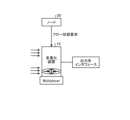
- FIG. 1 is a diagram showing a network configuration according to the first embodiment.
- FIG. 2 is a diagram showing a network configuration according to the first embodiment.
- FIG. 3 is a diagram for explaining a transfer process of the multiplexing device shown in FIG.
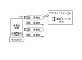
- FIG. 4 is a diagram for explaining an outline of the process of the multiplexing device shown in FIG.
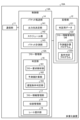
- FIG. 5 is a diagram showing an example of the configuration of the multiplexing device shown in FIG.
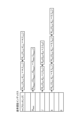
- FIG. 6 is a diagram for explaining the definition of the delay condition.
- FIG. 7 is a diagram for explaining an outline of new flow accommodation judgment.
- FIG. 8 is a diagram for explaining an outline of new flow accommodation judgment.
- FIG. 9 is a diagram for explaining the graph.
- FIG. 10 is a diagram for explaining the calculation of the reference delay.
- FIG. 10 is a diagram for explaining the calculation of the reference delay.
- FIG. 11 is a diagram for explaining the scope of application of the first embodiment.
- FIG. 12 is a diagram for explaining a request to accommodate a new flow.
- FIG. 13 is a diagram for explaining a method of calculating a delay excess packet ratio predicted value.
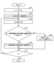
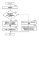
- FIG. 14 is a flowchart showing a procedure of the process executed by the multiplexing device shown in FIG.
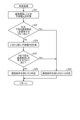
- FIG. 15 is a flowchart showing the procedure of the determination process shown in FIG.
- FIG. 16 is a diagram illustrating an example of a data configuration of the excess reference delay management table.
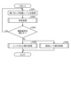
- FIG. 17 is a flowchart of the flow information removal process.
- FIG. 18 is a flowchart showing the procedure of a process for searching for a reference delay value that can be skipped.
- FIG. 19 is a diagram for explaining a method of checking whether the delay condition is met.
- FIG. 20 is a diagram showing another example of the configuration of a multiplexing device according to the second modification of the first embodiment.
- FIG. 21 is a flowchart illustrating a processing procedure according to the second modification of the first embodiment.
- FIG. 22 is a flowchart illustrating a processing procedure of another process according to the second modification of the first embodiment.
- FIG. 23 is a flowchart illustrating a processing procedure of another process according to the second modification of the first embodiment.
- FIG. 24 is a diagram for explaining the calculation process of the maximum packet rate declared value.
- FIG. 25 is a diagram illustrating an overview of a multiplexing device according to the second embodiment.
- FIG. 21 is a diagram showing another example of the configuration of a multiplexing device according to the second modification of the first embodiment.
- FIG. 21 is a flowchart illustrating a processing procedure according to the second modification of the first embodiment.
- FIG. 22 is
- FIG. 26 is a diagram for explaining an outline of a multiplexing device according to the second embodiment.
- FIG. 27 is a diagram illustrating an example of a configuration of a multiplexing device according to the second embodiment.
- FIG. 28 is a flowchart showing the procedure of the process executed by the multiplexing device shown in FIG.
- FIG. 29 is a flowchart showing the processing steps of the contract rate presentation processing shown in FIG.
- FIG. 30 is a diagram illustrating the calculation of the proposed contract flow rate.
- FIG. 31 is a diagram illustrating the calculation of the proposed contract flow rate.
- FIG. 32 is a flowchart illustrating the procedure of the rate limit execution process shown in FIG.
- FIG. 33 is a diagram for explaining the marginal utilization rate.
- FIG. 34 is a diagram for explaining the derivation of the marginal utilization rate.
- FIG. 35 is a diagram illustrating the process of determining whether or not a rate limit is to be applied.
- FIG. 36 is a diagram illustrating the process of determining whether or not a rate limit is to be applied.
- FIG. 37 is a diagram illustrating the process of removing a rate limit target.
- FIG. 38 is a diagram illustrating an example of a computer that implements a multiplexing device by executing a program.
- FIGS 1 and 2 are diagrams showing the network configuration in the first embodiment.
- LAN Local Area Network
- WAN Wide Area Network
- the transfer device outputs packets to a destination interface that cannot output packets simultaneously, adjusting the transfer timing using buffering.
- Examples of transfer devices include multiplexing devices, switches, routers, and optical transponders. Below, we will explain an example in which a multiplexing device 10 having a multiplexer is used as a transfer device.
- the multiplexing device 10 has a traffic flow (hereafter referred to as flow) management function, and transfers packets of each flow to the output destination interface according to priority.
- flow traffic flow
- the high-priority flows are all set to the same priority, multiplexed using a scheduling method that emphasizes fairness among the flows, such as round robin, and output to the forwarding path.
- the low-priority flow is forwarded after the high-priority flow is output.
- the multiplexing device 10 When the multiplexing device 10 receives a flow accommodation request from a node 20, it determines whether to accept or reject the flow accommodation request.
- the node 20 is, for example, a controller for network device management or a flow setting implementation node such as a flow sender.
- the flow accommodation request is written in an inbound signaling message sent by the controller or via a data link.
- the node 20 also sends a flow release request.
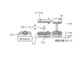
- FIG. 3 is a diagram for explaining a transfer process of the multiplexing device 10 shown in Fig. 2.
- the multiplexing device 10 multiplexes data using a multiplexer.
- the multiplexing device 10 When providing multiple real-time services on a shared network, the multiplexing device 10 multiplexes multiple service flows into one path and outputs them at a GW (gateway) of a WAN or optical network.
- the multiplexing device 10 uses optical transmission technologies such as wavelength multiplexing and time division multiplexing.
- the multiplexing device 10 treats all flows related to real-time services as high-priority flows and functions on the premise that service traffic is treated fairly. However, since the multiplexing device 10 cannot transfer multiple packets in parallel, it makes packets that arrive simultaneously wait in a queue ((1) in Figure 3). This causes packets of each flow to be delayed.
- the multiplexing device 10 maintains an environment in which the user can easily operate the device by controlling the accommodation of flows so as to observe the upper limit of the proportion of packets with excessive delays, which is set as one of the indicators.
- Figure 4 is a diagram that explains the overview of the processing of the multiplexing device 10 shown in Figure 2.
- the multiplexing device 10 restricts the flow capacity and limits the arriving traffic to suppress and optimize queuing delays ((3) in Figure 4).
- FIG. 5 is a diagram showing an example of the configuration of the multiplexing device 10 shown in Fig. 2.
- the multiplexing device 10 has a communication unit 11, a storage unit 12, and a control unit 13.
- the communication unit 11 is a communication interface that transmits packets to the destination interface.
- the communication unit 11 is realized by a NIC (Network Interface Card) or the like, and communicates between the control unit 13 (described later) and other devices via telecommunication lines such as a LAN (Local Area Network) or the Internet.
- the communication unit 11 receives a flow accommodation request or a flow release request transmitted from the node 20.
- the storage unit 12 is realized by a semiconductor memory element such as a RAM (Random Access Memory) or a flash memory, or a storage device such as a hard disk or an optical disk, and stores the processing program that operates the multiplexing device 10 and data used during the execution of the processing program.
- the storage unit 12 has data for determination 121 and a database (DB) 122 for managing flow information.
- DB database
- the judgment data 121 includes various indicators (described below) used to judge delay conditions, as well as various indicators and data used to make delay condition judgments when accommodating a flow.
- the flow information management DB 122 has a predicted value calculation program 1221 and a condition determination program 1222.
- the flow information management DB 122 may be held by an external device.
- the multiplexing device 10 has an interface for acquiring data from the flow information management DB 122.
- the predicted value calculation program 1221 is a program used to calculate the predicted value (described later) of the delay excess packet ratio, which is the sixth indicator.
- the condition determination program 1222 is a program that includes an algorithm used to determine whether or not the delay condition is satisfied.
- the control unit 13 has an internal memory for storing programs that define various processing procedures and required data, and executes various processes using these.
- the control unit 13 is an electronic circuit such as a CPU (Central Processing Unit) or an MPU (Micro Processing Unit).
- the control unit 13 has a packet forwarding unit 14 and a flow management unit 15 (determination device).
- the packet forwarding unit 14 controls the forwarding of packets of multiple flows.
- the packet forwarding unit 14 has an output destination determination unit 141, a schedule unit 142, and a packet measurement unit 143.
- the output destination determination unit 141 determines the output destination interface for packets of each flow.
- the schedule unit 142 sets the transfer order of packets of each flow according to the priority.
- the packet forwarding unit 14 forwards packets of each flow to the output destination interface determined by the output destination determination unit 141 in accordance with the transfer order set by the schedule unit 142.
- the schedule unit 142 may also have a limit function for the forwarding of packets of each flow.
- the packet measurement unit 143 measures packets of each flow and accumulates statistical information regarding the input and output of packets of each flow.
- the packet measurement unit 143 measures the arrival rate and the size and amount of arriving packets for each output interface and flow.
- the flow management unit 15 manages the flows accommodated by the multiplexing device 10.
- the flow management unit 15 has a determination unit 16 (determination device), a flow information management unit 17, and an accommodation management unit 18.
- the determination unit 16 determines whether or not the delay condition of each flow accommodated by the multiplexing device 10 is satisfied based on a number of indicators. In the first embodiment, when a new flow requested by the node 20 is accommodated, the determination unit 16 determines whether or not the delay condition is satisfied for the new flow and for flows that have already been accommodated.
- the determination unit 16 has a flow request analysis unit 161, a predicted value calculation unit 162, and a delay condition determination unit 163.
- the flow request analysis unit 161 When the flow request analysis unit 161 receives a request to accommodate a flow, it analyzes the request to accommodate this flow. From the flow accommodation request, the flow request analysis unit 161 obtains the arrival rate (first index), the first reference delay of the new flow (second index), and the first reference delay exceeding packet ratio of the new flow (hereinafter referred to as the first reference ratio) (third index) for the new flow for which accommodation has been newly requested.
- the arrival rate first index
- the first reference delay of the new flow second index
- the first reference delay exceeding packet ratio of the new flow hereinafter referred to as the first reference ratio
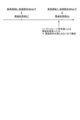
- Figure 6 is a diagram explaining the definition of the delay condition.
- the first definition of the delay condition is the transfer delay reference value that this flow should adhere to, i.e., the reference delay.
- the second definition of the delay condition is the percentage of delays that exceed the transfer delay reference value that should be adhered to, i.e., the percentage of packets exceeding the reference delay (reference percentage).
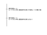
- the delay condition is that up to one in four packets have a delay of 20 msec or more.
- the delay condition is met.
- the delay condition is not met.
- the first reference delay is an index that is set using information based on the buffer capacity (e.g., the probability of blocking due to queue overflow) in order to reduce packet loss due to exceeding the buffer capacity (buffer overflow) along with delay conditions.
- the first reference delay is, for example, in units of one packet.
- the first reference rate which is the third index, is the rate of packets that experience a delay that exceeds the first reference delay of the flow, and is an index that is set based on information based on delay conditions and buffer capacity.
- the first reference rate is set for each reference delay, which is the second index. Note that in the case of a flow release request, the flow request analysis unit 161 similarly obtains the first to third indexes for the flow that is requested to be released.
- the flow request analysis unit 161 stores the first to third indicators in the judgment data 121 in association with the flow identification information.
- the flow request analysis unit 161 stores the first indicator of each flow in the judgment data 121 in association with the flow identification information.
- the total arrival rate of all flows after the new flow is accommodated in the multiplexing device 10 is set as the fourth indicator.
- the flow request analysis unit 161 stores the second indicator of each flow as the fifth indicator in association with the flow identification information in the judgment data 121.
- the flow request analysis unit 161 stores the third indicator of each flow in association with the flow identification information in the judgment data 121 as the second reference delay exceeding packet ratio (reference ratio) for each second reference delay.
- the reference ratio included in the accommodation request is referred to as the first reference ratio
- the reference ratio acquired by the flow request analysis unit 161 and stored in the determination data 121 in association with the flow identification information is referred to as the second reference ratio.
- the predicted value calculation unit 162 calculates the delay excess packet ratio predicted value (hereinafter, the predicted value) for each accommodated flow and each new flow, based on the fourth indicator and for each second reference delay of each flow, which is the fifth indicator.
- the predicted value is the sixth indicator.
- the fourth indicator is the total amount of flow packet declaration values (arrival rate) of all flows accommodated.
- the fifth indicator is the transfer delay reference value to be observed for each flow in the multiplexing device 10, i.e., the second reference delay.
- the second and fifth indicators are set based on the capacity of the buffer of the multiplexing device 10.
- the third indicator, the second reference rate, and the sixth indicator indicate the rate of packet loss due to exceeding the capacity of the buffer.
- the multiplexing device 10 also holds a second reference delay exceeding packet ratio (second reference ratio) set for each second reference delay (e.g., reference delay 1, 2, 3, ...) for each flow accommodated in the multiplexing device 10.
- the second reference ratio is set, for example, based on the delay conditions of the multiplexing device 10 and information based on the buffer capacity of the multiplexing device 10.
- the multiplexing device 10 has delay conditions with a threshold value in msec, and may calculate, for example, the allowable value for the ratio of packets exceeding the delay conditions (reference delay exceeding packet ratio) for each reference delay for each flow as the second reference ratio.
- the sixth indicator is a predicted value of the proportion of over-delay packets for each second reference delay for the corresponding flow in the multiplexing device 10.
- the predicted value is calculated based on the fourth indicator for each second reference delay, which is the fifth indicator, and is therefore an indicator based on the delay conditions of the multiplexing device 10 and information on the buffer capacity of the multiplexing device 10. The method of calculating the predicted value will be described later.
- the delay condition determination unit 163 determines whether or not the delay condition is satisfied for each accommodated flow and each new flow based on the predicted value calculated by the predicted value calculation unit 162. The delay condition determination unit 163 determines whether or not the second reference ratio exceeds the predicted value for each second reference delay for each flow.
- the delay condition determination unit 163 determines that the delay condition is satisfied if the second reference ratio exceeds the predicted value for all flows. The delay condition determination unit 163 determines that the delay condition is not satisfied if there is no flow for which the second reference ratio exceeds the predicted value.
- the flow information management unit 17 manages the flow information and manages each piece of information used to judge delay conditions. For example, the flow information management unit 17 obtains each indicator of the flow requested to be accommodated from the accommodation request, and stores it in the judgment data 121. Furthermore, the flow information management unit 17 updates the judgment data 121 if there is a change in each indicator.
- the accommodation management unit 18 accepts the flow accommodation request and permits the accommodation of the new flow to the multiplexing device 10. In other words, if the determination unit 16 determines that the second reference ratio exceeds the predicted value for both the new flow and all flows already accommodated, the accommodation management unit 18 permits the accommodation of the new flow to the multiplexing device 10.
- the accommodation management unit 18 rejects the flow accommodation request. In other words, if the determination unit 16 determines that there is a flow whose second reference ratio does not exceed the predicted value, the accommodation management unit 18 rejects the flow accommodation request.
- the accommodation management unit 18 allows the multiplexing device 10 to accommodate a new traffic flow only if all flows after accommodating the new flow satisfy the delay condition, and may also allow the multiplexing device 10 to accommodate a new flow if a predetermined number or more of flows satisfy the delay condition.
- [New flow accommodation decision] 7 and 8 are diagrams for explaining an overview of the new flow accommodation decision.
- the multiplexing device 10 decides whether or not each flow satisfies the delay condition for each flow, and determines whether or not to accommodate the new flow.
- the prediction value calculation unit 162 calculates the prediction values of the accommodated flows and new flows after newly accommodating the requested flow for each reference delay based on the queuing model (FIG. 7 (2-1)).
- the multiplexing device 10 calculates the ratio of packets exceeding the reference delay (first reference ratio) of the accommodated flow for each reference delay (in units of one packet) from the arrival packet rate (FIG. 7 (2-2)).
- the delay condition determination unit 163 compares the predicted value with the second reference ratio for each reference delay for each flow.
- the delay condition judgement unit 163 will judge that the delay condition is satisfied for the reference delay "3".
- the delay condition determination unit 163 determines that the delay condition is met.
- the accommodation management unit 18 accepts the flow accommodation request and allows the multiplexing device 10 to accommodate the new flow.
- the delay condition determination unit 163 determines that the delay condition is not satisfied. For example, for the flow being determined, if the predicted value for the reference delay "3" (box W3) is "0.6" (arrow Y2 in FIG. 8), which exceeds the reference ratio "0.5” for this reference delay "3,” the delay condition determination unit 163 determines that the delay condition is not satisfied for the reference delay "3.”
- the delay condition determination unit 163 determines that the delay condition is not satisfied.
- the accommodation management unit 18 then refuses to accommodate the new flow to the multiplexing device 10 ((4) in FIG. 7). Note that while an example has been described in which the accommodation of a new flow is refused if there is even one flow whose predicted value exceeds the second reference rate, this is not limiting.
- the accommodation management unit 18 may change the number of flows whose predicted value exceeds the second reference rate according to the accommodation capabilities of the multiplexing device 10 and then determine whether to accommodate a new flow.
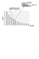
- FIG. 9 is a diagram for explaining the graphs in FIG. 7(2) and FIG. 8.
- the vertical axis of this graph indicates the predicted value (predicted value of the proportion of packets exceeding the reference delay).
- the horizontal axis indicates the reference delay.
- the right diagram in FIG. 9 indicates the proportion of packets in the queue that exist at the time of arrival when there are x packets, and the left diagram indicates the proportion of packets in the queue that exist at the time of arrival when there are x+1 or more packets.
- the excess packet ratio for a reference delay of "3" is the ratio of packets that experience a delay of 4 packets or more in the multiplexing device 10 (see the right diagram), and the value within box W2 in the left diagram is the sum of the ratios in box W3 in the right diagram.
- the reference delay is "3"
- approximately 35% of packets have a delay of 4 or more.
- Figure 10 is a diagram explaining the calculation of the reference delay.
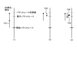
- the reference delay (time) is expressed by the following formula (1).
- the horizontal axis of the graph in Fig. 10 is the number of packets in the queue at the time of packet arrival.
- the multiplexing device 10 compares the predicted value of x1 or x2 with the reference rate of the flow according to a preset policy.
- the reference delay is the product of the packet output time and the number of packets (Equation (1)). For example, when the number of packets of "2.5" corresponds to the reference delay by converting the reference delay into the number of packets (arrow Y11 in FIG. 10), the multiplexing device 10 compares the predicted value when the number of packets is "2" or "3" with the reference ratio of the flow.
- [Scope of application] 11 is a diagram for explaining the scope of application of the first embodiment.
- the multiplexing device 10 performs a delay condition determination for each output link of the multiplexing device 10.
- the output link has a queue for high-priority traffic and a queue for low-priority traffic.
- the delay condition determination unit 163 performs the determination process on the traffic accommodated in the high-priority queue.
- the output is time-division multiplexing with a constant distribution or Ethernet approximated by an exponential distribution.
- the multiplexing device 10 calculates a predicted value in units of packet rate ⁇ and judges the delay condition of the flow.
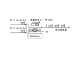
- Fig. 12 is a diagram for explaining an accommodation request for a new flow.
- the flow accommodated in the multiplexer 10 is represented by i, and the set of flows is represented as Gv .
- the multiplexing device 10 When the multiplexing device 10 receives packets of a high-priority accommodated flow i (e.g., flows 1 and 2), it queues them in a high-priority queue of the output link i and outputs them, for example, by time division multiplexing, in a transfer order determined by the scheduler 142.
- Each accommodated flow i declares a set of a flow packet rate ( arrival rate) declared value ⁇ i (first index), a first reference delay d i (second index), and a first reference ratio L i ( third index) at the time of an accommodation request R i (e.g., flows R 1 and R 2 ).
- the node 20 When a node 20 requests the multiplexing device 10 to accommodate a new flow n, the node 20 presents an accommodation request Rn for the flow to request accommodation of the new flow n. By presenting the accommodation request Rn , the packet rate declared value ⁇ n , the first reference delay dn , and the first reference rate Ln of the flow n are declared to the multiplexing device 10.
- the flow request analysis unit 161 analyzes the accommodation request Rn to obtain ⁇ n , dn , and Ln of the new flow n.
- Fig. 13 is a diagram for explaining a method for calculating the predicted value of the delay excess packet ratio (predicted value).
- the output interface of the multiplexing device 10 is time division multiplexing ( Figure 13).
- the packet arrival process of the flow is assumed to be a Poisson process. It has been reported that the process in which request-response type communication occurs can be approximated by a Poisson process. Therefore, the size of the high priority queue of the multiplexing device 10 is K, and the residence time of a packet in the multiplexing device is expressed by the M/G/1/K model.
- ⁇ j is the probability that there are j packets in the system at the boundary of a slot during time-division transmission.
- the number of packets in the system is the sum of the number of packets being transmitted and the number of packets waiting in the high-priority queue.
- a j is the probability that j packets occur within a time slot of time-division transmission.
- dB(t) in equation (3) is the density function of the probability that the packet transmission time is t.
- D max ( max[d i
- i ⁇ G v ]) is the maximum reference delay specified by a flow.
- K is the high-priority queue size, which indicates that K packets can be accommodated in the queue.
- ⁇ j (1 ⁇ j ⁇ D max ) is calculated using equation (4), where ⁇ j is the probability that there are j packets in the system at the time of the slot boundary.
- Reference 2 “Fundamentals of queuing theory 5th edition”, Willey, pp.277-278, 2018.
- Reference 3 J. Smith, “M/G/c/K blocking probability models and system performance”, Performance Evaluation, vol. 52, Issue 4, pp.
- Aj is the probability that j new packets arrive during packet forwarding.
- Aj is expressed by formula (6).
- Aj is expressed by formula (3).
- Equation (7) uses equation (7) to calculate ⁇ ′ j (1 ⁇ j ⁇ D max ) , which is the probability in M/G/1/K that a packet arriving at a multiplexer and queued without being dropped will see j packets waiting at the device upon arrival.
- pj (1 ⁇ j ⁇ Dmax ) is calculated using equation (8).
- pj is the probability that there are j packets in the multiplexing device 10 when the packets arrive at the device.
- pj corresponds to the predicted value (predicted value of the proportion of packets exceeding the reference delay), which is the sixth indicator.
- pK is calculated using equation (9).
- pK is the blocking probability due to queue overflow in M/G/1/K.
- s2 is the variance of the service time, which is 0 in the case of a constant distribution.
- Equation (10) is based on Little's rule.
- fitting statistical data using the least squares method of machine learning may be applied as a method for calculating predicted values.
- the delay for each packet is measured, and the proportion of packets for each delay is calculated.
- the parameters of an exponential function or quadratic function for calculating an approximation of the excess delay rate are estimated using statistical methods (least squares method, machine learning methods), and used to calculate an approximation of the excess delay rate.
- Fig. 14 is a flow chart showing the processing procedure executed by the multiplexing device 10 shown in Fig. 3.
- the multiplexing device 10 receives a flow accommodation request from the node 20 (step S11).
- the determination unit 16 obtains the flow packet rate declared value ⁇ n , the first reference delay d n , and the first reference rate L n from the accommodation request R n for the new flow n (step S12).
- the determination unit 16 obtains the multiplexing target interface and the high-priority queue size of the interface (step S13).
- the determination unit 16 When the determination unit 16 has accommodated the requested new flow, it performs a determination process to determine whether the new flow and the already accommodated flows satisfy the delay condition (step S14).
- step S15 if the determination unit 16 determines that the delay condition is satisfied (step S15: Yes), the accommodation management unit 18 accepts the flow accommodation request (step S16) and accommodates the new flow.
- step S15 If the determination unit 16 determines that the delay condition is not satisfied (step S15: No), the accommodation management unit 18 rejects the flow accommodation request (step S17).
- step S14 the determination process (step S14) will be described with reference to a flowchart shown in FIG.
- the decision unit 16 calculates a predicted value pj of the excess delay packet ratio for each reference delay j from the sum ⁇ of the declared packet rate values of packets after accommodating the new flow n, using calculation method 1 or calculation method 2 (step S21).
- the determination unit 16 compares the blocking probability pk based on the queue size with a first reference ratio L i for which the blocking probability pk is a required condition, and determines whether there is a flow that requires a second reference ratio L i that is lower than the blocking probability pk (step S22).
- step S22 If there is a flow that requests a first reference rate L i that is lower than the blocking probability p k (step S22: Yes), the decision unit 16 decides that the delay condition is not satisfied (step S23).
- the determination unit 16 compares the second reference ratio L i of the flow i having the reference delay j with the calculated predicted value P, and determines whether there is a flow having a first reference ratio L i that is lower than the predicted value P (step S25).
- step S25 If there is a flow having a second reference ratio L i that is lower than the predicted value P (step S25: Yes), the determination unit 16 determines that the delay condition is not satisfied (step S23). In the case of the first embodiment, if there is even one flow having a second reference ratio L i that is lower than the predicted value P, the determination unit 16 determines that the delay condition cannot be satisfied.
- step S26 If there is no flow having a first reference ratio L i that is lower than the predicted value P (step S25: No), it is determined that the delay condition is satisfied (step S26). In this case, even if the new flow n is accommodated, the determination unit 16 determines that the delay condition can be satisfied for the new flow n and all of the accommodated flows.
- the determination unit 16 performs the determination process using the excess reference delay management table shown in FIG. 16.
- FIG. 16 is a diagram showing an example of the data configuration of the excess reference delay management table.
- the flow information management unit 17 manages and updates the data.
- the multiplexing device 10 has table data that stores the values of each index used for the judgment process for each reference delay.
- the accommodation request R i,j the declared value ⁇ i,j of the flow packet rate, the first reference delay d i,j , and the first reference rate L i,j are stored.
- the subscripts i,j of each index of the request data indicate that it is a request of the jth network with the reference delay i.
- Flow information deletion process The following describes the process performed when a flow release request is received from the node 20.
- Fig. 17 is a flowchart showing the procedure of the flow information removal process.
- the multiplexing device 10 When the multiplexing device 10 receives a flow release request from a node 20 (step S31), the multiplexing device 10 obtains the arrival rate, first reference delay, and first reference ratio of the flow to be released from the flow release request. The multiplexing device 10 then deletes the flow information related to the flow requested to be released from, for example, the determination data 121 (for example, the table in FIG. 16) (step S32), and releases the accommodation of the flow requested to be released.
- the determination data 121 for example, the table in FIG. 16
- the judgment unit 16 allows the accommodation of a new flow only if the new flow and all flows already accommodated satisfy the delay condition, based on multiple indicators, namely the first to third indicators that each flow has as attributes and the fourth to sixth indicators acquired by the multiplexing device 10.
- the determination unit 16 calculates the predicted value of the excess delay packet ratio (prediction value) (sixth indicator) for each flow for each reference delay j based on the first to third indicators that each flow has as attributes, and the fourth indicator, and compares it with the second reference ratio for each flow. Then, the multiplexing device 10 allows the accommodation of a new flow if the second reference ratios for the new flow and for flows already accommodated exceed the predicted values. In contrast, the multiplexing device 10 rejects the accommodation request for a new flow if there is a flow for which the second reference ratio does not exceed the predicted value.
- prediction value prediction value
- the multiplexing device 10 therefore compares the delay conditions, which differ for each flow, with an index calculated from the traffic volume of the flows passing through the multiplexing device 10 when a new flow is accommodated, and allows the new flow to be accommodated if the delay conditions are met for all of the new flow and the flows already accommodated.
- the multiplexing device 10 is able to accommodate a new flow while taking into account the delay conditions, which differ for each flow.
- the multiplexing device 10 can handle cases where each flow has a different judgment index, and can determine whether to accommodate a new flow based on multiple judgment indexes.
- the multiplexing device 10 determines whether to accommodate the new flow based on the combination of the multiple combinations that has the strictest forwarding conditions. For example, the combination of the strictest conditions is the combination with the smallest maximum value of the bandwidth area that satisfies the conditions. This is because the bandwidth area that is actually used is often the smallest.
- the predicted value monotonically decreases as the reference delay increases. Therefore, when the judgment unit 16 checks to ensure that the predicted value does not exceed the delay condition, it checks the delay condition in order starting from the largest reference delay.
- delay conditions with different reference delay exceeding packet ratios for each reference delay.
- the minimum exceeding ratio the delay condition with the smallest reference delay exceeding packet ratio
- the condition with the smallest excess percentage is satisfied. If the minimum excess percentage of a delay condition with a smaller reference delay (for example, a delay condition with a reference delay of "7" or "8") is greater than the aforementioned minimum excess percentage, the smaller delay condition is automatically satisfied.
- the minimum excess percentage of the delay condition with the smaller reference delay is greater than the minimum excess percentage of the delay condition with the larger reference delay.
- the current bandwidth utilization meets the condition that the percentage of packets waiting in the queue for 8 packets or more is 30% or less. In this case, the percentage of packets waiting in the queue for 7 packets or more is 30% or less. Therefore, since this is below the minimum excess percentage of 40% for the delay condition of reference delay "7", the process of determining the delay condition of reference delay "7" can be skipped.
- [Search process] 18 is a flowchart showing a procedure of a process of searching for a reference delay value that can be skipped.
- a reference delay value that can be skipped is searched for, thereby shortening the determination process.
- the determination unit 16 checks whether D ⁇ minimum excess ratio at reference delay i ⁇ (step S44).
- ⁇ j in formula (4) can be written as a function of the bandwidth utilization rate, as shown in formula (15) (described later). Since the reference delay exceeding packet proportion predicted value (predicted value) is a linear function of ⁇ j , when the predicted value and the reference delay are given, the corresponding bandwidth utilization rate can be uniquely obtained. The same can be said even if the predicted value is replaced with the reference delay exceeding packet proportion of the flow.
- the delay conditions are expressed in terms of bandwidth utilization, the delay conditions are sorted in order of bandwidth utilization, and if there is a delay condition (expressed as bandwidth utilization) that is lower than the bandwidth utilization calculated from the actual traffic, it is clear that the condition cannot be met.
- Figure 19 is a diagram explaining how to check whether the delay condition is met.
- the determination unit 16 converts the delay conditions and the ratio of packets exceeding the reference delay of the flow into corresponding bandwidth utilization rates, and sorts them in ascending order of bandwidth utilization rates (upper part of Figure 19).
- the packet rate declared value is converted to a bandwidth utilization rate.
- the determination unit 16 compares the bandwidth utilization rate based on the converted declared value with the minimum bandwidth utilization rate among the bandwidth utilization rates corresponding to the delay conditions.
- the bandwidth utilization rate based on the packet rate declared value is "0.79", and there is a delay condition (reference delay "8" in Figure 19) that falls below this bandwidth utilization rate. Therefore, since it has been confirmed that the flow of this packet rate declared value does not satisfy the delay condition, the determination unit 16 rejects the accommodation request for this flow ((1) in Figure 19).
- the multiplexing device may further notify the flow that was refused accommodation of the standard delay excess packet ratio that can be accommodated (first standard ratio), and may present the flow setter via the node 20 with material for considering changing the presented packet ratio.
- the multiplexing device calculates the maximum packet rate declared value for a flow that has been refused accommodation, which satisfies the delay condition of the accommodated flow, and presents to the node 20 a packet rate declared value that is determined to be acceptable for accommodation based on the calculated maximum packet rate declared value.
- FIG. 20 is a diagram showing another example of the configuration of a multiplexing device according to the second modification of the first embodiment.
- the flow management unit 15A of the control unit 13A further includes a rate presentation unit 19.
- the rate presentation unit 19 calculates the maximum packet rate declaration value that satisfies the delay condition of the accommodated flow. Based on the calculated maximum packet rate declaration value, the rate presentation unit 19 notifies the node 20, which is the origin and/or controller of the flow that has been determined to be denied accommodation, of the packet rate declaration value that is determined to be permitted accommodation.
- the rate suggestion unit 19 searches for a rate at which the second reference ratio exceeds a predicted value for all flows after the new flow has been admitted to the multiplexing device 10, while gradually increasing or decreasing the rate from the arrival rate of the new flow declared in the admission request, and notifies the source of the admission request for the new flow (e.g., node 20) of the found rate.
- the rate presentation unit 19 also calculates the standard delay exceeding packet ratio that can be accommodated (first standard ratio) for the flow that was refused admission.
- the rate presentation unit 19 notifies the node 20, which is the origin and/or controller of the flow that was refused admission, of the standard delay exceeding packet ratio that can be accommodated (first standard ratio), and presents a consideration for changing the packet ratio.
- [Processing Procedure] 21 is a flowchart showing a processing procedure of a process according to Modification 2 of Embodiment 1. After rejecting a flow accommodation (step S51), the determination unit 16 determines whether or not a flow that does not satisfy the delay condition is a newly accommodated flow (step S52).
- the predicted value calculation unit 162 calculates the predicted value of the standard delay exceeding packet ratio (predicted value) for the standard delay of this new flow based on the total packet rate ⁇ after accommodating the new flow (step S53).
- the multiplexing device 10A presents the calculated predicted value to the node 20 as the accommodable standard delay exceeding packet ratio (first standard ratio) (step S54).
- step S52 if the flow that does not satisfy the delay condition is not a newly accommodated flow (step S52: No), the rate presentation unit 19 searches for a maximum packet rate declaration value that satisfies the delay conditions of the accommodated flows and the new flow (step S55).
- the rate presenting unit 19 presents to the node 20 the difference between the found maximum packet rate declared value and the packet rate declared value of the accommodated flow as the maximum packet rate that the multiplexing device 10A can accommodate (step S56).
- the multiplexing device 10A may present to the node 20 the maximum packet rate declared value that satisfies the delay condition of the accommodated flow, and perform the determination process of step S13 if the declared rate of the new flow satisfies the maximum packet rate declared value.
- FIGS. 22 and 23 are flowcharts showing the processing steps of other processes related to Variation 2 of Embodiment 1.
- the flow management unit 15A deletes the flow information (step S61).
- the rate presentation unit 19 calculates the maximum packet rate declaration value that satisfies the delay condition of the accommodated flow (step S62).
- the rate presentation unit 19 notifies the node 20, which is the origin and/or controller of the flow, of the maximum packet rate declaration value (step S63), and ends the process.
- the determination unit 16 determines whether the packet rate declaration value of the new flow is higher than the value calculated in step S62 (maximum packet rate declaration value) (step S64).
- step S64 If the packet rate declaration value of the new flow is higher than the value calculated in step S62 (step S64: Yes), the determination unit 16 rejects the flow accommodation request of the new flow (step S65).
- step S66 the determination unit 16 executes the same determination process as step S13 shown in FIG. 14, thereby determining whether or not to permit the accommodation request of this new flow. Note that, similar to FIG. 14, the multiplexing device 10A executes step S15 or step S16 after completing the process of step S13.
- FIG. 24 is a diagram for explaining the calculation process of the maximum packet rate declared value.
- the assumptions for the calculation of the maximum packet rate declared value are as follows. First, the rate calculation is performed discretely. Second, the adjustment unit (N) is, for example, in units of 100 Mbps or 1 G. Hereinafter, when the unit is 100 Mbps, adding 500 Mbps is described as adding 5 units.
- the rate suggestion unit 19 increases the packet rate by N units from the starting packet rate, and sets the rate that initially satisfies the delay condition as the initial value ((1) in FIG. 24).
- the starting packet rate is the rate that does not satisfy the delay condition when the rate is limited.
- the maximum packet rate is the minimum value of the contracted rate that satisfies the delay condition when the rate is limited.
- FIG. 24 (1) shows an example in which the packet rate is increased by 2N units from the starting packet rate, as indicated by the arrow Y21.
- the rate presentation unit 19 then evaluates the delay conditions when the input packet rate is a value that is N/2 units lower than the initial value, as indicated by arrow Y22 ((2) in FIG. 24). If the delay conditions are satisfied, the rate presentation unit 19 sets the value that is N/2 units lower than the initial value as the provisional value of the maximum packet rate.
- the rate display unit 19 sets the initial value as the provisional value.
- the multiplexing device 10A narrows the search width to N/4 (arrow Y23), N/8 (arrow Y24), and so on. If the rate display unit 19 can find a provisional value that does not satisfy the delay condition when reduced by even one unit, it sets that value as the maximum flow rate ((3) in FIG. 24).
- the rate presentation unit 19 also performs a similar calculation when lowering the contract rate.
- the initial value is the contract rate that does not satisfy the delay condition first when lowered by N units.
- a rate limit (limiting process) is performed to limit the output rate of the flow to the target interface to the contract rate. Also, in the second embodiment, when the traffic dynamically increases and the delay condition of the accommodated flow cannot be satisfied, a flow packet rate that can satisfy the delay condition is calculated and presented to the node 20.
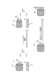
- FIG. 25 and 26 are diagrams for explaining an overview of the multiplexing device 210 (transfer device) according to the second embodiment.
- Fig. 25 and Fig. 26 for example, a case where the multiplexing device 210 activates a rate limit will be explained.
- the multiplexing device 210 stores the contract rate of the flow as an index for each flow.
- the multiplexing device 210 calculates a predicted value at the timing given a delay condition-related index from the amount of output data to the output interface of the monitored flow, and performs a determination process regarding the delay condition.
- the multiplexing device 210 monitors the traffic volume of flows that actually pass through the multiplexing device 210, and obtains the arrival rate of the flows that actually pass through the multiplexing device 210 (actual traffic arrival rate) for each output link based on the output interface and the measurement results of arriving packets for each flow, as a seventh indicator.
- the multiplexing device 210 then calculates, for each accommodated flow, a predicted value (predicted value) of the standard delay exceeding packet ratio based on the actual traffic arrival rate for each reference delay, as an eighth indicator. Based on the predicted value, the multiplexing device 210 determines whether the accommodated flow satisfies the delay condition for each flow.
- the process for determining the delay condition is the same as the process of the same name in embodiment 1.
- the multiplexing device 210 compares the second reference rate (rate of packets exceeding the reference delay) with the predicted value, which is the eighth indicator, for each second reference delay (reference delay) for each accommodated flow. If the predicted value exceeds the second reference rate for this flow ( Figure 25), the multiplexing device 210 determines that this flow does not satisfy the delay condition and that the traffic arriving at the device has increased (Figure 26 (1)). Note that in Figure 26, the thickness of the rate is used to diagrammatically indicate the magnitude of the rate.
- the multiplexing device 210 implements rate limiting ((2) in FIG. 26).
- Rate limiting is a process in which, for example, when the multiplexing device 210 accommodates flows F1 and F2, the transfer rates to the output interface for arriving packets of flows F1 and F2 are limited to the contracted rates of flows F1 and F2, respectively.
- flow F2 which had been transferred at a rate exceeding the contracted rate B2, is limited to the contracted rate B2 of flow F2.
- the multiplexing device 210 presents the user of flow F2 with rate B2', which is higher than the current contracted rate B2, as the flow rate at the time of rate limiting ((3) in FIG. 26).
- rate B2' which is higher than the current contracted rate B2
- the multiplexing device 210 negotiates with the user the packet output rate for each flow.
- the flow rate is determined by the contract with the user, and since the higher the contracted rate (bandwidth), the higher the usage fee, the more expensive it will be, the multiplexing device 210 calculates the optimal contracted rate and presents it to the user.
- FIG. 27 is a diagram showing an example of a configuration of a multiplexing device 210 according to embodiment 2.
- the multiplexing device 210 has a control unit 213 having the same functions as the control unit 13 instead of the control unit 13 shown in Fig. 10.
- the control unit 213 has a flow management unit 215 further including a rate presenting unit 219 (presenting unit), a flow information analysis unit 220 (acquisition unit), and a rate limiting unit 221 (limiting unit).
- the predicted value calculation unit 162 performs the same predicted value calculation process as in embodiment 1, regarding the flow to be processed as all flows already accommodated by the multiplexing device 210, and replacing the sum ⁇ of the packet arrival rate declaration values after accommodating the new flow with the actual traffic arrival rate ⁇ . In this way, the predicted value calculation unit 162 calculates the predicted value, which is the eighth indicator.
- Whether the delay condition is satisfied i.e., whether the predicted value, which is the eighth indicator, exceeds the second reference rate, is determined by the delay condition determination unit 163 performing the same determination process as in the first embodiment, with all flows accommodated by the multiplexing device 210 as the determination targets.
- the delay condition is expressed as a bandwidth utilization rate
- the procedure shown in FIG. 18 is not necessary, as in the first embodiment, and the flow packet rate declaration value described using FIG. 19 can be replaced with the actual traffic rate.
- the rate presentation unit 219 calculates the optimal contract rate for the flow accommodated by the multiplexing device 210, and notifies the source of the transmission rate for this flow (e.g., node 20). For example, the rate presentation unit 219 calculates the optimal contract rate for a flow that does not satisfy the delay condition.
- the rate presentation unit 219 determines whether the delay condition of the flow for which the contract rate is to be calculated is satisfied by gradually increasing or decreasing the rate from the current contract rate, and searches for a rate that satisfies the delay condition of the flow. In other words, the rate presentation unit 219 searches for a rate at which the second reference ratio exceeds the predicted value, which is the eighth index, for all traffic flows accommodated by the multiplexing device 210, while gradually increasing or decreasing the rate from the current contract rate of the flow for which the contract rate is to be searched, and notifies the source of the transmission rate of the flow for which the search is to be performed of the found rate.
- the flow information analysis unit 220 obtains the arrival rate (actual traffic arrival rate) of the flow that actually passes through the multiplexing device 210 based on the measurement results of the output interface and the amount of arriving packets for each flow by the packet measurement unit 143.
- the rate limit unit 221 executes a rate limit on all accommodated flows. Note that the rate limit may be executed when even one accommodated flow does not satisfy the delay condition, or may be executed when there are a predetermined threshold or more of accommodated flows that do not satisfy the delay condition.
- FIG. 28 is a flowchart showing the procedure of the process executed by the multiplexing device 210 shown in FIG.
- the flow information analysis unit 220 acquires the actual traffic rate ⁇ (step S201).
- the determination unit 16 calculates a predicted value (eighth index) of the delay excess packet ratio for the queuing delay value incurred by the multiplexing device 210 for each accommodated flow, and performs a determination process to determine whether each flow satisfies the delay condition (step S202).
- the process procedure for calculating the predicted value and the process for determining the delay condition are the same as the process procedure shown in FIG. 15, and it is sufficient to replace the flow packet rate declared value ⁇ i with the measured actual traffic rate ⁇ of each flow i.
- a reference value search that can be skipped may be performed as in the case shown in Fig. 18.
- the flow packet rate declared value ⁇ i may be replaced with the measured actual traffic rate ⁇ of each flow i.
- step S203 If all accommodated flows satisfy the delay condition (step S203: Yes), the multiplexing device 210 returns to the processing of step S201.
- step S203 If all of the accommodated flows do not satisfy the delay condition (step S203: No), the rate limit unit 221, for example, performs rate limit processing on all of the accommodated flows (step S204).
- the rate presenting unit 219 performs a contract rate presenting process to calculate the optimal contract rate for a flow that does not satisfy the delay condition and notify the node 20 of this flow (step S205).
- FIG. 28 is merely an example of the timing of the contract rate presentation process.
- the contract flow rate presentation process is executed periodically.
- the contract flow rate presentation process is executed when a specified event occurs.
- the rate presentation unit 219 calculates the excess delay packet ratio based on the seventh indicator, the actual traffic arrival rate, and the contract rate for the accommodated flow, and when it detects a traffic flow in which the calculated excess delay packet ratio exceeds the second reference ratio, it searches for the contract rate of the detected traffic flow.
- the flow information analysis unit 220 measures the packet arrival rate of the flow to be presented (step S211).
- the rate presentation unit 219 calculates the measured rate and the excess delay packet ratio for the flow to be presented (step S212).
- the multiplexing device 210 determines whether the delay excess packet ratio calculated in step S212 exceeds the second reference ratio for the flow to be presented (step S213).
- the rate presenting unit 219 also calculates the excess delay packet ratio for the flow to be presented when the contract rate is lowered by one unit (step S214). It then determines whether the excess delay packet ratio calculated in step S214 is lower than the second reference ratio for the flow to be presented (step S215).
- step S212 If the excess delay packet ratio calculated in step S212 does not exceed the second reference ratio of the flow to be presented (step S213: No), or if the excess delay packet ratio calculated in step S214 does not fall below the second reference ratio of the flow to be presented (step S215: No), the multiplexing device 210 returns to steps S212 and S214.
- step S212 If the delay excess packet ratio calculated in step S212 exceeds the second reference ratio of the flow to be presented (step S213: Yes), or if the delay excess packet ratio calculated in step S214 falls below the second reference ratio of the flow to be presented (step S215: Yes), the rate presenting unit 219 searches for a proposed contract rate for the flow to be presented (step S216). The rate presenting unit 219 presents the calculated proposed contract flow rate to the node 20 (step S217).
- [Calculation of proposed contract rate] 30 and 31 are diagrams for explaining the calculation of the proposed contract flow rate.
- the rate presentation unit 219 searches for the minimum contract rate that satisfies the delay condition at the rate limit as the proposed contract rate.
- the adjustment unit (N) is, for example, in units of 100 Mbps or 1 G.
- adding 100 Mbps will be described as adding 5 units.
- the rate offering unit 219 increases the contracted rate by N units, and sets the rate that first satisfies the delay condition as the initial value ( Figure 31 (1)). In this case, the current contracted rate does not satisfy the delay condition when the rate is limited.
- the final offered contracted rate is the smallest contracted rate that satisfies the delay condition when the rate is limited.
- Figure 31 (1) shows an example in which the packet rate is increased by 2N units from the starting packet rate, as indicated by arrow Y201.
- the rate presentation unit 219 then evaluates the delay conditions when the contract rate is set to a value N/2 units lower than the initial value, as indicated by arrow Y202 ((2) in FIG. 31). If the delay conditions are met, the multiplexing device 210 sets the provisional contract rate to a value N/2 units lower than the initial value.
- the rate presentation unit 219 sets the initial value as the provisional value. For the flow to be presented, the rate presentation unit 219 narrows the search width to N/4 (arrow Y203), N/8 (arrow Y204), and if it can find a provisional value that does not satisfy the delay condition when reduced by even one unit, it sets that value as the presented contract rate ((3) in Figure 31).
- the rate presentation unit 219 also performs a similar calculation when lowering the contract rate.
- the initial value is the contract rate that does not satisfy the delay condition first when lowered by N units.
- Fig. 32 is a flowchart showing the procedure of the rate limit execution process shown in Fig. 28.
- the rate limit unit 221 calculates the maximum value of the actual packet arrival rate of the multiplexing device 210 that satisfies the delay conditions (second reference delay, second reference ratio) of all flows (step S221).
- the calculation method is the same as the method shown in Figures 30 and 32.
- the flow information analysis unit 220 acquires the actual packet arrival rate at the multiplexing device 10 (step S222).
- the rate limit unit 221 determines whether the actual packet arrival rate acquired in step S222 exceeds the maximum value of the actual packet arrival rate calculated in step S221 (step S223).
- step S223 If the actual packet arrival rate exceeds the maximum actual packet arrival rate (step S223: Yes), the rate limiter 221 limits the transfer rate to the output interface for arriving packets of the flow to the contracted rate for all flows (step S224) (see (2) in FIG. 26).
- step S223 if the actual packet arrival rate does not exceed the maximum value of the actual packet arrival rate (step S223: No), the rate limit unit 221 returns to step S222.
- the multiplexing device 210 monitors the actual traffic volume and measures the actual arrival rate of the multiplexing device 210 for each output link, thereby calculating a predicted value of the ratio of packets exceeding the reference delay (predicted value) for each flow and for each reference delay.
- the multiplexing device 210 judges whether or not the accommodated flows satisfy the delay conditions of each flow based on the predicted value. If there is a flow that does not satisfy the delay conditions, the multiplexing device 210 executes, for example, a rate limit for all flows.
- the multiplexing device 210 it is possible to dynamically control the execution of the rate limit in response to changes in the actual traffic volume. For example, according to the multiplexing device 210, even if there is a sudden increase in traffic when there is a margin of transmission capacity, it is possible to provide an appropriate delay guarantee and maintain communication quality.
- the multiplexing device 210 can present the optimal rate to the flow setter for flows that do not satisfy the delay conditions, allowing them to change to an appropriate rate and facilitating flow accommodation.
- the optimal rate is presented when a specific event is detected, so the flow setter can be presented with the optimal rate in a timely manner.
- the delay conditions are protected by providing bandwidth guarantees in the order of strictest delay conditions.
- the strictness of the delay conditions is expressed as a "marginal utilization rate" and processing is performed.
- the rate limit unit 221 provides bandwidth guarantees to guarantee transfer at the contract rate in the order of strictest delay conditions, based on the value of the marginal utilization rate derived from the second reference ratio and the reference delay of the flow.
- the marginal utilization rate is the maximum bandwidth utilization rate for a flow that satisfies the flow's delay condition.
- Bandwidth utilization rate is the ratio of the output link arrival packet rate to the flow's transmission bandwidth, and is the value obtained by dividing the arrival rate by the transmission bandwidth.
- Figure 33 is a diagram explaining the limit utilization rate.
- the vertical axis of the graph shown in Figure 30 is the reference delay, and the horizontal axis is the predicted value of the excess delay packet ratio.
- the excess delay packet ratio is "0.35" when the reference delay is "3" ( Figure 33 (1)).
- the delay conditions for flow 1 are the reference delay of "3” and the excess delay packet ratio of "0.35", so the limit utilization rate is "0.85" ( Figure 33 (2)).
- the marginal utilization rate ⁇ i of a flow i is defined as the packet arrival rate ⁇ i of the flow divided by the transfer rate ⁇ i of the flow.
- the flow delay condition can be expressed in terms of ⁇ i as follows: In the case of M/D/1/K, A j (Equation (13)) allows ⁇ j to be written as a function of link utilization ⁇ (Equation (14)) from Equation (4).
- ⁇ is the mean packet transmission time, which is the slot length in the case of M/D/1.
- ⁇ j can be written as a function of ⁇ in a similar manner. Since A j (Equation (6)) and ⁇ j (Equation (4)) are equations in which ⁇ is a variable, the predicted value can also be calculated once ⁇ is determined.
- the predicted value of the ratio of packets exceeding the standard delay is a linear function of ⁇ j (see formula (10)). Therefore, when the predicted value and the standard delay are given, the corresponding ⁇ is uniquely determined. Since the same thing can be said even if the predicted value is replaced with the ratio of packets exceeding the standard delay of the flow, this relationship is utilized.
- the first and second processes are performed in advance to prepare reference utilization data.
- the value of the link utilization ⁇ is discretized.
- the link utilization ⁇ is set to 0, 0.01, 0.02, ..., 0.98, 0.99.
- the predicted value calculation unit 162 calculates the reference delay exceeding packet ratio predicted value (predicted value) for each discretized value.
- the third and fourth processes are performed.
- the new flow i is accommodated.
- the multiplexing device 210 accepts the reference delay and reference ratio of the new flow i as delay conditions.
- a predicted value for the accepted reference delay is searched for, and the link utilization rate ⁇ value that provides the maximum predicted value that does not exceed the accepted reference rate is set as the limit utilization rate ⁇ i of flow i.
- the predicted value (excess packet ratio predicted value) for a new flow when the reference delay is "3" is "0.34."
- the value of ⁇ "0.46" that provides the predicted value of the new flow "0.34" is set as the limit utilization rate of this new flow.
- the marginal utilization rate is calculated for each flow, and the bandwidth is guaranteed starting from the flow with the strictest marginal utilization rate, i.e., the flow with the lowest marginal utilization rate, thereby protecting the delay conditions.
- rate limiting is not implemented for all flows, but rather, rate limiting is implemented starting from the flow with the strictest delay condition, thereby maintaining smooth transfer processing.
- 35 and 36 are diagrams for explaining the process of determining whether a flow is subject to rate limiting.
- the rate limiting unit 221 determines whether a flow is subject to rate limiting by using the limit utilization rate ⁇ i .
- the rate limiting unit 221 performs a bandwidth guarantee to execute a rate limit so as to guarantee the transfer bandwidth of a flow that cannot satisfy the delay condition due to packets of other flows.
- packet forwarding for a guaranteed flow is performed by outputting flow packets to the link in accordance with the contracted rate for each flow ( Figure 35). Guaranteed flows are accommodated in individual queues. And, as long as guaranteed flows comply with the contracted rate, they are given priority for link output over other flow packets.
- packets for other flows are forwarded using the remaining bandwidth, excluding the contracted rate for the rate-limited flow.
- the rate limiting unit 221 classifies the flows it accommodates into rate-limited (guaranteed) flows S and other flows T ( Figure 36). When a flow belonging to other flows T satisfies the following conditions, the rate limiting unit 221 designates this flow as a rate-limited flow.
- the rate limit unit 221 determines the flow satisfying equation (15) as a new flow to be subject to rate limiting.
- the rate limiting unit 221 uses the limit utilization rate ⁇ i of the target, the total packet rate ⁇ T , and the transfer bandwidth ⁇ T of the entire flows belonging to other T to determine whether or not each of the flows belonging to other T is a flow that is subject to rate limiting. This allows the rate limiting unit 221 to appropriately select flows with strict delay conditions as flows that are subject to rate limiting.
- Rate limit release Furthermore, the rate limiter 221 may release the rate limit for each flow.
- FIG. 37 is a diagram explaining the process of removing a rate limit target.
- the rate limit unit 221 removes from the rate limit target those flows of rate limit target S that satisfy the delay condition even when controlled together with other flows belonging to T.
- the rate limit unit 221 excludes this flow i from the rate limit targets and reduces the number of flows subject to rate control from 3 to 2.
- rate limiting unit 221 determines whether or not the flow determined to be subject to rate limiting satisfies formula (15) as described above, thereby optimizing the number of flows subject to rate control.
- a flow i belonging to a rate limit target S will be described.
- a set of flows j ( ⁇ i > ⁇ j ) having a marginal utilization rate smaller than that of flow i is defined as Sstrict i .
- a set of flows k ( ⁇ i ⁇ ⁇ k ) having a marginal utilization rate larger than that of flow i is defined as Sloose i . If there are multiple flows having the same marginal utilization rate as flow i, the set of these flows is defined as Sequal i .
- the rate limiting unit 221 removes a flow i that is subject to rate limiting from the list of flows that are subject to rate limiting if the flow i satisfies the following conditions:
- the rate limit unit 221 excludes flows that satisfy formula (16) from the rate limit targets.
- the rate limit is triggered when the packet rates of all flows violate the delay conditions of any flow, and all flows are subject to rate limiting.
- the rate limit (bandwidth protection) is triggered when the delay condition for each flow is violated in the bandwidth for other T flows, and the rate limit is only applied to flows that cannot satisfy the delay condition in the transmission bandwidth for other T flows.
- the packet rate of all flows violates the delay condition of any flow, so the violated flow cannot provide the communication quality required by the application.
- a rate limit is applied to restrict the rate to the contract rate, so that communication quality can be reliably maintained.
- the rate presenting unit 219 presents the contracted rate to the user by adding a margin ⁇ i to accommodate fluctuations in the actual packet rate of the flow i, that is, ⁇ i + ⁇ i , where ⁇ i is preset.
- each process performed in the multiplexing device 10, 10A, 210 may be realized in whole or in part by a CPU and a program analyzed and executed by the CPU. Furthermore, each process performed in the multiplexing device 10 may be realized as hardware using wired logic.
- [program] 38 is a diagram showing an example of a computer in which a program is executed to realize the multiplexing device 10, 10A, 210.
- the computer 1000 has, for example, a memory 1010 and a CPU 1020.
- the computer 1000 also has a hard disk drive interface 1030, a disk drive interface 1040, a serial port interface 1050, a video adapter 1060, and a network interface 1070. These components are connected by a bus 1080.
- the memory 1010 includes a ROM 1011 and a RAM 1012.
- the ROM 1011 stores a boot program such as a BIOS (Basic Input Output System).
- BIOS Basic Input Output System
- the hard disk drive interface 1030 is connected to a hard disk drive 1090.
- the disk drive interface 1040 is connected to a disk drive 1100.
- a removable storage medium such as a magnetic disk or optical disk is inserted into the disk drive 1100.
- the serial port interface 1050 is connected to a mouse 1110 and a keyboard 1120, for example.
- the video adapter 1060 is connected to a display 1130, for example.
- the hard disk drive 1090 stores, for example, an OS 1091, an application program 1092, a program module 1093, and program data 1094. That is, the programs that define each process of the multiplexing device 10 are implemented as program modules 1093 in which code executable by the computer 1000 is written.
- the program modules 1093 are stored, for example, in the hard disk drive 1090.
- a program module 1093 for executing processes similar to the functional configuration of the multiplexing device 10 is stored in the hard disk drive 1090.
- the hard disk drive 1090 may be replaced by an SSD (Solid State Drive).
- the setting data used in the processing of the above-mentioned embodiment is stored as program data 1094, for example, in memory 1010 or hard disk drive 1090.
- the CPU 1020 reads the program module 1093 or program data 1094 stored in memory 1010 or hard disk drive 1090 into RAM 1012 as necessary and executes it.
- the program module 1093 and program data 1094 may not necessarily be stored in the hard disk drive 1090, but may be stored in a removable storage medium, for example, and read by the CPU 1020 via the disk drive 1100 or the like.
- the program module 1093 and program data 1094 may be stored in another computer connected via a network (such as a LAN (Local Area Network), WAN (Wide Area Network)).
- the program module 1093 and program data 1094 may then be read by the CPU 1020 from the other computer via the network interface 1070.
Landscapes
- Engineering & Computer Science (AREA)
- Computer Networks & Wireless Communication (AREA)
- Signal Processing (AREA)
- Data Exchanges In Wide-Area Networks (AREA)
Abstract
Description
[ネットワーク構成]
実施の形態1におけるネットワーク構成について説明する。図1及び図2は、実施の形態1におけるネットワーク構成を示す図である。図1に示すように、実施の形態1では、例えば、Multiplexerを有する多重化装置を介して、バックボーンネットワークがWAN(Wide Area Network)のLAN(Local Area Network)通信が行われる。
図3は、図2に示す多重化装置10の転送処理を説明する図である。多重化装置10は、Multiplexerを用いて、データの多重化を行う。
図5は、図2に示す多重化装置10の構成の一例を示す図である。多重化装置10は、通信部11、記憶部12及び制御部13を有する。
図7及び図8は、新規フロー収容判定の概要を説明する図である。多重化装置10は、各フローがフロー毎の遅延条件を満たしているか否か判定し、新規フローの収容の可否を行う。

参考文献1:Saeed Shafiee Sabet, et.al., “Towards the Impact of Gamers' Adaptation to Delay Variation on Gaming Quality of Experience”, QoMEX 2019, [令和5年1月20日検索],インターネット<URL:https://ieeexplore.ieee.org/stamp/stamp.jsp?tp=&arnumber=8743239>
図11は、実施の形態1の適用範囲を説明する図である。多重化装置10は、多重化装置10の出力リンクごとに遅延条件判定を実施する。
次に、多重化装置10がノード20から受ける新規フローの収容要求について説明する。図12は、新規フローの収容要求を説明する図である。

次に、第6の指標である予測値の計算方法について説明する。図13は、遅延超過パケット割合予測値(予測値)の計算方法を説明するための図である。

参考文献2:“Fundamentals of queuing theory 5th edition”, Willey, pp.277-278, 2018.
参考文献3:J. Smith, “M/G/c/K blocking probability models and system performance”, Performance Evaluation,vol.52, Issue 4, pp.237-267, 2003, [令和5年1月20日検索],インターネット<URL:https://reader.elsevier.com/reader/sd/pii/S0166531602001906?token=D8BD270F6F14FDD9710C2BB59FB0A717668B245FCFA7BC9DE0AFD25003A4437707DB7CEB7432B936E2A1EB67BD2F80EF&originRegion=us-east-1&originCreation=20221212120317>







多重化装置10が実行する処理手順について説明する。図14は、図3に示す多重化装置10が実行する処理の処理手順を示すフローチャートである。
次に、判定処理(ステップS14)について説明する。図15は、図14に示す判定処理の処理手順を示すフローチャートである。

なお、ノード20からフロー解放要求を受けた場合の処理について説明する。図17は、フロー情報除去処理の処理手順を示すフローチャートである。
このように、多重化装置10では、判定部16が、各フローが属性としてそれぞれ有する第1~第3の指標と、多重化装置10が取得した第4~第6の指標との複数の指標を基に、新規フロー及び収容済みの全てのフローが遅延条件を満たす場合にのみ、新規フローの収容を許可する。
実施の形態1の変形例1について説明する。実施の形態1では、全てのフローについて遅延条件に関する判定処理を行っていたが、実施の形態1の変形例1では、ステップS26の判定処理を行う前に、この処理をスキップできる基準遅延値を探索し、判定処理を高速化する。
図18は、スキップできる基準遅延値の探索処理の処理手順を示すフローチャートである。実施の形態1の変形例1では、スキップできる基準遅延値を探索することで、判定処理の短縮化を図る。
新規フロー収容拒否時のリカバリ方法について説明する。実施の形態1と比して、さらに、多重化装置は、収容を拒否したフローに対し、収容可能な基準遅延超過パケット割合(第1の基準割合)を通知し、ノード20を介してフロー設定者に提示パケット割合変更の検討材料を提示してもよい。
図21は、実施の形態1の変形例2に係る処理の処理手順を示すフローチャートである。フロー収容棄却後(ステップS51)、判定部16は、遅延条件を満たさないフローが新規収容フローであるか否かを判定する(ステップS52)。
次に、具体的に、最大パケットレート申告値の計算処理について説明する。図24は、最大パケットレート申告値の計算処理を説明する図である。なお、最大パケットレート申告値の計算の前提は、以下である。まず第1に、レート計算は離散的に行う。第2に、調整単位(N)は、例えば、100Mbps単位、1G単位などである。そして、以降では、100Mbps単位の時、500Mbps追加することを5単位追加、と記載する。
次に、実施の形態2について説明する。実施の形態2では、トラヒックが動的に増加して、収容するフローの遅延条件が満たせなくなった場合、フローの対象インタフェースへの出力レートを契約レートに制限するレートリミット(制限処理)を行う。また、実施の形態2では、トラヒックが動的に増加して、収容済みフローの遅延条件が満たせなくなった場合、遅延条件を満たすことができるフローパケットレートを計算して、ノード20に提示する。
図25及び図26は、実施の形態2に係る多重化装置210(転送装置)の概要を説明する図である。図25及び図26では、例えば、多重化装置210がレートリミットを発動する場合を例に説明する。多重化装置210は、指標として、フローの契約レートをフローごとに記憶する。
図27は、実施の形態2に係る多重化装置210の構成の一例を示す図である。図27に示すように、多重化装置210は、図10に示す制御部13に代えて、制御部13と同様の機能を有する制御部213を有する。制御部213は、制御部13と比して、フロー管理部215が、さらに、レート提示部219(提示部)、フロー情報解析部220(取得部)、及び、レートリミット部221(制限部)を有する。
図28は、図27に示す多重化装置210が実行する処理の処理手順を示すフローチャートである。
契約レート提示処理について説明する。図29は、図28に示す契約レート提示処理の処理手順を示すフローチャートである。
図30及び図31は、提示用契約フローレートの計算を説明する図である。レート提示部219は、現行契約レート(図30参照)が、レートリミット時に遅延条件を満たせない場合に、提示契約レートとして、レートリミット時に遅延条件を満たす契約レートの最小値を検索する。
多重化装置210は、以降に示すステップを、多重化装置210の出力リンクごとに実施する。図32は、図28に示すレートリミット実行処理の処理手順を示すフローチャートである。
実施の形態2に係る多重化装置210は、実トラヒック量を監視し、多重化装置210の実到着レートを出力リンクごとに計測することで、各フローについて、基準遅延ごとに、基準遅延超過パケット割合予測値(予測値)を計算する。多重化装置210は、予測値を基に、収容済みフローが、各フローの遅延条件を満たすか否かを判定する。そして、多重化装置210は、遅延条件を満たさないフローがある場合には、例えば、全フローに対してレートリミットを実行する。
実施の形態2の変形例では、遅延条件の厳しいフローから順に帯域保証を行うことで、遅延条件を保護する。実施の形態2の変形例1では、遅延条件の厳しさを「限界利用率」と表現し、処理を行う。レートリミット部221は、フローの第2の基準割合と基準遅延とから導出される限界利用率の値を基に、遅延条件が厳しいフローから順に、契約レートでの転送を保証する帯域保証を行う。
次に、フローの遅延条件と限界利用率との関係について説明する。パケット転送時間が一定分布(タイムスロットが固定長)であり、指数分布(パケットサイズが指数分布で決まる)である場合、フロー遅延条件(基準遅延、基準遅延超過パケット割合)はフローの限界利用率ρと対応する。



また、レートリミット部221は、レートリミットをフローごとに解除してもよい。

レートリミット対象のフロー数に違いがある場合、実施の形態2の手法より、実施の形態2の変形例1の手法の方が、レートリミット対象のフロー数が少ないため、多重化装置210のフロー制御負荷が低くなる。
[レート提示方法の他の例]
フローiの実測レートがλi、限界利用率がρiであるとき、レートリミット時に遅延条件を守ることができる契約レートμiは、式(17)である。

図5,20,27に示す多重化装置10,10A,210の各構成要素は機能概念的なものであり、必ずしも物理的に図示のように構成されていることを要しない。すなわち、多重化装置10,10A,210の機能の分散及び統合の具体的形態は図示のものに限られず、その全部または一部を、各種の負荷や使用状況などに応じて、任意の単位で機能的または物理的に分散または統合して構成することができる。
図38は、プログラムが実行されることにより、多重化装置10,10A,210が実現されるコンピュータの一例を示す図である。コンピュータ1000は、例えば、メモリ1010、CPU1020を有する。また、コンピュータ1000は、ハードディスクドライブインタフェース1030、ディスクドライブインタフェース1040、シリアルポートインタフェース1050、ビデオアダプタ1060、ネットワークインタフェース1070を有する。これらの各部は、バス1080によって接続される。
11 通信部
12 記憶部
13,13A,213 制御部
14 パケット転送部
15,15A,215 フロー管理部
16 判定部
17 フロー情報管理部
18 収容管理部
19,219 レート提示部
121 判定用データ
122 フロー情報管理用データベース(DB)
141 出力先決定部
142 スケジュール部
143 パケット計測部
161 フロー要求解析部
162 予測値計算部
163 遅延条件判定部
220 フロー情報解析部
221 レートリミット部
1221 予測値計算プログラム
1222 条件判定プログラム
Claims (8)
- 第1の指標であるトラヒックフローの到着レート、第2の指標である、順守すべき転送遅延基準値である第1の基準遅延、第3の指標である第1の基準遅延超過パケット割合を含む新規トラヒックフローの収容要求を受け付け、転送装置に前記新規トラヒックフローを収容した後の全トラヒックフローの到着レートの総量を第4の指標として、前記第4の指標を基に、第5の指標である各フローの第2の基準遅延ごとに、前記転送装置における基準遅延ごとの基準遅延超過パケット割合の予測値を第6の指標として計算する予測部と、
各トラヒックフローについて、前記第2の基準遅延ごとに設定された第2の基準遅延超過パケット割合が、前記予測値を上回るか否かを、前記第2の基準遅延ごとに判定する判定部と、
前記第2の基準遅延超過パケット割合が前記予測値を上回る場合に、前記転送装置への前記新規トラヒックフローの収容を許可する管理部と、
を有することを特徴とする判定装置。 - 前記第2の指標及び前記第5の指標は、前記転送装置のバッファの容量を基に設定され、
前記第3の指標、前記第2の基準遅延超過パケット割合及び前記第6の指標は、前記バッファの容量超えによるパケットロスの割合を示すことを特徴とする請求項1に記載の判定装置。 - 前記収容要求は、前記第1の指標と前記第2の指標と前記第3の指標との組み合わせを複数含み、
前記判定部は、前記複数の組み合わせのうち、転送条件が最も厳しい組み合わせを基に判定を行うことを特徴とする請求項1に記載の判定装置。 - 前記判定部は、基準遅延値が第1の値である場合の最小の基準遅延超過パケット割合より、基準遅延値が前記第1の値よりも小さい第2の値である場合の、最小の基準遅延超過パケット割合が大きい場合、前記第2の値について、前記第2の基準遅延超過パケット割合が前記予測値を上回るか否かの判定処理を省略することを特徴とする請求項1に記載の判定装置。
- 前記判定部は、前記転送装置に前記新規トラヒックフローを収容した後の全トラヒックフローについて、前記第2の基準遅延超過パケット割合が前記予測値を上回ると判定した場合、前記新規トラヒックフローの前記転送装置に対する収容を許可することを特徴とする請求項1に記載の判定装置。
- 前記転送装置への収容が拒否された前記新規トラヒックフローに対し、前記収容要求において申告された前記新規トラヒックフローの到着レートから段階的にレートを増減しながら、前記転送装置に前記新規トラヒックフローを収容した後の全トラヒックフローについて、前記第2の基準遅延超過パケット割合が前記予測値を上回るレートを探索し、探索したレートを、前記新規トラヒックフローの収容要求元に通知することを特徴とする請求項1に記載の判定装置。
- 判定装置が実行する判定方法であって、
第1の指標であるトラヒックフローの到着レート、第2の指標である、順守すべき転送遅延基準値である第1の基準遅延、第3の指標である第1の基準遅延超過パケット割合を含む新規トラヒックフローの収容要求を受け付ける工程と、
転送装置に前記新規トラヒックフローを収容した後の全トラヒックフローの到着レートの総量を第4の指標として、前記第4の指標を基に、第5の指標である各フローの第2の基準遅延ごとに、前記転送装置における基準遅延ごとの基準遅延超過パケット割合の予測値を第6の指標として計算する工程と、
各トラヒックフローについて、前記第2の基準遅延ごとに設定された第2の基準遅延超過パケット割合が、前記予測値を上回るか否かを、前記第2の基準遅延ごとに判定する工程と、
前記第2の基準遅延超過パケット割合が前記予測値を上回る場合に、前記転送装置への前記新規トラヒックフローの収容を許可する工程と、
を含んだことを特徴とする判定方法。 - 第1の指標であるトラヒックフローの到着レート、第2の指標である、順守すべき転送遅延基準値である第1の基準遅延、第3の指標である第1の基準遅延超過パケット割合を含む新規トラヒックフローの収容要求を受け付けるステップと、
転送装置に前記新規トラヒックフローを収容した後の全トラヒックフローの到着レートの総量を第4の指標として、前記第4の指標を基に、第5の指標である各フローの第2の基準遅延ごとに、前記転送装置における基準遅延ごとの基準遅延超過パケット割合の予測値を第6の指標として計算するステップと、
各トラヒックフローについて、前記第2の基準遅延ごとに設定された第2の基準遅延超過パケット割合が、前記予測値を上回るか否かを、前記第2の基準遅延ごとに判定するステップと、
前記第2の基準遅延超過パケット割合が前記予測値を上回る場合に、前記転送装置への前記新規トラヒックフローの収容を許可するステップと、
をコンピュータに実行させるための判定プログラム。
Priority Applications (2)
| Application Number | Priority Date | Filing Date | Title |
|---|---|---|---|
| JP2025501918A JPWO2024176286A1 (ja) | 2023-02-20 | 2023-02-20 | |
| PCT/JP2023/005942 WO2024176286A1 (ja) | 2023-02-20 | 2023-02-20 | 判定装置、判定方法及び判定プログラム |
Applications Claiming Priority (1)
| Application Number | Priority Date | Filing Date | Title |
|---|---|---|---|
| PCT/JP2023/005942 WO2024176286A1 (ja) | 2023-02-20 | 2023-02-20 | 判定装置、判定方法及び判定プログラム |
Publications (1)
| Publication Number | Publication Date |
|---|---|
| WO2024176286A1 true WO2024176286A1 (ja) | 2024-08-29 |
Family
ID=92500627
Family Applications (1)
| Application Number | Title | Priority Date | Filing Date |
|---|---|---|---|
| PCT/JP2023/005942 Ceased WO2024176286A1 (ja) | 2023-02-20 | 2023-02-20 | 判定装置、判定方法及び判定プログラム |
Country Status (2)
| Country | Link |
|---|---|
| JP (1) | JPWO2024176286A1 (ja) |
| WO (1) | WO2024176286A1 (ja) |
Citations (2)
| Publication number | Priority date | Publication date | Assignee | Title |
|---|---|---|---|---|
| JP2006246119A (ja) * | 2005-03-04 | 2006-09-14 | Nippon Telegr & Teleph Corp <Ntt> | 優先制御を用いて品質保証サービスを実現するネットワークシステムおよび呼受付判定方法、ならびにそのプログラム |
| JP2007511174A (ja) * | 2003-11-05 | 2007-04-26 | インターディジタル テクノロジー コーポレイション | 無線lanに対するサービス品質の管理 |
-
2023
- 2023-02-20 JP JP2025501918A patent/JPWO2024176286A1/ja active Pending
- 2023-02-20 WO PCT/JP2023/005942 patent/WO2024176286A1/ja not_active Ceased
Patent Citations (2)
| Publication number | Priority date | Publication date | Assignee | Title |
|---|---|---|---|---|
| JP2007511174A (ja) * | 2003-11-05 | 2007-04-26 | インターディジタル テクノロジー コーポレイション | 無線lanに対するサービス品質の管理 |
| JP2006246119A (ja) * | 2005-03-04 | 2006-09-14 | Nippon Telegr & Teleph Corp <Ntt> | 優先制御を用いて品質保証サービスを実現するネットワークシステムおよび呼受付判定方法、ならびにそのプログラム |
Also Published As
| Publication number | Publication date |
|---|---|
| JPWO2024176286A1 (ja) | 2024-08-29 |
Similar Documents
| Publication | Publication Date | Title |
|---|---|---|
| CN106789660B (zh) | 软件定义网络中QoS可感知的流量管理方法 | |
| US9712448B2 (en) | Proxy server, hierarchical network system, and distributed workload management method | |
| US6556578B1 (en) | Early fair drop buffer management method | |
| EP2671354B1 (en) | System to share network bandwidth among competing applications | |
| US9559956B2 (en) | Sharing bandwidth among multiple users of network applications | |
| US20040264500A1 (en) | Method and apparatus for policy-based dynamic preemptive scheduling of data transmissions | |
| US7580353B1 (en) | Method and apparatus to balance flow loads in a multipurpose networking device | |
| EP1851919B1 (en) | Bandwidth allocation for telecommunications networks | |
| US7848239B2 (en) | Network system capable of dynamically controlling data flow and its method | |
| JP2004266389A (ja) | パケット転送制御方法及びパケット転送制御回路 | |
| US8149846B2 (en) | Data processing system and method | |
| CN118784744A (zh) | 用于实现fc协议的数据传输方法及传输系统 | |
| Walton | Concave switching in single and multihop networks | |
| Liebeherr et al. | Rate allocation and buffer management for differentiated services | |
| George et al. | Congestion control mechanism for unresponsive flows in internet through active queue management system (AQM) | |
| CN117640525A (zh) | 一种考虑通信时延的调度方法 | |
| EP3485618B1 (en) | Device and method for managing end-to-end connections | |
| WO2024176287A1 (ja) | 転送装置、転送方法及び転送プログラム | |
| KR20020079904A (ko) | 차등 서비스 네트워크에서 프레임 스케쥴링 및 버퍼관리를 위한 통합 알고리즘 | |
| Kryvinska et al. | An analytical approach to the efficient real-time events/services handling in converged network environment | |
| HUP0203928A2 (en) | Method and system for controlling transmission of packets in computer networks | |
| CN112995058A (zh) | 一种令牌的调整方法及装置 | |
| KR101013764B1 (ko) | 네트워크 혼잡 제어 장치 및 방법 | |
| JP3790897B2 (ja) | パケット転送制御システムと方法およびそのプログラムと記録媒体ならびに通信装置 | |
| RU2802911C1 (ru) | Способ балансировки трафика в узле коммутации транспортной сети связи |
Legal Events
| Date | Code | Title | Description |
|---|---|---|---|
| 121 | Ep: the epo has been informed by wipo that ep was designated in this application |
Ref document number: 23923942 Country of ref document: EP Kind code of ref document: A1 |
|
| ENP | Entry into the national phase |
Ref document number: 2025501918 Country of ref document: JP Kind code of ref document: A |
|
| WWE | Wipo information: entry into national phase |
Ref document number: 2025501918 Country of ref document: JP |
|
| NENP | Non-entry into the national phase |
Ref country code: DE |
|
| 122 | Ep: pct application non-entry in european phase |
Ref document number: 23923942 Country of ref document: EP Kind code of ref document: A1 |