WO2024176281A1 - 加熱炉の熱流束取得装置、熱流束取得システム、及び熱流束取得方法 - Google Patents
加熱炉の熱流束取得装置、熱流束取得システム、及び熱流束取得方法 Download PDFInfo
- Publication number
- WO2024176281A1 WO2024176281A1 PCT/JP2023/005898 JP2023005898W WO2024176281A1 WO 2024176281 A1 WO2024176281 A1 WO 2024176281A1 JP 2023005898 W JP2023005898 W JP 2023005898W WO 2024176281 A1 WO2024176281 A1 WO 2024176281A1
- Authority
- WO
- WIPO (PCT)
- Prior art keywords
- heat flux
- temperature
- environmental temperature
- estimated
- acquisition device
- Prior art date
- Legal status (The legal status is an assumption and is not a legal conclusion. Google has not performed a legal analysis and makes no representation as to the accuracy of the status listed.)
- Ceased
Links
Images



Classifications
-
- G—PHYSICS
- G01—MEASURING; TESTING
- G01K—MEASURING TEMPERATURE; MEASURING QUANTITY OF HEAT; THERMALLY-SENSITIVE ELEMENTS NOT OTHERWISE PROVIDED FOR
- G01K17/00—Measuring quantity of heat
Definitions
- the present invention relates to a heat flux acquisition device, a heat flux acquisition system, and a heat flux acquisition method for acquiring the heat flux of an object in a heating furnace.
- Patent No. 7111583 Chinese Patent Application Publication No. 113970388
- the heat flux through heating tubes, etc. is an important indicator related to various phenomena in the heating furnace (for example, the occurrence of coking and film boiling).
- the present invention aims to provide a heat flux acquisition device, a heat flux acquisition system, and a heat flux acquisition method that can easily acquire the local heat flux of an object in a heating furnace.
- one aspect of the present invention is a heat flux acquisition device (4) that acquires the heat flux of an object (12) in a heating furnace (2), and includes a processor that executes processing to acquire the heat flux of the object, and the processor acquires an object point temperature measured by a temperature sensor (23) for an object point on the outer surface of the object, acquires an environmental temperature corresponding to the object point, and calculates a local heat flux for the object point based on the object point temperature and the corresponding environmental temperature.
- This aspect makes it easy to obtain the local heat flux of an object inside a heating furnace.
- the local heat flux may be calculated based on the energy radiated toward the object, which is calculated based on the environmental temperature, and the energy radiated from the object, which is calculated from the object point temperature.
- the local heat flux of an object in a heating furnace can be easily calculated based on the environmental temperature and the object point temperature.
- the heating furnace may be a tubular heating furnace (2), and the object may include a heating tube (12) of the tubular heating furnace.
- This aspect makes it easy to obtain the local heat flux of the heating tube inside the heating furnace.
- the environmental temperature may be an estimated environmental temperature estimated based on the corresponding target point temperature when the target point is measured by the thermograph (22).
- the accuracy of the environmental temperature can be improved by obtaining an environmental temperature estimated based on the measurement of the target point by thermography (i.e., the estimated environmental temperature).
- the environmental temperature is a corrected environmental temperature obtained by calculation
- the heated pipe has one or more segments (G 1 -G 9 ) and a plurality of target points (P 1-1 -P 1-8 ) set for each of the segments
- the corrected environmental temperature is calculated based on at least the target point temperatures measured by the temperature sensors for each of the target points, the heat quantity of the heated fluid flowing into the heated pipe, and the heat quantity of the heated fluid flowing out of the heated pipe.
- the accuracy of the environmental temperature can be improved by obtaining an environmental temperature corrected based on the heat quantity of the heated fluid (i.e., a corrected environmental temperature).
- the processor may acquire the temperature of each of the target points, acquire an estimated environmental temperature in the furnace corresponding to each of the segments, which is estimated based on the corresponding temperature of each of the target points, calculate an estimated local heat flux for each of the target points based on each of the target point temperatures and the estimated environmental temperature corresponding thereto, calculate an estimated segment average heat flux or estimated segment heat input for each of the segments based on the estimated local heat flux, acquire an estimated average heat flux or estimated heat input for the heating tube based on the estimated segment average heat flux or estimated segment heat input, calculate an actual average heat flux or actual heat input for the heating tube based on the heat quantity of the heated fluid flowing into the heating tube and the heat quantity of the heated fluid flowing out of the heating tube, and calculate the corrected environmental temperature by correcting the estimated environmental temperature so that the estimated average heat flux matches the actual average heat flux or so that the estimated heat input matches the actual heat input.
- the accuracy of the environmental temperature can be improved by calculating a corrected environmental temperature (i.e., corrected environmental temperature) using the heat flux or heat input of each segment based on each target point temperature and its corresponding estimated environmental temperature (i.e., estimated segment heat flux or estimated segment heat input) and the heat flux or heat input based on the heat quantity of the heated fluid (i.e., actual average heat flux or actual heat input).
- corrected environmental temperature i.e., corrected environmental temperature
- each of the segments includes sub-segments (G 1-1 -G 1-8 ) set corresponding to each of the target points, and the processor calculates the estimated segment average heat flux for each of the segments based on a weighted average using the surface area (s 1-1 -s 1-8 ) of each of the sub-segments as a weight for the local heat flux for the corresponding target point.
- the heat flux for each segment can be obtained with high accuracy by taking into account the surface area of each subsegment set corresponding to each target point.
- the heating pipe has a plurality of segments including one representative segment and subordinate segments other than the representative segment, the estimated environmental temperature of the subordinate segment is expressed using a temperature ratio to the estimated environmental temperature of the representative segment, and the processor calculates the corrected environmental temperature of the representative segment and calculates the corrected environmental temperature of the subordinate segment based on the corrected environmental temperature of the representative segment and the temperature ratio.
- the corrected environmental temperature of the subordinate segment is calculated based on the corrected environmental temperature of the representative segment, so the corrected environmental temperature of each segment can be easily obtained.
- a storage device (32) that stores the temperature ratio between the estimated environmental temperature of the subordinate segment and the estimated environmental temperature of the representative segment.
- This aspect makes it easy to utilize the temperature ratio between the estimated environmental temperature of the subordinate segment and the estimated environmental temperature of the representative segment.
- the processor may acquire the temperature of each of the object points, acquire the corrected environmental temperature of the representative segment and the corrected environmental temperature of the dependent segment, and calculate the local heat flux for the object point based on the object point temperature and the corresponding corrected environmental temperature of the representative segment and the corrected environmental temperature of the dependent segment.
- the corrected environmental temperature of each subordinate segment can be easily calculated from the corrected environmental temperature of the representative segment even if the operating conditions of the heating furnace 2 are changed, thereby reducing the load of the calculation process of the local heat flux for each target point.
- the processor may further calculate a target point temperature for the target point based on the corrected environmental temperature of the representative segment and the corrected environmental temperature of the dependent segment.
- the target point temperature can be obtained without the need for measurement.
- the device may further include a storage device (32), and the processor may further calculate an actual average heat flux for the heating tube based on the heat quantity of the heated fluid flowing into the heating tube and the heat quantity of the heated fluid flowing out of the heating tube, calculate a heat flux ratio between the actual average heat flux and the local heat flux, and store the heat flux ratio in the storage device.
- the processor may further calculate an actual average heat flux for the heating tube based on the heat quantity of the heated fluid flowing into the heating tube and the heat quantity of the heated fluid flowing out of the heating tube, calculate a heat flux ratio between the actual average heat flux and the local heat flux, and store the heat flux ratio in the storage device.
- This aspect makes it easy to utilize the heat flux ratio between the actual average heat flux and the local heat flux.
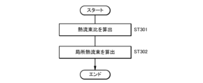
- the processor may obtain the heat flux ratio stored in the storage device, calculate an actual average heat flux for the heating tube based on the heat quantity of the heated fluid flowing into the heating tube and the heat quantity of the heated fluid flowing out of the heating tube, and obtain the local heat flux based on the heat flux ratio and the actual average heat flux.
- the load of the calculation process of the local heat flux is reduced by using the heat flux ratio obtained in the past.
- the heat flux ratio obtained in the past there is an advantage in that it is no longer necessary to measure the target point temperature of the heating pipe, and there is no need to obtain the environmental temperature or correct it.
- a storage device may be further provided, and the processor may store the operating conditions of the heating furnace and the environmental temperature under those operating conditions in the storage device, and construct a machine learning model that uses the operating conditions stored in the storage device as input and outputs the environmental temperature.
- a machine learning model constructed based on past operating conditions of the heating furnace and the environmental temperatures under those operating conditions can be used to accurately obtain the corresponding environmental temperature from the current operating conditions (or planned operating conditions).
- the processor may acquire the environmental temperature by inputting new operating conditions of the heating furnace into the machine learning model, and calculate the local heat flux based on the acquired environmental temperature and the target point temperature on the outer surface of the object.
- the local heat flux can be calculated with high accuracy based on the environmental temperature obtained by the machine learning model.
- the operating conditions may include the combustion conditions of the heating furnace and the operating conditions of the burners in the heating furnace.
- the environmental temperature (and therefore the local heat flux) can be obtained with high accuracy using appropriate operating conditions.
- the temperature sensor may include a wavelength distribution type radiation thermometer.
- the temperature of the target point can be obtained with high accuracy even when the measurement is performed without contacting the target.
- the processor may generate an image that visualizes the distribution of the local heat flux.
- the user can easily check various phenomena occurring within the heating furnace (e.g., the occurrence of coking or film boiling) based on an image that visualizes the distribution of local heat flux.
- various phenomena occurring within the heating furnace e.g., the occurrence of coking or film boiling
- the heating pipe has one or more segments (G 1 -G 9 ) and a plurality of target points set for each segment, and the processor may obtain a temperature distribution of the object measured by a thermograph (32) using the estimated environmental temperature.
- This aspect makes it possible to obtain the temperature of objects in a heating furnace over a wide range using thermography.
- the processor may obtain the temperature in the temperature distribution of the object as the object point temperature.
- This embodiment allows for greater freedom in setting the target point on the object. It also has the advantage of making it easy to obtain the target point temperature over a wide range of the object.
- one aspect of the present invention is a heat flux acquisition system including the above heat flux acquisition device, which includes a wavelength distribution type radiation thermometer (23) included in the temperature sensor, and a thermograph (22) for acquiring the environmental temperature.
- This aspect makes it easy to obtain the local heat flux of an object inside a heating furnace.
- one aspect of the present invention is a heat flux acquisition method for acquiring the heat flux of an object (12) in a heating furnace (2), in which a computer (4) acquires an object point temperature measured by a temperature sensor (12) for an object point on the outer surface of the object, acquires an environmental temperature corresponding to the object point, and calculates a local heat flux for the object point based on the object point temperature and the corresponding environmental temperature.
- This aspect makes it easy to obtain the local heat flux of an object inside a heating furnace.
- the above aspect makes it easy to obtain the local heat flux of an object inside a heating furnace.
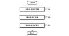
- FIG. 1 is a flow chart showing a flow of a heat flux acquisition process performed by the heat flux acquisition device 4.
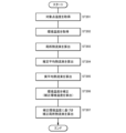
- FIG. 5 is a flow diagram showing a first modified example of the heat flux acquisition process shown in FIG.
- FIG. 5 is a flow diagram showing a second modified example of the heat flux acquisition process shown in FIG.
- the heat flux acquisition system 1 includes an on-site equipment 3 for acquiring various information and measurement data related to the heating furnace 2.
- the heat flux acquisition system 1 also includes a heat flux acquisition device 4 for acquiring the heat flux of an object in the heating furnace 2.
- the on-site equipment 3 and the heat flux acquisition device 4 can communicate with each other via a communication network 5 such as a LAN (Local Area Network) or the Internet.
- a communication network 5 such as a LAN (Local Area Network) or the Internet.
- the on-site equipment 3 and the heat flux acquisition device 4 may also be directly connected by a communication cable.
- the heating furnace 2 has a known configuration used as plant equipment.
- the heating furnace 2 is a tubular heating furnace, but may have other configurations.
- Inside the casing 11 i.e., inside the heating furnace 2, there are provided a heating tube 12 through which the heated fluid flows, and a combustion device 13 including a burner.
- the heating tube 12 is formed of a circular tube, but may have other configurations.
- the heating tube 12 is heated by the heat of the flame or combustion gas of the combustion device 13.
- Inside the heating furnace 2 there are provided an upper area 14 that heats (or preheats) the heated fluid, and a lower area 15 that heats the heated fluid heated in the upper area 14.
- multiple observation windows are provided in appropriate positions (e.g., in the side wall) of the casing 11 to observe the inside of the heating furnace 2.
- the target (i.e., object) for obtaining heat flux in the heating furnace 2 is the heating tube 12, which is heated mainly by radiative heat transfer (i.e., radiation heat transfer).
- the target for obtaining such heat flux is not limited to the heating tube 12, and may be other components in the heating furnace 2 (e.g., the inner wall of the casing 11).
- a slab in a heating furnace for heating slabs may be the target for obtaining heat flux.
- the on-site equipment 3 includes a measuring device 21 for the heated fluid, a thermograph 22, a two-color thermometer 23 (an example of a temperature sensor), and a terminal device 24.
- the measuring instruments 21 for the heated fluid are attached to appropriate locations of the heating pipe 12 (e.g., the inlet, outlet, and middle part of the heating pipe 12 for the heated fluid).
- the measuring instruments 21 may include a thermometer, a flowmeter, and a pressure gauge for measuring the temperature, flow rate, and pressure, respectively, of the heated fluid.
- the thermograph 22 has a known configuration and non-contactly measures the outer surface temperature of the heating tube 12 in a specified measurement area based on infrared rays emitted from the heating tube 12 in the heating furnace 2. Measurements using the thermograph 22 are performed through a viewing window in the heating furnace 2. Multiple thermographs 22 may be provided to simultaneously measure multiple measurement areas in the heating tube 12.
- the two-color thermometer 23 has a known configuration and non-contactly measures the temperature (hereinafter referred to as the target point) of a specific portion on the outer surface of the heating tube 12 based on two different measurement wavelengths. Measurement by the two-color thermometer 23 is performed through a sight glass, similar to the thermograph 22. Multiple two-color thermometers 23 may be provided to simultaneously measure multiple target points on the heating tube 12. Note that the measurement of the target point temperature of the heating furnace 2 is not limited to the two-color thermometer 23, and may be performed by other wavelength distribution type radiation thermometers. In some cases, the measurement of the target point temperature of the heating furnace 2 may be performed by a known thermometer (e.g., a thermocouple) that is installed in advance in the heating furnace 2.
- a known thermometer e.g., a thermocouple
- the terminal device 24 collects various measurement data measured on the heating furnace 2. Such measurement data includes data measured by the measuring device 21 for the heated fluid, the thermograph 22, and the two-color thermometer 23. Furthermore, the measurement data may include data obtained by performing a predetermined calculation process using the measured data (i.e., data measured indirectly).
- the terminal device 24 is communicatively connected to the heat flux acquisition device 4 via the communication network 5, and transmits the collected measurement data to the heat flux acquisition device 4 as appropriate.
- the terminal device 24 can also store specification data of the heating furnace 2 and transmit the data to the heat flux acquisition device 4.
- the specification data of the heating furnace 2 includes data required for calculation process for acquiring the heat flux by the heat flux acquisition device 4 (e.g., data related to the physical property values, size, position, etc. of the heating tube 12).
- the terminal device 24 may be used as a control device for controlling the operation of the heating furnace 2.
- the terminal device 24 is composed of a computer equipped with known hardware.
- the terminal device 24 is appropriately equipped with known hardware such as one or more processors, memory, a display, an input device, a network interface, and storage. At least some of the functions of the terminal device 24 can be realized by the processor executing a predetermined control program. Note that in the heat flux acquisition system 1, at least some of the functions of the terminal device 24 described above may be realized by multiple computers working together.
- the heat flux acquisition device 4 has a control unit 31, a memory unit 32, and a communication unit 33.
- the data acquisition unit 41 acquires measurement data and specification data related to the heating furnace 2 received from the terminal device 24 via the communication unit 33.
- the measurement data acquired by the measuring device 21 and the specification data of the heating furnace 2 are stored in the memory unit 32 as heating furnace data 51.
- the measurement data related to the temperature of the heating tube 12 acquired by the thermograph 22 and the two-color thermometer 23 are stored in the memory unit 32 as heating tube temperature data 52.
- the measurement data related to the environmental temperature acquired by the thermograph 22 i.e., the temperature around the heating tube 12 in the heating furnace 2 is stored in the memory unit 32 as environmental temperature data 53.
- the corresponding environmental temperature differs depending on the position of the part of the heating tube 12 (e.g., the relative position to the flame of the combustion device 13). As described later, the environmental temperature is indirectly measured by the thermograph 22 (i.e., calculated or estimated based on other measured data).
- the heating furnace data 51 includes position data within the heating furnace 2.
- position data may include, for example, global coordinate data corresponding to the position of each target point on the heating tube 12.
- the positions of the measurement points using the thermograph 22 or two-color thermometer 23 can also be determined using global coordinates (i.e., the measured temperature, etc. can be associated with global coordinates).
- coordinate data uniquely set for the heating furnace 2 may also be used.
- the heat flux calculation unit 42 calculates a local heat flux (an example of an estimated local heat flux) at a target point of the heating pipe 12 based on the heating pipe temperature data 52 (here, the target point temperature of each target point) and the environmental temperature data 53 (here, the environmental temperature corresponding to each target point). As described later, the heat flux calculation unit 42 may calculate a local heat flux based on a corrected environmental temperature. Furthermore, the heat flux calculation unit 42 can calculate an average heat flux (hereinafter referred to as an estimated average heat flux) for the entire heating pipe 12 based on the local heat fluxes at a plurality of target points.
- the estimated average heat flux does not necessarily have to be a heat flux for the entire heating pipe 12, and may be a heat flux for a predetermined section of the heating pipe 12 (for example, segments G 1 -G 9 described later).
- the heat flux calculation unit 42 may calculate the amount of heat input to the entire heating tube 12 (hereinafter referred to as the estimated average heat input amount) based on the amount of heat input at multiple target points instead of or in addition to the estimated average heat flux.
- the heat flux calculation unit 42 can calculate an average heat flux (hereinafter referred to as actual average heat flux) for the entire heated tube 12 based on the heat quantity of the heated fluid flowing into the heated tube 12 and the heat quantity of the heated fluid flowing out of the heated tube 12 (i.e., the amount of heat input to the heated fluid that has flowed through the heated tube 12).
- the actual average heat flux does not necessarily have to be the heat flux for the entire heated tube 12, and may be the heat flux for a predetermined section of the heated tube 12 (for example, segments G 1 -G 9 described later).
- the heat flux calculation unit 42 may calculate or estimate the amount of heat input to the entire heating pipe 12 (hereinafter referred to as the actual average heat input amount) from the amount of heat input to the heated fluid that has flowed through the entire heating pipe 12, instead of or together with the actual average heat flux. Also, the actual average heat input amount may be calculated or estimated from the sum of the amounts of heat input to the heated fluid that has flowed through each section (e.g., segments G 1 -G 9 described later) of the heating pipe 12 that includes a plurality of target points.
- the actual average heat input amount may be calculated or estimated from the sum of the amounts of heat input to the heated fluid that has flowed through each section (e.g., segments G 1 -G 9 described later) of the heating pipe 12 that includes a plurality of target points.
- Heat flux data 54 Data relating to the local heat flux, estimated average heat flux, estimated average heat input, actual average heat flux, actual average heat input, etc. calculated by the heat flux calculation unit 42 are stored in the storage unit 32 as heat flux data 54.
- the heat flux calculation unit 42 can calculate the heat flux ratio between the actual average heat flux and the local heat flux at each target point, and store it in the storage unit 32 as heat flux data 54. This allows the heat flux calculation unit 42 to calculate the local heat flux based on the data of the heat flux ratio calculated in the past and the actual average heat flux, even if the operating conditions are changed.
- the heat flux ratio data is stored in the storage unit 32 as part of the heat flux data 54.
- the environmental temperature correction unit 43 obtains the corrected environmental temperature by correcting the environmental temperature received from the terminal device 24 based on the estimated average heat flux and the actual average heat flux.
- the corrected environmental temperature data calculated by the environmental temperature correction unit 43 is stored in the memory unit 32 as environmental temperature data 53. More specifically, when the corrected environmental temperature is calculated by the environmental temperature correction unit 43, the environmental temperature already stored in the memory unit 32 is updated by the corrected environmental temperature. Note that the environmental temperature correction unit 43 may obtain the corrected environmental temperature by correcting the initial value of the environmental temperature previously stored in the memory unit 32, instead of the environmental temperature received from the terminal device 24.
- the heat flux distribution generating unit 44 generates an image (hereinafter referred to as a heat flux visualization image) in which the distribution of local heat flux at multiple target points of the heating tube 12 is visualized by coloring (i.e., color change) based on the data of the local heat flux calculated by the heat flux calculating unit 42.
- the heat flux visualization image is transmitted to the terminal device 24 and displayed on the display of the terminal device 24. This allows the user to easily check various phenomena occurring in the heating furnace 2 (for example, the occurrence of coking or film boiling in the heating tube 12) based on the heat flux visualization image.
- Data related to the heat flux visualization image generated by the heat flux distribution generating unit 44 is stored in the storage unit 32 as heat flux image data 55.
- the control unit 31 can acquire temperature measurement data of the thermograph 22 (i.e., the temperature distribution of the heating tube 12 in a specified measurement area) corrected using the corrected environmental temperature, and acquire the temperature in the temperature distribution as the target point temperature. This enables the control unit 31 to calculate the local heat flux for more locations (locations on the outer surface of the heating tube 12 other than the target points measured by the two-color thermometer 23) based on the target point temperatures acquired by measurement with the thermograph 22 and the corresponding environmental temperatures.
- the control unit 31 can execute a process for acquiring the heat flux of the heating pipe 12 in the heating furnace 2 (hereinafter referred to as the heat flux acquisition process).
- the memory unit 32 may be configured with hardware such as storage (an example of a memory device) for storing data and information necessary for the heat flux acquisition process by the heat flux acquisition device 4 as described above.
- storage an example of a memory device
- the communication unit 33 may be configured with hardware including an antenna, a communication circuit, etc., for the heat flux acquisition device 4 to communicate with the terminal device 24, etc., via the communication network 5.
- the control unit 31 may also function as a communication control unit that controls the communication between the communication unit 33 and the terminal device 24, etc.
- the heat flux acquisition device 4 is composed of a computer such as a server equipped with known hardware.
- the heat flux acquisition device 4 is appropriately equipped with known hardware such as one or more processors, memory, a display, an input device, a network interface, and storage.
- At least some of the functions of each of the units 41-44 in the control unit 31 can be realized by the processor executing a predetermined control program.
- the processor executing a predetermined control program.
- the functions of the heat flux acquisition device 4 described above may be realized by multiple computers working together.
- at least some of the functions of the heat flux acquisition device 4 may be possessed by the terminal device 24.
- the heating tubes 12 are arranged in a three-dimensional space, but for the sake of convenience, they are arranged in planar rectangular areas A1-A9 observed from one side of the heating furnace 2 (e.g., the observation window side).
- the heating tubes 12 extend from top to bottom while reciprocating left and right within the heating furnace 2.
- the heated fluid flows in from the inlet 12A of the heating tube 12, flows through the heating tube 12 and is heated, and then flows out from the outlet 12B of the heating tube 12.
- the heating tube 12 and the heated fluid flowing through it are heated by the flame or exhaust gas of a burner arranged below.
- each of the portions of the heating pipe 12 in the areas A1- A9 (hereinafter, each of the portions will be referred to as segments G 1 -G 9 ) are set to S 1 -S 9 , respectively.
- the environmental temperatures of the areas A1-A9 corresponding to the segments G 1 -G 9 of the heating pipe 12 are set to T B1 -T B9 , respectively.
- each of the segments G 1 -G 9 may be divided into a plurality of segments in the longitudinal direction, so that a plurality of sub-segments may be set for each of the segments G 1 -G 9.
- the target points P 1-1 -P 1-8 of the heating pipe 12 may be set, for example, to the representative positions (for example, the center in the longitudinal direction) of the sub-segments G 1-1 -G 1-8 . Furthermore, the target point temperatures T R1-1 to T R1-8 of the target points P 1-1 to P 1-8 become the representative temperatures of the sub-segments G 1-1 to G 1-8 . Target points and sub-segments are set for the other areas A2 to A9 in the same manner as for area A1.
- the number and size (i.e., range) of the areas, segments, and subsegments set for the heating furnace 2 are not limited to those shown in FIG. 3 and may be modified in various ways. Also, subsegments may be omitted.
- target point temperatures T R1-1 -T R1-8 measured by the two-color thermometer 23 are acquired (ST101).
- the heat flux acquisition device 4 acquires an environmental temperature T B1 (an example of an estimated environmental temperature) obtained by tuning during measurement by the thermograph 22, which will be described later, for each of the target points P 1-1 to P 1-8 (ST102).
- T B1 an example of an estimated environmental temperature
- the heat flux acquisition device 4 calculates the local heat fluxes q1-2 - q1-8 for each of the target points P1-1 - P1-8 based on the target point temperatures T1-1 - T1-8 and the environmental temperature T1 (ST103).
- the local heat flux q1-1 [W/ m2 ] at the target point P1-1 can be obtained from the following formula (1).
- T R1-1 Outer surface temperature at target point P 1-1 of heating tube 12 [K]
- T B1 Ambient temperature of area A1 [K]
- ⁇ emissivity of the heating tube 12
- Stefan-Boltzmann constant (5.67 ⁇ 10-8 [W/( m2 ⁇ K4 )])
- the local heat fluxes q 1-2 -q 1-8 [W/m 2 ] at the other target points P 1-2 -P 1-8 can also be obtained in the same manner as the local heat flux q 1-1 at the target point P 1-1 .
- the heat flux acquisition device 4 can acquire local heat flux throughout the entire heating tube 12 by repeatedly executing the same process as steps ST101-ST103 described above for the other areas A2-A9.
- E(T) [J] of the infrared rays incident on the thermograph 22 in measuring the temperature of the heating tube 12 can be expressed by the following formula (2).
- E(T) ⁇ E(T R )+(1 ⁇ ) ⁇ E(T B )...(2)
- the symbols are as follows: E(T R ): Radiant energy from the heating tube 12 [J]
- T Temperature reading by thermography 22 [K]
- T R Outer surface temperature of the heating tube 12 (i.e., true temperature) [K]
- T B Ambient temperature [K] ⁇ : emissivity of the heating tube 12
- the measurement value of the two-color thermometer 23 can be used as the outer surface temperature TR of the heating tube 12.
- the two-color thermometer 23 i.e., a wavelength distribution type radiation thermometer
- the user can set the environmental temperature T B so that the temperature indication value T by the thermograph 22 at a certain target point matches the measurement value T Rm by the two-color thermometer 23 at the same target point.
- T 1-j Temperature indication value [K] of the target point by the thermograph 22
- the environmental temperatures T B2 -T B9 of the other areas A2-A9 can be set in the same manner as the environmental temperature T B1 of the area A1.
- the set environmental temperatures T B1 -T B9 are input to the terminal device 24 and transmitted to the heat flux acquisition device 4.
- Such tuning during measurement by the thermographer 22 may be performed automatically without user operation.
- the thermographer 22 can acquire the target point temperature T Ri-j measured by the two-color thermometer 23, for example, through short-range communication with the two-color thermometer 23.
- the local heat flux calculated in step ST103 (for example, local heat flux q 1-2 -q 1-8 [W/m 2 ]) is a heat flux value at a predetermined portion in the circumferential direction of the circular heating tube 12.
- the heat flux and temperature in the circumferential direction may differ depending on the relative position with respect to the flame of the combustion device 13.
- the heat flux distribution in the circumferential direction of the tube can be determined based on the tube diameter, tube space, and arrangement, for example, in accordance with API (American Petroleum Institute) 530. Similarly, by appropriately setting the ratio to the local heat flux obtained in ST103, the heat flux (i.e., three-dimensional heat flux distribution) in each part in the circumferential direction of the heating tube 12 can be obtained.
- the average local heat flux in the circumferential direction in a specific subsegment can be obtained, for example, by using a flame front ratio ⁇ 1, and when the flame front ratio in the subsegment G 1-1 of the area A1 is ⁇ 1, the average local heat flux q 1-1ave can be obtained as q 1-1 / ⁇ 1.
- steps ST201-ST203 similar to steps ST101-ST103 in FIG. 4 are executed as shown in FIG. 5. This allows the local heat flux to be acquired throughout the entire heating tube 12 (i.e., in areas A1-A9).
- the heat flux acquisition device 4 calculates an estimated average heat flux (ST204).
- the heat flux acquisition device 4 first calculates an estimated segment average heat flux q1total for the segment G1 for the area A1 based on a weighted average using the outer surface areas S1-1-S1-8 of the sub-segments G1-1 - G1-8 as weights for the local heat fluxes q1-1-q1-8 for the corresponding target points P1-1 - P1-8 .
- the above-mentioned average local heat flux in the circumferential direction may be used as the value of q1-1 - q1-8 .
- the estimated segment average heat flux q 1total [W/m 2 ] for the segment G1 can be obtained from the following equation (4).
- the estimated segment average heat fluxes q 2total -q 9total for the segments G2-G9 in the areas A2-A9 can also be determined in the same manner as the estimated segment average heat flux q 1total for the segment G1.
- the heat flux acquisition device 4 can calculate the average value of these estimated segment average heat fluxes q 1total -q 9total as the estimated average heat flux q AVG in the entire heating tube 12.
- the heat flux acquisition device 4 calculates the actual average heat flux (ST205).
- the heat flux acquisition device 4 can calculate the actual average heat flux q REAL [W/m 2 ] from the following formula (5).
- q REAL MF ⁇ (H OUT - H IN )/S ALL ...(5)
- M F Mass flow rate of heated fluid [kg/s]
- H IN Specific enthalpy of the heated fluid flowing into the heating tube 12 [J/kg]
- H OUT Specific enthalpy of the heated fluid flowing out of the heating tube 12 [J/kg]
- the heat flux acquisition device 4 corrects the environmental temperature acquired in ST202 so that the estimated average heat flux q AVG in formula (4) coincides with the actual average heat flux q REAL in formula (5) (ST206). In other words, the heat flux acquisition device 4 calculates the corrected environmental temperature so that the estimated average heat flux q AVG coincides with the actual average heat flux q REAL .
- the heat flux acquisition device 4 calculates a corrected local heat flux based on the calculated corrected ambient temperature, similar to step ST202 (ST207).
- the heat flux acquisition device 4 can acquire local heat flux throughout the entire heating tube 12.
- the heat flux acquisition device 4 can set one of the segments G1 - G9 (segment G1 in this case) as the representative segment and the other segments (segments G2 - G9 in this case) as subordinate segments. Furthermore, the heat flux acquisition device 4 can set temperature ratios between the environmental temperatures T B2 -T B9 corresponding to the subordinate segments G2 - G9 , respectively, and the environmental temperature T B1 corresponding to the representative segment G1 . Each set temperature ratio is stored in the storage unit 32 as a part of the environmental temperature data 53.
- the temperature ratio ⁇ B2 between the environmental temperature T B2 corresponding to the subordinate segment G2 and the environmental temperature T B1 corresponding to the representative segment G1 can be expressed as a ratio of their fourth powers, as shown in the following equation (6).
- T B2 4 ⁇ B2 ⁇ T B1 4 ...(6)
- the temperature ratios ⁇ B3 - ⁇ B9 between the environmental temperatures T B3 -T B9 and T B1 corresponding to the other subordinate segments G 3 -G 9 , respectively, can be expressed in the same manner as the temperature ratio ⁇ B2 for the subordinate segment G2.
- the heat flux acquisition device 4 can acquire (or calculate) the environmental temperature T B1 of the representative segment G1 and newly calculate the environmental temperatures T B2 - T B9 of the subordinate segments G2-G9 from the environmental temperature T B1 , even if, for example, the operating conditions of the heating furnace 2 are changed. This reduces the load of the calculation process of the environmental temperature (and therefore the local heat flux) performed by the heat flux acquisition device 4.
- the environmental temperature of the subordinate segment is calculated from the environmental temperature of the representative segment and the environmental temperature ratio obtained from the operating data, and the heat flux at each target point is obtained using the target point temperatures and the environmental temperatures at each target point of all segments.
- the target point temperature may be a value measured by a temperature sensor, or may be a value calculated by a separate calculation.
- the local heat flux q i-j at a target point can be expressed as the following formula (7) using the outer surface temperature (i.e., target point temperature) T Ri-j [K] and the inner surface temperature T Ii-j [K] of the heating tube 12 at the target point, as well as the thermal resistance R i-j [m 2 ⁇ K/W].
- R Ri-j Thermal resistance of scale attached to the outer surface of the heating tube [ m2 K/W]
- R Ii-j Thermal resistance of the scale attached to the inner surface of the heating tube [ m2 ⁇ K/W]
- h i-j Heat transfer coefficient of the flow inside the tube [W/(m K)]
- the inner surface temperature T Ii-j [K] corresponds to the temperature of the heated fluid inside the pipe at the target point and can be expressed as the following equation (8).
- T R1-1 the outer surface temperature [K] at the target point P 1-1 of the heating pipe 12
- the outer surfaces of the other target points can also be calculated in the same manner as for the target point P 1-1 .
- the operating conditions of the heating furnace 2 include the combustion conditions in the heating furnace 2 (e.g., fuel composition, fuel pressure, fuel flow rate, etc.).
- the operating conditions can also include the operating conditions of each burner (fuel supply (injection) pressure, air volume, etc.) and the conditions inside the furnace (furnace temperature, flame shape and size), etc.
- the heat flux acquisition device 4 acquires data on the current operating conditions (or planned operating conditions) of the heating furnace 2, and can estimate data on the environmental temperatures T B1 -T B9 of each segment G1 -G9 using a machine learning model.
- the machine learning model may be stored in a server or the like that can communicate with the heat flux acquisition device 4 via the communication network 5. Also, data on past operating conditions in the heating furnace 2 and on each local heat flux under each operating condition may be prepared, and the heat flux acquisition device 4 may use this data as training data to construct a machine learning model.
- the heat flux acquisition device 4 may also use a machine learning model constructed by a computer such as another information processing device.
- Heat flux acquisition system 2 Heating furnace 3: On-site equipment 4: Heat flux acquisition device 5: Communication network 11: Casing 12: Heating pipe 12A: Inlet 12B: Outlet 13: Combustion device 14: Upper area 15: Lower area 21: Measuring instrument 22: Thermography 23: Two-color thermometer 24: Terminal device 31: Control unit 32: Memory unit 33: Communication unit 41: Data acquisition unit 42: Heat flux calculation unit 43: Ambient temperature correction unit 44: Heat flux distribution generation unit 51: Heating furnace data 52: Heating pipe temperature data 53: Ambient temperature data 54: Heat flux data 55: Heat flux image data A1-A9: Areas G1 - G9 : Segments G1-1 - G1-8 : Sub-segments
Landscapes
- Chemical & Material Sciences (AREA)
- Engineering & Computer Science (AREA)
- Combustion & Propulsion (AREA)
- Physics & Mathematics (AREA)
- General Physics & Mathematics (AREA)
- Radiation Pyrometers (AREA)
Abstract
Description
q1-1=ε・σ(TB1 4-TR1-1 4) ・・・(1)
ここで、各記号は以下に示す通りである。
TR1-1:加熱管12の対象点P1-1における外表面温度 [K]
TB1:エリアA1の環境温度[K]
ε:加熱管12の放射率
σ:ステファンボルツマン定数(5.67 × 10⁻⁸ [W/(m2・K4)])
E(T)=ε・E(TR)+(1-ε)・E(TB) ・・・(2)
ここで、各記号は以下に示す通りである。
E(TR):加熱管12からの放射エネルギ[J]
E(TB):加熱管12の外表面での環境反射エネルギ[J]
T:サーモグラフィ22による温度指示値[K]
TR:加熱管12の外表面温度(すなわち、真温度)[K]
TB:環境温度[K]
ε:加熱管12の放射率

ここで、各記号は以下に示す通りである。
T1-j:サーモグラフィ22による対象点の温度指示値[K]
TR1-j:対象点温度
ただし、j(=1, 2, ・・・,8)はサブセグメント番号である。

ここで、各記号は以下に示す通りである。
q1-j:対象点P1-jに関する局所熱流束 [W/m2]
S1-j:サブセグメントG1-jの外表面積[m2]
ただし、j(=1, 2, ・・・,8)はサブセグメント番号である。
qREAL=MF・(HOUT-HIN)/SALL ・・・(5)
ここで、各記号は以下に示す通りである。
MF:被加熱流体の質量流量[kg/s]
HIN:加熱管12に流入する被加熱流体の比エンタルピー[J/kg]
HOUT:加熱管12から流出する被加熱流体の比エンタルピー[J/kg]
SALL:加熱管12の全体の表面積(=S1+S2+・・・+S9) [m2]
次に、熱流束取得処理の一部を改変した別法1について説明する。別法1について以下で特に言及しない事項については、上述の熱流束取得処理におけるステップST201-ST207と同様である。
TB2 4=αB2・TB1 4 ・・・(6)
ここで、Ri-j=RWi-j+RRi-j+RIi-j+(1/hi-j)であり、各記号は以下に示す通りである。なお、hi-jは、API530に基づき取得することができる。
RWi-j:加熱管の熱抵抗=tWij/λ[m2・K/W]
(ただし、tWij:管の肉厚[m]、λ:管の熱伝導率[W/(m・K)])
RRi-j:加熱管の外表面に付着したスケールの熱抵抗[m2・K/W]
RIi-j:加熱管の内表面に付着したスケールの熱抵抗[m2・K/W]
hi-j:管内流の熱伝達率[W/(m・K)]

ここで、各記号は以下に示す通りである。
qi-j:局所熱流束[W/m2]
Tfirst:被加熱流体の流入時温度(初期温度)[K]
Si-j:対象点までの管路の表面積[m2]
γ:火炎面比率
MF:被加熱流体の質量流量[kg/s]
Cp:比熱[J/(kg・K)]

次に、熱流束取得処理の一部を改変した別法2について説明する。別法2について以下で特に言及しない事項については、上述の熱流束取得処理(図5参照)と同様である。
2 :加熱炉
3 :現場設備
4 :熱流束取得装置
5 :通信ネットワーク
11 :ケーシング
12 :加熱管
12A:入口
12B:出口
13 :燃焼装置
14 :上部エリア
15 :下部エリア
21 :計測機器
22 :サーモグラフィ
23 :二色温度計
24 :端末装置
31 :制御部
32 :記憶部
33 :通信部
41 :データ取得部
42 :熱流束算出部
43 :環境温度補正部
44 :熱流束分布生成部
51 :加熱炉データ
52 :加熱管温度データ
53 :環境温度データ
54 :熱流束データ
55 :熱流束画像データ
A1-A9:エリア
G1-G9:セグメント
G1-1-G1-8:サブセグメント
Claims (22)
- 加熱炉内における対象物の熱流束を取得する熱流束取得装置であって、
前記対象物の熱流束を取得するための処理を実行するプロセッサを備え、
前記プロセッサは、
前記対象物の外表面における対象点について温度センサによって測定された対象点温度を取得し、
前記対象点に対応する環境温度を取得し、
前記対象点温度およびそれに対応する前記環境温度に基づき、前記対象点に関する局所熱流束を算出する、
熱流束取得装置。 - 前記局所熱流束は、前記環境温度に基づいて算出される前記対象物に向けて放射されるエネルギと、前記対象点温度から算出される前記対象物から放射されるエネルギとに基づいて算出される、請求項1に記載の熱流束取得装置。
- 前記加熱炉は、管式加熱炉であり、
前記対象物は、前記管式加熱炉の加熱管を含む、請求項1に記載の熱流束取得装置。 - 前記環境温度は、サーモグラフィによる前記対象点の測定において、前記対応する対象点温度に基づき推定される推定環境温度である、請求項1から請求項3の何れか1項に記載の熱流束取得装置。
- 前記環境温度は、演算によって求められる補正環境温度であり、
前記加熱管は、1以上のセグメント及び当該各セグメントに対してそれぞれ設定される複数の対象点を有し、
前記補正環境温度は、少なくとも、前記各対象点について前記温度センサによってそれぞれ測定された対象点温度と、前記加熱管に流入する被加熱流体の熱量および前記加熱管から流出する前記被加熱流体の熱量とに基づき算出される、請求項3に記載の熱流束取得装置。 - 前記プロセッサは、
前記各対象点温度を取得し、
前記各セグメントにそれぞれ対応する炉内の推定環境温度であって、前記対応する各対象点温度に基づき推定される、推定環境温度を取得し、
前記各対象点温度およびそれに対応する前記推定環境温度に基づき、前記各対象点に関する推定局所熱流束を算出し、
前記推定局所熱流束に基づき、前記各セグメントに関する推定セグメント平均熱流束又は推定セグメント入熱量を算出すると共に、当該推定セグメント平均熱流束又は推定セグメント入熱量に基づいて、前記加熱管に関する推定平均熱流束又は推定入熱量を取得し、
前記加熱管に流入する前記被加熱流体の熱量および前記加熱管から流出する前記被加熱流体の熱量に基づき、前記加熱管に関する実平均熱流束又は実入熱量を算出し、
前記推定平均熱流束を前記実平均熱流束に一致させるように、又は前記推定入熱量を前記実入熱量に一致させるように、前記推定環境温度を補正することによって前記補正環境温度を算出する、請求項5に記載の熱流束取得装置。 - 前記各セグメントには、前記各対象点にそれぞれ対応して設定されたサブセグメントが含まれ、
前記プロセッサは、
前記各サブセグメントの表面積を、それぞれ対応する前記対象点に関する前記局所熱流束の重みとして用いた加重平均に基づき、前記各セグメントに関する前記推定セグメント平均熱流束を算出する、請求項6に記載の熱流束取得装置。 - 前記加熱管は、1つの代表セグメントおよび当該代表セグメント以外の従属セグメントを含む複数のセグメントを有し、
前記従属セグメントの前記推定環境温度は、前記代表セグメントの前記推定環境温度に対する温度比を用いて表され、
前記プロセッサは、
前記推定平均熱流束を前記実平均熱流束に一致させるように、又は前記推定入熱量を前記実入熱量に一致させるように、前記代表セグメントの補正環境温度を算出し、
前記代表セグメントの前記補正環境温度と前記温度比とに基づいて、前記従属セグメントの補正環境温度を算出する、請求項7に記載の熱流束取得装置。 - 前記従属セグメントの前記推定環境温度と、前記代表セグメントの前記推定環境温度との前記温度比を記憶する記憶装置を更に備える、請求項8に記載の熱流束取得装置。
- 前記プロセッサは、
前記各対象点温度を取得し、
前記代表セグメントの前記補正環境温度および前記従属セグメントの前記補正環境温度を取得し、
前記対象点温度ならびにそれに対応する前記代表セグメントの前記補正環境温度および前記従属セグメントの前記補正環境温度に基づき、前記対象点に関する局所熱流束を算出する、請求項9に記載の熱流束取得装置。 - 前記プロセッサは、さらに前記代表セグメントの前記補正環境温度および前記従属セグメントの前記補正環境温度に基づき、前記対象点に関する対象点温度を算出する、請求項10に記載の熱流束取得装置。
- 記憶装置を更に備え、
前記プロセッサは、さらに、
前記加熱管に流入する被加熱流体の熱量および前記加熱管から流出する前記被加熱流体の熱量に基づき、前記加熱管に関する実平均熱流束を算出し、
前記実平均熱流束と前記局所熱流束との熱流束比を算出し、当該熱流束比を前記記憶装置に記憶させる、請求項3に記載の熱流束取得装置。 - 前記プロセッサは、
前記記憶装置に記憶された前記熱流束比を取得し、
前記加熱管に流入する被加熱流体の熱量および前記加熱管から流出する前記被加熱流体の熱量に基づき、前記加熱管に関する実平均熱流束を算出し、
前記熱流束比と、前記実平均熱流束とに基づいて、前記局所熱流束を取得する、請求項12に記載の熱流束取得装置。 - 記憶装置をさらに備え、
前記プロセッサは、
前記加熱炉の運転条件と、当該運転条件における前記環境温度とを前記記憶装置に記憶させ、
前記記憶装置に記憶された前記運転条件を入力とし、前記環境温度を出力する機械学習モデルを構築する、
請求項1に記載の熱流束取得装置。 - 前記プロセッサは、
前記加熱炉の新たな運転条件を前記機械学習モデルに入力することにより、前記環境温度を取得し、
前記取得された環境温度と、対象物の外表面における対象点温度とに基づいて、局所熱流束を算出する、
請求項14に記載の熱流束取得装置。 - 前記運転条件は、前記加熱炉の燃焼条件と、前記加熱炉内のバーナの稼働条件とを含む、請求項14又は15に記載の熱流束取得装置。
- 前記温度センサは、波長分布型の放射温度計を含む、請求項1に記載の熱流束取得装置。
- 前記プロセッサは、
前記局所熱流束の分布を可視化した画像を生成する、請求項1に記載の熱流束取得装置。 - 前記加熱管は、1以上のセグメント及び当該各セグメントに対して設定される複数の対象点を有し、
前記プロセッサは、前記推定環境温度を用いてサーモグラフィによって測定された前記対象物の温度分布を取得する、請求項6に記載の熱流束取得装置。 - 前記プロセッサは、
前記対象物の前記温度分布における温度を、前記対象点温度として取得する、請求項19に記載の熱流束取得装置。 - 請求項1に記載の熱流束取得装置を含む熱流束取得システムであって、
前記温度センサに含まれる波長分布型の放射温度計と、
前記環境温度を取得するためのサーモグラフィと、を含む、熱流束取得システム。 - 加熱炉内における対象物の熱流束を取得するための熱流束取得方法であって、
コンピュータが、
前記対象物の外表面における対象点について温度センサによって測定された対象点温度を取得し、
前記対象点に対応する環境温度を取得し、
前記対象点温度およびそれに対応する前記環境温度に基づき、前記対象点に関する局所熱流束を算出する、熱流束取得方法。
Priority Applications (2)
| Application Number | Priority Date | Filing Date | Title |
|---|---|---|---|
| PCT/JP2023/005898 WO2024176281A1 (ja) | 2023-02-20 | 2023-02-20 | 加熱炉の熱流束取得装置、熱流束取得システム、及び熱流束取得方法 |
| JP2025501913A JP7840481B2 (ja) | 2023-02-20 | 2023-02-20 | 加熱炉の熱流束取得装置、熱流束取得システム、及び熱流束取得方法 |
Applications Claiming Priority (1)
| Application Number | Priority Date | Filing Date | Title |
|---|---|---|---|
| PCT/JP2023/005898 WO2024176281A1 (ja) | 2023-02-20 | 2023-02-20 | 加熱炉の熱流束取得装置、熱流束取得システム、及び熱流束取得方法 |
Publications (1)
| Publication Number | Publication Date |
|---|---|
| WO2024176281A1 true WO2024176281A1 (ja) | 2024-08-29 |
Family
ID=92500577
Family Applications (1)
| Application Number | Title | Priority Date | Filing Date |
|---|---|---|---|
| PCT/JP2023/005898 Ceased WO2024176281A1 (ja) | 2023-02-20 | 2023-02-20 | 加熱炉の熱流束取得装置、熱流束取得システム、及び熱流束取得方法 |
Country Status (2)
| Country | Link |
|---|---|
| JP (1) | JP7840481B2 (ja) |
| WO (1) | WO2024176281A1 (ja) |
Citations (4)
| Publication number | Priority date | Publication date | Assignee | Title |
|---|---|---|---|---|
| JPH11108773A (ja) * | 1997-09-30 | 1999-04-23 | Nkk Corp | 金属板の温度測定装置及び熱延鋼帯の圧延方法 |
| JP2004027314A (ja) * | 2002-06-27 | 2004-01-29 | Jfe Steel Kk | 被加熱物の温度推定方法 |
| JP2015117921A (ja) * | 2013-12-20 | 2015-06-25 | 株式会社Ihi | 蒸発管の内部状態判定装置と方法 |
| JP2021196116A (ja) * | 2020-06-15 | 2021-12-27 | 三菱パワー株式会社 | 貫流ボイラの運転制御装置、運転制御方法、および貫流ボイラ |
-
2023
- 2023-02-20 WO PCT/JP2023/005898 patent/WO2024176281A1/ja not_active Ceased
- 2023-02-20 JP JP2025501913A patent/JP7840481B2/ja active Active
Patent Citations (4)
| Publication number | Priority date | Publication date | Assignee | Title |
|---|---|---|---|---|
| JPH11108773A (ja) * | 1997-09-30 | 1999-04-23 | Nkk Corp | 金属板の温度測定装置及び熱延鋼帯の圧延方法 |
| JP2004027314A (ja) * | 2002-06-27 | 2004-01-29 | Jfe Steel Kk | 被加熱物の温度推定方法 |
| JP2015117921A (ja) * | 2013-12-20 | 2015-06-25 | 株式会社Ihi | 蒸発管の内部状態判定装置と方法 |
| JP2021196116A (ja) * | 2020-06-15 | 2021-12-27 | 三菱パワー株式会社 | 貫流ボイラの運転制御装置、運転制御方法、および貫流ボイラ |
Also Published As
| Publication number | Publication date |
|---|---|
| JPWO2024176281A1 (ja) | 2024-08-29 |
| JP7840481B2 (ja) | 2026-04-03 |
Similar Documents
| Publication | Publication Date | Title |
|---|---|---|
| CN108535321B (zh) | 一种基于三维红外热成像技术的建筑热工性能检测方法 | |
| US20170148184A1 (en) | Methods for monitoring combustion process equipment | |
| CN105102921B (zh) | 用于监测蒸汽发生器中的操作条件的方法和系统 | |
| CN102374902B (zh) | 一种提高辐射温度计测温准确度的量子论修正方法 | |
| CN103983361B (zh) | 在线式网络测温热像仪标定方法 | |
| Cardone et al. | Temperature maps measurements on 3D surfaces with infrared thermography | |
| CN104101432B (zh) | 一种测量封闭空腔金属器具内壁温度分布的方法 | |
| CN111189552B (zh) | 一种甲烷水合物火焰温度测试装置及测温修正方法 | |
| CN104792423B (zh) | 一种可校准测温参数的测温方法和装置 | |
| JP7840481B2 (ja) | 加熱炉の熱流束取得装置、熱流束取得システム、及び熱流束取得方法 | |
| KR102452394B1 (ko) | 딥러닝 기반 열전대 온도센서 실측을 통한 측정대상의 전체 온도 분포 예측 장치 및 방법 | |
| KR101606057B1 (ko) | 에너지 표시 가정용 가스미터 및 가스량 측정방법 | |
| JP6834148B2 (ja) | 流速の評価方法、及び評価システム | |
| JP6686335B2 (ja) | 関係情報設定方法、流速計測方法、関係情報設定システム及び流速計測システム | |
| CN119618387A (zh) | 一种基于比色测温结合多光谱成像的温度场测试方法 | |
| Kostov et al. | Experimental determination of the heat exchange coefficient of industrial steam pipelines | |
| KR20240028629A (ko) | 동적상태에 적용 가능한 물리모델을 통한 현장측정 기반의 벽체 열관류율 산정 방법 | |
| CN115790866B (zh) | 基于辐射自校准的火焰温度测量方法、装置、设备及介质 | |
| Huang et al. | An analytical radiometric thermometry model for quantitative prediction and correction of the gas emission and absorption effects | |
| CN104180927B (zh) | 一种超高温炉膛标准温度的测定平台以及测定方法 | |
| JPWO2024176281A5 (ja) | ||
| KR20110137459A (ko) | 온도 측정값을 이용한 연소가스 물성치 추정 방법 및 장치 | |
| CN115184403A (zh) | 一种土壤温度-高程二维框架下土壤热通量测算方法 | |
| Buffington et al. | Statistical aggregation of heat flux measurements for Bayesian inference of a burner fire's radiative fraction | |
| Sudheer et al. | Partitioning of convective and radiative heat fluxes absorbed by a lumped body engulfed in a diffusion flame |
Legal Events
| Date | Code | Title | Description |
|---|---|---|---|
| 121 | Ep: the epo has been informed by wipo that ep was designated in this application |
Ref document number: 23923937 Country of ref document: EP Kind code of ref document: A1 |
|
| ENP | Entry into the national phase |
Ref document number: 2025501913 Country of ref document: JP Kind code of ref document: A |
|
| WWE | Wipo information: entry into national phase |
Ref document number: 2025501913 Country of ref document: JP |
|
| NENP | Non-entry into the national phase |
Ref country code: DE |
|
| 122 | Ep: pct application non-entry in european phase |
Ref document number: 23923937 Country of ref document: EP Kind code of ref document: A1 |