WO2024171545A1 - Inkjet head driving method and inkjet recording device - Google Patents
Inkjet head driving method and inkjet recording device Download PDFInfo
- Publication number
- WO2024171545A1 WO2024171545A1 PCT/JP2023/040926 JP2023040926W WO2024171545A1 WO 2024171545 A1 WO2024171545 A1 WO 2024171545A1 JP 2023040926 W JP2023040926 W JP 2023040926W WO 2024171545 A1 WO2024171545 A1 WO 2024171545A1
- Authority
- WO
- WIPO (PCT)
- Prior art keywords
- ink
- nozzle
- drive waveform
- waveform
- inkjet head
- Prior art date
Links
- 238000000034 method Methods 0.000 title claims abstract description 42
- LFQSCWFLJHTTHZ-UHFFFAOYSA-N Ethanol Chemical compound CCO LFQSCWFLJHTTHZ-UHFFFAOYSA-N 0.000 claims abstract description 59
- 239000002131 composite material Substances 0.000 claims description 62
- 239000000758 substrate Substances 0.000 claims description 39
- 230000004044 response Effects 0.000 claims description 18
- 229910052799 carbon Inorganic materials 0.000 claims description 14
- OKTJSMMVPCPJKN-UHFFFAOYSA-N Carbon Chemical compound [C] OKTJSMMVPCPJKN-UHFFFAOYSA-N 0.000 claims description 13
- 230000008859 change Effects 0.000 claims description 9
- 230000015556 catabolic process Effects 0.000 abstract description 6
- 238000006731 degradation reaction Methods 0.000 abstract description 6
- 230000032258 transport Effects 0.000 description 40
- 230000005499 meniscus Effects 0.000 description 36
- 244000208734 Pisonia aculeata Species 0.000 description 35
- 235000019441 ethanol Nutrition 0.000 description 35
- 239000010410 layer Substances 0.000 description 34
- 238000001035 drying Methods 0.000 description 30
- 235000001892 vitamin D2 Nutrition 0.000 description 20
- 238000010586 diagram Methods 0.000 description 17
- 230000008602 contraction Effects 0.000 description 16
- 230000004048 modification Effects 0.000 description 14
- 238000012986 modification Methods 0.000 description 14
- 125000004432 carbon atom Chemical group C* 0.000 description 11
- 238000004891 communication Methods 0.000 description 10
- 239000002904 solvent Substances 0.000 description 9
- 230000015654 memory Effects 0.000 description 8
- 230000000052 comparative effect Effects 0.000 description 7
- KFZMGEQAYNKOFK-UHFFFAOYSA-N Isopropanol Chemical compound CC(C)O KFZMGEQAYNKOFK-UHFFFAOYSA-N 0.000 description 6
- OKKJLVBELUTLKV-UHFFFAOYSA-N Methanol Chemical compound OC OKKJLVBELUTLKV-UHFFFAOYSA-N 0.000 description 6
- 238000002474 experimental method Methods 0.000 description 6
- LRHPLDYGYMQRHN-UHFFFAOYSA-N N-Butanol Chemical compound CCCCO LRHPLDYGYMQRHN-UHFFFAOYSA-N 0.000 description 5
- 150000001298 alcohols Chemical class 0.000 description 5
- BTANRVKWQNVYAZ-UHFFFAOYSA-N butan-2-ol Chemical compound CCC(C)O BTANRVKWQNVYAZ-UHFFFAOYSA-N 0.000 description 5
- BDERNNFJNOPAEC-UHFFFAOYSA-N propan-1-ol Chemical compound CCCO BDERNNFJNOPAEC-UHFFFAOYSA-N 0.000 description 5
- 230000006399 behavior Effects 0.000 description 4
- 230000000694 effects Effects 0.000 description 4
- 238000011156 evaluation Methods 0.000 description 4
- 239000007788 liquid Substances 0.000 description 4
- 239000000463 material Substances 0.000 description 4
- 230000003321 amplification Effects 0.000 description 3
- 239000003086 colorant Substances 0.000 description 3
- 230000007423 decrease Effects 0.000 description 3
- 230000006866 deterioration Effects 0.000 description 3
- 238000010438 heat treatment Methods 0.000 description 3
- 230000007246 mechanism Effects 0.000 description 3
- 238000003199 nucleic acid amplification method Methods 0.000 description 3
- 230000005856 abnormality Effects 0.000 description 2
- 239000000853 adhesive Substances 0.000 description 2
- 230000001070 adhesive effect Effects 0.000 description 2
- 230000001687 destabilization Effects 0.000 description 2
- 229910052451 lead zirconate titanate Inorganic materials 0.000 description 2
- HFGPZNIAWCZYJU-UHFFFAOYSA-N lead zirconate titanate Chemical compound [O-2].[O-2].[O-2].[O-2].[O-2].[Ti+4].[Zr+4].[Pb+2] HFGPZNIAWCZYJU-UHFFFAOYSA-N 0.000 description 2
- 239000000203 mixture Substances 0.000 description 2
- 238000007639 printing Methods 0.000 description 2
- 230000008569 process Effects 0.000 description 2
- 238000012545 processing Methods 0.000 description 2
- 230000003252 repetitive effect Effects 0.000 description 2
- 229910052710 silicon Inorganic materials 0.000 description 2
- 239000010703 silicon Substances 0.000 description 2
- 229910001220 stainless steel Inorganic materials 0.000 description 2
- 239000010935 stainless steel Substances 0.000 description 2
- 239000002033 PVDF binder Substances 0.000 description 1
- RTAQQCXQSZGOHL-UHFFFAOYSA-N Titanium Chemical compound [Ti] RTAQQCXQSZGOHL-UHFFFAOYSA-N 0.000 description 1
- 230000002745 absorbent Effects 0.000 description 1
- 239000002250 absorbent Substances 0.000 description 1
- 230000001133 acceleration Effects 0.000 description 1
- 229910002113 barium titanate Inorganic materials 0.000 description 1
- JRPBQTZRNDNNOP-UHFFFAOYSA-N barium titanate Chemical compound [Ba+2].[Ba+2].[O-][Ti]([O-])([O-])[O-] JRPBQTZRNDNNOP-UHFFFAOYSA-N 0.000 description 1
- 238000005452 bending Methods 0.000 description 1
- 238000007664 blowing Methods 0.000 description 1
- 238000009835 boiling Methods 0.000 description 1
- 238000004581 coalescence Methods 0.000 description 1
- 230000007547 defect Effects 0.000 description 1
- 230000000368 destabilizing effect Effects 0.000 description 1
- 238000001514 detection method Methods 0.000 description 1
- NKZSPGSOXYXWQA-UHFFFAOYSA-N dioxido(oxo)titanium;lead(2+) Chemical compound [Pb+2].[O-][Ti]([O-])=O NKZSPGSOXYXWQA-UHFFFAOYSA-N 0.000 description 1
- 238000006073 displacement reaction Methods 0.000 description 1
- 238000005516 engineering process Methods 0.000 description 1
- 239000004744 fabric Substances 0.000 description 1
- 230000006870 function Effects 0.000 description 1
- GQYHUHYESMUTHG-UHFFFAOYSA-N lithium niobate Chemical compound [Li+].[O-][Nb](=O)=O GQYHUHYESMUTHG-UHFFFAOYSA-N 0.000 description 1
- 229910052751 metal Inorganic materials 0.000 description 1
- 239000002184 metal Substances 0.000 description 1
- 239000007769 metal material Substances 0.000 description 1
- 239000000049 pigment Substances 0.000 description 1
- 239000002985 plastic film Substances 0.000 description 1
- 229920006255 plastic film Polymers 0.000 description 1
- 239000011092 plastic-coated paper Substances 0.000 description 1
- 229920002981 polyvinylidene fluoride Polymers 0.000 description 1
- 239000010970 precious metal Substances 0.000 description 1
- 239000010453 quartz Substances 0.000 description 1
- 239000011347 resin Substances 0.000 description 1
- 229920005989 resin Polymers 0.000 description 1
- 238000000926 separation method Methods 0.000 description 1
- VYPSYNLAJGMNEJ-UHFFFAOYSA-N silicon dioxide Inorganic materials O=[Si]=O VYPSYNLAJGMNEJ-UHFFFAOYSA-N 0.000 description 1
- 239000002356 single layer Substances 0.000 description 1
- 239000004094 surface-active agent Substances 0.000 description 1
- 230000008719 thickening Effects 0.000 description 1
- 239000010936 titanium Substances 0.000 description 1
- 229910052719 titanium Inorganic materials 0.000 description 1
- 230000007704 transition Effects 0.000 description 1
- 238000011144 upstream manufacturing Methods 0.000 description 1
- MECHNRXZTMCUDQ-RKHKHRCZSA-N vitamin D2 Chemical compound C1(/[C@@H]2CC[C@@H]([C@]2(CCC1)C)[C@H](C)/C=C/[C@H](C)C(C)C)=C\C=C1\C[C@@H](O)CCC1=C MECHNRXZTMCUDQ-RKHKHRCZSA-N 0.000 description 1
- 239000011653 vitamin D2 Substances 0.000 description 1
- XLYOFNOQVPJJNP-UHFFFAOYSA-N water Substances O XLYOFNOQVPJJNP-UHFFFAOYSA-N 0.000 description 1
- 230000003936 working memory Effects 0.000 description 1
Images


Classifications
-
- B—PERFORMING OPERATIONS; TRANSPORTING
- B41—PRINTING; LINING MACHINES; TYPEWRITERS; STAMPS
- B41J—TYPEWRITERS; SELECTIVE PRINTING MECHANISMS, i.e. MECHANISMS PRINTING OTHERWISE THAN FROM A FORME; CORRECTION OF TYPOGRAPHICAL ERRORS
- B41J2/00—Typewriters or selective printing mechanisms characterised by the printing or marking process for which they are designed
- B41J2/005—Typewriters or selective printing mechanisms characterised by the printing or marking process for which they are designed characterised by bringing liquid or particles selectively into contact with a printing material
- B41J2/01—Ink jet
- B41J2/015—Ink jet characterised by the jet generation process
- B41J2/04—Ink jet characterised by the jet generation process generating single droplets or particles on demand
- B41J2/045—Ink jet characterised by the jet generation process generating single droplets or particles on demand by pressure, e.g. electromechanical transducers
-
- B—PERFORMING OPERATIONS; TRANSPORTING
- B41—PRINTING; LINING MACHINES; TYPEWRITERS; STAMPS
- B41J—TYPEWRITERS; SELECTIVE PRINTING MECHANISMS, i.e. MECHANISMS PRINTING OTHERWISE THAN FROM A FORME; CORRECTION OF TYPOGRAPHICAL ERRORS
- B41J2/00—Typewriters or selective printing mechanisms characterised by the printing or marking process for which they are designed
- B41J2/005—Typewriters or selective printing mechanisms characterised by the printing or marking process for which they are designed characterised by bringing liquid or particles selectively into contact with a printing material
- B41J2/01—Ink jet
- B41J2/135—Nozzles
- B41J2/14—Structure thereof only for on-demand ink jet heads
-
- B—PERFORMING OPERATIONS; TRANSPORTING
- B41—PRINTING; LINING MACHINES; TYPEWRITERS; STAMPS
- B41J—TYPEWRITERS; SELECTIVE PRINTING MECHANISMS, i.e. MECHANISMS PRINTING OTHERWISE THAN FROM A FORME; CORRECTION OF TYPOGRAPHICAL ERRORS
- B41J2/00—Typewriters or selective printing mechanisms characterised by the printing or marking process for which they are designed
- B41J2/005—Typewriters or selective printing mechanisms characterised by the printing or marking process for which they are designed characterised by bringing liquid or particles selectively into contact with a printing material
- B41J2/01—Ink jet
- B41J2/17—Ink jet characterised by ink handling
- B41J2/18—Ink recirculation systems
-
- B—PERFORMING OPERATIONS; TRANSPORTING
- B41—PRINTING; LINING MACHINES; TYPEWRITERS; STAMPS
- B41M—PRINTING, DUPLICATING, MARKING, OR COPYING PROCESSES; COLOUR PRINTING
- B41M5/00—Duplicating or marking methods; Sheet materials for use therein
Definitions
- the present invention relates to a method for driving an inkjet head and an inkjet recording device.
- an inkjet recording device that forms an image by ejecting ink from nozzles provided in an inkjet head and landing it at a desired position.
- the inkjet head is equipped with a pressure chamber that communicates with the nozzle, and a piezoelectric element that deforms in response to the application of a voltage to cause a pressure change in the ink in the pressure chamber.
- a specific drive signal to the piezoelectric element, ink is ejected from the nozzle in response to the pressure change of the ink in the pressure chamber.
- Patent Document 1 discloses a technology in which multiple ink droplets are ejected from a nozzle in response to multiple drive signals, and these multiple ink droplets are combined and landed on a recording medium.
- the object of this invention is to provide an inkjet head driving method and inkjet recording device that can effectively prevent degradation of image quality.
- the present invention provides a method for driving an inkjet head, comprising: A method for driving an inkjet head capable of applying a pressure change to ink in a pressure chamber and ejecting ink droplets from a nozzle by deforming a piezoelectric element in response to application of a voltage signal of a unit drive waveform including one or more pulse waveforms, comprising: applying a voltage signal of a composite drive waveform including a plurality of the unit drive waveforms to the piezoelectric element, thereby ejecting a plurality of ink droplets from the nozzle, the ink droplets landing on a recording medium in a united state;
- the composite drive waveform includes at least four pulse waveforms within 4 AL from the start of application of a first pulse waveform, the composite drive waveform includes a first unit drive waveform and a second unit drive waveform that is applied at the end of the composite drive waveform and ejects ink droplets at a speed faster than that of the first unit drive wave
- the present invention relates to a method for driving an inkjet head, comprising:
- the ink contains the alcohol in an amount within the range of 20% by mass or more and 35% by mass or less based on the total mass of the ink.
- the present invention relates to a method for driving an inkjet head, comprising:
- the ink has a viscosity of 6 cP or less when ejected from the nozzle.
- the present invention as set forth in claim 4 is the method for driving an inkjet head as set forth in claim 1, further comprising the steps of:
- the maximum width of the nozzle opening is 23 ⁇ m or less.
- the present invention as set forth in claim 5 is the method for driving an inkjet head as set forth in claim 1, further comprising the steps of: the inkjet head includes a nozzle substrate having the nozzles; the nozzle has a tapered portion that penetrates the nozzle substrate and whose opening area in a cross section perpendicular to the ink ejection direction gradually increases from an opening side through which ink droplets are ejected toward an opposite side of the opening, In a cross section passing through the center of the opening and parallel to the discharge direction, the maximum value of the inclination angle of the surface of the tapered portion from the discharge direction is 40° or more.
- the present invention as set forth in claim 6 is the method for driving an inkjet head as set forth in claim 1, further comprising the steps of: During a period when ink droplets are not ejected from the nozzle, a voltage signal having a vibration waveform for vibrating the ink surface in the nozzle is applied to the piezoelectric element.
- a seventh aspect of the present invention provides the inkjet head driving method according to the first aspect, further comprising the steps of:
- the composite drive waveform is applied to the piezoelectric element at a frequency of 10 kHz or greater.
- the present invention relates to a method for driving an inkjet head, comprising:
- the voltage amplitude of the pulse waveform included in the second unit drive waveform is set to a value that causes the ink droplets to coalesce within 35 microseconds after application of the second unit drive waveform is completed.
- a ninth aspect of the present invention provides the inkjet head driving method according to the first aspect, further comprising the steps of: the number of unit drive waveforms included in the composite drive waveform is varied, thereby making it possible to adjust the volume of the ink droplets after the ink is combined to one of a plurality of different droplet volumes; The minimum droplet amount among the plurality of droplet amounts is 5 pl or less.
- a method for driving an inkjet head comprising the steps of: the inkjet head is connected to a circulation flow path passing through the inkjet head; During the ejection of ink by the composite drive waveform, ink that has not been ejected from the nozzle is circulated in the circulation flow path.
- the present invention provides an ink jet recording apparatus comprising: an inkjet head capable of applying a pressure change to ink in a pressure chamber and ejecting ink droplets from a nozzle by deforming a piezoelectric element in response to application of a voltage signal of a unit drive waveform including one or more pulse waveforms;
- a drive control unit that controls a voltage signal to be applied to the piezoelectric element; Equipped with the drive control unit applies a voltage signal of a composite drive waveform including a plurality of the unit drive waveforms to the piezoelectric element, thereby causing a plurality of ink droplets to be ejected from the nozzle in a united state and land on a recording medium;
- the composite drive waveform includes at least four pulse waveforms within 4 AL from the start of application of a first pulse waveform, the composite drive waveform includes a first unit drive waveform and a second unit drive waveform that is applied at the end of the composite drive waveform and ejects ink
- the present invention makes it possible to effectively prevent degradation of image quality.
- FIG. 1 is a diagram illustrating a schematic configuration of an inkjet recording apparatus.
- FIG. 2 is a schematic diagram illustrating a configuration of a head unit.
- FIG. 2 is a cross-sectional view showing an ink ejection mechanism of the inkjet head.
- 4 is a diagram showing a cross section of the nozzle substrate, the cross section passing through the center of the nozzle opening and perpendicular to the X direction.
- FIG. FIG. 2 is a block diagram showing the functional configuration of the inkjet recording apparatus.
- 4A and 4B are diagrams showing composite driving waveforms for ejecting ink in an inkjet recording apparatus.
- FIG. 13 is a diagram showing a composite drive waveform when a medium droplet is ejected.
- FIG. 1 is a diagram illustrating a schematic configuration of an inkjet recording apparatus.
- FIG. 2 is a schematic diagram illustrating a configuration of a head unit.
- FIG. 2 is a cross-sectional view showing an in
- FIG. 13 is a diagram showing a composite drive waveform when ejecting a small droplet.
- FIG. 2 is an enlarged view of a repeating waveform.
- 11A and 11B are diagrams illustrating the behavior of ink ejected by a first unit drive waveform.
- FIG. 13 is an enlarged view of a terminal waveform.
- FIG. 1 is a diagram showing the contents and results of an experiment.
- 13 is a diagram showing an ink circulation flow path in a head unit according to Modification 4.
- FIG. 1 is a diagram showing a schematic configuration of an inkjet recording apparatus 1 according to an embodiment of the present invention.
- the inkjet recording apparatus 1 includes a transport section 2 and a head unit 3 .
- the transport unit 2 includes two transport rollers 2a and 2b, and a ring-shaped transport belt 2c.
- the transport rollers 2a and 2b rotate around a rotation axis extending in the X direction of FIG. 1.
- the transport belt 2c is supported on the inside by the two transport rollers 2a and 2b.
- the transport roller 2a rotates in response to the operation of a transport motor (not shown), so that the transport belt 2c moves around the transport rollers 2a and 2b.
- the transport unit 2 transports the recording medium M in the moving direction of the transport belt 2c by the transport belt 2c moving around with the recording medium M placed on the transport surface of the transport belt 2c. Therefore, the moving direction of the transport belt 2c is the transport direction of the recording medium M.
- the transport direction is parallel to the Y direction of FIG. 1.
- the transport unit 2 may include a stage that reciprocates in the Y direction with the recording medium M placed thereon.
- the transport unit 2 may have a rotating cylindrical transport drum. The transport unit 2 moves the recording medium M placed on the cylindrical surface of the transport drum by rotating the transport drum.
- the recording medium M is, for example, a sheet of paper cut to a certain size.
- the recording medium M is fed onto the conveyor belt 2c by a paper feeder (not shown).
- An image is recorded on the recording medium M by ejecting ink from the head unit 3 onto the recording medium M.
- the recording medium M is then ejected from the conveyor belt 2c to a specified paper ejection section.
- Roll paper may also be used as the recording medium M.
- the material of the recording medium M is not particularly limited as long as it is possible to fix the ink that has landed on the surface.
- the recording medium M may be paper such as plain paper or coated paper, fabric, or sheet-like resin.
- the head unit 3 ejects ink at an appropriate timing based on image data onto the recording medium M being transported by the transport unit 2. In this way, the head unit 3 records an image on the recording medium M.
- the inkjet recording device 1 of this embodiment has four head units 3 corresponding to the four colors of ink, yellow (Y), magenta (M), cyan (C), and black (K). These four head units 3 are arranged in the order of Y, M, C, and K from the upstream side in the transport direction of the recording medium M.
- the head units 3 are also arranged so that the ink ejection direction is vertically downward. In FIG. 1, the -Z direction corresponds to the vertically downward direction.
- the number of head units 3 may be three or less, or five or more.
- Fig. 2 is a schematic diagram showing the configuration of the head unit 3.
- Fig. 2 is a plan view of the head unit 3 as viewed from the side facing the transport surface of the transport belt 2c.
- the head unit 3 has a plate-shaped support portion 3a and a plurality of inkjet heads 10.
- the plurality of inkjet heads 10 are fixed to the support portion 3a in a state where they fit into through holes in the support portion 3a.
- the head unit 3 of this embodiment has eight inkjet heads 10.
- the inkjet heads 10 are fixed to the support portion 3a in a state where their ink ejection surfaces are exposed from the through holes in the support portion 3a toward the conveyor belt 2c.
- the ink ejection surface of the inkjet heads 10 has openings for the nozzles N.
- each inkjet head 10 has four nozzle rows.
- Each nozzle row is made up of nozzles N arranged one-dimensionally at equal intervals in the X direction.
- the four nozzle rows of the inkjet head 10 are arranged with their positions in the X direction shifted from each other so that the positions of the nozzles N in the X direction do not overlap.
- the number of nozzle rows of the inkjet head 10 is not limited to four, and may be three or less, or five or more.
- the eight inkjet heads 10 are arranged in a staggered pattern so that the arrangement range of the nozzles N in the X direction is continuous.
- the arrangement range of the nozzles N included in the head unit 3 in the X direction covers the width in the X direction of the area of the recording medium M on which an image can be recorded.
- the head unit 3 is used in a fixed position when forming an image.
- the head unit 3 forms an image by a single pass method by ejecting ink from the nozzles N to each position at a predetermined interval in the transport direction in response to the transport of the recording medium M.
- FIG. 3 is a cross-sectional view showing the ink ejection mechanism of the ink-jet head 10.
- the inkjet head 10 includes a head chip 11 including a mechanism for ejecting ink from nozzles N.
- the +Z direction will also be referred to as the upward direction
- the -Z direction will also be referred to as the downward direction.
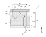
- the head chip 11 includes a nozzle substrate 110 having nozzles N, a flow path substrate 120 having a flow path communicating with the nozzles N, and an element substrate 130 having piezoelectric elements 13 and the like.
- the nozzle substrate 110, the flow path substrate 120, and the element substrate 130 are layered in this order.
- the nozzle substrate 110 and the flow path substrate 120 are bonded together with an adhesive or the like.
- the flow path substrate 120 and the element substrate 130 are also bonded together with an adhesive or the like.
- the nozzle substrate 110 has a plurality of nozzles N.
- the material of the nozzle substrate 110 may be silicon.
- FIG. 4 is a cross section of the nozzle substrate 110, which is a cross section passing through the center of the opening Na of the nozzle N and perpendicular to the X direction.
- the nozzle N penetrates the nozzle substrate 110.
- the end of the nozzle N on the -Z direction side is an opening Na from which ink droplets are ejected.
- the end of the nozzle N on the +Z direction side is a connection portion Nb that is connected to a through flow path 123 of the flow path substrate 120 described later.
- the opening Na is circular.
- the connection portion Nb is a circular opening.
- the nozzle N has a first nozzle flow path 111 and a second nozzle flow path 112.
- the first nozzle flow path 111 and the second nozzle flow path 112 communicate with each other in the Z direction.
- the first nozzle flow path 111 extends in the +Z direction from the opening Na.
- the second nozzle flow path 112 extends in the +Z direction from the end of the first nozzle flow path 111 on the +Z direction side to the connection portion Nb.
- the first nozzle flow path 111 and the second nozzle flow path 112 are tapered portions whose inner wall surfaces are inclined from the ejection direction in a cross section that passes through the center of the opening Na and is parallel to the ejection direction of the ink.
- the opening area of the first nozzle flow path 111 and the second nozzle flow path 112 in a cross section perpendicular to the ejection direction gradually increases from the opening Na side toward the connection portion Nb side. Therefore, the diameter d of the opening Na is smaller than the diameter of the connection portion Nb.
- the diameter d of the opening Na is preferably 23 ⁇ m or less.
- the diameter d of the opening Na corresponds to the maximum width of the opening Na.
- the inclination angle of the inner wall surface of the first nozzle flow path 111 from the discharge direction is ⁇ 1.
- the inclination angle of the inner wall surface of the second nozzle flow path 112 from the discharge direction is ⁇ 2.
- the inclination angles ⁇ 1 and ⁇ 2 satisfy ⁇ 1 ⁇ 2. It is preferable that the inclination angle ⁇ 2 is 40° or more. If the inclination angle ⁇ 2 is not constant, it is preferable that the maximum inclination angle of the inner wall surface of the second nozzle flow path 112 is 40° or more. In this embodiment, the inclination angle ⁇ 2 is 50°. Also, in this embodiment, the inclination angle ⁇ 1 is 9°. Note that the inclination angle ⁇ 1 may be 0°. In other words, the first nozzle flow path 111 may have a straight shape parallel to the Z direction.
- the flow path substrate 120 and the element substrate 130 are provided with various flow paths through which ink supplied to the nozzles N passes.
- the flow path substrate 120 is provided with through flow paths 123 that communicate with the nozzles N and penetrate the flow path substrate 120 in the Z direction.
- the element substrate 130 is also provided with pressure chambers 131 that communicate with the through flow paths 123.
- the flow path substrate 120 is also provided with communication flow paths 122 and a common flow path 121 that communicates with the pressure chambers 131 via the communication flow paths 122.
- the through flow paths 123, the pressure chambers 131, and the communication flow paths 122 are provided for each nozzle N.
- the common flow path 121 is also connected to the multiple nozzles N that form the nozzle row.
- the common flow path 121 extends in the X direction over the arrangement range of the multiple nozzles N that form the nozzle row.
- the ink supplied to the common flow path 121 is supplied to the multiple nozzles N via the pressure chambers 131 and through flow paths 123 corresponding to each nozzle N.
- the flow path substrate 120 is made of, for example, a plurality of laminated plate-like members. These plate-like members have openings at the positions of the common flow path 121, the connecting flow path 122, and the through flow path 123.
- a metal such as SUS (stainless steel) can be used.
- the flow path substrate 120 may also be formed by processing a substrate such as silicon.
- the element substrate 130 has a pressure chamber layer 132 in which a pressure chamber 131 is formed.
- the element substrate 130 also has a vibration plate 133, an insulating layer 134, a piezoelectric layer 135, and an electrode layer 136, which are stacked in this order on top of the pressure chamber layer 132.
- the lower surface of the pressure chamber 131 is formed by the flow path substrate 120 bonded to the lower surface of the pressure chamber layer 132.
- the upper surface of the pressure chamber 131 is formed by the vibration plate 133.
- the vibration plate 133 is made of, for example, a metal material having electrical conductivity.
- the vibration plate 133 also serves as the lower electrode of the piezoelectric layer 135.
- the lower electrode is a common electrode that faces the multiple electrode layers 136.
- the vibration plate 133 is connected to a wiring of a reference potential via wiring not shown.
- the insulating layer 134 insulates the vibration plate 133 from the piezoelectric layer 135.
- the insulating layer 134 blocks the application of voltage to the piezoelectric layer 135 other than the piezoelectric functional region R1.
- the portion of the piezoelectric layer 135 that corresponds to the piezoelectric functional region R1 constitutes the piezoelectric element 13.
- PZT lead zirconate titanate
- other materials having piezoelectric properties such as quartz, lithium niobate, barium titanate, lead titanate, lead metaniobate, and polyvinylidene fluoride, may also be used for the piezoelectric layer 135.
- titanium containing a precious metal may also be used for the electrode layer 136.
- the pressure chamber layer 132, the vibration plate 133, the insulating layer 134, the piezoelectric layer 135, and the electrode layer 136 do not necessarily have to be a single layer, and may each have multiple layers. Furthermore, between any of the pressure chamber layer 132, the vibration plate 133, the insulating layer 134, the piezoelectric layer 135, and the electrode layer 136, further layers may be disposed.
- a voltage signal with a drive waveform for driving the piezoelectric element 13 is supplied to the electrode layer 136.
- the voltage signal with the drive waveform is also referred to as a "drive signal.”
- the piezoelectric element 13 deforms so as to bend in the Z direction in response to the voltage applied between the electrode layer 136 to which the drive signal is supplied and the diaphragm 133 at a reference potential.
- the diaphragm 133 deforms in response to this deformation of the piezoelectric element 13.
- a pressure change occurs in the ink in the pressure chamber 131 in response to the amount of deformation.
- ink is pushed out of the pressure chamber 131 into the nozzle N, or ink is pulled back from the nozzle N, etc.
- the piezoelectric element 13 when the electrode layer 136 is set to a potential more negative than the reference potential, the piezoelectric element 13 is deformed into a shape that expands the pressure chamber 131, i.e., a shape that is convex upward in FIG. 3.
- the piezoelectric element 13 is deformed into a shape that contracts the pressure chamber 131, i.e., a shape that is convex downward in FIG. 3.
- the piezoelectric element 13 when the piezoelectric element 13 is deformed into a shape that is convex upward to expand the pressure chamber 131, and then the piezoelectric element 13 is returned to its original shape, pressure is applied to the ink, and ink is ejected from the nozzle N.
- the waveform of the drive signal applied to the electrode layer 136 will be described in detail later.
- FIG. 5 is a block diagram showing the functional configuration of the inkjet recording apparatus 1.
- the inkjet recording device 1 includes a main body control unit 30, an inkjet head 10, a head drive control unit 20 as a "drive control unit", a transport control unit 41, a communication unit 42, an operation display unit 43, etc.
- the various units of the inkjet recording device 1 are connected to each other via a bus 44 so as to be able to transmit and receive signals.
- the main body control unit 30 controls the overall operation of the inkjet recording device 1.
- the main body control unit 30 includes a CPU 31 (Central Processing Unit), a RAM 32 (Random Access Memory), a storage unit 33, etc.
- the CPU 31 performs various calculation processes.
- the CPU 31 reads out the control programs stored in the storage unit 33 and performs various control processes related to image recording and its settings.
- RAM 32 provides working memory space for CPU 31 and stores temporary data.
- Storage unit 33 includes a non-volatile memory that stores control programs, setting data, etc. Storage unit 33 may also include a DRAM that temporarily stores settings related to print jobs acquired from the outside via communication unit 42, image data to be recorded, etc.
- the inkjet head 10 includes the above-mentioned head chip 11 including the piezoelectric element 13 , and the ejection selection switching element 12 electrically connected to the electrode layer 136 of the head chip 11 .
- the ejection selection switching element 12 switches the signal supplied to each piezoelectric element 13.
- the signals supplied to each piezoelectric element 13 include a drive signal for ejecting ink and a drive signal for non-ejection of ink.
- the ejection selection switching element 12 supplies a drive signal to the piezoelectric element 13 according to the presence or absence of ejection of ink from the nozzle N corresponding to the piezoelectric element 13, based on image data to be recorded. This switches the variation pattern of the pressure applied to the ink in each nozzle N.
- the drive signal for non-ejection of ink is a voltage signal of a small amplitude waveform (vibration waveform) that vibrates the meniscus of the ink in the nozzle N to such an extent that ink is not ejected.
- the meniscus of the ink is the liquid surface or interface of the ink in the nozzle N.
- the head drive control unit 20 outputs a drive signal to drive the piezoelectric element 13 of the inkjet head 10 at an appropriate timing according to each pixel data of the image to be recorded.
- the head drive control units 20 may be arranged together on a substrate or the like, or may be distributed and arranged in various parts of the inkjet recording device 1. Also, some or all of the components of the head drive control unit 20 may be arranged in the inkjet head 10.
- the head drive control unit 20 includes a head control unit 21, a DAC 22 (digital-to-analog converter), and a drive waveform amplifier circuit 23.
- the head control unit 21 controls the operation of the head drive control unit 20 depending on the presence or absence of image data to be recorded and the contents of the image data.
- the head control unit 21 includes a CPU 211 and a memory unit 212.
- the memory unit 212 stores waveform pattern data 212a including information on a drive waveform pattern for ejecting ink from the nozzle N and vibrating the meniscus.
- the drive waveform pattern is stored as digital discrete value array data.
- the memory unit 212 can be a non-volatile memory such as a ROM or a rewritable, updatable flash memory.
- the CPU 211 selects an appropriate waveform pattern based on the image data to be recorded stored in the memory unit 212 or the memory unit 33, and outputs the data.
- the waveform pattern is selected so that a drive signal of an appropriate waveform pattern is output by the head drive control unit 20 depending on whether or not ink is to be ejected from each nozzle N.
- the CPU 211 outputs the waveform pattern data at an appropriate timing according to a clock signal (not shown).
- This head control unit 21 may be provided in common with the main body control unit 30.
- the DAC 22 converts the waveform pattern data of each drive waveform output from the head control unit 21 at a predetermined clock frequency into analog form.
- the DAC 22 also outputs the resulting analog signal to the drive waveform amplifier circuit 23.
- the drive waveform amplifier circuit 23 amplifies the signal input from the DAC 22 and outputs the amplified drive signal to each piezoelectric element 13.
- the amplification operation includes, for example, voltage amplification and current amplification.
- a drive signal including a trapezoidal voltage waveform that changes to the positive and negative sides with respect to the reference potential is applied to the piezoelectric elements 13.
- the transport control unit 41 rotates the transport roller 2a by operating a motor that rotates the transport roller 2a. As a result, the transport control unit 41 moves the recording medium M at an appropriate timing and speed by the transport belt 2c.
- This transport control unit 41 may have a common configuration with the main body control unit 30.
- the communication unit 42 transmits and receives data to and from external devices according to a specific communication standard.
- the communication unit 42 includes, for example, a connection terminal related to the communication standard to be used, and driver hardware related to the communication connection, such as a network card.
- the operation display unit 43 displays status information and menus related to image recording.
- the operation display unit 43 also accepts input operations from the user.
- the operation display unit 43 includes, for example, a display screen made of an LCD panel, a driver for the LCD panel, and a touch panel superimposed on the LCD screen.
- the operation display unit 43 outputs an operation detection signal to the main body control unit 30 according to the position where the user performed a touch operation and the type of operation.
- the inkjet recording apparatus 1 of this embodiment ejects ink having quick-drying properties from the nozzles N.
- ink having quick-drying properties will be referred to as "quick-drying ink”.
- the quick-drying ink used in this embodiment contains a solvent and other components that are dissolved or dispersed in the solvent.
- the other components include a colorant and may further include a surfactant, etc.
- the colorant a known pigment or dye is used.
- the solvent contains an alcohol with a carbon number of 1 to 4.
- the amount of the solvent and the ratio of the alcohol to the solvent are adjusted so that the ink contains 20% to 50% by mass of the alcohol with a carbon number of 1 to 4.
- alcohols having 1 to 4 carbon atoms include methanol (methyl alcohol: carbon number 1), ethanol (ethyl alcohol: carbon number 2), 1-propanol (propyl alcohol: carbon number 3), 2-propanol (isopropyl alcohol: carbon number 3), 1-butanol (butyl alcohol: carbon number 4), and 2-butanol (sec-butyl alcohol: carbon number 4).
- These alcohols having 1 to 4 carbon atoms have a lower boiling point and higher volatility than other alcohols, and therefore can effectively improve the quick-drying property of the ink after it lands on the recording medium M.
- the solvent for the quick-drying ink is preferably composed only of alcohol having 1 to 4 carbon atoms. In this case, two or more types of alcohol having 1 to 4 carbon atoms may be used in combination. However, an alcohol having 1 to 4 carbon atoms may be used in combination with other alcohols. The content of the alcohol having 1 to 3 carbon atoms may be adjusted to be in the range of 20% by mass to 50% by mass based on the entire ink, thereby making it possible to further improve the quick-drying property.
- the solvent may also contain water.
- the quick-drying ink of this embodiment is adjusted so that the viscosity is 6 cP or less when it is ejected from the nozzle N.
- the inkjet recording apparatus 1 may be provided with a heating unit for heating the ink to reduce the viscosity.
- the quick-drying ink of this embodiment is adjusted so that the surface tension at the time when it is ejected from the nozzle N is 25 mN/m or less.
- the quick-drying ink used in this embodiment dries in a short time of several hundred milliseconds to several seconds after landing on the recording medium M.
- a non-absorbent recording medium M such as a plastic film, coated paper, or laminated paper
- by using the quick-drying ink of this embodiment it is possible to simplify or omit the drying process.
- quick-drying ink is also likely to dry in the nozzle N. For this reason, the meniscus of the nozzle N is likely to thicken and become unstable due to drying, or a phenomenon called "decap" may occur.
- decap is a phenomenon in which the ink near the opening Na of the nozzle N dries and thickens or solidifies, and at least a part of the opening Na of the nozzle N is clogged.
- the speed of the ejected droplets decreases and the landing position is shifted due to an abnormality in the flight direction.
- a multi-drop method is adopted in which multiple droplets are ejected and finally merged into one droplet, the decrease in the droplet speed and the abnormality in the flight direction lead to a problem in which the droplets do not properly merge.
- the drive signal applied to the piezoelectric element 13 is adjusted to suppress the occurrence of meniscus instability and decap, making it less likely that degradation of image quality will occur.
- Inkjet head driving method A method for driving the inkjet head 10 in the inkjet recording apparatus 1 of this embodiment will be described below.
- a voltage signal of a composite drive waveform including a plurality of unit drive waveforms is used.
- Each unit drive waveform is a waveform for ejecting one ink droplet from the nozzle N.
- a composite drive waveform voltage signal By supplying this composite drive waveform voltage signal to the electrode layer 136 and applying it to the piezoelectric element 13, a plurality of ink droplets can be ejected from the nozzle N.
- the ejected plurality of ink droplets can be caused to land on the recording medium M in a united state.
- applying a voltage signal of a drive waveform to the piezoelectric element 13 will also be referred to simply as "applying a drive waveform”.
- FIG. 6 is a diagram showing a composite driving waveform WF for ejecting ink in the inkjet recording apparatus 1.
- the reference potential is a potential during standby when no ink ejection operation is performed.
- the horizontal axis represents time.
- the unit of the horizontal axis is AL (Acoustic Length).
- AL is half the acoustic resonance period of the pressure wave in the pressure chamber 131.
- AL is usually about several microseconds.
- the composite drive waveform WF in FIG. 6 includes a vibration waveform W0 that vibrates the meniscus of the ink in the nozzle N, four first unit drive waveforms W1 that each eject an ink droplet, and two second unit drive waveforms W2 that each eject an ink droplet.
- the second unit drive waveform W2 is applied after the four first unit drive waveforms W1.
- any one of the first unit drive waveforms W1 and the second unit drive waveform W2 will be referred to as a "unit drive waveform Wn".
- the composite drive waveform WF in FIG. 6 includes six unit drive waveforms Wn.
- two ink droplets combined into one is a "small droplet” which has a smaller droplet volume than a “medium droplet.”
- the droplet volume of a small droplet is, for example, 5 pl or less.
- the ink droplet volume after coalescence can be adjusted to one of a number of different droplet volumes.
- a repeat waveform WA is formed by the first two first unit driving waveforms W1 of the composite driving waveform WF in Fig. 6.
- a repeat waveform WA is formed by the third and fourth first unit driving waveforms W1.
- These two repeat waveforms WA are identical.
- the last two second unit drive waveforms W2 of the composite drive waveform WF constitute the terminal waveform WB. Therefore, the last unit drive waveform in the composite drive waveform WF is the second unit drive waveform W2.
- each droplet of ink ejected from the nozzle N can be made to be in a united state at the stage of ejection. That is, six droplets are ejected from the nozzle N in a columnar state, and land on the recording medium M without separating during flight. Alternatively, even if six droplets are ejected in a columnar state and then separate midway, all the droplets will be united into one before landing on the recording medium M.
- the composite driving waveform WF is applied to the piezoelectric element 13 at a frequency of 10 kHz or more. That is, six ink droplets united into one can be repeatedly ejected at a period of 100 microseconds or less.
- the configurations and functions of the repeating waveform WA and the terminal waveform WB that enable ink ejection in this manner will be described below.
- FIG. 9 is an enlarged view of the repeating waveform WA.
- Each of the two first unit drive waveforms W1 included in the repeating waveform WA includes a main pulse P1 and a pullback pulse P2.
- the main pulse P1 is a pulse waveform for ejecting ink droplets from the nozzle N.
- the pullback pulse P2 is a pulse waveform for applying a force in a direction opposite to the ejection direction to the ink droplets ejected by the main pulse P1, pulling them back.
- a single ink droplet is ejected from the nozzle N by a combination of the main pulse P1 and the pullback pulse P2.
- the main pulse P1 corresponds to a "first pulse waveform" and the pullback pulse P2 corresponds to a "second pulse waveform".
- the main pulse P1 includes an expansion portion S1 where the potential drops, and a contraction portion S2 where the potential rises after the expansion portion S1.
- the period from the start of the expansion portion S1 to the end of the expansion portion S1 is the application period of the main pulse P1.
- the piezoelectric element 13 fluctuates so that the pressure chamber 131 expands.
- the piezoelectric element 13 fluctuates so that the pressure chamber 131 contracts in a direction returning to its original shape.
- the length from the start timing of the expansion portion S1 to the start timing of the contraction portion S2 in the main pulse P1 is defined as the pulse width of the main pulse P1.
- the pulse width of the main pulse P1 is set within the range of 0.7 AL to 1 AL, more preferably 0.7 AL to 0.9 AL.
- the pulse widths pw11 and pw12 of the main pulse P1 in the two first unit drive waveforms W1 are both 0.8 AL.
- the pullback pulse P2 also includes an expansion portion S1 and a contraction portion S2, similar to the main pulse P1.
- the period from the start of the expansion portion S1 to the end of the expansion portion S1 is defined as the application period of the pullback pulse P2.
- the length from the start timing of the expansion portion S1 to the start timing of the contraction portion S2 in the pullback pulse P2 is defined as the pulse width of the pullback pulse P2.
- the pulse width of the pullback pulse P2 is set within a range of 0.3 AL to 0.6 AL, and shorter than the pulse width of the pulse waveform of the main pulse P1.
- the pulse width pw21 of the pullback pulse P2 in the first first unit driving waveform W1 is 0.4 AL.
- the pulse width pw22 of the pullback pulse P2 in the second first unit driving waveform W1 is 0.5 AL. Furthermore, the waiting time wt1 between the pulse width pw11 and the pulse width pw21 is 0.2 AL, the waiting time wt2 between the pulse width pw21 and the pulse width pw12 is 0.3 AL, and the waiting time wt3 between the pulse width pw12 and the pulse width pw22 is 0.4 AL.
- the main pulse P1 causes the meniscus to retreat toward the back of the nozzle N. Then, by applying a pullback pulse P2, a force in the pulling direction is applied to the ink droplets being ejected, and the retreated meniscus can be advanced toward the opening Na of the nozzle N. By advancing the meniscus in this way, the amount of ink droplets ejected by the next unit drive waveform Wn can be increased. Furthermore, the speed of the droplets can be reduced in accordance with the increase in the droplet amount. The advancement of the meniscus brings the position of the meniscus closer to the steady position. Therefore, even when ink is ejected at a high frequency, droplets can be ejected stably in the desired amount and speed.
- the potential of the repeating waveform WA changes within a range below the reference potential.
- the first main pulse P1 of the repeating waveform WA starts from the reference potential and drops to a voltage ratio of -1.0 at the end of the expansion portion S1.
- the minimum potential of the four pulse waveforms included in the repeating waveform WA is smaller in absolute value and closer to the reference potential for the pulse waveform that is applied later.
- the minimum potential of each pulse waveform is the potential at the end of the expansion portion S1.
- the potential of the four pulse waveforms included in the repeating waveform WA is smaller in absolute value and closer to the reference potential for the pulse waveform that is applied later.
- the potential at the end of the application of the pulse waveform is the potential at the end of the contraction portion S2.
- the potential at the end of the repeating waveform WA returns to the reference potential. By returning to the reference potential, the same repeating waveform WA can be easily applied repeatedly two or more times.
- the voltage amplitude ⁇ V1 of the contraction portion S2 of the pullback pulse P2 is kept small. This suppresses the acceleration of ink caused by the contraction of the pressure chamber 131 in response to the contraction portion S2 of the pullback pulse P2. As a result, it is possible to extremely slow down the speed of ink droplets ejected by the combination of the main pulse P1 and the pullback pulse P2 in the first unit drive waveform W1.
- the speed of ink droplets ejected by the first unit drive waveform W1 is, for example, approximately 1 m/sec.
- the repeating waveform WA is adjusted so that the overall length is within a range of 3.5 AL or more and less than 4.5 AL, and more preferably close to 4 AL.
- the length of the repeating waveform WA is 4 AL. This causes the pressure wave in the nozzle N at the end of the first repeating waveform WA to accelerate the ink ejected by the second repeating waveform WA. This makes it possible to suppress the occurrence of a problem in which the ink droplet speed ejected by the second repeating waveform WA is too slow to coalesce.
- the lengths of the first unit driving waveforms W1 included in the repetitive waveform WA do not need to be uniform.
- the composite drive waveform WF includes an application period of at least four pulse waveforms within 4 AL from the start of application of the first pulse waveform.
- a pulse waveform is applied to the beginning of the composite drive waveform WF at a frequency of at least one pulse per AL on average during the period within 4 AL from the start of application of the first pulse waveform.
- the pulse waveform applied within 4 AL refers to the main pulse P1 or the pullback pulse P2, and does not include the vibration waveform W0.
- the first repeat waveform WA of the composite drive waveform WF includes an application period of four pulse waveforms within 4 AL.
- the meniscus of the nozzle N oscillates at a high vibration frequency and the ink in the nozzle N is agitated. Therefore, it is possible to effectively suppress instability and decap of the meniscus. As a result, it is possible to suppress bending of the first droplet to be ejected.
- FIG. 10 is a diagram for explaining the behavior of ink ejected by the first unit drive waveform W1.
- the behavior of ink ejected by the first unit drive waveform W1 of this embodiment is depicted on the left side of Fig. 10.
- the behavior of ink ejected by a unit drive waveform of a comparative example is depicted on the right side of Fig. 10.
- the unit drive waveform of the comparative example differs from the first unit drive waveform W1 of this embodiment in that it includes a main pulse P1 but does not include a pullback pulse P2.
- FIG. 10 illustrates a state at timing T1 when the first ink droplet D1 is ejected from the nozzle N in response to the first unit drive waveform.
- the ejected ink droplet D1 is pulled back toward the nozzle N. Therefore, the position of the droplet D1 is closer to the opening of the nozzle N than in the comparative example.
- the meniscus m advances in the ejection direction as a result of the application of a force to the droplet D1 in a direction pulling it back toward the nozzle N.
- the position of the meniscus m in this embodiment is closer to the opening of the nozzle N than the position of the meniscus m in the comparative example.
- the lower part of FIG. 10 illustrates a state at timing T2 when a second ink droplet D2 is ejected from nozzle N in response to main pulse P1 of the second unit drive waveform.
- the speed of the droplet D2 ejected at timing T2 is kept low. This is because the amount of the second droplet D2 increases as a result of the meniscus m moving forward due to the pullback pulse P2 at timing T1, and the speed decreases accordingly.
- both the droplets D1 and D2 are ejected at low speed in this manner, the droplets D1 and D2 are ejected from the nozzle N in a continuous and merged state.
- the ink ejected by the third and fourth first unit drive waveforms W1 is also ejected at low speed. Therefore, the third and fourth ink droplets are also ejected in a continuous and merged state with the droplets D1 and D2 ejected in the previous stage.
- the speed of the second ink droplet D2 is faster than in this embodiment, and it flies farther at timing T2 than in this embodiment.
- the amount of droplet D2 in the comparative example is smaller than in this embodiment, and the speed of the second droplet is correspondingly greater.
- the reason for the smaller amount of droplet D2 is that the second ink droplet D2 is ejected with the meniscus m retracted due to the absence of the application of the pullback pulse P2.
- both droplets D1 and D2 fly faster than in this embodiment. For this reason, although droplets D1 and D2 are connected together at the stage in FIG. 10, droplets D1 and D2 tend to separate over time, and the landing position on the recording medium M tends to shift.
- FIG. 11 is an enlarged view of the terminal waveform WB.
- the two second unit drive waveforms W2 included in the terminal waveform WB each include a main pulse P1 and a pullback pulse P2, similar to the first unit drive waveform W1.
- the main pulse P1 and the pullback pulse P2 of the second unit drive waveform W2 also include an expansion portion S1 and a contraction portion S2.
- a single ink droplet is ejected from the nozzle N by a combination of the main pulse P1 and the pullback pulse P2.
- the pulse width of the main pulse P1 in the second unit drive waveform W2 is set within the range of 0.7 AL to 1 AL, more preferably 0.7 AL to 0.9 AL, similar to the first unit drive waveform W1. Furthermore, the pulse width of the main pulse P1 in the second unit drive waveform W2 is set to be equal to or greater than the pulse width of the main pulse P1 in the first unit drive waveform W1. In this embodiment, the pulse width pw13 of the main pulse P1 in the first second unit drive waveform W2 is 0.8 AL. Moreover, the pulse width pw14 of the main pulse P1 in the second unit drive waveform W2 is 0.9 AL. The pulse width of the main pulse P1 in each second unit driving waveform W2 may be greater than any of the pulse widths of the main pulse P1 in the first unit driving waveform W1.
- the pulse width pw23 of the pullback pulse P2 in the first second unit drive waveform W2 is 0.5 AL
- the pulse width pw24 of the pullback pulse P2 in the second second unit drive waveform W2 is 0.4 AL.
- the wait time wt4 between the pulse width pw13 and the pulse width pw23 is 0.5 AL.
- the wait time wt5 between the pulse width pw23 and the pulse width pw14 is 0.6 AL.
- the wait time wt6 between the pulse width pw14 and the pulse width pw24 is 0.5 AL.
- Each of the wait times wt4 to wt6 in the terminal waveform WB is longer than any of the wait times wt1 to wt3 in the repeating waveform WA.
- the voltage amplitude ⁇ V2 of the contraction portion S2 of the pullback pulse P2 in the second unit drive waveform W2 is larger than the voltage amplitude ⁇ V1 of the contraction portion S2 of the pullback pulse P2 in the first unit drive waveform W1.
- ⁇ V1 is 0.73
- ⁇ V2 is 1.1.
- a part of the pullback pulse P2 in the second unit drive waveform W2 is made higher than the reference potential. More specifically, the contracting portion S2 of the pullback pulse P2 is displaced to a potential exceeding the reference potential.
- the ink ejected by the main pulse P1 is greatly accelerated by the contraction of the pressure chamber 131 in response to the contraction portion S2 of the pullback pulse P2.
- the voltage amplitude ⁇ V2 is set to a size that causes six ink droplets to coalesce within 35 microseconds after the application of the second unit drive waveform W2 is completed.
- the speed of the ink droplets ejected by the second unit drive waveform W2 is, for example, approximately 7 m/sec.
- a cancel waveform with a potential higher than the reference potential is applied.
- the length of the pulse width pw3 of the cancel waveform is AL.
- FIG. 12 is a diagram showing the details and results of the experiment.
- ink containing a solvent containing ethanol was used.
- ink was ejected from the nozzle N of the inkjet head 10 by the above-mentioned composite driving waveform WF. Then, the flight state of the ejected ink and the degree of decap of the nozzle N were evaluated.
- experiments were conducted with three ink samples (No. 1 to No. 3) with different ethanol contents (wt%).
- the ethanol contents in the entire ink were 35% by mass for Sample No. 1, 50% by mass for Sample No. 2, and 65% by mass for Sample No. 3.
- the flight state was evaluated on a three-level scale from "A” to "C.” More specifically, a case where no disturbance was detected in the flight direction and speed of the ink droplets was rated “A.” A case where disturbance was detected in the flight direction and/or speed of the ink droplets from some nozzles N within the range of acceptable image quality was rated “B.” A case where disturbance was detected in the flight direction and/or speed of the ink droplets from many nozzles N, resulting in an unacceptable degradation in image quality was rated “C.” Decap was evaluated on a three-level scale from "A” to "C.” Specifically, a case in which decap did not occur and ink droplets were properly ejected from each nozzle N was rated “A.” A case in which decap occurred in some nozzles N and ink did not eject within the range of acceptable image quality was rated “B.” A case in which decap occurred in many nozzles N and ink did not eject, resulting in an unacceptable degradation in image quality was rated “C
- sample No. 3 which has an ethanol ratio of 65% by mass, received a rating of "C" in both the flying state and decap evaluation results. This is because the ink in the nozzle N is extremely prone to drying due to the excessively high ethanol ratio.
- the experimental results in Fig. 12 lead to the following.
- By setting the ethanol content in the entire ink to 50% by mass or less and using the above-mentioned composite driving waveform WF it is possible to eject the ink in an appropriate flying state.
- Furthermore, by setting the ethanol content in the entire ink to 35% by mass or less and using the above-mentioned composite driving waveform WF it is possible to eject the ink in an even more appropriate flying state.
- an alcohol other than ethanol among alcohols having 1 to 4 carbon atoms was used, the same results as those shown in FIG. 12 were obtained.
- the composite driving waveform WF in the above embodiment includes four pulse waveforms within 4AL from the start of application of the first pulse waveform, but instead, it may include five or more pulse waveforms within 4AL from the start of application of the first pulse waveform.
- three first unit driving waveforms W1 may be included in the first repeating waveform WA having a length of 4AL, so that three droplets are ejected by the repeating waveform WA.
- six pulse waveforms that is, the application periods of three main pulses P1 and three pullback pulses P2 are included within 4AL from the start of application of the first pulse waveform. This makes it possible to effectively agitate the ink in the nozzle N by oscillating the meniscus of the nozzle N at a higher vibration frequency. Therefore, it is possible to more effectively suppress the instability and decap of the meniscus.
- the second modification may be combined with the first modification.
- content R content of alcohol having a carbon number of 1 to 4 in the entire ink
- pulse number PN the number of pulse waveforms applied within 4 AL from the start of application of the first pulse waveform.
- the drive waveform pattern of the composite drive waveform WF is determined so that the pulse number PN increases as the content R increases. The greater the content R, the easier it is for the ink to dry in the nozzle N.
- the third modification may be combined with the first modification and/or the second modification.
- the voltage amplitude ⁇ V1 in the first unit drive waveform W1 and the voltage amplitude ⁇ V2 in the second unit drive waveform W2 shown in FIG. 6 may be adjusted according to the ink.
- the ratio ( ⁇ V2/ ⁇ V1) of the voltage amplitude ⁇ V2 to the voltage amplitude ⁇ V1 may be adjusted so that it increases as the content rate R increases. This allows the speed of the ink subsequently ejected by the second unit drive waveform W2 to be increased as the ink dries in the nozzle N and the meniscus becomes unstable. This makes it possible to appropriately suppress the occurrence of problems such as multiple droplets landing separated from each other in accordance with the composition of the quick-drying ink.
- the fourth modification may be combined with some or all of the first to third modifications.
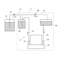
- the inkjet head 10 according to the fourth modification is connected to a circulation flow path 4 that passes through the inkjet head 10. During the ink ejection by the composite driving waveform WF, ink that is not ejected from the nozzles N circulates in the circulation flow path 4.
- FIG. 13 is a diagram showing an ink circulation flow path 4 in a head unit 3 according to the fourth modified example. 13 illustrates one head unit 3 and a main tank 51 connected to the head unit 3.
- the head unit 3 includes a first sub-tank 52, a second flow path portion 72, a liquid feed pump 62, a second sub-tank 53, a third flow path portion 73, an inkjet head 10, and a fourth flow path portion 74.
- the first sub-tank 52, the second flow path portion 72, the second sub-tank 53, the inkjet head 10, and the fourth flow path portion 74 form a circulation flow path 4.
- the main tank 51 stores ink that is supplied to the head unit 3.
- the ink in the main tank 51 is sent to the first sub-tank 52 in the head unit 3 via the first flow path section 71 by the operation of the liquid supply pump 61.
- the first sub-tank 52 is an ink tank with a smaller capacity than the main tank 51.
- the first sub-tank 52 stores ink supplied from the main tank 51.
- the first sub-tank 52 also stores ink that is returned from the outlet 15 of the inkjet head 10 via the fourth flow path section 74.
- the liquid delivery pump 62 is provided in the second flow path section 72 and delivers ink from the first sub-tank 52 to the second sub-tank 53 via the second flow path section 72.
- the second sub-tank 53 stores the ink delivered from the first sub-tank 52.
- the head difference between the second sub-tank 53 and the inkjet head 10 prevents ink from leaking from the nozzles N when not ejecting.
- the inkjet head 10 includes an inlet 14 connected to the third flow path portion 73, and an outlet 15 connected to the fourth flow path portion 74.
- Ink supplied from the second sub-tank 53 through the second flow path 73 to the inlet 14 is supplied to the nozzles N through a common flow path 121.
- Ink that is not ejected from the nozzles N is guided to the outlet 15 through the common flow path 121.
- Ink flowing out from the outlet 15 returns to the first sub-tank 52 through the fourth flow path portion 74.
- the ink circulation paths 4 for the other head units 3 are similar to those shown in FIG.
- a voltage signal of a composite drive waveform WF including a plurality of unit drive waveforms is applied to the piezoelectric element 13. This causes a plurality of ink droplets to be ejected from the nozzle N in a united state and land on the recording medium M.
- the composite drive waveform WF also includes at least four pulse waveforms within 4 AL from the start of application of the first pulse waveform.
- the composite drive waveform WF also includes a first unit drive waveform W1 and a second unit drive waveform W2 that is applied at the end of the composite drive waveform WF and ejects ink droplets at a higher speed than the first unit drive waveform W1.
- the ink also contains alcohol having a carbon number of 1 to 4 in a range of 20% by mass to 50% by mass of the entire ink.
- this driving method by applying at least four pulse waveforms within 4AL, the meniscus of the nozzle N oscillates at a high vibration frequency and the ink in the nozzle N is stirred. Therefore, even if a quick-drying ink is used, the ink in the nozzle N can be prevented from drying. Therefore, since the occurrence of destabilization of the meniscus and decap is effectively suppressed, deviations in the ink flight direction and speed can be suppressed. This makes it possible to suppress deviations in the ink landing position. In addition, it is possible to suppress the occurrence of defects in which multiple droplets land without merging. As a result, when a quick-drying ink is used, deterioration of image quality can be effectively suppressed. Therefore, it is possible to operate continuously for a long time while maintaining image quality within an acceptable range.
- the ink may also contain alcohol in a range of 20% by mass or more and 35% by mass or less based on the total mass of the ink. This ensures sufficient quick drying for practical use while suppressing the tendency for the ink to dry out. This allows the ink to be ejected in a more appropriate flight state.
- the ink may have a viscosity of 6 cP or less when it is ejected from the nozzle N. By lowering the ink viscosity in this way, the meniscus can be renewed more smoothly, making decap less likely to occur.
- the maximum width of the opening Na of the nozzle N may be 23 ⁇ m or less. This reduces the area of the meniscus, making decap less likely to occur.
- the inkjet head 10 also includes a nozzle substrate 110 having a nozzle N.
- the nozzle N penetrates the nozzle substrate 110 and has a tapered portion.
- the tapered portion has an opening area in a cross section perpendicular to the ink ejection direction that gradually increases from the opening Na side through which ink droplets are ejected toward the opposite side of the opening.
- the maximum inclination angle of the tapered portion surface from the ejection direction is 40° or more. This makes it possible to reduce the distance that the meniscus is drawn into the nozzle N in the ejection direction. By reducing the travel distance of the meniscus in this way, the meniscus can be maintained in a small area when it is drawn in. This makes it more difficult for decap to occur.
- a voltage signal with a vibration waveform W0 for vibrating the ink surface in the nozzle N may be applied to the piezoelectric element 13. This makes it possible to prevent the ink in the nozzle N from drying out when ink is not being ejected.
- the composite drive waveform WF may be applied to the piezoelectric element 13 at a frequency of 10 kHz or more. This allows the printing interval, i.e., the interval between the composite drive waveforms WF, to be shortened, making it possible to more effectively suppress the occurrence of decaps.
- the voltage amplitude of the pulse waveform included in the second unit drive waveform W2 is set to a size that causes multiple ink droplets to coalesce within 35 microseconds after application of the second unit drive waveform W2 is completed. This makes it possible to more reliably prevent the occurrence of problems caused by multiple droplets landing without coalescing. It also makes it difficult for the ink flight direction to change direction.
- the ink droplet volume after merging may be adjusted to one of a number of different droplet volumes.
- the smallest droplet volume among the multiple droplet volumes may be 5 pl or less. This allows the ink droplet volume to be easily adjusted. Also, fine dots can be formed by the impacted ink.
- the inkjet head 10 may also be connected to a circulation flow path 4 that passes through the inkjet head 10.
- ink that is not ejected from the nozzles N may be circulated in the circulation flow path 4.
- the inkjet recording device 1 includes an inkjet head 10 and a head drive control unit 20 that controls a voltage signal applied to the piezoelectric element 13.
- the head drive control unit 20 applies a voltage signal of a composite drive waveform WF including a plurality of unit drive waveforms to the piezoelectric element 13. This causes a plurality of ink droplets to be ejected from the nozzle N in a combined state and land on the recording medium M.
- the composite drive waveform WF includes at least four pulse waveforms within 4AL from the start of application of the first pulse waveform.
- the composite drive waveform WF includes a first unit drive waveform W1 and a second unit drive waveform W2 that is applied at the end of the composite drive waveform WF and ejects ink droplets at a higher speed than the first unit drive waveform W1.
- the ink contains alcohol having a carbon number of 1 to 4 in a range of 20% by mass to 50% by mass of the entire ink. This makes it possible to effectively suppress deterioration of image quality when using a quick-drying ink.
- the present invention is not limited to the above-described embodiment, and various modifications are possible.
- the number of repeat waveforms WA is not limited to two, but may be one or three or more depending on the number of ink droplets to be ejected and merged.
- each of the multiple consecutive repeating waveforms WA does not necessarily have to be completely identical, and may have shapes that are slightly different from each other.
- the number of second unit drive waveforms W2 included in the terminal waveform WB is not limited to two, but may be one or three or more.
- the entire composite drive waveform WF may be set to a potential equal to or lower than the reference potential, and the voltage amplitude ⁇ V2 of the second unit drive waveform W2 may be adjusted to be larger than the voltage amplitude ⁇ V1 of the first unit drive waveform W1.
- the vent mode inkjet head 10 is described as an example in which the ink pressure in the pressure chamber 131 is changed by deforming the piezoelectric element 13 to eject ink, but the present invention is not limited to this.
- the present invention may be applied to a shear mode inkjet head in which a pressure chamber is provided inside the piezoelectric body, and a shear mode type displacement is generated in the piezoelectric body on the wall surface of the pressure chamber to change the pressure of the ink in the pressure chamber.
- a single-pass type inkjet recording device 1 has been described as an example, but the present invention may also be applied to an inkjet recording device that records an image while scanning the inkjet head 10.
- This invention can be used in an inkjet head driving method and an inkjet recording device.
Landscapes
- Particle Formation And Scattering Control In Inkjet Printers (AREA)
Abstract
Provided are an inkjet head driving method and inkjet recording device which can effectively suppress the degradation of image quality. The inkjet head driving method has the following features. The driving method involves applying, to a piezoelectric element, a voltage signal of a complex driving waveform including a plurality of unit driving waveforms and causing a plurality of ink droplets, which are to be landed on a recording medium in a coalesced state, to be ejected from a nozzle. The complex driving waveform includes at least four pulse waveforms within 4 ALs from the application start of an initial pulse waveform. The complex driving waveform includes a first unit driving waveform and a second unit driving waveform that is applied at the end of the complex driving waveform and has a higher speed of the ejected ink droplets than the first unit driving waveform. The ink contains C1-4 alcohol in a range from 20 mass% to 50 mass% in relation to the total amount of the ink.
Description
本発明は、インクジェットヘッドの駆動方法及びインクジェット記録装置に関する。
The present invention relates to a method for driving an inkjet head and an inkjet recording device.
従来、インクジェットヘッドに設けられたノズルからインクを吐出させて所望の位置に着弾させることで画像を形成するインクジェット記録装置がある。インクジェットヘッドは、ノズルに連通する圧力室と、電圧の印加に応じて変形して圧力室内のインクに圧力変化を与える圧電素子と、を備える。所定の駆動信号を圧電素子に印加することで、圧力室内のインクの圧力変化に応じてノズルからインクが吐出される。
Conventionally, there is an inkjet recording device that forms an image by ejecting ink from nozzles provided in an inkjet head and landing it at a desired position. The inkjet head is equipped with a pressure chamber that communicates with the nozzle, and a piezoelectric element that deforms in response to the application of a voltage to cause a pressure change in the ink in the pressure chamber. By applying a specific drive signal to the piezoelectric element, ink is ejected from the nozzle in response to the pressure change of the ink in the pressure chamber.
例えば特許文献1には、複数の駆動信号の各々に応じてノズルから複数のインクの液滴を吐出させ、これらの複数のインクを合一させて記録媒体に着弾させる技術が開示されている。
For example, Patent Document 1 discloses a technology in which multiple ink droplets are ejected from a nozzle in response to multiple drive signals, and these multiple ink droplets are combined and landed on a recording medium.
しかしながら、揮発性の高い溶媒を含有した速乾性のインクを用いると、ノズル内でインクが乾燥して粘度が増大しやすくなる。このため、インクのメニスカスが不安定になったり、固化したインクによりノズルの開口部の少なくとも一部が塞がったりする。これにより、吐出される液滴ごとに飛翔方向や速度が所望の態様からずれやすくなる。この結果、複数の液滴が合一せずに、分離した状態のままで記録媒体に着弾しやすくなる。このため、画質が低下しやすくなるという課題がある。
However, when using a quick-drying ink that contains a highly volatile solvent, the ink dries inside the nozzle and the viscosity increases. This causes the ink meniscus to become unstable and at least a portion of the nozzle opening to become blocked by solidified ink. This causes the flight direction and speed of each ejected droplet to deviate from the desired state. As a result, multiple droplets tend to land on the recording medium in a separated state rather than coalescing. This poses the problem of a deterioration in image quality.
この発明の目的は、画質の低下を効果的に抑制することができるインクジェットヘッドの駆動方法及びインクジェット記録装置を提供することにある。
The object of this invention is to provide an inkjet head driving method and inkjet recording device that can effectively prevent degradation of image quality.
上記目的を達成するため、請求項1に記載のインクジェットヘッドの駆動方法の発明は、
1以上のパルス波形を含む単位駆動波形の電圧信号の印加に応じて圧電素子が変形することにより、圧力室のインクに圧力変化を与えてノズルからインクの液滴を吐出させることが可能なインクジェットヘッドの駆動方法であって、
前記圧電素子に対し、複数の前記単位駆動波形を含む複合駆動波形の電圧信号を印加して、合一した状態で記録媒体に着弾する複数のインクの液滴を前記ノズルから吐出させ、
前記複合駆動波形は、最初のパルス波形の印加開始から4AL以内に少なくとも4つのパルス波形を含み、
前記複合駆動波形は、第1の単位駆動波形と、前記複合駆動波形の最後に印加され前記第1の単位駆動波形よりも吐出されるインクの液滴の速度が大きい第2の単位駆動波形とを含み、
前記インクには、炭素数が1以上4以下のアルコールが、前記インクの全体に対して20質量%以上かつ50質量%以下の範囲で含有されている。 In order to achieve the above object, the present invention provides a method for driving an inkjet head, comprising:
A method for driving an inkjet head capable of applying a pressure change to ink in a pressure chamber and ejecting ink droplets from a nozzle by deforming a piezoelectric element in response to application of a voltage signal of a unit drive waveform including one or more pulse waveforms, comprising:
applying a voltage signal of a composite drive waveform including a plurality of the unit drive waveforms to the piezoelectric element, thereby ejecting a plurality of ink droplets from the nozzle, the ink droplets landing on a recording medium in a united state;
The composite drive waveform includes at least four pulse waveforms within 4 AL from the start of application of a first pulse waveform,
the composite drive waveform includes a first unit drive waveform and a second unit drive waveform that is applied at the end of the composite drive waveform and ejects ink droplets at a speed faster than that of the first unit drive waveform;
The ink contains an alcohol having 1 to 4 carbon atoms in an amount ranging from 20% by mass to 50% by mass based on the total mass of the ink.
請求項2に記載の発明は、請求項1に記載のインクジェットヘッドの駆動方法において、
前記インクには、前記アルコールが、前記インクの全体に対して20質量%以上かつ35質量%以下の範囲内で含有されている。 The present invention relates to a method for driving an inkjet head, comprising:
The ink contains the alcohol in an amount within the range of 20% by mass or more and 35% by mass or less based on the total mass of the ink.
前記インクには、前記アルコールが、前記インクの全体に対して20質量%以上かつ35質量%以下の範囲内で含有されている。 The present invention relates to a method for driving an inkjet head, comprising:
The ink contains the alcohol in an amount within the range of 20% by mass or more and 35% by mass or less based on the total mass of the ink.
請求項3に記載の発明は、請求項1に記載のインクジェットヘッドの駆動方法において、
前記インクは、前記ノズルから吐出される時点における粘度が6cP以下である。 The present invention relates to a method for driving an inkjet head, comprising:
The ink has a viscosity of 6 cP or less when ejected from the nozzle.
前記インクは、前記ノズルから吐出される時点における粘度が6cP以下である。 The present invention relates to a method for driving an inkjet head, comprising:
The ink has a viscosity of 6 cP or less when ejected from the nozzle.
請求項4に記載の発明は、請求項1に記載のインクジェットヘッドの駆動方法において、
前記ノズルの開口部の最大幅が23μm以下である。 The present invention as set forth inclaim 4 is the method for driving an inkjet head as set forth in claim 1, further comprising the steps of:
The maximum width of the nozzle opening is 23 μm or less.
前記ノズルの開口部の最大幅が23μm以下である。 The present invention as set forth in
The maximum width of the nozzle opening is 23 μm or less.
請求項5に記載の発明は、請求項1に記載のインクジェットヘッドの駆動方法において、
前記インクジェットヘッドは、前記ノズルを有するノズル基板を備え、
前記ノズルは、前記ノズル基板を貫通し、かつ、インクの液滴が吐出される開口部側から当該開口部の反対側に向かうに従って、インクの吐出方向に直交する断面における開口面積が漸増するテーパー部を有し、
前記開口部の中心を通り前記吐出方向に平行な断面において、前記テーパー部の面の、前記吐出方向からの傾斜角の最大値が40°以上である。 The present invention as set forth inclaim 5 is the method for driving an inkjet head as set forth in claim 1, further comprising the steps of:
the inkjet head includes a nozzle substrate having the nozzles;
the nozzle has a tapered portion that penetrates the nozzle substrate and whose opening area in a cross section perpendicular to the ink ejection direction gradually increases from an opening side through which ink droplets are ejected toward an opposite side of the opening,
In a cross section passing through the center of the opening and parallel to the discharge direction, the maximum value of the inclination angle of the surface of the tapered portion from the discharge direction is 40° or more.
前記インクジェットヘッドは、前記ノズルを有するノズル基板を備え、
前記ノズルは、前記ノズル基板を貫通し、かつ、インクの液滴が吐出される開口部側から当該開口部の反対側に向かうに従って、インクの吐出方向に直交する断面における開口面積が漸増するテーパー部を有し、
前記開口部の中心を通り前記吐出方向に平行な断面において、前記テーパー部の面の、前記吐出方向からの傾斜角の最大値が40°以上である。 The present invention as set forth in
the inkjet head includes a nozzle substrate having the nozzles;
the nozzle has a tapered portion that penetrates the nozzle substrate and whose opening area in a cross section perpendicular to the ink ejection direction gradually increases from an opening side through which ink droplets are ejected toward an opposite side of the opening,
In a cross section passing through the center of the opening and parallel to the discharge direction, the maximum value of the inclination angle of the surface of the tapered portion from the discharge direction is 40° or more.
請求項6に記載の発明は、請求項1に記載のインクジェットヘッドの駆動方法において、
前記ノズルからインクの液滴を吐出させない期間において、前記ノズルにおけるインクの液面を振動させるための振動波形の電圧信号を前記圧電素子に印加する。 The present invention as set forth in claim 6 is the method for driving an inkjet head as set forth inclaim 1, further comprising the steps of:
During a period when ink droplets are not ejected from the nozzle, a voltage signal having a vibration waveform for vibrating the ink surface in the nozzle is applied to the piezoelectric element.
前記ノズルからインクの液滴を吐出させない期間において、前記ノズルにおけるインクの液面を振動させるための振動波形の電圧信号を前記圧電素子に印加する。 The present invention as set forth in claim 6 is the method for driving an inkjet head as set forth in
During a period when ink droplets are not ejected from the nozzle, a voltage signal having a vibration waveform for vibrating the ink surface in the nozzle is applied to the piezoelectric element.
請求項7に記載の発明は、請求項1に記載のインクジェットヘッドの駆動方法において、
前記複合駆動波形を10kHz以上の周波数で前記圧電素子に印加する。 A seventh aspect of the present invention provides the inkjet head driving method according to the first aspect, further comprising the steps of:
The composite drive waveform is applied to the piezoelectric element at a frequency of 10 kHz or greater.
前記複合駆動波形を10kHz以上の周波数で前記圧電素子に印加する。 A seventh aspect of the present invention provides the inkjet head driving method according to the first aspect, further comprising the steps of:
The composite drive waveform is applied to the piezoelectric element at a frequency of 10 kHz or greater.
請求項8に記載の発明は、請求項1に記載のインクジェットヘッドの駆動方法において、
前記第2の単位駆動波形に含まれるパルス波形の電圧振幅は、前記第2の単位駆動波形の印加終了後、35マイクロ秒以内に前記複数のインクの液滴が合一する大きさに定められている。 The present invention relates to a method for driving an inkjet head, comprising:
The voltage amplitude of the pulse waveform included in the second unit drive waveform is set to a value that causes the ink droplets to coalesce within 35 microseconds after application of the second unit drive waveform is completed.
請求項9に記載の発明は、請求項1に記載のインクジェットヘッドの駆動方法において、
前記複合駆動波形に含める前記単位駆動波形の数を異ならせることで、合一後のインクの液滴量を、異なる複数の液滴量のいずれかに調整可能であり、
前記複数の液滴量のうち最小の液滴量が5pl以下である。 A ninth aspect of the present invention provides the inkjet head driving method according to the first aspect, further comprising the steps of:
the number of unit drive waveforms included in the composite drive waveform is varied, thereby making it possible to adjust the volume of the ink droplets after the ink is combined to one of a plurality of different droplet volumes;
The minimum droplet amount among the plurality of droplet amounts is 5 pl or less.
請求項10に記載の発明は、請求項1に記載のインクジェットヘッドの駆動方法において、
前記インクジェットヘッドは、当該インクジェットヘッドを通る循環流路に接続されており、
前記複合駆動波形によるインクの吐出中に、前記ノズルから吐出されなかったインクを前記循環流路において循環させる。 According to a tenth aspect of the present invention, there is provided a method for driving an inkjet head, comprising the steps of:
the inkjet head is connected to a circulation flow path passing through the inkjet head;
During the ejection of ink by the composite drive waveform, ink that has not been ejected from the nozzle is circulated in the circulation flow path.
また、上記目的を達成するため、請求項11に記載のインクジェット記録装置の発明は、
1以上のパルス波形を含む単位駆動波形の電圧信号の印加に応じて圧電素子が変形することにより、圧力室のインクに圧力変化を与えてノズルからインクの液滴を吐出させることが可能なインクジェットヘッドと、
前記圧電素子に印加する電圧信号を制御する駆動制御部と、
を備え、
前記駆動制御部は、前記圧電素子に対し、複数の前記単位駆動波形を含む複合駆動波形の電圧信号を印加して、合一した状態で記録媒体に着弾する複数のインクの液滴を前記ノズルから吐出させ、
前記複合駆動波形は、最初のパルス波形の印加開始から4AL以内に少なくとも4つのパルス波形を含み、
前記複合駆動波形は、第1の単位駆動波形と、前記複合駆動波形の最後に印加され前記第1の単位駆動波形よりも吐出されるインクの液滴の速度が大きい第2の単位駆動波形とを含み、
前記インクには、炭素数が1以上4以下のアルコールが、前記インクの全体に対して20質量%以上かつ50質量%以下の範囲で含有されている。 In order to achieve the above object, the present invention provides an ink jet recording apparatus comprising:
an inkjet head capable of applying a pressure change to ink in a pressure chamber and ejecting ink droplets from a nozzle by deforming a piezoelectric element in response to application of a voltage signal of a unit drive waveform including one or more pulse waveforms;
A drive control unit that controls a voltage signal to be applied to the piezoelectric element;
Equipped with
the drive control unit applies a voltage signal of a composite drive waveform including a plurality of the unit drive waveforms to the piezoelectric element, thereby causing a plurality of ink droplets to be ejected from the nozzle in a united state and land on a recording medium;
The composite drive waveform includes at least four pulse waveforms within 4 AL from the start of application of a first pulse waveform,
the composite drive waveform includes a first unit drive waveform and a second unit drive waveform that is applied at the end of the composite drive waveform and ejects ink droplets at a speed faster than that of the first unit drive waveform;
The ink contains an alcohol having 1 to 4 carbon atoms in an amount ranging from 20% by mass to 50% by mass based on the total mass of the ink.
本発明によれば、画質の低下を効果的に抑制することができる。
The present invention makes it possible to effectively prevent degradation of image quality.
以下、本発明のインクジェットヘッドの駆動方法及びインクジェット記録装置に係る実施の形態を図面に基づいて説明する。
Below, an embodiment of the inkjet head driving method and inkjet recording device of the present invention will be described with reference to the drawings.
(インクジェット記録装置の構成)
図1は、本発明の実施形態であるインクジェット記録装置1の概略構成を示す図である。
インクジェット記録装置1は、搬送部2と、ヘッドユニット3などを備える。
搬送部2は、2本の搬送ローラー2a、2b、及び輪状の搬送ベルト2cを備える。搬送ローラー2a、2bは、図1のX方向に延びる回転軸を中心に回転する。搬送ベルト2cは、2本の搬送ローラー2a、2bにより内側が支持されている。搬送ベルト2cは、搬送ローラー2aが図示略の搬送モーターの動作に応じて回転することで搬送ローラー2a、2bの回りを周回移動する。搬送部2は、搬送ベルト2cの搬送面上に記録媒体Mが載置された状態で搬送ベルト2cが周回移動することで、記録媒体Mを搬送ベルト2cの移動方向に搬送する。よって、搬送ベルト2cの移動方向が、記録媒体Mの搬送方向となる。搬送方向は、図1のY方向に平行である。 (Configuration of Inkjet Recording Apparatus)
FIG. 1 is a diagram showing a schematic configuration of aninkjet recording apparatus 1 according to an embodiment of the present invention.
Theinkjet recording apparatus 1 includes a transport section 2 and a head unit 3 .
Thetransport unit 2 includes two transport rollers 2a and 2b, and a ring-shaped transport belt 2c. The transport rollers 2a and 2b rotate around a rotation axis extending in the X direction of FIG. 1. The transport belt 2c is supported on the inside by the two transport rollers 2a and 2b. The transport roller 2a rotates in response to the operation of a transport motor (not shown), so that the transport belt 2c moves around the transport rollers 2a and 2b. The transport unit 2 transports the recording medium M in the moving direction of the transport belt 2c by the transport belt 2c moving around with the recording medium M placed on the transport surface of the transport belt 2c. Therefore, the moving direction of the transport belt 2c is the transport direction of the recording medium M. The transport direction is parallel to the Y direction of FIG. 1.
図1は、本発明の実施形態であるインクジェット記録装置1の概略構成を示す図である。
インクジェット記録装置1は、搬送部2と、ヘッドユニット3などを備える。
搬送部2は、2本の搬送ローラー2a、2b、及び輪状の搬送ベルト2cを備える。搬送ローラー2a、2bは、図1のX方向に延びる回転軸を中心に回転する。搬送ベルト2cは、2本の搬送ローラー2a、2bにより内側が支持されている。搬送ベルト2cは、搬送ローラー2aが図示略の搬送モーターの動作に応じて回転することで搬送ローラー2a、2bの回りを周回移動する。搬送部2は、搬送ベルト2cの搬送面上に記録媒体Mが載置された状態で搬送ベルト2cが周回移動することで、記録媒体Mを搬送ベルト2cの移動方向に搬送する。よって、搬送ベルト2cの移動方向が、記録媒体Mの搬送方向となる。搬送方向は、図1のY方向に平行である。 (Configuration of Inkjet Recording Apparatus)
FIG. 1 is a diagram showing a schematic configuration of an
The
The
なお、搬送部2の構成は図1に示したものに限られない。
例えば、搬送部2は、記録媒体Mを載置した状態でY方向に往復移動するステージを備えていてもよい。
あるいは、搬送部2は、回転する円柱状の搬送ドラムを有していてもよい。この搬送部2は、搬送ドラムが回転することで、搬送ドラムの円筒面に載置された記録媒体Mを移動させる。 The configuration of the conveyingunit 2 is not limited to that shown in FIG.
For example, thetransport unit 2 may include a stage that reciprocates in the Y direction with the recording medium M placed thereon.
Alternatively, thetransport unit 2 may have a rotating cylindrical transport drum. The transport unit 2 moves the recording medium M placed on the cylindrical surface of the transport drum by rotating the transport drum.
例えば、搬送部2は、記録媒体Mを載置した状態でY方向に往復移動するステージを備えていてもよい。
あるいは、搬送部2は、回転する円柱状の搬送ドラムを有していてもよい。この搬送部2は、搬送ドラムが回転することで、搬送ドラムの円筒面に載置された記録媒体Mを移動させる。 The configuration of the conveying
For example, the
Alternatively, the
記録媒体Mは、例えば一定の寸法に裁断された枚葉紙である。記録媒体Mは、図示略の給紙装置により搬送ベルト2c上に供給される。この記録媒体Mに対して、ヘッドユニット3からインクが吐出されることで、記録媒体Mに画像が記録される。その後、記録媒体Mは、搬送ベルト2cから所定の排紙部に排出される。なお、記録媒体Mとしては、ロール紙が用いられてもよい。また、記録媒体Mの材質は、表面に着弾したインクを定着させることが可能であれば、特に限定されない。例えば、記録媒体Mは、普通紙又は塗工紙等の紙、布帛、又はシート状の樹脂等であってもよい。
The recording medium M is, for example, a sheet of paper cut to a certain size. The recording medium M is fed onto the conveyor belt 2c by a paper feeder (not shown). An image is recorded on the recording medium M by ejecting ink from the head unit 3 onto the recording medium M. The recording medium M is then ejected from the conveyor belt 2c to a specified paper ejection section. Roll paper may also be used as the recording medium M. The material of the recording medium M is not particularly limited as long as it is possible to fix the ink that has landed on the surface. For example, the recording medium M may be paper such as plain paper or coated paper, fabric, or sheet-like resin.
ヘッドユニット3は、搬送部2により搬送される記録媒体Mに対して、画像データに基づく適切なタイミングでインクを吐出する。これにより、ヘッドユニット3は、記録媒体Mに画像を記録する。本実施形態のインクジェット記録装置1は、イエロー(Y)、マゼンタ(M)、シアン(C)、ブラック(K)の4色のインクにそれぞれ対応する4つのヘッドユニット3を備える。これらの4つのヘッドユニット3は、記録媒体Mの搬送方向上流側からY、M、C、Kの色の順に配列されている。また、ヘッドユニット3は、インクの吐出方向が鉛直方向下向きとなるように配置される。図1においては、-Z方向が鉛直方向下向きに相当する。なお、ヘッドユニット3の数は3つ以下又は5つ以上であってもよい。
The head unit 3 ejects ink at an appropriate timing based on image data onto the recording medium M being transported by the transport unit 2. In this way, the head unit 3 records an image on the recording medium M. The inkjet recording device 1 of this embodiment has four head units 3 corresponding to the four colors of ink, yellow (Y), magenta (M), cyan (C), and black (K). These four head units 3 are arranged in the order of Y, M, C, and K from the upstream side in the transport direction of the recording medium M. The head units 3 are also arranged so that the ink ejection direction is vertically downward. In FIG. 1, the -Z direction corresponds to the vertically downward direction. The number of head units 3 may be three or less, or five or more.
図2は、ヘッドユニット3の構成を示す模式図である。詳しくは、図2は、ヘッドユニット3を搬送ベルト2cの搬送面に相対する側から見た平面図である。
ヘッドユニット3は、板状の支持部3aと、複数のインクジェットヘッド10とを有する。複数のインクジェットヘッド10は、支持部3aが有する貫通孔に篏合した状態で支持部3aに固定されている。本実施形態のヘッドユニット3は、8つのインクジェットヘッド10を有する。インクジェットヘッド10は、インク吐出面が支持部3aの貫通孔から搬送ベルト2c側に向けて露出した状態で支持部3aに固定されている。インクジェットヘッド10のインク吐出面は、ノズルNの開口部を有する。 Fig. 2 is a schematic diagram showing the configuration of thehead unit 3. In detail, Fig. 2 is a plan view of the head unit 3 as viewed from the side facing the transport surface of the transport belt 2c.
Thehead unit 3 has a plate-shaped support portion 3a and a plurality of inkjet heads 10. The plurality of inkjet heads 10 are fixed to the support portion 3a in a state where they fit into through holes in the support portion 3a. The head unit 3 of this embodiment has eight inkjet heads 10. The inkjet heads 10 are fixed to the support portion 3a in a state where their ink ejection surfaces are exposed from the through holes in the support portion 3a toward the conveyor belt 2c. The ink ejection surface of the inkjet heads 10 has openings for the nozzles N.
ヘッドユニット3は、板状の支持部3aと、複数のインクジェットヘッド10とを有する。複数のインクジェットヘッド10は、支持部3aが有する貫通孔に篏合した状態で支持部3aに固定されている。本実施形態のヘッドユニット3は、8つのインクジェットヘッド10を有する。インクジェットヘッド10は、インク吐出面が支持部3aの貫通孔から搬送ベルト2c側に向けて露出した状態で支持部3aに固定されている。インクジェットヘッド10のインク吐出面は、ノズルNの開口部を有する。 Fig. 2 is a schematic diagram showing the configuration of the
The
インクジェットヘッド10が有する複数のノズルNは、X方向に等間隔に配列されている。本実施形態においては、各インクジェットヘッド10は、4つのノズル列を有する。各ノズル列は、X方向に等間隔に一次元配列されたノズルNからなる。インクジェットヘッド10が有する4つのノズル列は、ノズルNのX方向についての位置が重ならないように、X方向の位置が互いにずらされて配置されている。なお、インクジェットヘッド10が有するノズル列の数は4つに限られず、3つ以下又は5つ以上であってもよい。
The multiple nozzles N of the inkjet head 10 are arranged at equal intervals in the X direction. In this embodiment, each inkjet head 10 has four nozzle rows. Each nozzle row is made up of nozzles N arranged one-dimensionally at equal intervals in the X direction. The four nozzle rows of the inkjet head 10 are arranged with their positions in the X direction shifted from each other so that the positions of the nozzles N in the X direction do not overlap. Note that the number of nozzle rows of the inkjet head 10 is not limited to four, and may be three or less, or five or more.
ヘッドユニット3において、8つのインクジェットヘッド10は、ノズルNのX方向についての配置範囲が連続するように千鳥状に配置されている。ヘッドユニット3に含まれるノズルNのX方向についての配置範囲は、記録媒体Mのうち画像が記録可能な領域のX方向の幅をカバーしている。ヘッドユニット3は、画像の形成時には位置が固定されて用いられる。ヘッドユニット3は、記録媒体Mの搬送に応じて搬送方向についての所定間隔の各位置に対してノズルNからインクを吐出することで、シングルパス方式で画像を形成する。
In the head unit 3, the eight inkjet heads 10 are arranged in a staggered pattern so that the arrangement range of the nozzles N in the X direction is continuous. The arrangement range of the nozzles N included in the head unit 3 in the X direction covers the width in the X direction of the area of the recording medium M on which an image can be recorded. The head unit 3 is used in a fixed position when forming an image. The head unit 3 forms an image by a single pass method by ejecting ink from the nozzles N to each position at a predetermined interval in the transport direction in response to the transport of the recording medium M.
図3は、インクジェットヘッド10のインク吐出機構を示す断面図である。
インクジェットヘッド10は、ノズルNからインクを吐出させるための機構を含むヘッドチップ11を備える。以下では、+Z方向を上方、-Z方向を下方とも記す。ヘッドチップ11は、ノズルNを有するノズル基板110と、ノズルNに連通する流路を有する流路基板120と、圧電素子13等を有する素子基板130とを備える。ノズル基板110、流路基板120及び素子基板130は、この順に積層されている。ノズル基板110及び流路基板120は、接着剤等により接合されている。また、流路基板120及び素子基板130は、接着剤等により接合されている。 FIG. 3 is a cross-sectional view showing the ink ejection mechanism of the ink-jet head 10. As shown in FIG.
Theinkjet head 10 includes a head chip 11 including a mechanism for ejecting ink from nozzles N. Hereinafter, the +Z direction will also be referred to as the upward direction, and the -Z direction will also be referred to as the downward direction. The head chip 11 includes a nozzle substrate 110 having nozzles N, a flow path substrate 120 having a flow path communicating with the nozzles N, and an element substrate 130 having piezoelectric elements 13 and the like. The nozzle substrate 110, the flow path substrate 120, and the element substrate 130 are layered in this order. The nozzle substrate 110 and the flow path substrate 120 are bonded together with an adhesive or the like. The flow path substrate 120 and the element substrate 130 are also bonded together with an adhesive or the like.
インクジェットヘッド10は、ノズルNからインクを吐出させるための機構を含むヘッドチップ11を備える。以下では、+Z方向を上方、-Z方向を下方とも記す。ヘッドチップ11は、ノズルNを有するノズル基板110と、ノズルNに連通する流路を有する流路基板120と、圧電素子13等を有する素子基板130とを備える。ノズル基板110、流路基板120及び素子基板130は、この順に積層されている。ノズル基板110及び流路基板120は、接着剤等により接合されている。また、流路基板120及び素子基板130は、接着剤等により接合されている。 FIG. 3 is a cross-sectional view showing the ink ejection mechanism of the ink-
The
ノズル基板110は、複数のノズルNを有する。ノズル基板110の材質は、特には限られない。例えば、ノズル基板110の材質はシリコンであってもよい。
図4は、ノズル基板110の断面であって、ノズルNの開口部Naの中心を通りX方向に垂直な断面を示す図である。
ノズルNは、ノズル基板110を貫通している。ノズルNの-Z方向側の端部は、インクの液滴が吐出される開口部Naである。ノズルNの+Z方向側の端部は、後述する流路基板120の貫通流路123に接続される接続部Nbである。本実施形態では、開口部Naは円形である。また、接続部Nbは、円形の開口である。ノズルNは、第1ノズル流路111及び第2ノズル流路112を有する。第1ノズル流路111及び第2ノズル流路112は、Z方向に連通する。第1ノズル流路111は、開口部Naから+Z方向に延在している。第2ノズル流路112は、第1ノズル流路111の+Z方向側の端部から接続部Nbまで+Z方向に延在している。第1ノズル流路111及び第2ノズル流路112は、開口部Naの中心を通りインクの吐出方向に平行な断面において内壁面が吐出方向から傾斜しているテーパー部である。詳しくは、第1ノズル流路111及び第2ノズル流路112は、開口部Na側から接続部Nb側に向かうに従って、吐出方向に直交する断面における開口面積が漸増している。よって、開口部Naの直径dは、接続部Nbの直径よりも小さい。開口部Naの直径dは、23μm以下とすることが好ましい。開口部Naの直径dは、開口部Naの最大幅に相当する。 Thenozzle substrate 110 has a plurality of nozzles N. There is no particular limitation on the material of the nozzle substrate 110. For example, the material of the nozzle substrate 110 may be silicon.
FIG. 4 is a cross section of thenozzle substrate 110, which is a cross section passing through the center of the opening Na of the nozzle N and perpendicular to the X direction.
The nozzle N penetrates thenozzle substrate 110. The end of the nozzle N on the -Z direction side is an opening Na from which ink droplets are ejected. The end of the nozzle N on the +Z direction side is a connection portion Nb that is connected to a through flow path 123 of the flow path substrate 120 described later. In this embodiment, the opening Na is circular. The connection portion Nb is a circular opening. The nozzle N has a first nozzle flow path 111 and a second nozzle flow path 112. The first nozzle flow path 111 and the second nozzle flow path 112 communicate with each other in the Z direction. The first nozzle flow path 111 extends in the +Z direction from the opening Na. The second nozzle flow path 112 extends in the +Z direction from the end of the first nozzle flow path 111 on the +Z direction side to the connection portion Nb. The first nozzle flow path 111 and the second nozzle flow path 112 are tapered portions whose inner wall surfaces are inclined from the ejection direction in a cross section that passes through the center of the opening Na and is parallel to the ejection direction of the ink. Specifically, the opening area of the first nozzle flow path 111 and the second nozzle flow path 112 in a cross section perpendicular to the ejection direction gradually increases from the opening Na side toward the connection portion Nb side. Therefore, the diameter d of the opening Na is smaller than the diameter of the connection portion Nb. The diameter d of the opening Na is preferably 23 μm or less. The diameter d of the opening Na corresponds to the maximum width of the opening Na.
図4は、ノズル基板110の断面であって、ノズルNの開口部Naの中心を通りX方向に垂直な断面を示す図である。
ノズルNは、ノズル基板110を貫通している。ノズルNの-Z方向側の端部は、インクの液滴が吐出される開口部Naである。ノズルNの+Z方向側の端部は、後述する流路基板120の貫通流路123に接続される接続部Nbである。本実施形態では、開口部Naは円形である。また、接続部Nbは、円形の開口である。ノズルNは、第1ノズル流路111及び第2ノズル流路112を有する。第1ノズル流路111及び第2ノズル流路112は、Z方向に連通する。第1ノズル流路111は、開口部Naから+Z方向に延在している。第2ノズル流路112は、第1ノズル流路111の+Z方向側の端部から接続部Nbまで+Z方向に延在している。第1ノズル流路111及び第2ノズル流路112は、開口部Naの中心を通りインクの吐出方向に平行な断面において内壁面が吐出方向から傾斜しているテーパー部である。詳しくは、第1ノズル流路111及び第2ノズル流路112は、開口部Na側から接続部Nb側に向かうに従って、吐出方向に直交する断面における開口面積が漸増している。よって、開口部Naの直径dは、接続部Nbの直径よりも小さい。開口部Naの直径dは、23μm以下とすることが好ましい。開口部Naの直径dは、開口部Naの最大幅に相当する。 The
FIG. 4 is a cross section of the
The nozzle N penetrates the
図4の断面において、第1ノズル流路111の内壁面の、吐出方向からの傾斜角をθ1とする。また、第2ノズル流路112の内壁面の、吐出方向からの傾斜角をθ2とする。傾斜角θ1及びθ2は、θ1<θ2を満たす。傾斜角θ2は、40°以上であることが好ましい。傾斜角θ2が一定でない場合には、第2ノズル流路112の内壁面の傾斜角の最大値が40°以上であることが好ましい。本実施形態では、傾斜角θ2は50°である。また、本実施形態では、傾斜角θ1は9°である。なお、傾斜角θ1は0°であってもよい。すなわち、第1ノズル流路111は、Z方向に平行なストレート形状であってもよい。
In the cross section of FIG. 4, the inclination angle of the inner wall surface of the first nozzle flow path 111 from the discharge direction is θ1. The inclination angle of the inner wall surface of the second nozzle flow path 112 from the discharge direction is θ2. The inclination angles θ1 and θ2 satisfy θ1<θ2. It is preferable that the inclination angle θ2 is 40° or more. If the inclination angle θ2 is not constant, it is preferable that the maximum inclination angle of the inner wall surface of the second nozzle flow path 112 is 40° or more. In this embodiment, the inclination angle θ2 is 50°. Also, in this embodiment, the inclination angle θ1 is 9°. Note that the inclination angle θ1 may be 0°. In other words, the first nozzle flow path 111 may have a straight shape parallel to the Z direction.
図3に戻り、流路基板120及び素子基板130には、ノズルNに供給されるインクが通る各種流路が設けられている。詳しくは、流路基板120には、ノズルNに連通し、流路基板120をZ方向に貫通する貫通流路123が設けられている。また、素子基板130には、貫通流路123に連通する圧力室131が設けられている。また、流路基板120には、連絡流路122、及び、当該連絡流路122を介して圧力室131に連通する共通流路121が設けられている。貫通流路123、圧力室131及び連絡流路122は、ノズルNごとに設けられている。また、共通流路121は、ノズル列をなしている複数のノズルNに連通している。また、共通流路121は、ノズル列をなしている複数のノズルNの配置範囲に亘ってX方向に延在している。共通流路121に供給されたインクは、各ノズルNに対応する圧力室131及び貫通流路123を介して、複数のノズルNに供給される。
Returning to FIG. 3, the flow path substrate 120 and the element substrate 130 are provided with various flow paths through which ink supplied to the nozzles N passes. In detail, the flow path substrate 120 is provided with through flow paths 123 that communicate with the nozzles N and penetrate the flow path substrate 120 in the Z direction. The element substrate 130 is also provided with pressure chambers 131 that communicate with the through flow paths 123. The flow path substrate 120 is also provided with communication flow paths 122 and a common flow path 121 that communicates with the pressure chambers 131 via the communication flow paths 122. The through flow paths 123, the pressure chambers 131, and the communication flow paths 122 are provided for each nozzle N. The common flow path 121 is also connected to the multiple nozzles N that form the nozzle row. The common flow path 121 extends in the X direction over the arrangement range of the multiple nozzles N that form the nozzle row. The ink supplied to the common flow path 121 is supplied to the multiple nozzles N via the pressure chambers 131 and through flow paths 123 corresponding to each nozzle N.
流路基板120は、例えば、積層された複数の板状部材からなる。この複数の板状部材は、共通流路121、連絡流路122及び貫通流路123の位置に開口を有する。板状部材としては、例えばSUS(ステンレス鋼材)等の金属を用いることができる。なお、シリコン等の基板を加工することで流路基板120を形成してもよい。
The flow path substrate 120 is made of, for example, a plurality of laminated plate-like members. These plate-like members have openings at the positions of the common flow path 121, the connecting flow path 122, and the through flow path 123. For the plate-like members, for example, a metal such as SUS (stainless steel) can be used. The flow path substrate 120 may also be formed by processing a substrate such as silicon.
素子基板130は、圧力室131が形成されている圧力室層132を有する。また、素子基板130は、圧力室層132の上部に順に積層された振動板133、絶縁層134、圧電体層135及び電極層136を有する。圧力室131の下面は、圧力室層132の下面に接合された流路基板120により構成されている。圧力室131の上面は、振動板133により構成されている。振動板133は、例えば、導電性を有する金属材料からなる。振動板133は、圧電体層135の下部電極を兼ねている。下部電極は、複数の電極層136に対向する共通電極である。振動板133は、図示略の配線を介して基準電位の配線に接続されている。絶縁層134は、圧電体層135に対して振動板133を絶縁する。詳しくは、絶縁層134は、圧電機能領域R1以外の圧電体層135への電圧印加を遮蔽する。圧電体層135のうち圧電機能領域R1に相当する部分により圧電素子13が構成される。
The element substrate 130 has a pressure chamber layer 132 in which a pressure chamber 131 is formed. The element substrate 130 also has a vibration plate 133, an insulating layer 134, a piezoelectric layer 135, and an electrode layer 136, which are stacked in this order on top of the pressure chamber layer 132. The lower surface of the pressure chamber 131 is formed by the flow path substrate 120 bonded to the lower surface of the pressure chamber layer 132. The upper surface of the pressure chamber 131 is formed by the vibration plate 133. The vibration plate 133 is made of, for example, a metal material having electrical conductivity. The vibration plate 133 also serves as the lower electrode of the piezoelectric layer 135. The lower electrode is a common electrode that faces the multiple electrode layers 136. The vibration plate 133 is connected to a wiring of a reference potential via wiring not shown. The insulating layer 134 insulates the vibration plate 133 from the piezoelectric layer 135. In more detail, the insulating layer 134 blocks the application of voltage to the piezoelectric layer 135 other than the piezoelectric functional region R1. The portion of the piezoelectric layer 135 that corresponds to the piezoelectric functional region R1 constitutes the piezoelectric element 13.
圧電体層135としては、PZT(チタン酸ジルコン酸鉛)が好適である。ただし、圧電体層135としては、圧電特性を有する他の材料、例えば水晶、ニオブ酸リチウム、チタン酸バリウム、チタン酸鉛、メタニオブ酸鉛、ポリフッ化ビニリデンなどを用いてもよい。電極層136としては、例えば、貴金属を含むチタンを用いてもよい。
PZT (lead zirconate titanate) is suitable for the piezoelectric layer 135. However, other materials having piezoelectric properties, such as quartz, lithium niobate, barium titanate, lead titanate, lead metaniobate, and polyvinylidene fluoride, may also be used for the piezoelectric layer 135. For example, titanium containing a precious metal may also be used for the electrode layer 136.
圧力室層132、振動板133、絶縁層134、圧電体層135及び電極層136は、それぞれ、必ずしも単層でなくともよく、複数の層を有していてもよい。また、圧力室層132、振動板133、絶縁層134、圧電体層135及び電極層136のいずれかの層間に、さらに他の層が配置されていてもよい。
The pressure chamber layer 132, the vibration plate 133, the insulating layer 134, the piezoelectric layer 135, and the electrode layer 136 do not necessarily have to be a single layer, and may each have multiple layers. Furthermore, between any of the pressure chamber layer 132, the vibration plate 133, the insulating layer 134, the piezoelectric layer 135, and the electrode layer 136, further layers may be disposed.
このような構成のヘッドチップ11において、圧電素子13を駆動するための駆動波形の電圧信号が電極層136に供給される。本明細書では、駆動波形の電圧信号を「駆動信号」とも記す。駆動信号が供給された電極層136と、基準電位の振動板133との間に印加される電圧に応じて、圧電素子13がZ方向に撓むように変形する。この圧電素子13の変形に応じて振動板133が変形する。振動板133が変形すると、圧力室131内のインクに、変形量に応じた圧力変化が生じる。圧力室131内のインクの圧力変動に応じて、インクが圧力室131からノズルNへ押し出されたり、ノズルNなどからインクが引き戻されたりする。
In a head chip 11 configured as described above, a voltage signal with a drive waveform for driving the piezoelectric element 13 is supplied to the electrode layer 136. In this specification, the voltage signal with the drive waveform is also referred to as a "drive signal." The piezoelectric element 13 deforms so as to bend in the Z direction in response to the voltage applied between the electrode layer 136 to which the drive signal is supplied and the diaphragm 133 at a reference potential. The diaphragm 133 deforms in response to this deformation of the piezoelectric element 13. When the diaphragm 133 deforms, a pressure change occurs in the ink in the pressure chamber 131 in response to the amount of deformation. In response to the pressure fluctuation of the ink in the pressure chamber 131, ink is pushed out of the pressure chamber 131 into the nozzle N, or ink is pulled back from the nozzle N, etc.
本実施形態では、電極層136が基準電位より負の側の電位とされることで、圧電素子13は、圧力室131を膨張させる形状、すなわち、図3において上に凸となる形状に変形する。また、電極層136が基準電位より正の側の電位とされることで、圧電素子13は、圧力室131を収縮させる形状、すなわち、図3において下に凸となる形状に変形する。例えば、圧電素子13を上に凸となる形状に変形させて圧力室131を膨張させた後に、圧電素子13を元の形状に戻すと、インクに圧力が付与され、ノズルNからインクが吐出される。電極層136に印加される駆動信号の波形については、後に詳述する。
In this embodiment, when the electrode layer 136 is set to a potential more negative than the reference potential, the piezoelectric element 13 is deformed into a shape that expands the pressure chamber 131, i.e., a shape that is convex upward in FIG. 3. When the electrode layer 136 is set to a potential more positive than the reference potential, the piezoelectric element 13 is deformed into a shape that contracts the pressure chamber 131, i.e., a shape that is convex downward in FIG. 3. For example, when the piezoelectric element 13 is deformed into a shape that is convex upward to expand the pressure chamber 131, and then the piezoelectric element 13 is returned to its original shape, pressure is applied to the ink, and ink is ejected from the nozzle N. The waveform of the drive signal applied to the electrode layer 136 will be described in detail later.
図5は、インクジェット記録装置1の機能構成を示すブロック図である。
インクジェット記録装置1は、本体制御部30と、インクジェットヘッド10と、「駆動制御部」としてのヘッド駆動制御部20と、搬送制御部41と、通信部42と、操作表示部43などを備える。インクジェット記録装置1の各部は、バス44を介して信号を送受信可能に接続されている。 FIG. 5 is a block diagram showing the functional configuration of theinkjet recording apparatus 1. As shown in FIG.
Theinkjet recording device 1 includes a main body control unit 30, an inkjet head 10, a head drive control unit 20 as a "drive control unit", a transport control unit 41, a communication unit 42, an operation display unit 43, etc. The various units of the inkjet recording device 1 are connected to each other via a bus 44 so as to be able to transmit and receive signals.
インクジェット記録装置1は、本体制御部30と、インクジェットヘッド10と、「駆動制御部」としてのヘッド駆動制御部20と、搬送制御部41と、通信部42と、操作表示部43などを備える。インクジェット記録装置1の各部は、バス44を介して信号を送受信可能に接続されている。 FIG. 5 is a block diagram showing the functional configuration of the
The
本体制御部30は、インクジェット記録装置1の全体動作を統括制御する。本体制御部30は、CPU31(Central Processing Unit)と、RAM32(Random Access Memory)と、記憶部33などを備える。
The main body control unit 30 controls the overall operation of the inkjet recording device 1. The main body control unit 30 includes a CPU 31 (Central Processing Unit), a RAM 32 (Random Access Memory), a storage unit 33, etc.
CPU31は、各種演算処理を行う。CPU31は、記憶部33に記憶されている制御プログラムを読み出して、画像記録やその設定などに係る各種制御処理を行う。
The CPU 31 performs various calculation processes. The CPU 31 reads out the control programs stored in the storage unit 33 and performs various control processes related to image recording and its settings.
RAM32は、CPU31に作業用のメモリー空間を提供し、一時データを記憶する。記憶部33は、制御プログラムや設定データなどを記憶する不揮発性メモリーを含む。また、記憶部33は、通信部42を介して外部から取得されたプリントジョブに係る設定や記録対象の画像データなどを一時的に記憶するDRAMなどを備えてもよい。
RAM 32 provides working memory space for CPU 31 and stores temporary data. Storage unit 33 includes a non-volatile memory that stores control programs, setting data, etc. Storage unit 33 may also include a DRAM that temporarily stores settings related to print jobs acquired from the outside via communication unit 42, image data to be recorded, etc.
インクジェットヘッド10は、圧電素子13を含む上述したヘッドチップ11と、ヘッドチップ11の電極層136に電気的に接続された吐出選択スイッチング素子12などを備える。
吐出選択スイッチング素子12は、各圧電素子13に供給される信号を切り替える。各圧電素子13に供給される信号には、インク吐出用の駆動信号と、インク非吐出時用の駆動信号とがある。言い換えると、吐出選択スイッチング素子12は、記録対象の画像データなどに基づいて、圧電素子13に対し、圧電素子13に対応するノズルNからのインクの吐出有無に応じた駆動信号を供給する。これにより、各ノズルNにおいてインクに加えられる圧力の変動パターンが切り替えられる。インク非吐出時用の駆動信号は、インクが吐出されない程度にノズルNにおけるインクのメニスカスを振動させる、小振幅の波形(振動波形)の電圧信号である。ここで、インクのメニスカスは、ノズルNにおけるインクの液面又は界面である。 Theinkjet head 10 includes the above-mentioned head chip 11 including the piezoelectric element 13 , and the ejection selection switching element 12 electrically connected to the electrode layer 136 of the head chip 11 .
The ejectionselection switching element 12 switches the signal supplied to each piezoelectric element 13. The signals supplied to each piezoelectric element 13 include a drive signal for ejecting ink and a drive signal for non-ejection of ink. In other words, the ejection selection switching element 12 supplies a drive signal to the piezoelectric element 13 according to the presence or absence of ejection of ink from the nozzle N corresponding to the piezoelectric element 13, based on image data to be recorded. This switches the variation pattern of the pressure applied to the ink in each nozzle N. The drive signal for non-ejection of ink is a voltage signal of a small amplitude waveform (vibration waveform) that vibrates the meniscus of the ink in the nozzle N to such an extent that ink is not ejected. Here, the meniscus of the ink is the liquid surface or interface of the ink in the nozzle N.
吐出選択スイッチング素子12は、各圧電素子13に供給される信号を切り替える。各圧電素子13に供給される信号には、インク吐出用の駆動信号と、インク非吐出時用の駆動信号とがある。言い換えると、吐出選択スイッチング素子12は、記録対象の画像データなどに基づいて、圧電素子13に対し、圧電素子13に対応するノズルNからのインクの吐出有無に応じた駆動信号を供給する。これにより、各ノズルNにおいてインクに加えられる圧力の変動パターンが切り替えられる。インク非吐出時用の駆動信号は、インクが吐出されない程度にノズルNにおけるインクのメニスカスを振動させる、小振幅の波形(振動波形)の電圧信号である。ここで、インクのメニスカスは、ノズルNにおけるインクの液面又は界面である。 The
The ejection
ヘッド駆動制御部20は、記録対象画像の各画素データに応じて適切なタイミングで、インクジェットヘッド10の圧電素子13を駆動する駆動信号を出力する。ヘッド駆動制御部20は、基板上などにまとめて配置されてもよいし、インクジェット記録装置1の各部に分散して配置されていてもよい。また、ヘッド駆動制御部20の構成の一部又は全部は、インクジェットヘッド10に配置されていてもよい。ヘッド駆動制御部20は、ヘッド制御部21と、DAC22(デジタルアナログ変換器)と、駆動波形増幅回路23などを備える。
The head drive control unit 20 outputs a drive signal to drive the piezoelectric element 13 of the inkjet head 10 at an appropriate timing according to each pixel data of the image to be recorded. The head drive control units 20 may be arranged together on a substrate or the like, or may be distributed and arranged in various parts of the inkjet recording device 1. Also, some or all of the components of the head drive control unit 20 may be arranged in the inkjet head 10. The head drive control unit 20 includes a head control unit 21, a DAC 22 (digital-to-analog converter), and a drive waveform amplifier circuit 23.
ヘッド制御部21は、記録対象の画像データの有無や画像データの内容に応じてヘッド駆動制御部20の動作を制御する。ヘッド制御部21は、CPU211と、記憶部212などを備える。記憶部212には、ノズルNからインクを吐出させたりメニスカスを振動させたりするための駆動波形パターンの情報を含む波形パターンデータ212aが記憶されている。波形パターンデータ212aにおいては、駆動波形パターンがデジタル離散値配列データとして記憶されている。記憶部212としては、ROMや書き換え更新可能なフラッシュメモリーなどの不揮発性メモリーが用いられる。
The head control unit 21 controls the operation of the head drive control unit 20 depending on the presence or absence of image data to be recorded and the contents of the image data. The head control unit 21 includes a CPU 211 and a memory unit 212. The memory unit 212 stores waveform pattern data 212a including information on a drive waveform pattern for ejecting ink from the nozzle N and vibrating the meniscus. In the waveform pattern data 212a, the drive waveform pattern is stored as digital discrete value array data. The memory unit 212 can be a non-volatile memory such as a ROM or a rewritable, updatable flash memory.
CPU211は、記憶部212又は記憶部33に記憶された記録対象の画像データに基づいて、適切な波形パターンを選択してそのデータを出力する。波形パターンは、各ノズルNからインクを吐出させるか否かなどに従って、ヘッド駆動制御部20により適切な波形パターンの駆動信号が出力されるように選択される。CPU211は、波形パターンデータを、図示略のクロック信号に応じた適切なタイミングで出力する。このヘッド制御部21は、本体制御部30と共通に設けられてもよい。
The CPU 211 selects an appropriate waveform pattern based on the image data to be recorded stored in the memory unit 212 or the memory unit 33, and outputs the data. The waveform pattern is selected so that a drive signal of an appropriate waveform pattern is output by the head drive control unit 20 depending on whether or not ink is to be ejected from each nozzle N. The CPU 211 outputs the waveform pattern data at an appropriate timing according to a clock signal (not shown). This head control unit 21 may be provided in common with the main body control unit 30.
DAC22は、ヘッド制御部21から所定のクロック周波数で出力された各駆動波形の波形パターンデータをアナログ変換する。また、DAC22は、得られたアナログ信号を駆動波形増幅回路23に出力する。
The DAC 22 converts the waveform pattern data of each drive waveform output from the head control unit 21 at a predetermined clock frequency into analog form. The DAC 22 also outputs the resulting analog signal to the drive waveform amplifier circuit 23.
駆動波形増幅回路23は、DAC22から入力された信号の増幅動作を行って、各圧電素子13に対して増幅された駆動信号をそれぞれ出力する。増幅動作は、例えば、電圧増幅、及び電流増幅を含む。これにより、基準電位に対して正側及び負側に各々変化する台形状の電圧波形を含む駆動信号が、圧電素子13に対して印加される。
The drive waveform amplifier circuit 23 amplifies the signal input from the DAC 22 and outputs the amplified drive signal to each piezoelectric element 13. The amplification operation includes, for example, voltage amplification and current amplification. As a result, a drive signal including a trapezoidal voltage waveform that changes to the positive and negative sides with respect to the reference potential is applied to the piezoelectric elements 13.
搬送制御部41は、搬送ローラー2aを回転させるモーターを動作させて搬送ローラー2aを回転させる。これにより、搬送制御部41は、搬送ベルト2cにより記録媒体Mを適切なタイミング及び速度で移動させる。この搬送制御部41は、本体制御部30と共通の構成であってもよい。
The transport control unit 41 rotates the transport roller 2a by operating a motor that rotates the transport roller 2a. As a result, the transport control unit 41 moves the recording medium M at an appropriate timing and speed by the transport belt 2c. This transport control unit 41 may have a common configuration with the main body control unit 30.
通信部42は、所定の通信規格に従って外部機器とのデータの送受信を行う。通信部42は、例えば、利用する通信規格に係る接続端子、及び、通信接続に係るドライバーのハードウェア、例えばネットワークカードを備える。
The communication unit 42 transmits and receives data to and from external devices according to a specific communication standard. The communication unit 42 includes, for example, a connection terminal related to the communication standard to be used, and driver hardware related to the communication connection, such as a network card.
操作表示部43は、画像記録に係るステータス情報やメニューなどを表示する。また、操作表示部43は、ユーザーからの入力操作を受け付ける。操作表示部43は、例えば、液晶パネルによる表示画面、及び当該液晶パネルのドライバーと、液晶画面上に重ねて設けられたタッチパネルなどを備える。操作表示部43は、ユーザーによりタッチ操作がなされた位置と操作の種別に応じた操作検出信号を本体制御部30に出力する。
The operation display unit 43 displays status information and menus related to image recording. The operation display unit 43 also accepts input operations from the user. The operation display unit 43 includes, for example, a display screen made of an LCD panel, a driver for the LCD panel, and a touch panel superimposed on the LCD screen. The operation display unit 43 outputs an operation detection signal to the main body control unit 30 according to the position where the user performed a touch operation and the type of operation.
(速乾インク)
本実施形態のインクジェット記録装置1は、速乾性を有するインクをノズルNから吐出する。以下では、速乾性を有するインクを「速乾インク」と記す。
本実施形態で用いられる速乾インクは、溶剤と、当該溶剤に溶解又は分散される他の成分とを含む。ここで、他の成分は、着色剤を含み、さらに界面活性剤等を含んでいてもよい。着色剤としては、公知の顔料又は染料が用いられる。 (Quick-drying ink)
Theinkjet recording apparatus 1 of this embodiment ejects ink having quick-drying properties from the nozzles N. In the following, ink having quick-drying properties will be referred to as "quick-drying ink".
The quick-drying ink used in this embodiment contains a solvent and other components that are dissolved or dispersed in the solvent. Here, the other components include a colorant and may further include a surfactant, etc. As the colorant, a known pigment or dye is used.
本実施形態のインクジェット記録装置1は、速乾性を有するインクをノズルNから吐出する。以下では、速乾性を有するインクを「速乾インク」と記す。
本実施形態で用いられる速乾インクは、溶剤と、当該溶剤に溶解又は分散される他の成分とを含む。ここで、他の成分は、着色剤を含み、さらに界面活性剤等を含んでいてもよい。着色剤としては、公知の顔料又は染料が用いられる。 (Quick-drying ink)
The
The quick-drying ink used in this embodiment contains a solvent and other components that are dissolved or dispersed in the solvent. Here, the other components include a colorant and may further include a surfactant, etc. As the colorant, a known pigment or dye is used.
溶剤は、炭素数が1以上4以下のアルコールを含有する。また、インクの全体に対して、炭素数が1以上4以下のアルコールが20質量%以上かつ50質量%以下の範囲で含有されるように、溶剤の量、及び溶剤に占める上記アルコールの割合が調整されている。
The solvent contains an alcohol with a carbon number of 1 to 4. The amount of the solvent and the ratio of the alcohol to the solvent are adjusted so that the ink contains 20% to 50% by mass of the alcohol with a carbon number of 1 to 4.
炭素数が1以上4以下のアルコールとしては、例えば、メタノール(メチルアルコール:炭素数1)、エタノール(エチルアルコール:炭素数2)、1-プロパノール(プロピルアルコール:炭素数3)、2-プロパノール(イソプロピルアルコール:炭素数3)、1-ブタノール(ブチルアルコール:炭素数4)、2-ブタノール(sec-ブチルアルコール:炭素数4)等を用いることができる。これらの炭素数が1以上4以下のアルコールは、それ以外のアルコールに比べて低沸点で揮発性が高いため、記録媒体Mへの着弾後のインクの速乾性を効果的に高めることができる。詳しくは、インクの全体に対する炭素数が1以上4以下のアルコールの割合を20質量%以上とすることで、実用上必要とされる速乾性を確保することができる。また、インクの全体に対する炭素数が1以上4以下のアルコールの割合を50質量%以下とすることで、後述する、ノズルN内でインクが乾燥することによる問題の発生を十分に抑制することができる。速乾インクの溶剤は、炭素数1以上4以下のアルコールのみで構成するのが好ましい。この場合、2種以上の、炭素数1以上4以下のアルコールを併用してもよい。ただし、炭素数1以上4以下のアルコールと、それ以外の他のアルコールとを併用してもよい。
また、インクの全体に対して、炭素数が1以上3以下のアルコールが20質量%以上かつ50質量%以下の範囲で含有されるように調整してもよい。これにより、速乾性をより高めることができる。
また、溶剤は、水を含んでいてもよい。 Examples of alcohols having 1 to 4 carbon atoms include methanol (methyl alcohol: carbon number 1), ethanol (ethyl alcohol: carbon number 2), 1-propanol (propyl alcohol: carbon number 3), 2-propanol (isopropyl alcohol: carbon number 3), 1-butanol (butyl alcohol: carbon number 4), and 2-butanol (sec-butyl alcohol: carbon number 4). These alcohols having 1 to 4 carbon atoms have a lower boiling point and higher volatility than other alcohols, and therefore can effectively improve the quick-drying property of the ink after it lands on the recording medium M. In more detail, by setting the ratio of the alcohol having 1 to 4 carbon atoms to the entire ink to 20% by mass or more, the quick-drying property required for practical use can be ensured. In addition, by setting the ratio of the alcohol having 1 to 4 carbon atoms to the entire ink to 50% by mass or less, the occurrence of problems caused by the ink drying in the nozzle N, which will be described later, can be sufficiently suppressed. The solvent for the quick-drying ink is preferably composed only of alcohol having 1 to 4 carbon atoms. In this case, two or more types of alcohol having 1 to 4 carbon atoms may be used in combination. However, an alcohol having 1 to 4 carbon atoms may be used in combination with other alcohols.
The content of the alcohol having 1 to 3 carbon atoms may be adjusted to be in the range of 20% by mass to 50% by mass based on the entire ink, thereby making it possible to further improve the quick-drying property.
The solvent may also contain water.
また、本実施形態の速乾インクは、ノズルNから吐出される時点における粘度が6cP以下となるように調整されている。このような粘度を実現するために、インクジェット記録装置1は、インクを加熱して粘度を低下させるための加熱部を備えていてもよい。
また、本実施形態の速乾インクは、ノズルNから吐出される時点における表面張力が25mN/m以下となるように調整されている。 Furthermore, the quick-drying ink of this embodiment is adjusted so that the viscosity is 6 cP or less when it is ejected from the nozzle N. In order to achieve such a viscosity, theinkjet recording apparatus 1 may be provided with a heating unit for heating the ink to reduce the viscosity.
Furthermore, the quick-drying ink of this embodiment is adjusted so that the surface tension at the time when it is ejected from the nozzle N is 25 mN/m or less.
また、本実施形態の速乾インクは、ノズルNから吐出される時点における表面張力が25mN/m以下となるように調整されている。 Furthermore, the quick-drying ink of this embodiment is adjusted so that the viscosity is 6 cP or less when it is ejected from the nozzle N. In order to achieve such a viscosity, the
Furthermore, the quick-drying ink of this embodiment is adjusted so that the surface tension at the time when it is ejected from the nozzle N is 25 mN/m or less.
本実施形態で用いる速乾インクは、記録媒体Mへの着弾後、数百ミリ秒~数秒程度の短時間で乾燥する。従来、特にプラスチックフィルム、コート紙、又はラミネート紙等の非吸収性の記録媒体Mの表面に印刷する場合は、印刷後のインクをブローしたり加熱したりして乾燥させるのが一般的であった。これに対し、本実施形態の速乾インクを用いることで、乾燥工程を簡素化したり省略したりすることが可能となる。
一方、速乾インクは、ノズルN内においても乾燥しやすい。このため、ノズルNのメニスカスが乾燥により増粘して不安定化したり、「デキャップ」と呼ばれる現象が生じたりしやすい。ここで、デキャップは、ノズルNの開口部Na付近のインクが乾燥して増粘又は固化し、ノズルNの開口部Naの少なくとも一部が詰まる現象である。メニスカスの不安定化やデキャップが生じると、吐出される液滴の速度の低下や飛翔方向の異常による着弾位置ずれが発生する。また、複数の液滴を吐出して最終的に1つの液滴に合一させるマルチドロップ方式を採用する場合には、液滴の速度の低下や飛翔方向の異常は、液滴が適切に合一しなくなる不具合に繋がる。液滴が適切に合一しない状態で記録媒体Mに着弾すると、本来1つのドットを形成すべきインクにより複数のドットが形成されたり、ドットの形状が乱れたりする。このため、画質が劣化する。
これに対し、本実施形態のインクジェットヘッド10の駆動方法では、圧電素子13に印加する駆動信号を調整することで、メニスカスの不安定化やデキャップの発生を抑制して、画質の低下を生じにくくしている。 The quick-drying ink used in this embodiment dries in a short time of several hundred milliseconds to several seconds after landing on the recording medium M. Conventionally, particularly when printing on the surface of a non-absorbent recording medium M such as a plastic film, coated paper, or laminated paper, it has been common to dry the printed ink by blowing or heating. In contrast, by using the quick-drying ink of this embodiment, it is possible to simplify or omit the drying process.
On the other hand, quick-drying ink is also likely to dry in the nozzle N. For this reason, the meniscus of the nozzle N is likely to thicken and become unstable due to drying, or a phenomenon called "decap" may occur. Here, decap is a phenomenon in which the ink near the opening Na of the nozzle N dries and thickens or solidifies, and at least a part of the opening Na of the nozzle N is clogged. When the meniscus becomes unstable or decap occurs, the speed of the ejected droplets decreases and the landing position is shifted due to an abnormality in the flight direction. In addition, when a multi-drop method is adopted in which multiple droplets are ejected and finally merged into one droplet, the decrease in the droplet speed and the abnormality in the flight direction lead to a problem in which the droplets do not properly merge. If the droplets land on the recording medium M in a state in which they do not properly merge, multiple dots are formed by the ink that should originally form one dot, or the shape of the dot becomes distorted. This deteriorates the image quality.
In contrast, in the method of driving theinkjet head 10 of this embodiment, the drive signal applied to the piezoelectric element 13 is adjusted to suppress the occurrence of meniscus instability and decap, making it less likely that degradation of image quality will occur.
一方、速乾インクは、ノズルN内においても乾燥しやすい。このため、ノズルNのメニスカスが乾燥により増粘して不安定化したり、「デキャップ」と呼ばれる現象が生じたりしやすい。ここで、デキャップは、ノズルNの開口部Na付近のインクが乾燥して増粘又は固化し、ノズルNの開口部Naの少なくとも一部が詰まる現象である。メニスカスの不安定化やデキャップが生じると、吐出される液滴の速度の低下や飛翔方向の異常による着弾位置ずれが発生する。また、複数の液滴を吐出して最終的に1つの液滴に合一させるマルチドロップ方式を採用する場合には、液滴の速度の低下や飛翔方向の異常は、液滴が適切に合一しなくなる不具合に繋がる。液滴が適切に合一しない状態で記録媒体Mに着弾すると、本来1つのドットを形成すべきインクにより複数のドットが形成されたり、ドットの形状が乱れたりする。このため、画質が劣化する。
これに対し、本実施形態のインクジェットヘッド10の駆動方法では、圧電素子13に印加する駆動信号を調整することで、メニスカスの不安定化やデキャップの発生を抑制して、画質の低下を生じにくくしている。 The quick-drying ink used in this embodiment dries in a short time of several hundred milliseconds to several seconds after landing on the recording medium M. Conventionally, particularly when printing on the surface of a non-absorbent recording medium M such as a plastic film, coated paper, or laminated paper, it has been common to dry the printed ink by blowing or heating. In contrast, by using the quick-drying ink of this embodiment, it is possible to simplify or omit the drying process.
On the other hand, quick-drying ink is also likely to dry in the nozzle N. For this reason, the meniscus of the nozzle N is likely to thicken and become unstable due to drying, or a phenomenon called "decap" may occur. Here, decap is a phenomenon in which the ink near the opening Na of the nozzle N dries and thickens or solidifies, and at least a part of the opening Na of the nozzle N is clogged. When the meniscus becomes unstable or decap occurs, the speed of the ejected droplets decreases and the landing position is shifted due to an abnormality in the flight direction. In addition, when a multi-drop method is adopted in which multiple droplets are ejected and finally merged into one droplet, the decrease in the droplet speed and the abnormality in the flight direction lead to a problem in which the droplets do not properly merge. If the droplets land on the recording medium M in a state in which they do not properly merge, multiple dots are formed by the ink that should originally form one dot, or the shape of the dot becomes distorted. This deteriorates the image quality.
In contrast, in the method of driving the
(インクジェットヘッドの駆動方法)
以下に、本実施形態のインクジェット記録装置1におけるインクジェットヘッド10の駆動方法について説明する。
本実施形態のインクジェットヘッド10の駆動方法では、複数の単位駆動波形を含む複合駆動波形の電圧信号が用いられる。各単位駆動波形は、ノズルNから1つのインクの液滴を吐出させるための波形である。この複合駆動波形の電圧信号を電極層136に供給して圧電素子13に印加することで、ノズルNから複数のインクの液滴を吐出させることができる。また、吐出された複数のインクの液滴を、合一した状態で記録媒体Mに着弾させることができる。以下では、圧電素子13に対して駆動波形の電圧信号を印加することを、単に「駆動波形を印加する」とも記す。 (Inkjet head driving method)
A method for driving theinkjet head 10 in the inkjet recording apparatus 1 of this embodiment will be described below.
In the driving method of theinkjet head 10 of this embodiment, a voltage signal of a composite drive waveform including a plurality of unit drive waveforms is used. Each unit drive waveform is a waveform for ejecting one ink droplet from the nozzle N. By supplying this composite drive waveform voltage signal to the electrode layer 136 and applying it to the piezoelectric element 13, a plurality of ink droplets can be ejected from the nozzle N. In addition, the ejected plurality of ink droplets can be caused to land on the recording medium M in a united state. Hereinafter, applying a voltage signal of a drive waveform to the piezoelectric element 13 will also be referred to simply as "applying a drive waveform".
以下に、本実施形態のインクジェット記録装置1におけるインクジェットヘッド10の駆動方法について説明する。
本実施形態のインクジェットヘッド10の駆動方法では、複数の単位駆動波形を含む複合駆動波形の電圧信号が用いられる。各単位駆動波形は、ノズルNから1つのインクの液滴を吐出させるための波形である。この複合駆動波形の電圧信号を電極層136に供給して圧電素子13に印加することで、ノズルNから複数のインクの液滴を吐出させることができる。また、吐出された複数のインクの液滴を、合一した状態で記録媒体Mに着弾させることができる。以下では、圧電素子13に対して駆動波形の電圧信号を印加することを、単に「駆動波形を印加する」とも記す。 (Inkjet head driving method)
A method for driving the
In the driving method of the
図6は、インクジェット記録装置1におけるインク吐出用の複合駆動波形WFを示す図である。
図6の縦軸は、基準電位を0、複合駆動波形WFにおける負側の最低電位を-1としたときの電位比率を表す。基準電位は、インク吐出動作を行わない待機時の電位である。
また、横軸は時間を表す。横軸の単位は、AL(Acoustic Length)である。ALは、圧力室131内における圧力波の音響的共振周期の1/2である。ALは、通常、数マイクロ秒程度である。 FIG. 6 is a diagram showing a composite driving waveform WF for ejecting ink in theinkjet recording apparatus 1. As shown in FIG.
6 represents the potential ratio when the reference potential is 0 and the minimum negative potential in the composite drive waveform WF is -1. The reference potential is a potential during standby when no ink ejection operation is performed.
The horizontal axis represents time. The unit of the horizontal axis is AL (Acoustic Length). AL is half the acoustic resonance period of the pressure wave in thepressure chamber 131. AL is usually about several microseconds.
図6の縦軸は、基準電位を0、複合駆動波形WFにおける負側の最低電位を-1としたときの電位比率を表す。基準電位は、インク吐出動作を行わない待機時の電位である。
また、横軸は時間を表す。横軸の単位は、AL(Acoustic Length)である。ALは、圧力室131内における圧力波の音響的共振周期の1/2である。ALは、通常、数マイクロ秒程度である。 FIG. 6 is a diagram showing a composite driving waveform WF for ejecting ink in the
6 represents the potential ratio when the reference potential is 0 and the minimum negative potential in the composite drive waveform WF is -1. The reference potential is a potential during standby when no ink ejection operation is performed.
The horizontal axis represents time. The unit of the horizontal axis is AL (Acoustic Length). AL is half the acoustic resonance period of the pressure wave in the
図6の複合駆動波形WFは、ノズルNにおけるインクのメニスカスを振動させる振動波形W0と、インクの液滴を各々吐出させる4つの第1の単位駆動波形W1と、インクの液滴を各々吐出させる2つの第2の単位駆動波形W2とを含む。第2の単位駆動波形W2は、4つの第1の単位駆動波形W1の後に印加される。以下では、第1の単位駆動波形W1及び第2の単位駆動波形W2のうち任意の一方を指す場合には「単位駆動波形Wn」と記す。図6の複合駆動波形WFは、6つの単位駆動波形Wnを含む。この複合駆動波形WFを圧電素子13に印加することで、ノズルNから吐出される6つのインクの液滴を合一させて記録媒体Mに着弾させることができる。以下では、このように6つのインクの液滴を合一させたものを「大液滴」とも記す。
最初の第1の単位駆動波形W1の印加前において振動波形W0を印加してノズルNのメニスカスを振動させることで、インクのメニスカスの乾燥及び増粘によるインクの吐出特性の変動を抑制することができる。最初の第1の単位駆動波形W1の印加前の期間は、ノズルからインクの液滴を吐出させない期間の一態様である。 The composite drive waveform WF in FIG. 6 includes a vibration waveform W0 that vibrates the meniscus of the ink in the nozzle N, four first unit drive waveforms W1 that each eject an ink droplet, and two second unit drive waveforms W2 that each eject an ink droplet. The second unit drive waveform W2 is applied after the four first unit drive waveforms W1. Hereinafter, any one of the first unit drive waveforms W1 and the second unit drive waveform W2 will be referred to as a "unit drive waveform Wn". The composite drive waveform WF in FIG. 6 includes six unit drive waveforms Wn. By applying this composite drive waveform WF to thepiezoelectric element 13, six ink droplets ejected from the nozzle N can be united and landed on the recording medium M. Hereinafter, six ink droplets united in this manner will also be referred to as a "large droplet".
By applying the vibration waveform W0 before the application of the initial first unit drive waveform W1 to vibrate the meniscus of the nozzle N, it is possible to suppress fluctuations in the ink ejection characteristics due to drying and thickening of the ink meniscus. The period before the application of the initial first unit drive waveform W1 is one aspect of the period during which ink droplets are not ejected from the nozzle.
最初の第1の単位駆動波形W1の印加前において振動波形W0を印加してノズルNのメニスカスを振動させることで、インクのメニスカスの乾燥及び増粘によるインクの吐出特性の変動を抑制することができる。最初の第1の単位駆動波形W1の印加前の期間は、ノズルからインクの液滴を吐出させない期間の一態様である。 The composite drive waveform WF in FIG. 6 includes a vibration waveform W0 that vibrates the meniscus of the ink in the nozzle N, four first unit drive waveforms W1 that each eject an ink droplet, and two second unit drive waveforms W2 that each eject an ink droplet. The second unit drive waveform W2 is applied after the four first unit drive waveforms W1. Hereinafter, any one of the first unit drive waveforms W1 and the second unit drive waveform W2 will be referred to as a "unit drive waveform Wn". The composite drive waveform WF in FIG. 6 includes six unit drive waveforms Wn. By applying this composite drive waveform WF to the
By applying the vibration waveform W0 before the application of the initial first unit drive waveform W1 to vibrate the meniscus of the nozzle N, it is possible to suppress fluctuations in the ink ejection characteristics due to drying and thickening of the ink meniscus. The period before the application of the initial first unit drive waveform W1 is one aspect of the period during which ink droplets are not ejected from the nozzle.
また、図7に示すように、最初の2つの第1の単位駆動波形W1を省略することで、残りの4つの単位駆動波形により吐出された4つの液滴を合一させて記録媒体Mに着弾させることができる。このように4つのインクの液滴を合一させたインクは、「大液滴」よりも液滴量が少ない「中液滴」である。
また、図8に示すように、最初の4つの第1の単位駆動波形W1を省略することで、残りの2つの第2の単位駆動波形W2により吐出された2つの液滴を合一させて記録媒体Mに着弾させることができる。このように2つのインクの液滴を合一させたインクは、「中液滴」よりも液滴量が少ない「小液滴」である。小液滴の液滴量は、例えば5pl以下である。
このように、複合駆動波形WFに含める単位駆動波形Wnの数を異ならせることで、合一後のインクの液滴量を、異なる複数の液滴量のいずれかに調整できる。 7, by omitting the first two first unit drive waveforms W1, it is possible to combine the four droplets ejected by the remaining four unit drive waveforms and cause them to land on the recording medium M. The ink obtained by combining the four ink droplets in this way is a "medium droplet" which has a smaller droplet volume than a "large droplet."
8, by omitting the first four first unit drive waveforms W1, it is possible to combine two droplets ejected by the remaining two second unit drive waveforms W2 and have them land on the recording medium M. In this way, two ink droplets combined into one is a "small droplet" which has a smaller droplet volume than a "medium droplet." The droplet volume of a small droplet is, for example, 5 pl or less.
In this way, by varying the number of unit drive waveforms Wn included in the composite drive waveform WF, the ink droplet volume after coalescence can be adjusted to one of a number of different droplet volumes.
図6の複合駆動波形WFのうち最初の2つの第1の単位駆動波形W1により、繰り返し波形WAが構成される。また、3つ目及び4つ目の第1の単位駆動波形W1により、同様に繰り返し波形WAが構成される。これらの2つの繰り返し波形WAは、同一である。
また、複合駆動波形WFのうち最後の2つの第2の単位駆動波形W2により、終端波形WBが構成される。よって、複合駆動波形WFにおける最後の単位駆動波形は、第2の単位駆動波形W2である。 A repeat waveform WA is formed by the first two first unit driving waveforms W1 of the composite driving waveform WF in Fig. 6. Similarly, a repeat waveform WA is formed by the third and fourth first unit driving waveforms W1. These two repeat waveforms WA are identical.
Furthermore, the last two second unit drive waveforms W2 of the composite drive waveform WF constitute the terminal waveform WB. Therefore, the last unit drive waveform in the composite drive waveform WF is the second unit drive waveform W2.
このような複合駆動波形WFによれば、ノズルNから吐出されるインクの各液滴を、吐出された段階で合一した状態とすることができる。すなわち、6つの液滴が柱状に連なった状態でノズルNから吐出され、飛翔中に分離することなく記録媒体Mに着弾する。あるいは、6つの液滴が柱状に連なった状態で吐出された後、途中で分離する場合であっても、記録媒体Mへの着弾前に全ての液滴が1つに合一する。
また、複合駆動波形WFは、10kHz以上の周波数で圧電素子13に印加される。すなわち、6つの液滴が合一したインクを、100マイクロ秒以下の周期で繰り返し吐出可能である。
以下では、このような態様でのインク吐出を可能とするための、繰り返し波形WA及び終端波形WBの構成及び作用についてそれぞれ説明する。 According to such a composite drive waveform WF, each droplet of ink ejected from the nozzle N can be made to be in a united state at the stage of ejection. That is, six droplets are ejected from the nozzle N in a columnar state, and land on the recording medium M without separating during flight. Alternatively, even if six droplets are ejected in a columnar state and then separate midway, all the droplets will be united into one before landing on the recording medium M.
Moreover, the composite driving waveform WF is applied to thepiezoelectric element 13 at a frequency of 10 kHz or more. That is, six ink droplets united into one can be repeatedly ejected at a period of 100 microseconds or less.
The configurations and functions of the repeating waveform WA and the terminal waveform WB that enable ink ejection in this manner will be described below.
また、複合駆動波形WFは、10kHz以上の周波数で圧電素子13に印加される。すなわち、6つの液滴が合一したインクを、100マイクロ秒以下の周期で繰り返し吐出可能である。
以下では、このような態様でのインク吐出を可能とするための、繰り返し波形WA及び終端波形WBの構成及び作用についてそれぞれ説明する。 According to such a composite drive waveform WF, each droplet of ink ejected from the nozzle N can be made to be in a united state at the stage of ejection. That is, six droplets are ejected from the nozzle N in a columnar state, and land on the recording medium M without separating during flight. Alternatively, even if six droplets are ejected in a columnar state and then separate midway, all the droplets will be united into one before landing on the recording medium M.
Moreover, the composite driving waveform WF is applied to the
The configurations and functions of the repeating waveform WA and the terminal waveform WB that enable ink ejection in this manner will be described below.
(繰り返し波形WA)
図9は、繰り返し波形WAを拡大して示す図である。
繰り返し波形WAに含まれる2つの第1の単位駆動波形W1はそれぞれ、メインパルスP1及び引き戻しパルスP2を含む。メインパルスP1は、ノズルNからインクの液滴を吐出させるためのパルス波形である。引き戻しパルスP2は、メインパルスP1により吐出されるインクの液滴に対して吐出方向とは反対側に引き戻す方向の力を印加するためのパルス波形である。メインパルスP1及び引き戻しパルスP2の組み合わせにより1つのインクの液滴がノズルNから吐出される。メインパルスP1は「第1のパルス波形」に相当し、引き戻しパルスP2は「第2のパルス波形」に相当する。 (Repeated waveform WA)
FIG. 9 is an enlarged view of the repeating waveform WA.
Each of the two first unit drive waveforms W1 included in the repeating waveform WA includes a main pulse P1 and a pullback pulse P2. The main pulse P1 is a pulse waveform for ejecting ink droplets from the nozzle N. The pullback pulse P2 is a pulse waveform for applying a force in a direction opposite to the ejection direction to the ink droplets ejected by the main pulse P1, pulling them back. A single ink droplet is ejected from the nozzle N by a combination of the main pulse P1 and the pullback pulse P2. The main pulse P1 corresponds to a "first pulse waveform" and the pullback pulse P2 corresponds to a "second pulse waveform".
メインパルスP1は、電位が下降する膨張部分S1と、膨張部分S1の後に電位が上昇する収縮部分S2とを含む。膨張部分S1の開始時点から、膨張部分S1の終了時点までの期間を、メインパルスP1の印加期間とする。メインパルスP1のうち膨張部分S1に対応する期間においては、圧力室131が膨張するように圧電素子13が変動する。その後の収縮部分S2に対応する期間においては、圧力室131が元の形状に戻る方向に収縮するように圧電素子13が変動する。このような圧力室131の膨張及び収縮を、圧力室131内の圧力波の共振が生じるタイミングで行うことで、圧力室131内のインクに圧力が加えられてノズルNからインクが吐出される。
The main pulse P1 includes an expansion portion S1 where the potential drops, and a contraction portion S2 where the potential rises after the expansion portion S1. The period from the start of the expansion portion S1 to the end of the expansion portion S1 is the application period of the main pulse P1. During the period of the main pulse P1 corresponding to the expansion portion S1, the piezoelectric element 13 fluctuates so that the pressure chamber 131 expands. During the subsequent period corresponding to the contraction portion S2, the piezoelectric element 13 fluctuates so that the pressure chamber 131 contracts in a direction returning to its original shape. By performing such expansion and contraction of the pressure chamber 131 at a timing when resonance of the pressure wave occurs in the pressure chamber 131, pressure is applied to the ink in the pressure chamber 131 and ink is ejected from the nozzle N.
メインパルスP1における膨張部分S1の開始タイミングから収縮部分S2の開始タイミングまでの長さを、メインパルスP1のパルス幅と定義する。メインパルスP1のパルス幅は、0.7AL以上1AL以下、より好ましくは0.7AL以上0.9AL以下の範囲内で設定される。本実施形態では、2つの第1の単位駆動波形W1におけるメインパルスP1のパルス幅pw11、pw12は、いずれも0.8ALである。
The length from the start timing of the expansion portion S1 to the start timing of the contraction portion S2 in the main pulse P1 is defined as the pulse width of the main pulse P1. The pulse width of the main pulse P1 is set within the range of 0.7 AL to 1 AL, more preferably 0.7 AL to 0.9 AL. In this embodiment, the pulse widths pw11 and pw12 of the main pulse P1 in the two first unit drive waveforms W1 are both 0.8 AL.
一方、引き戻しパルスP2も、メインパルスP1と同様に膨張部分S1及び収縮部分S2を含む。膨張部分S1の開始時点から、膨張部分S1の終了時点までの期間を、引き戻しパルスP2の印加期間とする。また、引き戻しパルスP2における膨張部分S1の開始タイミングから収縮部分S2の開始タイミングまでの長さを、引き戻しパルスP2のパルス幅と定義する。引き戻しパルスP2のパルス幅は、0.3AL以上0.6AL以下であり、かつメインパルスP1のパルス波形のパルス幅より短い範囲内で設定される。本実施形態では、1つ目の第1の単位駆動波形W1における引き戻しパルスP2のパルス幅pw21は、0.4ALである。また、2つ目の第1の単位駆動波形W1における引き戻しパルスP2のパルス幅pw22は、0.5ALである。
また、パルス幅pw11とパルス幅pw21との間の待機時間wt1は、0.2ALである。パルス幅pw21とパルス幅pw12との間の待機時間wt2は、0.3ALである。パルス幅pw12とパルス幅pw22との間の待機時間wt3は、0.4ALである。 On the other hand, the pullback pulse P2 also includes an expansion portion S1 and a contraction portion S2, similar to the main pulse P1. The period from the start of the expansion portion S1 to the end of the expansion portion S1 is defined as the application period of the pullback pulse P2. The length from the start timing of the expansion portion S1 to the start timing of the contraction portion S2 in the pullback pulse P2 is defined as the pulse width of the pullback pulse P2. The pulse width of the pullback pulse P2 is set within a range of 0.3 AL to 0.6 AL, and shorter than the pulse width of the pulse waveform of the main pulse P1. In this embodiment, the pulse width pw21 of the pullback pulse P2 in the first first unit driving waveform W1 is 0.4 AL. The pulse width pw22 of the pullback pulse P2 in the second first unit driving waveform W1 is 0.5 AL.
Furthermore, the waiting time wt1 between the pulse width pw11 and the pulse width pw21 is 0.2 AL, the waiting time wt2 between the pulse width pw21 and the pulse width pw12 is 0.3 AL, and the waiting time wt3 between the pulse width pw12 and the pulse width pw22 is 0.4 AL.
メインパルスP1による残響振動を抑制するタイミングで引き戻しパルスP2の膨張部分S1を印加して圧力室131を膨張させることで、吐出されるインクの液滴を引き戻す方向に、インクの液滴に対して力を及ぼすことができる。これにより、メインパルスP1により吐出されるインクの液滴を減速させることができる。
By applying the expansion portion S1 of the pullback pulse P2 at a timing that suppresses the reverberation vibration caused by the main pulse P1 and expanding the pressure chamber 131, a force can be applied to the ink droplets in a direction that pulls back the ink droplets being ejected. This makes it possible to decelerate the ink droplets ejected by the main pulse P1.
メインパルスP1の影響で、メニスカスはノズルNの奥側に後退する。この後、引き戻しパルスP2を印加することで、吐出されるインクの液滴に対して引き戻す方向の力が印加されるとともに、後退したメニスカスをノズルNの開口部Na方向に前進させることができる。このようにメニスカスを前進させることで、次の単位駆動波形Wnにより吐出されるインクの液滴の量を増大させることができる。また、液滴量の増大に応じて当該液滴の速度を抑えることができる。メニスカスの前進により、メニスカスの位置が定常位置に近くなる。このため、高周波数でインクを吐出する場合であっても安定して所望の量及び速度の液滴を吐出することができる。
The main pulse P1 causes the meniscus to retreat toward the back of the nozzle N. Then, by applying a pullback pulse P2, a force in the pulling direction is applied to the ink droplets being ejected, and the retreated meniscus can be advanced toward the opening Na of the nozzle N. By advancing the meniscus in this way, the amount of ink droplets ejected by the next unit drive waveform Wn can be increased. Furthermore, the speed of the droplets can be reduced in accordance with the increase in the droplet amount. The advancement of the meniscus brings the position of the meniscus closer to the steady position. Therefore, even when ink is ejected at a high frequency, droplets can be ejected stably in the desired amount and speed.
繰り返し波形WAの電位は、基準電位以下の範囲内で変化する。詳しくは、繰り返し波形WAの最初のメインパルスP1は、基準電位から始まり、膨張部分S1の終了時に電圧比率-1.0まで低下する。また、繰り返し波形WAに含まれる4つのパルス波形の最低電位は、後に印加されるパルス波形ほど絶対値が小さく、基準電位に近くなる。ここで、各パルス波形の最低電位は、膨張部分S1の終了時の電位である。また、繰り返し波形WAに含まれる4つのパルス波形の印加終了時の電位は、後に印加されるパルス波形ほど絶対値が小さく、基準電位に近くなる。ここで、パルス波形の印加終了時の電位は、収縮部分S2の終了時の電位である。繰り返し波形WAの終了時点の電位は、基準電位に戻る。基準電位に戻すことで、同一の繰り返し波形WAを容易に2以上繰り返し印加することができる。
The potential of the repeating waveform WA changes within a range below the reference potential. In detail, the first main pulse P1 of the repeating waveform WA starts from the reference potential and drops to a voltage ratio of -1.0 at the end of the expansion portion S1. The minimum potential of the four pulse waveforms included in the repeating waveform WA is smaller in absolute value and closer to the reference potential for the pulse waveform that is applied later. Here, the minimum potential of each pulse waveform is the potential at the end of the expansion portion S1. The potential of the four pulse waveforms included in the repeating waveform WA is smaller in absolute value and closer to the reference potential for the pulse waveform that is applied later. Here, the potential at the end of the application of the pulse waveform is the potential at the end of the contraction portion S2. The potential at the end of the repeating waveform WA returns to the reference potential. By returning to the reference potential, the same repeating waveform WA can be easily applied repeatedly two or more times.
このような繰り返し波形WA内の電位推移により、図6に示すように、第1の単位駆動波形W1においては、引き戻しパルスP2の収縮部分S2の電圧振幅ΔV1が小さく抑えられている。これにより、引き戻しパルスP2の収縮部分S2に応じた圧力室131の収縮によるインクの加速が抑えられる。この結果、第1の単位駆動波形W1におけるメインパルスP1及び引き戻しパルスP2の組み合わせにより吐出されるインクの液滴の速度を極めて低くすることが可能となる。第1の単位駆動波形W1により吐出されるインクの液滴の速度は、例えば約1m/secである。
Due to this potential transition within the repeating waveform WA, as shown in FIG. 6, in the first unit drive waveform W1, the voltage amplitude ΔV1 of the contraction portion S2 of the pullback pulse P2 is kept small. This suppresses the acceleration of ink caused by the contraction of the pressure chamber 131 in response to the contraction portion S2 of the pullback pulse P2. As a result, it is possible to extremely slow down the speed of ink droplets ejected by the combination of the main pulse P1 and the pullback pulse P2 in the first unit drive waveform W1. The speed of ink droplets ejected by the first unit drive waveform W1 is, for example, approximately 1 m/sec.
繰り返し波形WAは、全体の長さが3.5AL以上4.5AL未満の範囲内となるように、より好ましくは4ALに近くなるように、波形が調整される。本実施形態では、繰り返し波形WAの長さは4ALである。これにより、前段の繰り返し波形WAの終了時におけるノズルN内の圧力波が、後段の繰り返し波形WAにより吐出されるインクを加速する状態となる。このため、後段の繰り返し波形WAにより吐出されるインクの液滴速度が低過ぎて合一できなくなる不具合の発生を抑制することができる。
なお、繰り返し波形WAの長さが上記条件を満たしていれば、繰り返し波形WAに含まれる各第1の単位駆動波形W1の長さは均等でなくてもよい。 The repeating waveform WA is adjusted so that the overall length is within a range of 3.5 AL or more and less than 4.5 AL, and more preferably close to 4 AL. In this embodiment, the length of the repeating waveform WA is 4 AL. This causes the pressure wave in the nozzle N at the end of the first repeating waveform WA to accelerate the ink ejected by the second repeating waveform WA. This makes it possible to suppress the occurrence of a problem in which the ink droplet speed ejected by the second repeating waveform WA is too slow to coalesce.
As long as the length of the repetitive waveform WA satisfies the above condition, the lengths of the first unit driving waveforms W1 included in the repetitive waveform WA do not need to be uniform.
また、複合駆動波形WFは、最初のパルス波形の印加開始から4AL以内に少なくとも4つのパルス波形の印加期間を含むことが好ましい。言い換えると、複合駆動波形WFの先頭には、最初のパルス波形の印加開始から4AL以内の期間において、平均して1AL当たりに1パルス以上の頻度でパルス波形が印加されることが好ましい。ここで、4AL以内に印加されるパルス波形は、メインパルスP1又は引き戻しパルスP2を指し、振動波形W0は含まない。本実施形態では、図9に示すように、複合駆動波形WFの最初の繰り返し波形WAは4AL以内に4つのパルス波形の印加期間を含む。4AL以内に少なくとも4つのパルス波形を印加することで、ノズルNのメニスカスが高い振動数で揺動するとともにノズルN内のインクが攪拌される。このため、メニスカスの不安定化やデキャップを効果的に抑制することができる。この結果、最初に吐出される液滴の曲がりを抑制することができる。
Furthermore, it is preferable that the composite drive waveform WF includes an application period of at least four pulse waveforms within 4 AL from the start of application of the first pulse waveform. In other words, it is preferable that a pulse waveform is applied to the beginning of the composite drive waveform WF at a frequency of at least one pulse per AL on average during the period within 4 AL from the start of application of the first pulse waveform. Here, the pulse waveform applied within 4 AL refers to the main pulse P1 or the pullback pulse P2, and does not include the vibration waveform W0. In this embodiment, as shown in FIG. 9, the first repeat waveform WA of the composite drive waveform WF includes an application period of four pulse waveforms within 4 AL. By applying at least four pulse waveforms within 4 AL, the meniscus of the nozzle N oscillates at a high vibration frequency and the ink in the nozzle N is agitated. Therefore, it is possible to effectively suppress instability and decap of the meniscus. As a result, it is possible to suppress bending of the first droplet to be ejected.
図10は、第1の単位駆動波形W1により吐出されるインクの挙動を説明する図である。
図10の左側には、本実施形態の第1の単位駆動波形W1により吐出されるインクの挙動が描かれている。図10の右側には、比較例の単位駆動波形により吐出されるインクの挙動が描かれている。比較例の単位駆動波形は、メインパルスP1を含み、引き戻しパルスP2を含まない点で本実施形態の第1の単位駆動波形W1と異なる。 FIG. 10 is a diagram for explaining the behavior of ink ejected by the first unit drive waveform W1.
The behavior of ink ejected by the first unit drive waveform W1 of this embodiment is depicted on the left side of Fig. 10. The behavior of ink ejected by a unit drive waveform of a comparative example is depicted on the right side of Fig. 10. The unit drive waveform of the comparative example differs from the first unit drive waveform W1 of this embodiment in that it includes a main pulse P1 but does not include a pullback pulse P2.
図10の上段には、最初の単位駆動波形に応じてノズルNから1つ目のインクの液滴D1が吐出されているタイミングT1の様子が描かれている。
本実施形態では、タイミングT1において、引き戻しパルスP2の印加に応じて、吐出されたインクの液滴D1がノズルN側に引き戻されている。よって、比較例と比較して、液滴D1の位置がノズルNの開口部に近い。
また、本実施形態では、液滴D1に対してノズルN側に引き戻す方向の力が印加されたことに伴ってメニスカスmが吐出方向に前進している。これにより、本実施形態のメニスカスmの位置は、比較例のメニスカスmの位置よりノズルNの開口部に近い。 The upper part of FIG. 10 illustrates a state at timing T1 when the first ink droplet D1 is ejected from the nozzle N in response to the first unit drive waveform.
In this embodiment, at timing T1, in response to the application of the pullback pulse P2, the ejected ink droplet D1 is pulled back toward the nozzle N. Therefore, the position of the droplet D1 is closer to the opening of the nozzle N than in the comparative example.
Furthermore, in this embodiment, the meniscus m advances in the ejection direction as a result of the application of a force to the droplet D1 in a direction pulling it back toward the nozzle N. As a result, the position of the meniscus m in this embodiment is closer to the opening of the nozzle N than the position of the meniscus m in the comparative example.
図10の下段には、2つ目の単位駆動波形のメインパルスP1に応じてノズルNから2つ目のインクの液滴D2が吐出されているタイミングT2の様子が描かれている。
本実施形態では、タイミングT2において吐出される液滴D2の速度が低く抑えられている。これは、タイミングT1で引き戻しパルスP2によりメニスカスmが前進した結果、2つ目の液滴D2の量が多くなり、これに応じて速度が低くなるためである。本実施形態では、このように液滴D1、D2がいずれも低速で吐出されるため、液滴D1、D2が連なって合一した状態でノズルNから吐出される。同様に、3つ目及び4つ目の第1の単位駆動波形W1により吐出されるインクも同様に低速となる。このため、3つ目及び4つ目のインクの液滴も、前段で吐出されている液滴D1、D2に連なって合一した状態で吐出される。 The lower part of FIG. 10 illustrates a state at timing T2 when a second ink droplet D2 is ejected from nozzle N in response to main pulse P1 of the second unit drive waveform.
In this embodiment, the speed of the droplet D2 ejected at timing T2 is kept low. This is because the amount of the second droplet D2 increases as a result of the meniscus m moving forward due to the pullback pulse P2 at timing T1, and the speed decreases accordingly. In this embodiment, since both the droplets D1 and D2 are ejected at low speed in this manner, the droplets D1 and D2 are ejected from the nozzle N in a continuous and merged state. Similarly, the ink ejected by the third and fourth first unit drive waveforms W1 is also ejected at low speed. Therefore, the third and fourth ink droplets are also ejected in a continuous and merged state with the droplets D1 and D2 ejected in the previous stage.
一方、比較例では、2つ目のインクの液滴D2の速度が本実施形態より大きく、タイミングT2の時点で本実施形態より遠方まで飛翔している。これは、比較例では液滴D2の量が本実施形態よりも少ないので、これに応じて2つ目の液滴の速度が大きくなるためである。液滴D2の量が少なくなる理由は、引き戻しパルスP2が印加されないことによって、メニスカスmが後退した状態で2つ目のインクの液滴D2が吐出されるためである。このように、比較例では、液滴D1、D2がいずれも本実施形態より高速で飛翔する。このため、図10の段階では液滴D1、D2が連なっているものの、時間の経過とともに液滴D1、D2が分離しやすく、記録媒体M上の着弾位置がずれやすい。
On the other hand, in the comparative example, the speed of the second ink droplet D2 is faster than in this embodiment, and it flies farther at timing T2 than in this embodiment. This is because the amount of droplet D2 in the comparative example is smaller than in this embodiment, and the speed of the second droplet is correspondingly greater. The reason for the smaller amount of droplet D2 is that the second ink droplet D2 is ejected with the meniscus m retracted due to the absence of the application of the pullback pulse P2. In this way, in the comparative example, both droplets D1 and D2 fly faster than in this embodiment. For this reason, although droplets D1 and D2 are connected together at the stage in FIG. 10, droplets D1 and D2 tend to separate over time, and the landing position on the recording medium M tends to shift.
(終端波形WB)
図11は、終端波形WBを拡大して示す図である。
終端波形WBに含まれる2つの第2の単位駆動波形W2は、それぞれ、第1の単位駆動波形W1と同様に、メインパルスP1及び引き戻しパルスP2を含む。第2の単位駆動波形W2のメインパルスP1及び引き戻しパルスP2も、それぞれ膨張部分S1及び収縮部分S2を含む。第2の単位駆動波形W2においても、メインパルスP1及び引き戻しパルスP2の組み合わせにより1つのインクの液滴がノズルNから吐出される。 (Terminal waveform WB)
FIG. 11 is an enlarged view of the terminal waveform WB.
The two second unit drive waveforms W2 included in the terminal waveform WB each include a main pulse P1 and a pullback pulse P2, similar to the first unit drive waveform W1. The main pulse P1 and the pullback pulse P2 of the second unit drive waveform W2 also include an expansion portion S1 and a contraction portion S2. In the second unit drive waveform W2 as well, a single ink droplet is ejected from the nozzle N by a combination of the main pulse P1 and the pullback pulse P2.
第2の単位駆動波形W2におけるメインパルスP1のパルス幅も、第1の単位駆動波形W1と同様、0.7AL以上1AL以下、より好ましくは0.7AL以上0.9AL以下の範囲内で設定される。さらに、第2の単位駆動波形W2におけるメインパルスP1のパルス幅は、第1の単位駆動波形W1におけるメインパルスP1のパルス幅以上となるように定められている。本実施形態では、1つ目の第2の単位駆動波形W2におけるメインパルスP1のパルス幅pw13は、0.8ALである。また、2つ目の第2の単位駆動波形W2におけるメインパルスP1のパルス幅pw14は、0.9ALである。
なお、各第2の単位駆動波形W2におけるメインパルスP1のパルス幅を、第1の単位駆動波形W1におけるメインパルスP1のパルス幅のいずれよりも大きくしてもよい。 The pulse width of the main pulse P1 in the second unit drive waveform W2 is set within the range of 0.7 AL to 1 AL, more preferably 0.7 AL to 0.9 AL, similar to the first unit drive waveform W1. Furthermore, the pulse width of the main pulse P1 in the second unit drive waveform W2 is set to be equal to or greater than the pulse width of the main pulse P1 in the first unit drive waveform W1. In this embodiment, the pulse width pw13 of the main pulse P1 in the first second unit drive waveform W2 is 0.8 AL. Moreover, the pulse width pw14 of the main pulse P1 in the second unit drive waveform W2 is 0.9 AL.
The pulse width of the main pulse P1 in each second unit driving waveform W2 may be greater than any of the pulse widths of the main pulse P1 in the first unit driving waveform W1.
また、1つ目の第2の単位駆動波形W2における引き戻しパルスP2のパルス幅pw23は、0.5ALである。また、2つ目の第2の単位駆動波形W2における引き戻しパルスP2のパルス幅pw24は、0.4ALである。
また、パルス幅pw13とパルス幅pw23との間の待機時間wt4は、0.5ALである。また、パルス幅pw23とパルス幅pw14との間の待機時間wt5は、0.6ALである。また、パルス幅pw14とパルス幅pw24との間の待機時間wt6は、0.5ALである。終端波形WBにおける各待機時間wt4~wt6は、繰り返し波形WAにおける待機時間wt1~wt3のいずれよりも長い。 The pulse width pw23 of the pullback pulse P2 in the first second unit drive waveform W2 is 0.5 AL, and the pulse width pw24 of the pullback pulse P2 in the second second unit drive waveform W2 is 0.4 AL.
Furthermore, the wait time wt4 between the pulse width pw13 and the pulse width pw23 is 0.5 AL. The wait time wt5 between the pulse width pw23 and the pulse width pw14 is 0.6 AL. The wait time wt6 between the pulse width pw14 and the pulse width pw24 is 0.5 AL. Each of the wait times wt4 to wt6 in the terminal waveform WB is longer than any of the wait times wt1 to wt3 in the repeating waveform WA.
図6に示すように、第2の単位駆動波形W2における引き戻しパルスP2の収縮部分S2の電圧振幅ΔV2は、第1の単位駆動波形W1における引き戻しパルスP2の収縮部分S2の電圧振幅ΔV1より大きい。具体的には、ΔV1が0.73であるのに対し、ΔV2は1.1である。
このような電圧振幅ΔV2を確保するために、第2の単位駆動波形W2においては、引き戻しパルスP2の一部が基準電位より高くなっている。詳しくは、引き戻しパルスP2のうち収縮部分S2が、基準電位を超える電位まで変位する。 6, the voltage amplitude ΔV2 of the contraction portion S2 of the pullback pulse P2 in the second unit drive waveform W2 is larger than the voltage amplitude ΔV1 of the contraction portion S2 of the pullback pulse P2 in the first unit drive waveform W1. Specifically, ΔV1 is 0.73, while ΔV2 is 1.1.
In order to ensure such a voltage amplitude ΔV2, a part of the pullback pulse P2 in the second unit drive waveform W2 is made higher than the reference potential. More specifically, the contracting portion S2 of the pullback pulse P2 is displaced to a potential exceeding the reference potential.
このように電圧振幅ΔV2を大きくすることで、メインパルスP1により吐出されるインクが、引き戻しパルスP2の収縮部分S2に応じた圧力室131の収縮により大きく加速される。よって、第2の単位駆動波形W2により吐出されるインクの液滴の速度を高めることができる。この結果、第2の単位駆動波形W2により吐出されるインクは、第1の単位駆動波形W1によって先に吐出されているインクの液滴に追い付きやすい。電圧振幅ΔV2は、第2の単位駆動波形W2の印加終了後、35マイクロ秒以内に6つのインクの液滴が合一する大きさに定められている。第2の単位駆動波形W2により吐出されるインクの液滴の速度は、例えば約7m/secである。
By increasing the voltage amplitude ΔV2 in this way, the ink ejected by the main pulse P1 is greatly accelerated by the contraction of the pressure chamber 131 in response to the contraction portion S2 of the pullback pulse P2. This increases the speed of the ink droplets ejected by the second unit drive waveform W2. As a result, the ink ejected by the second unit drive waveform W2 easily catches up with the ink droplets that have been ejected earlier by the first unit drive waveform W1. The voltage amplitude ΔV2 is set to a size that causes six ink droplets to coalesce within 35 microseconds after the application of the second unit drive waveform W2 is completed. The speed of the ink droplets ejected by the second unit drive waveform W2 is, for example, approximately 7 m/sec.
終端波形WBに含まれる最後の引き戻しパルスP2の印加終了後には、電位が基準電位よりも高いキャンセル波形が印加される。キャンセル波形のパルス幅pw3の長さは、ALである。引き戻しパルスP2の後にこのようなキャンセル波形を印加することで、AL周期で揺動しているノズルN内の圧力振動をキャンセルすることができる。これにより、次の複合駆動波形WFの印加時におけるノズルN内の圧力振動を抑えて、適切な量及び速度のインクの液滴を吐出することができる。
After the application of the final pullback pulse P2 included in the terminal waveform WB has been completed, a cancel waveform with a potential higher than the reference potential is applied. The length of the pulse width pw3 of the cancel waveform is AL. By applying such a cancel waveform after the pullback pulse P2, it is possible to cancel the pressure vibrations in the nozzle N that oscillate with an AL period. This makes it possible to suppress the pressure vibrations in the nozzle N when the next composite drive waveform WF is applied, and to eject ink droplets of an appropriate amount and speed.
(実施例)
次に、上記実施形態の駆動方法の効果を確認するために行った実験について説明する。
図12は、実験の内容及び結果を示す図である。
実験では、エタノールを含有する溶媒を含むインクを用いた。また、上述の複合駆動波形WFによりインクジェットヘッド10のノズルNからインクを吐出させた。そして、吐出されたインクの飛翔状態、及びノズルNのデキャップの程度について評価を行った。
また、エタノールの含有率(重量%)が異なる3つのインクのサンプル(No.1~No.3)で実験を行った。インク全体におけるエタノールの含有率は、サンプルNo.1が35質量%、サンプルNo.2が50質量%、サンプルNo.3が65質量%である。
飛翔状態は、「A」~「C」の3段階で評価した。詳しくは、インクの液滴の飛翔方向及び速度に乱れが検出されなかった場合を「A」とした。また、許容可能な画質の範囲内で、一部のノズルNからのインクの液滴の飛翔方向及び/又は速度に乱れが検出された場合を「B」とした。また、多数のノズルNからのインクの液滴の飛翔方向及び/又は速度に乱れが検出された結果、許容不可能な画質の低下が生じた場合を「C」とした。
デキャップは、「A」~「C」の3段階で評価した。詳しくは、デキャップが生じず各ノズルNから適正にインクの液滴が吐出された場合を「A」とした。また、許容可能な画質の範囲内で、一部のノズルNでデキャップが生じてインクが不吐出となった場合を「B」とした。また、多数のノズルNでデキャップが生じてインクが不吐出となった結果、許容不可能な画質の低下が生じた場合を「C」とした。 (Example)
Next, an experiment conducted to confirm the effect of the driving method of the above embodiment will be described.
FIG. 12 is a diagram showing the details and results of the experiment.
In the experiment, ink containing a solvent containing ethanol was used. In addition, ink was ejected from the nozzle N of theinkjet head 10 by the above-mentioned composite driving waveform WF. Then, the flight state of the ejected ink and the degree of decap of the nozzle N were evaluated.
In addition, experiments were conducted with three ink samples (No. 1 to No. 3) with different ethanol contents (wt%). The ethanol contents in the entire ink were 35% by mass for Sample No. 1, 50% by mass for Sample No. 2, and 65% by mass for Sample No. 3.
The flight state was evaluated on a three-level scale from "A" to "C." More specifically, a case where no disturbance was detected in the flight direction and speed of the ink droplets was rated "A." A case where disturbance was detected in the flight direction and/or speed of the ink droplets from some nozzles N within the range of acceptable image quality was rated "B." A case where disturbance was detected in the flight direction and/or speed of the ink droplets from many nozzles N, resulting in an unacceptable degradation in image quality was rated "C."
Decap was evaluated on a three-level scale from "A" to "C." Specifically, a case in which decap did not occur and ink droplets were properly ejected from each nozzle N was rated "A." A case in which decap occurred in some nozzles N and ink did not eject within the range of acceptable image quality was rated "B." A case in which decap occurred in many nozzles N and ink did not eject, resulting in an unacceptable degradation in image quality was rated "C."
次に、上記実施形態の駆動方法の効果を確認するために行った実験について説明する。
図12は、実験の内容及び結果を示す図である。
実験では、エタノールを含有する溶媒を含むインクを用いた。また、上述の複合駆動波形WFによりインクジェットヘッド10のノズルNからインクを吐出させた。そして、吐出されたインクの飛翔状態、及びノズルNのデキャップの程度について評価を行った。
また、エタノールの含有率(重量%)が異なる3つのインクのサンプル(No.1~No.3)で実験を行った。インク全体におけるエタノールの含有率は、サンプルNo.1が35質量%、サンプルNo.2が50質量%、サンプルNo.3が65質量%である。
飛翔状態は、「A」~「C」の3段階で評価した。詳しくは、インクの液滴の飛翔方向及び速度に乱れが検出されなかった場合を「A」とした。また、許容可能な画質の範囲内で、一部のノズルNからのインクの液滴の飛翔方向及び/又は速度に乱れが検出された場合を「B」とした。また、多数のノズルNからのインクの液滴の飛翔方向及び/又は速度に乱れが検出された結果、許容不可能な画質の低下が生じた場合を「C」とした。
デキャップは、「A」~「C」の3段階で評価した。詳しくは、デキャップが生じず各ノズルNから適正にインクの液滴が吐出された場合を「A」とした。また、許容可能な画質の範囲内で、一部のノズルNでデキャップが生じてインクが不吐出となった場合を「B」とした。また、多数のノズルNでデキャップが生じてインクが不吐出となった結果、許容不可能な画質の低下が生じた場合を「C」とした。 (Example)
Next, an experiment conducted to confirm the effect of the driving method of the above embodiment will be described.
FIG. 12 is a diagram showing the details and results of the experiment.
In the experiment, ink containing a solvent containing ethanol was used. In addition, ink was ejected from the nozzle N of the
In addition, experiments were conducted with three ink samples (No. 1 to No. 3) with different ethanol contents (wt%). The ethanol contents in the entire ink were 35% by mass for Sample No. 1, 50% by mass for Sample No. 2, and 65% by mass for Sample No. 3.
The flight state was evaluated on a three-level scale from "A" to "C." More specifically, a case where no disturbance was detected in the flight direction and speed of the ink droplets was rated "A." A case where disturbance was detected in the flight direction and/or speed of the ink droplets from some nozzles N within the range of acceptable image quality was rated "B." A case where disturbance was detected in the flight direction and/or speed of the ink droplets from many nozzles N, resulting in an unacceptable degradation in image quality was rated "C."
Decap was evaluated on a three-level scale from "A" to "C." Specifically, a case in which decap did not occur and ink droplets were properly ejected from each nozzle N was rated "A." A case in which decap occurred in some nozzles N and ink did not eject within the range of acceptable image quality was rated "B." A case in which decap occurred in many nozzles N and ink did not eject, resulting in an unacceptable degradation in image quality was rated "C."
実験の結果、エタノール比率が35質量%であるサンプルNo.1は、飛翔状態及びデキャップの評価結果がいずれも「A」となった。これは、先頭から4AL以内の4つのパルス波形によってノズルN内のインクが効果的に攪拌された結果、メニスカスの不安定化やデキャップの発生が抑制されたためである。また、4つの低速の液滴が吐出された後に、2つの高速の液滴が吐出されることで、6つの液滴が好適に合一し、分離することなく着弾したためである。
また、エタノール比率が50質量%であるサンプルNo.2は、飛翔状態の評価結果が「B」、デキャップの評価結果が「A」となった。サンプルNo.2のインクは、サンプルNo.1よりもエタノール比率が高い。このため、ノズルN内でインクが乾燥しやすく、開口部Naの一部を塞ぐようにインクが固化しやすい。この影響により飛翔状態に若干乱れが生じやすく、評価結果が「B」となったものの、許容可能な画質が得られた。
一方、エタノール比率が65質量%であるサンプルNo.3は、飛翔状態及びデキャップの評価結果がいずれも「C」となった。これは、エタノール比率が過剰に高いことによってノズルN内でインクが極度に乾燥しやすいためである。 As a result of the experiment, the flying condition and decap evaluation results of sample No. 1, which has an ethanol ratio of 35% by mass, were both "A". This is because the ink in the nozzle N was effectively stirred by the four pulse waveforms within 4AL from the beginning, suppressing the destabilization of the meniscus and the occurrence of decap. In addition, the six droplets were appropriately united and landed without separation by ejecting two high-speed droplets after ejecting four low-speed droplets.
Sample No. 2, which has an ethanol ratio of 50% by mass, received a flying condition evaluation result of "B" and a decap evaluation result of "A." The ink of Sample No. 2 has a higher ethanol ratio than Sample No. 1. This makes the ink dry easily in the nozzle N and solidify so as to block part of the opening Na. This tends to cause some disturbance in the flying condition, resulting in a rating of "B," but an acceptable image quality was obtained.
On the other hand, sample No. 3, which has an ethanol ratio of 65% by mass, received a rating of "C" in both the flying state and decap evaluation results. This is because the ink in the nozzle N is extremely prone to drying due to the excessively high ethanol ratio.
図12の実験結果から、以下のことが導かれる。インクの全体におけるエタノールの含有率を50質量%以下とし、上述の複合駆動波形WFを用いることで、インクを適正な飛翔状態で吐出させることができる。さらに、インクの全体におけるエタノールの含有率を35質量%以下とし、上述の複合駆動波形WFを用いることで、インクをより適正な飛翔状態で吐出させることができる。
なお、炭素数が1以上4以下のアルコールのうちエタノール以外のアルコールを用いた場合も、図12と同様の結果が得られた。 The experimental results in Fig. 12 lead to the following. By setting the ethanol content in the entire ink to 50% by mass or less and using the above-mentioned composite driving waveform WF, it is possible to eject the ink in an appropriate flying state. Furthermore, by setting the ethanol content in the entire ink to 35% by mass or less and using the above-mentioned composite driving waveform WF, it is possible to eject the ink in an even more appropriate flying state.
In addition, when an alcohol other than ethanol among alcohols having 1 to 4 carbon atoms was used, the same results as those shown in FIG. 12 were obtained.
(変形例1)
次に、上記実施形態の変形例1について説明する。
上記実施形態の複合駆動波形WFは、最初のパルス波形の印加開始から4AL以内に4つのパルス波形を含むが、これに代えて、最初のパルス波形の印加開始から4AL以内に5つ以上のパルス波形を含んでいてもよい。例えば、長さが4ALである最初の繰り返し波形WAに3つの第1の単位駆動波形W1を含ませて、当該繰り返し波形WAにより3つの液滴が吐出されるようにしてもよい。この態様では、最初のパルス波形の印加開始から4AL以内に6つのパルス波形、すなわち3つのメインパルスP1及び3つの引き戻しパルスP2の印加期間が含まれる。これによれば、ノズルNのメニスカスをより高い振動数で揺動させて効果的にノズルN内のインクを攪拌することができる。このため、メニスカスの不安定化やデキャップをより効果的に抑制することができる。 (Variation 1)
Next, a first modification of the above embodiment will be described.
The composite driving waveform WF in the above embodiment includes four pulse waveforms within 4AL from the start of application of the first pulse waveform, but instead, it may include five or more pulse waveforms within 4AL from the start of application of the first pulse waveform. For example, three first unit driving waveforms W1 may be included in the first repeating waveform WA having a length of 4AL, so that three droplets are ejected by the repeating waveform WA. In this aspect, six pulse waveforms, that is, the application periods of three main pulses P1 and three pullback pulses P2, are included within 4AL from the start of application of the first pulse waveform. This makes it possible to effectively agitate the ink in the nozzle N by oscillating the meniscus of the nozzle N at a higher vibration frequency. Therefore, it is possible to more effectively suppress the instability and decap of the meniscus.
(変形例2)
次に、上記実施形態の変形例2について説明する。変形例2は、変形例1と組み合わせてもよい。
以下では、インクの全体における炭素数が1以上4以下のアルコールの含有率を「含有率R(重量%)」とする。また、最初のパルス波形の印加開始から4AL以内に印加するパルス波形の数を「パルス数PN」とする。本変形例では、含有率Rが大きいほどパルス数PNが多くなるように、複合駆動波形WFの駆動波形パターンが定められる。
含有率Rが大きいほど、ノズルN内においてインクが乾燥しやすい。また、パルス数PNが多いほど、ノズルNのメニスカスの振動頻度が高くなり、インクの乾燥抑制効果が高まる。よって、本変形例の駆動方法によれば、ノズルN内においてインクが乾燥しやすい場合ほど、インクの乾燥抑制効果を高めることができる。このため、速乾インクの組成に応じて適切に、メニスカスの不安定化やデキャップを抑制することができる。 (Variation 2)
Next, a second modification of the above embodiment will be described. The second modification may be combined with the first modification.
In the following, the content of alcohol having a carbon number of 1 to 4 in the entire ink is referred to as "content R (wt %)". Also, the number of pulse waveforms applied within 4 AL from the start of application of the first pulse waveform is referred to as "pulse number PN". In this modified example, the drive waveform pattern of the composite drive waveform WF is determined so that the pulse number PN increases as the content R increases.
The greater the content R, the easier it is for the ink to dry in the nozzle N. Furthermore, the greater the number of pulses PN, the higher the vibration frequency of the meniscus of the nozzle N, and the greater the effect of preventing the ink from drying. Therefore, according to the driving method of this modified example, the easier it is for the ink to dry in the nozzle N, the greater the effect of preventing the ink from drying. This makes it possible to appropriately prevent the meniscus from destabilizing or decapping depending on the composition of the quick-drying ink.
(変形例3)
次に、上記実施形態の変形例3について説明する。変形例3は、変形例1及び/又は変形例2と組み合わせてもよい。
図6に示す第1の単位駆動波形W1における電圧振幅ΔV1、及び、第2の単位駆動波形W2における電圧振幅ΔV2は、インクに応じて調整してもよい。
例えば、電圧振幅ΔV1に対する電圧振幅ΔV2の比率(ΔV2/ΔV1)を、上記の含有率Rが大きいほど大きくなるように調整してもよい。これにより、ノズルN内で乾燥してメニスカスが不安定化しやすいインクほど、第2の単位駆動波形W2により後から吐出されるインクの速度をより大きくすることができる。よって、速乾インクの組成に応じて適切に、複数の液滴が分離したまま着弾する不具合の発生を抑制することができる。 (Variation 3)
Next, a third modification of the above embodiment will be described. The third modification may be combined with the first modification and/or the second modification.
The voltage amplitude ΔV1 in the first unit drive waveform W1 and the voltage amplitude ΔV2 in the second unit drive waveform W2 shown in FIG. 6 may be adjusted according to the ink.
For example, the ratio (ΔV2/ΔV1) of the voltage amplitude ΔV2 to the voltage amplitude ΔV1 may be adjusted so that it increases as the content rate R increases. This allows the speed of the ink subsequently ejected by the second unit drive waveform W2 to be increased as the ink dries in the nozzle N and the meniscus becomes unstable. This makes it possible to appropriately suppress the occurrence of problems such as multiple droplets landing separated from each other in accordance with the composition of the quick-drying ink.
(変形例4)
次に、上記実施形態の変形例4について説明する。変形例4は、変形例1~3の一部又は全部と組み合わせてもよい。
変形例4に係るインクジェットヘッド10は、当該インクジェットヘッド10を通る循環流路4に接続されている。複合駆動波形WFによるインクの吐出中に、ノズルNから吐出されなかったインクが循環流路4において循環する。 (Variation 4)
Next, a fourth modification of the above embodiment will be described. The fourth modification may be combined with some or all of the first to third modifications.
Theinkjet head 10 according to the fourth modification is connected to a circulation flow path 4 that passes through the inkjet head 10. During the ink ejection by the composite driving waveform WF, ink that is not ejected from the nozzles N circulates in the circulation flow path 4.
次に、上記実施形態の変形例4について説明する。変形例4は、変形例1~3の一部又は全部と組み合わせてもよい。
変形例4に係るインクジェットヘッド10は、当該インクジェットヘッド10を通る循環流路4に接続されている。複合駆動波形WFによるインクの吐出中に、ノズルNから吐出されなかったインクが循環流路4において循環する。 (Variation 4)
Next, a fourth modification of the above embodiment will be described. The fourth modification may be combined with some or all of the first to third modifications.
The
図13は、変形例4に係るヘッドユニット3におけるインクの循環流路4を示す図である。
図13においては、一つのヘッドユニット3と、当該ヘッドユニット3に接続されたメインタンク51とが描かれている。ヘッドユニット3は、第1サブタンク52と、第2流路部72と、送液ポンプ62と、第2サブタンク53と、第3流路部73と、インクジェットヘッド10と、第4流路部74などを備える。第1サブタンク52、第2流路部72、第2サブタンク53、インクジェットヘッド10、第4流路部74により循環流路4が構成される。 FIG. 13 is a diagram showing an inkcirculation flow path 4 in a head unit 3 according to the fourth modified example.
13 illustrates onehead unit 3 and a main tank 51 connected to the head unit 3. The head unit 3 includes a first sub-tank 52, a second flow path portion 72, a liquid feed pump 62, a second sub-tank 53, a third flow path portion 73, an inkjet head 10, and a fourth flow path portion 74. The first sub-tank 52, the second flow path portion 72, the second sub-tank 53, the inkjet head 10, and the fourth flow path portion 74 form a circulation flow path 4.
図13においては、一つのヘッドユニット3と、当該ヘッドユニット3に接続されたメインタンク51とが描かれている。ヘッドユニット3は、第1サブタンク52と、第2流路部72と、送液ポンプ62と、第2サブタンク53と、第3流路部73と、インクジェットヘッド10と、第4流路部74などを備える。第1サブタンク52、第2流路部72、第2サブタンク53、インクジェットヘッド10、第4流路部74により循環流路4が構成される。 FIG. 13 is a diagram showing an ink
13 illustrates one
メインタンク51は、ヘッドユニット3に供給されるインクを貯留する。メインタンク51のインクは、送液ポンプ61の動作により、第1流路部71を介してヘッドユニット3内の第1サブタンク52に送られる。第1サブタンク52は、ここではメインタンク51よりも容量の小さいインクタンクである。第1サブタンク52は、メインタンク51から供給されたインクを貯留する。また、第1サブタンク52は、インクジェットヘッド10のアウトレット15から第4流路部74を介して還流されたインクを貯留する。
The main tank 51 stores ink that is supplied to the head unit 3. The ink in the main tank 51 is sent to the first sub-tank 52 in the head unit 3 via the first flow path section 71 by the operation of the liquid supply pump 61. The first sub-tank 52 is an ink tank with a smaller capacity than the main tank 51. The first sub-tank 52 stores ink supplied from the main tank 51. The first sub-tank 52 also stores ink that is returned from the outlet 15 of the inkjet head 10 via the fourth flow path section 74.
送液ポンプ62は、第2流路部72に設けられており、第1サブタンク52から第2流路部72を介して第2サブタンク53にインクを送液する。第2サブタンク53は、第1サブタンク52から送出されたインクを貯留する。第2サブタンク53とインクジェットヘッド10の水頭差により、非吐出時にノズルNからインクが漏出しないようになっている。
The liquid delivery pump 62 is provided in the second flow path section 72 and delivers ink from the first sub-tank 52 to the second sub-tank 53 via the second flow path section 72. The second sub-tank 53 stores the ink delivered from the first sub-tank 52. The head difference between the second sub-tank 53 and the inkjet head 10 prevents ink from leaking from the nozzles N when not ejecting.
インクジェットヘッド10は、第3流路部73に接続されたインレット14と、第4流路部74に接続されたアウトレット15とを備える。第2サブタンク53から第2流路73を通ってインレット14に供給されたインクは、共通流路121を介してノズルNに供給される。また、ノズルNから吐出されなかったインクは、共通流路121を介してアウトレット15に導かれる。アウトレット15から流出したインクは、第4流路部74を通って第1サブタンク52に戻る。
なお、他のヘッドユニット3に係るインクの循環流路4も、それぞれ図13と同様である。 Theinkjet head 10 includes an inlet 14 connected to the third flow path portion 73, and an outlet 15 connected to the fourth flow path portion 74. Ink supplied from the second sub-tank 53 through the second flow path 73 to the inlet 14 is supplied to the nozzles N through a common flow path 121. Ink that is not ejected from the nozzles N is guided to the outlet 15 through the common flow path 121. Ink flowing out from the outlet 15 returns to the first sub-tank 52 through the fourth flow path portion 74.
Theink circulation paths 4 for the other head units 3 are similar to those shown in FIG.
なお、他のヘッドユニット3に係るインクの循環流路4も、それぞれ図13と同様である。 The
The
(効果)
以上のように、本実施形態に係るインクジェットヘッド10の駆動方法では、圧電素子13に対し、複数の単位駆動波形を含む複合駆動波形WFの電圧信号を印加する。これにより、合一した状態で記録媒体Mに着弾する複数のインクの液滴をノズルNから吐出させる。また、複合駆動波形WFは、最初のパルス波形の印加開始から4AL以内に少なくとも4つのパルス波形を含む。また、複合駆動波形WFは、第1の単位駆動波形W1と、複合駆動波形WFの最後に印加され第1の単位駆動波形W1よりも吐出されるインクの液滴の速度が大きい第2の単位駆動波形W2とを含む。また、インクには、炭素数が1以上4以下のアルコールが、インクの全体に対して20質量%以上かつ50質量%以下の範囲で含有されている。
この駆動方法によれば、4AL以内に少なくとも4つのパルス波形を印加することで、ノズルNのメニスカスが高い振動数で揺動するとともに、ノズルN内のインクが攪拌される。よって、速乾インクを用いていても、ノズルN内におけるインクの乾燥を抑制できる。よって、メニスカスの不安定化やデキャップの発生が効果的に抑制されるので、インクの飛翔方向や速度のずれを抑制することができる。これにより、インクの着弾位置のずれを抑制することができる。また、複数の液滴が合一しない状態で着弾する不具合の発生を抑制することができる。この結果、速乾インクを用いた場合において、画質の低下を効果的に抑制することができる。よって、許容範囲の画質を維持しつつ長時間連続して運転することができる。 (effect)
As described above, in the driving method of theinkjet head 10 according to the present embodiment, a voltage signal of a composite drive waveform WF including a plurality of unit drive waveforms is applied to the piezoelectric element 13. This causes a plurality of ink droplets to be ejected from the nozzle N in a united state and land on the recording medium M. The composite drive waveform WF also includes at least four pulse waveforms within 4 AL from the start of application of the first pulse waveform. The composite drive waveform WF also includes a first unit drive waveform W1 and a second unit drive waveform W2 that is applied at the end of the composite drive waveform WF and ejects ink droplets at a higher speed than the first unit drive waveform W1. The ink also contains alcohol having a carbon number of 1 to 4 in a range of 20% by mass to 50% by mass of the entire ink.
According to this driving method, by applying at least four pulse waveforms within 4AL, the meniscus of the nozzle N oscillates at a high vibration frequency and the ink in the nozzle N is stirred. Therefore, even if a quick-drying ink is used, the ink in the nozzle N can be prevented from drying. Therefore, since the occurrence of destabilization of the meniscus and decap is effectively suppressed, deviations in the ink flight direction and speed can be suppressed. This makes it possible to suppress deviations in the ink landing position. In addition, it is possible to suppress the occurrence of defects in which multiple droplets land without merging. As a result, when a quick-drying ink is used, deterioration of image quality can be effectively suppressed. Therefore, it is possible to operate continuously for a long time while maintaining image quality within an acceptable range.
以上のように、本実施形態に係るインクジェットヘッド10の駆動方法では、圧電素子13に対し、複数の単位駆動波形を含む複合駆動波形WFの電圧信号を印加する。これにより、合一した状態で記録媒体Mに着弾する複数のインクの液滴をノズルNから吐出させる。また、複合駆動波形WFは、最初のパルス波形の印加開始から4AL以内に少なくとも4つのパルス波形を含む。また、複合駆動波形WFは、第1の単位駆動波形W1と、複合駆動波形WFの最後に印加され第1の単位駆動波形W1よりも吐出されるインクの液滴の速度が大きい第2の単位駆動波形W2とを含む。また、インクには、炭素数が1以上4以下のアルコールが、インクの全体に対して20質量%以上かつ50質量%以下の範囲で含有されている。
この駆動方法によれば、4AL以内に少なくとも4つのパルス波形を印加することで、ノズルNのメニスカスが高い振動数で揺動するとともに、ノズルN内のインクが攪拌される。よって、速乾インクを用いていても、ノズルN内におけるインクの乾燥を抑制できる。よって、メニスカスの不安定化やデキャップの発生が効果的に抑制されるので、インクの飛翔方向や速度のずれを抑制することができる。これにより、インクの着弾位置のずれを抑制することができる。また、複数の液滴が合一しない状態で着弾する不具合の発生を抑制することができる。この結果、速乾インクを用いた場合において、画質の低下を効果的に抑制することができる。よって、許容範囲の画質を維持しつつ長時間連続して運転することができる。 (effect)
As described above, in the driving method of the
According to this driving method, by applying at least four pulse waveforms within 4AL, the meniscus of the nozzle N oscillates at a high vibration frequency and the ink in the nozzle N is stirred. Therefore, even if a quick-drying ink is used, the ink in the nozzle N can be prevented from drying. Therefore, since the occurrence of destabilization of the meniscus and decap is effectively suppressed, deviations in the ink flight direction and speed can be suppressed. This makes it possible to suppress deviations in the ink landing position. In addition, it is possible to suppress the occurrence of defects in which multiple droplets land without merging. As a result, when a quick-drying ink is used, deterioration of image quality can be effectively suppressed. Therefore, it is possible to operate continuously for a long time while maintaining image quality within an acceptable range.
また、インクには、アルコールが、インクの全体に対して20質量%以上かつ35質量%以下の範囲内で含有されていてもよい。これにより、実用上十分な速乾性を確保しつつ、乾燥のしやすさを抑えることができる。よって、インクをより適正な飛翔状態で吐出させることができる。
The ink may also contain alcohol in a range of 20% by mass or more and 35% by mass or less based on the total mass of the ink. This ensures sufficient quick drying for practical use while suppressing the tendency for the ink to dry out. This allows the ink to be ejected in a more appropriate flight state.
また、インクは、ノズルNから吐出される時点における粘度が6cP以下であってもよい。このようにインクの粘度を低くすることで、メニスカスの更新がスムーズとなり、デキャップを生じにくくすることができる。
In addition, the ink may have a viscosity of 6 cP or less when it is ejected from the nozzle N. By lowering the ink viscosity in this way, the meniscus can be renewed more smoothly, making decap less likely to occur.
また、ノズルNの開口部Naの最大幅が23μm以下であってもよい。これにより、メニスカスの面積を小さくして、デキャップをより生じにくくすることができる。
Furthermore, the maximum width of the opening Na of the nozzle N may be 23 μm or less. This reduces the area of the meniscus, making decap less likely to occur.
また、インクジェットヘッド10は、ノズルNを有するノズル基板110を備える。ノズルNは、ノズル基板110を貫通し、テーパー部を有する。テーパー部は、インクの液滴が吐出される開口部Na側から当該開口部の反対側に向かうに従って、インクの吐出方向に直交する断面における開口面積が漸増する。また、開口部Naの中心を通り吐出方向に平行な断面において、テーパー部の面の、吐出方向からの傾斜角の最大値が40°以上である。これにより、吐出方向についてメニスカスがノズルNの奥に引き込まれる距離を小さくすることができる。このようにメニスカスの移動距離を小さくすることで、メニスカスが引き込まれる際にメニスカスを面積の小さい状態に維持できる。よって、デキャップをより生じにくくすることができる。
The inkjet head 10 also includes a nozzle substrate 110 having a nozzle N. The nozzle N penetrates the nozzle substrate 110 and has a tapered portion. The tapered portion has an opening area in a cross section perpendicular to the ink ejection direction that gradually increases from the opening Na side through which ink droplets are ejected toward the opposite side of the opening. In addition, in a cross section that passes through the center of the opening Na and is parallel to the ejection direction, the maximum inclination angle of the tapered portion surface from the ejection direction is 40° or more. This makes it possible to reduce the distance that the meniscus is drawn into the nozzle N in the ejection direction. By reducing the travel distance of the meniscus in this way, the meniscus can be maintained in a small area when it is drawn in. This makes it more difficult for decap to occur.
また、ノズルNからインクの液滴を吐出させない期間において、ノズルNにおけるインクの液面を振動させるための振動波形W0の電圧信号を圧電素子13に印加してもよい。これにより、インクの非吐出時におけるノズルN内のインクの乾燥を抑制することができる。
In addition, during periods when ink droplets are not being ejected from the nozzle N, a voltage signal with a vibration waveform W0 for vibrating the ink surface in the nozzle N may be applied to the piezoelectric element 13. This makes it possible to prevent the ink in the nozzle N from drying out when ink is not being ejected.
また、複合駆動波形WFを10kHz以上の周波数で圧電素子13に印加してもよい。これにより、印字間隔、すなわち複合駆動波形WF同士の間隔を短くできるので、デキャップの発生をより効果的に抑制することができる。
Also, the composite drive waveform WF may be applied to the piezoelectric element 13 at a frequency of 10 kHz or more. This allows the printing interval, i.e., the interval between the composite drive waveforms WF, to be shortened, making it possible to more effectively suppress the occurrence of decaps.
また、第2の単位駆動波形W2に含まれるパルス波形の電圧振幅は、第2の単位駆動波形W2の印加終了後、35マイクロ秒以内に複数のインクの液滴が合一する大きさに定められている。これにより、複数の液滴が合一しない状態で着弾する不具合の発生をより確実に抑制することができる。また、インクの飛翔方向を曲がりにくくすることができる。
In addition, the voltage amplitude of the pulse waveform included in the second unit drive waveform W2 is set to a size that causes multiple ink droplets to coalesce within 35 microseconds after application of the second unit drive waveform W2 is completed. This makes it possible to more reliably prevent the occurrence of problems caused by multiple droplets landing without coalescing. It also makes it difficult for the ink flight direction to change direction.
また、複合駆動波形WFに含める単位駆動波形の数を異ならせることで、合一後のインクの液滴量を、異なる複数の液滴量のいずれかに調整可能であってもよい。また、複数の液滴量のうち最小の液滴量が5pl以下であってもよい。これにより、簡易にインクの液滴量を調整することができる。また、着弾したインクにより微細なドットを形成することができる。
Furthermore, by varying the number of unit drive waveforms included in the composite drive waveform WF, the ink droplet volume after merging may be adjusted to one of a number of different droplet volumes. Furthermore, the smallest droplet volume among the multiple droplet volumes may be 5 pl or less. This allows the ink droplet volume to be easily adjusted. Also, fine dots can be formed by the impacted ink.
また、インクジェットヘッド10は、当該インクジェットヘッド10を通る循環流路4に接続されていてもよい。また、複合駆動波形WFによるインクの吐出中に、ノズルNから吐出されなかったインクを循環流路4において循環させてもよい。このようにインクを還流させることで、インクジェットヘッド10のインク内に混入していた気泡や異物をインクジェットヘッド10から排出することができる。
The inkjet head 10 may also be connected to a circulation flow path 4 that passes through the inkjet head 10. In addition, while ink is being ejected by the composite drive waveform WF, ink that is not ejected from the nozzles N may be circulated in the circulation flow path 4. By returning the ink in this manner, air bubbles and foreign matter that have become mixed in the ink of the inkjet head 10 can be expelled from the inkjet head 10.
また、本実施形態に係るインクジェット記録装置1は、インクジェットヘッド10と、圧電素子13に印加する電圧信号を制御するヘッド駆動制御部20とを備える。ヘッド駆動制御部20は、圧電素子13に対し、複数の単位駆動波形を含む複合駆動波形WFの電圧信号を印加する。これにより、合一した状態で記録媒体Mに着弾する複数のインクの液滴をノズルNから吐出させる。また、複合駆動波形WFは、最初のパルス波形の印加開始から4AL以内に少なくとも4つのパルス波形を含む。また、複合駆動波形WFは、第1の単位駆動波形W1と、複合駆動波形WFの最後に印加され第1の単位駆動波形W1よりも吐出されるインクの液滴の速度が大きい第2の単位駆動波形W2とを含む。また、インクには、炭素数が1以上4以下のアルコールが、インクの全体に対して20質量%以上かつ50質量%以下の範囲で含有されている。これにより、速乾インクを用いた場合において、画質の低下を効果的に抑制することができる。
The inkjet recording device 1 according to this embodiment includes an inkjet head 10 and a head drive control unit 20 that controls a voltage signal applied to the piezoelectric element 13. The head drive control unit 20 applies a voltage signal of a composite drive waveform WF including a plurality of unit drive waveforms to the piezoelectric element 13. This causes a plurality of ink droplets to be ejected from the nozzle N in a combined state and land on the recording medium M. The composite drive waveform WF includes at least four pulse waveforms within 4AL from the start of application of the first pulse waveform. The composite drive waveform WF includes a first unit drive waveform W1 and a second unit drive waveform W2 that is applied at the end of the composite drive waveform WF and ejects ink droplets at a higher speed than the first unit drive waveform W1. The ink contains alcohol having a carbon number of 1 to 4 in a range of 20% by mass to 50% by mass of the entire ink. This makes it possible to effectively suppress deterioration of image quality when using a quick-drying ink.
(その他)
なお、本発明は、上記実施形態に限られるものではなく、様々な変更が可能である。
例えば、繰り返し波形WAは2つに限られず、吐出して合一させるインクの液滴数に応じて1つ又は3つ以上としてもよい。
また、連続する複数の繰り返し波形WAの各々は、必ずしも完全に同一でなくてもよく、互いに僅かに異なる形状であってもよい。 (others)
The present invention is not limited to the above-described embodiment, and various modifications are possible.
For example, the number of repeat waveforms WA is not limited to two, but may be one or three or more depending on the number of ink droplets to be ejected and merged.
Furthermore, each of the multiple consecutive repeating waveforms WA does not necessarily have to be completely identical, and may have shapes that are slightly different from each other.
また、終端波形WBに含まれる第2の単位駆動波形W2の数は2つに限られず、1つ又は3つ以上であってもよい。
In addition, the number of second unit drive waveforms W2 included in the terminal waveform WB is not limited to two, but may be one or three or more.
また、上記実施形態では、第2の単位駆動波形W2の一部が基準電位より高くなる例を用いて説明したが、これに限られない。例えば、複合駆動波形WFの全体を基準電位以下とした上で、第2の単位駆動波形W2の電圧振幅ΔV2が、第1の単位駆動波形W1の電圧振幅ΔV1より大きくなるように調整してもよい。
In addition, in the above embodiment, an example was described in which a portion of the second unit drive waveform W2 is higher than the reference potential, but this is not limited to this. For example, the entire composite drive waveform WF may be set to a potential equal to or lower than the reference potential, and the voltage amplitude ΔV2 of the second unit drive waveform W2 may be adjusted to be larger than the voltage amplitude ΔV1 of the first unit drive waveform W1.
また、上記実施形態では、圧電素子13を変形させることで圧力室131内のインクの圧力を変動させてインクを吐出させるベントモードのインクジェットヘッド10を例に挙げて説明したが、これに限定する趣旨ではない。例えば、圧電体の内部に圧力室を設け、圧力室の壁面の圧電体にシアモード型の変位を生じさせて圧力室内のインクの圧力を変動させるシアモードのインクジェットヘッドに対して本発明を適用してもよい。
In the above embodiment, the vent mode inkjet head 10 is described as an example in which the ink pressure in the pressure chamber 131 is changed by deforming the piezoelectric element 13 to eject ink, but the present invention is not limited to this. For example, the present invention may be applied to a shear mode inkjet head in which a pressure chamber is provided inside the piezoelectric body, and a shear mode type displacement is generated in the piezoelectric body on the wall surface of the pressure chamber to change the pressure of the ink in the pressure chamber.
また、上記実施形態では、シングルパス形式のインクジェット記録装置1を例に挙げて説明したが、インクジェットヘッド10を走査させながら画像の記録を行うインクジェット記録装置に本発明を適用してもよい。
In addition, in the above embodiment, a single-pass type inkjet recording device 1 has been described as an example, but the present invention may also be applied to an inkjet recording device that records an image while scanning the inkjet head 10.
本発明のいくつかの実施形態を説明したが、本発明の範囲は、上述の実施の形態に限定されるものではなく、特許請求の範囲に記載された発明の範囲とその均等の範囲を含む。
Although several embodiments of the present invention have been described, the scope of the present invention is not limited to the above-described embodiments, but includes the scope of the invention described in the claims and its equivalents.
この発明は、インクジェットヘッドの駆動方法及びインクジェット記録装置に利用することができる。
This invention can be used in an inkjet head driving method and an inkjet recording device.
1 インクジェット記録装置
2 搬送部
3 ヘッドユニット
4 循環流路
10 インクジェットヘッド
11 ヘッドチップ
12 吐出選択スイッチング素子
13 圧電素子
14 インレット
15 アウトレット
20 ヘッド駆動制御部(駆動制御部)
30 本体制御部
110 ノズル基板
120 流路基板
130 素子基板
131 圧力室
133 振動板
135 圧電体層
136 電極層
d 直径
m メニスカス
M 記録媒体
N ノズル
Na 開口部
P1 メインパルス(第1のパルス波形)
P2 引き戻しパルス(第2のパルス波形)
R1 圧電機能領域
S1 膨張部分
S2 収縮部分
W0 振動波形
W1 第1の単位駆動波形
W2 第2の単位駆動波形
WA 繰り返し波形
WB 終端波形
WF 複合駆動波形 REFERENCE SIGNSLIST 1 Inkjet recording device 2 Transport unit 3 Head unit 4 Circulation flow path 10 Inkjet head 11 Head chip 12 Ejection selection switching element 13 Piezoelectric element 14 Inlet 15 Outlet 20 Head drive control unit (drive control unit)
30 Mainbody control unit 110 Nozzle substrate 120 Flow path substrate 130 Element substrate 131 Pressure chamber 133 Vibration plate 135 Piezoelectric layer 136 Electrode layer d Diameter m Meniscus M Recording medium N Nozzle Na Opening P1 Main pulse (first pulse waveform)
P2 Pullback pulse (second pulse waveform)
R1 Piezoelectric functional area S1 Expansion portion S2 Contraction portion W0 Vibration waveform W1 First unit drive waveform W2 Second unit drive waveform WA Repeating waveform WB End waveform WF Composite drive waveform
2 搬送部
3 ヘッドユニット
4 循環流路
10 インクジェットヘッド
11 ヘッドチップ
12 吐出選択スイッチング素子
13 圧電素子
14 インレット
15 アウトレット
20 ヘッド駆動制御部(駆動制御部)
30 本体制御部
110 ノズル基板
120 流路基板
130 素子基板
131 圧力室
133 振動板
135 圧電体層
136 電極層
d 直径
m メニスカス
M 記録媒体
N ノズル
Na 開口部
P1 メインパルス(第1のパルス波形)
P2 引き戻しパルス(第2のパルス波形)
R1 圧電機能領域
S1 膨張部分
S2 収縮部分
W0 振動波形
W1 第1の単位駆動波形
W2 第2の単位駆動波形
WA 繰り返し波形
WB 終端波形
WF 複合駆動波形 REFERENCE SIGNS
30 Main
P2 Pullback pulse (second pulse waveform)
R1 Piezoelectric functional area S1 Expansion portion S2 Contraction portion W0 Vibration waveform W1 First unit drive waveform W2 Second unit drive waveform WA Repeating waveform WB End waveform WF Composite drive waveform
Claims (11)
- 1以上のパルス波形を含む単位駆動波形の電圧信号の印加に応じて圧電素子が変形することにより、圧力室のインクに圧力変化を与えてノズルからインクの液滴を吐出させることが可能なインクジェットヘッドの駆動方法であって、
前記圧電素子に対し、複数の前記単位駆動波形を含む複合駆動波形の電圧信号を印加して、合一した状態で記録媒体に着弾する複数のインクの液滴を前記ノズルから吐出させ、
前記複合駆動波形は、最初のパルス波形の印加開始から4AL以内に少なくとも4つのパルス波形を含み、
前記複合駆動波形は、第1の単位駆動波形と、前記複合駆動波形の最後に印加され前記第1の単位駆動波形よりも吐出されるインクの液滴の速度が大きい第2の単位駆動波形とを含み、
前記インクには、炭素数が1以上4以下のアルコールが、前記インクの全体に対して20質量%以上かつ50質量%以下の範囲で含有されている、
インクジェットヘッドの駆動方法。 A method for driving an inkjet head capable of applying a pressure change to ink in a pressure chamber and ejecting ink droplets from a nozzle by deforming a piezoelectric element in response to application of a voltage signal of a unit drive waveform including one or more pulse waveforms, comprising:
applying a voltage signal of a composite drive waveform including a plurality of the unit drive waveforms to the piezoelectric element, thereby ejecting a plurality of ink droplets from the nozzle, the ink droplets landing on a recording medium in a united state;
The composite drive waveform includes at least four pulse waveforms within 4 AL from the start of application of a first pulse waveform,
the composite drive waveform includes a first unit drive waveform and a second unit drive waveform that is applied at the end of the composite drive waveform and ejects ink droplets at a speed faster than that of the first unit drive waveform;
the ink contains an alcohol having a carbon number of 1 to 4 in an amount of 20% by mass or more and 50% by mass or less based on the total mass of the ink;
A method for driving an inkjet head. - 前記インクには、前記アルコールが、前記インクの全体に対して20質量%以上かつ35質量%以下の範囲内で含有されている、
請求項1に記載のインクジェットヘッドの駆動方法。 The ink contains the alcohol in an amount of 20% by mass or more and 35% by mass or less based on the total mass of the ink.
A method for driving the inkjet head according to claim 1. - 前記インクは、前記ノズルから吐出される時点における粘度が6cP以下である、
請求項1に記載のインクジェットヘッドの駆動方法。 the ink has a viscosity of 6 cP or less when ejected from the nozzle;
A method for driving the inkjet head according to claim 1. - 前記ノズルの開口部の最大幅が23μm以下である、
請求項1に記載のインクジェットヘッドの駆動方法。 The maximum width of the nozzle opening is 23 μm or less.
A method for driving the inkjet head according to claim 1. - 前記インクジェットヘッドは、前記ノズルを有するノズル基板を備え、
前記ノズルは、前記ノズル基板を貫通し、かつ、インクの液滴が吐出される開口部側から当該開口部の反対側に向かうに従って、インクの吐出方向に直交する断面における開口面積が漸増するテーパー部を有し、
前記開口部の中心を通り前記吐出方向に平行な断面において、前記テーパー部の面の、前記吐出方向からの傾斜角の最大値が40°以上である、
請求項1に記載のインクジェットヘッドの駆動方法。 the inkjet head includes a nozzle substrate having the nozzles;
the nozzle has a tapered portion that penetrates the nozzle substrate and whose opening area in a cross section perpendicular to the ink ejection direction gradually increases from an opening side through which ink droplets are ejected toward an opposite side of the opening,
In a cross section passing through the center of the opening and parallel to the discharge direction, the maximum value of the inclination angle of the surface of the tapered portion from the discharge direction is 40° or more.
A method for driving the inkjet head according to claim 1. - 前記ノズルからインクの液滴を吐出させない期間において、前記ノズルにおけるインクの液面を振動させるための振動波形の電圧信号を前記圧電素子に印加する、
請求項1に記載のインクジェットヘッドの駆動方法。 applying a voltage signal having a vibration waveform to the piezoelectric element for vibrating the ink surface in the nozzle during a period when ink droplets are not ejected from the nozzle;
A method for driving the inkjet head according to claim 1. - 前記複合駆動波形を10kHz以上の周波数で前記圧電素子に印加する、
請求項1に記載のインクジェットヘッドの駆動方法。 applying the composite drive waveform to the piezoelectric element at a frequency of 10 kHz or greater;
A method for driving the inkjet head according to claim 1. - 前記第2の単位駆動波形に含まれるパルス波形の電圧振幅は、前記第2の単位駆動波形の印加終了後、35マイクロ秒以内に前記複数のインクの液滴が合一する大きさに定められている、
請求項1に記載のインクジェットヘッドの駆動方法。 a voltage amplitude of a pulse waveform included in the second unit drive waveform is determined to be a magnitude such that the ink droplets coalesce within 35 microseconds after application of the second unit drive waveform is completed;
A method for driving the inkjet head according to claim 1. - 前記複合駆動波形に含める前記単位駆動波形の数を異ならせることで、合一後のインクの液滴量を、異なる複数の液滴量のいずれかに調整可能であり、
前記複数の液滴量のうち最小の液滴量が5pl以下である、
請求項1に記載のインクジェットヘッドの駆動方法。 the number of unit drive waveforms included in the composite drive waveform is varied, thereby making it possible to adjust the volume of the ink droplets after the ink is combined to one of a plurality of different droplet volumes;
The minimum droplet amount among the plurality of droplet amounts is 5 pl or less.
A method for driving the inkjet head according to claim 1. - 前記インクジェットヘッドは、当該インクジェットヘッドを通る循環流路に接続されており、
前記複合駆動波形によるインクの吐出中に、前記ノズルから吐出されなかったインクを前記循環流路において循環させる、
請求項1に記載のインクジェットヘッドの駆動方法。 the inkjet head is connected to a circulation flow path passing through the inkjet head;
During the ink ejection by the composite drive waveform, ink that has not been ejected from the nozzle is circulated in the circulation flow path.
A method for driving the inkjet head according to claim 1. - 1以上のパルス波形を含む単位駆動波形の電圧信号の印加に応じて圧電素子が変形することにより、圧力室のインクに圧力変化を与えてノズルからインクの液滴を吐出させることが可能なインクジェットヘッドと、
前記圧電素子に印加する電圧信号を制御する駆動制御部と、
を備え、
前記駆動制御部は、前記圧電素子に対し、複数の前記単位駆動波形を含む複合駆動波形の電圧信号を印加して、合一した状態で記録媒体に着弾する複数のインクの液滴を前記ノズルから吐出させ、
前記複合駆動波形は、最初のパルス波形の印加開始から4AL以内に少なくとも4つのパルス波形を含み、
前記複合駆動波形は、第1の単位駆動波形と、前記複合駆動波形の最後に印加され前記第1の単位駆動波形よりも吐出されるインクの液滴の速度が大きい第2の単位駆動波形とを含み、
前記インクには、炭素数が1以上4以下のアルコールが、前記インクの全体に対して20質量%以上かつ50質量%以下の範囲で含有されている、
インクジェット記録装置。 an inkjet head capable of applying a pressure change to ink in a pressure chamber and ejecting ink droplets from a nozzle by deforming a piezoelectric element in response to application of a voltage signal of a unit drive waveform including one or more pulse waveforms;
A drive control unit that controls a voltage signal to be applied to the piezoelectric element;
Equipped with
the drive control unit applies a voltage signal of a composite drive waveform including a plurality of the unit drive waveforms to the piezoelectric element, thereby causing a plurality of ink droplets to be ejected from the nozzle in a united state and land on a recording medium;
The composite drive waveform includes at least four pulse waveforms within 4 AL from the start of application of a first pulse waveform,
the composite drive waveform includes a first unit drive waveform and a second unit drive waveform that is applied at the end of the composite drive waveform and ejects ink droplets at a speed faster than that of the first unit drive waveform;
the ink contains an alcohol having a carbon number of 1 to 4 in an amount of 20% by mass or more and 50% by mass or less based on the total mass of the ink;
Inkjet recording device.
Applications Claiming Priority (2)
| Application Number | Priority Date | Filing Date | Title |
|---|---|---|---|
| JP2023020475 | 2023-02-14 | ||
| JP2023-020475 | 2023-02-14 |
Publications (1)
| Publication Number | Publication Date |
|---|---|
| WO2024171545A1 true WO2024171545A1 (en) | 2024-08-22 |
Family
ID=92421195
Family Applications (1)
| Application Number | Title | Priority Date | Filing Date |
|---|---|---|---|
| PCT/JP2023/040926 WO2024171545A1 (en) | 2023-02-14 | 2023-11-14 | Inkjet head driving method and inkjet recording device |
Country Status (1)
| Country | Link |
|---|---|
| WO (1) | WO2024171545A1 (en) |
Citations (6)
| Publication number | Priority date | Publication date | Assignee | Title |
|---|---|---|---|---|
| JPS59207265A (en) * | 1983-04-29 | 1984-11-24 | Yokogawa Hewlett Packard Ltd | Ink jet printer |
| EP2072259A1 (en) * | 2007-12-21 | 2009-06-24 | Agfa Graphics N.V. | A system and method for high-speed, reliable ink jet printing |
| JP2013503252A (en) * | 2009-09-11 | 2013-01-31 | シルバーブルック リサーチ ピーティワイ リミテッド | Solvent-based inkjet ink containing surface-modified pigment |
| JP2017105159A (en) * | 2015-11-30 | 2017-06-15 | 株式会社リコー | Inkjet recording method, inkjet recording apparatus |
| JP2019182943A (en) * | 2018-04-04 | 2019-10-24 | 凸版印刷株式会社 | Inkjet ink and tablet |
| WO2021130899A1 (en) * | 2019-12-25 | 2021-07-01 | コニカミノルタ株式会社 | Inkjet head driving method and inkjet recording apparatus |
-
2023
- 2023-11-14 WO PCT/JP2023/040926 patent/WO2024171545A1/en unknown
Patent Citations (6)
| Publication number | Priority date | Publication date | Assignee | Title |
|---|---|---|---|---|
| JPS59207265A (en) * | 1983-04-29 | 1984-11-24 | Yokogawa Hewlett Packard Ltd | Ink jet printer |
| EP2072259A1 (en) * | 2007-12-21 | 2009-06-24 | Agfa Graphics N.V. | A system and method for high-speed, reliable ink jet printing |
| JP2013503252A (en) * | 2009-09-11 | 2013-01-31 | シルバーブルック リサーチ ピーティワイ リミテッド | Solvent-based inkjet ink containing surface-modified pigment |
| JP2017105159A (en) * | 2015-11-30 | 2017-06-15 | 株式会社リコー | Inkjet recording method, inkjet recording apparatus |
| JP2019182943A (en) * | 2018-04-04 | 2019-10-24 | 凸版印刷株式会社 | Inkjet ink and tablet |
| WO2021130899A1 (en) * | 2019-12-25 | 2021-07-01 | コニカミノルタ株式会社 | Inkjet head driving method and inkjet recording apparatus |
Similar Documents
| Publication | Publication Date | Title |
|---|---|---|
| JP4321563B2 (en) | Liquid ejecting apparatus and method for controlling liquid ejecting apparatus | |
| US8864263B2 (en) | Inkjet recording device and method for generating drive waveform signal | |
| US20150116400A1 (en) | Image forming apparatus including recording head for ejecting liquid droplets | |
| JP3412569B2 (en) | Driving method and driving apparatus for inkjet recording head | |
| JP2009234110A (en) | Liquid ejecting apparatus and method of driving liquid ejecting head | |
| JP5905806B2 (en) | Method for driving liquid discharge head and image forming apparatus | |
| WO2017010353A1 (en) | Inkjet recording device and inkjet recording method | |
| US9492997B2 (en) | Liquid ejecting apparatus | |
| US8721053B2 (en) | Liquid droplet discharge head and image forming apparatus including same | |
| US20130208034A1 (en) | Liquid ejecting apparatus and method for controlling thereof | |
| JP4631285B2 (en) | Inkjet recording apparatus and inkjet recording method | |
| WO2024171545A1 (en) | Inkjet head driving method and inkjet recording device | |
| EP4011627B1 (en) | Inkjet head | |
| JP7355117B2 (en) | Inkjet head driving method and inkjet recording device | |
| JP4529515B2 (en) | Liquid ejector | |
| JP5051138B2 (en) | Droplet discharge head and image forming apparatus | |
| JP3941823B2 (en) | Liquid ejection apparatus and drive control method | |
| US12059895B2 (en) | Liquid discharging head | |
| CN113557143B (en) | Method for driving ink jet head and ink jet recording apparatus | |
| JP2014180834A (en) | Liquid jet head, and liquid jet apparatus | |
| JP2004034471A (en) | Liquid ejector | |
| JP2004322315A (en) | Recording head for ink-jet printer, and ink-jet printer | |
| JP6935735B2 (en) | Liquid discharge device | |
| JP2927265B2 (en) | Droplet ejector | |
| JP4061702B2 (en) | Inkjet head drive device |