WO2024166918A1 - 正極活物質及びその製造方法 - Google Patents
正極活物質及びその製造方法 Download PDFInfo
- Publication number
- WO2024166918A1 WO2024166918A1 PCT/JP2024/003975 JP2024003975W WO2024166918A1 WO 2024166918 A1 WO2024166918 A1 WO 2024166918A1 JP 2024003975 W JP2024003975 W JP 2024003975W WO 2024166918 A1 WO2024166918 A1 WO 2024166918A1
- Authority
- WO
- WIPO (PCT)
- Prior art keywords
- porous carbon
- positive electrode
- sulfur
- electrode active
- lithium
- Prior art date
- Legal status (The legal status is an assumption and is not a legal conclusion. Google has not performed a legal analysis and makes no representation as to the accuracy of the status listed.)
- Ceased
Links
Images

Classifications
-
- H—ELECTRICITY
- H01—ELECTRIC ELEMENTS
- H01M—PROCESSES OR MEANS, e.g. BATTERIES, FOR THE DIRECT CONVERSION OF CHEMICAL ENERGY INTO ELECTRICAL ENERGY
- H01M4/00—Electrodes
- H01M4/02—Electrodes composed of, or comprising, active material
- H01M4/36—Selection of substances as active materials, active masses, active liquids
-
- H—ELECTRICITY
- H01—ELECTRIC ELEMENTS
- H01M—PROCESSES OR MEANS, e.g. BATTERIES, FOR THE DIRECT CONVERSION OF CHEMICAL ENERGY INTO ELECTRICAL ENERGY
- H01M4/00—Electrodes
- H01M4/02—Electrodes composed of, or comprising, active material
- H01M4/36—Selection of substances as active materials, active masses, active liquids
- H01M4/38—Selection of substances as active materials, active masses, active liquids of elements or alloys
Definitions
- the present invention relates to a positive electrode active material and a method for producing the same.
- Lithium-sulfur batteries have the advantage that the theoretical capacity that can be stored by sulfur, which is the positive electrode material, is large at 1672 mAh/g.
- sulfur since sulfur has poor electronic conductivity and ionic conductivity, it is difficult to effectively utilize the high capacity that sulfur inherently possesses. Therefore, various ideas have been considered for the purpose of effectively utilizing the high capacity that sulfur possesses.
- Patent Document 1 and Non-Patent Document 1 describe a mesoporous carbon composite material that includes mesoporous carbon and sulfur disposed within the mesopores of the mesoporous carbon.
- Patent Document 1 describes vaporizing sulfur and disposing it within the mesopores of the mesoporous carbon.
- Non-Patent Document 1 also describes melting sulfur and disposing it within the mesopores of the mesoporous carbon.
- Li 2 S is known as one of the materials that can be used as a positive electrode active material.
- Patent Document 2 describes a positive electrode active material containing Li 2 S ⁇ LiI and vapor grown carbon fiber (VGCF). The document describes that Li 2 S and LiI are subjected to mechanical milling, and the processed material is subjected to mechanical milling with VGCF to obtain a positive electrode active material. The document describes that this positive electrode active material ensures charge/discharge capacity and has high lithium ion conductivity.
- Patent Document 1 As described above, sulfur has poor electronic and ionic conductivity, and thus there are problems in realizing a high-capacity lithium-sulfur battery.
- the techniques described in Patent Document 1 and Non-Patent Document 1 aim to improve electronic conductivity by adding sulfur to carbon, but do not consider ionic conductivity at all.
- Patent Document 2 aims to improve electrical conductivity and ensure charge/discharge capacity by using Li 2 S and LiI, but is insufficient to realize a high-capacity lithium-sulfur battery. Therefore, an object of the present invention is to improve the electronic conductivity and ionic conductivity of sulfur used as a positive electrode active material.
- the present invention relates to a porous carbon having pores, a sulfur element, and a lithium halide,
- the positive electrode active material is provided in which the sulfur element and the lithium halide are disposed in the pores of the porous carbon.
- the present invention also relates to a method for producing a porous carbon having pores, impregnating the porous carbon with a solution of lithium halide; impregnating the porous carbon with a molten sulfur liquid; A method for producing a positive electrode active material is provided.
- FIG. 1 is a TEM-EDS image of the positive electrode active material prepared in Example 6.
- FIG. 2 is a TEM-EDS image of the positive electrode active material prepared in Comparative Example 1.
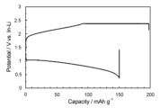
- FIG. 3 shows charge/discharge curves of a solid-state battery using the positive electrode active material prepared in Example 6.
- FIG. 4 shows charge/discharge curves of a solid-state battery using the positive electrode active material prepared in Comparative Example 1.
- the present invention relates to a positive electrode active material.
- the positive electrode active material of the present invention contains porous carbon having pores, elemental sulfur, and lithium halide.
- the elemental sulfur and lithium halide are disposed within the pores of the porous carbon.
- the porous carbon used in the positive electrode active material of the present invention is preferably electrically conductive, so that when elemental sulfur is arranged in the pores of the porous carbon, electronic conductivity is imparted to the sulfur.
- the lithium halide used in the positive electrode active material of the present invention has lithium ion conductivity, and therefore, when elemental sulfur and lithium halide are disposed in the pores of the porous carbon, lithium ion conductivity is imparted to the sulfur.
- the presence of elemental sulfur and lithium halide within the pores of the porous carbon can be confirmed by measuring the positive electrode active material by powder X-ray diffraction (hereinafter also referred to as "XRD") and finding that no diffraction peaks derived from elemental sulfur and lithium halide are observed, or that even if a diffraction peak is observed, it is of extremely low intensity.
- XRD powder X-ray diffraction
- the arrangement of elemental sulfur and lithium halide in the pores of the porous carbon can also be confirmed by mercury porosimetry. Specifically, first, the porous carbon before elemental sulfur and lithium halide are arranged in the pores is measured by mercury porosimetry to measure the most frequent pore size of the pores in the porous carbon. Next, the positive electrode active material is measured by mercury porosimetry to measure the most frequent pore size of the pores. The most frequent pore sizes of both pores are compared, and if the most frequent pore size of the pores in the positive electrode active material is smaller than the most frequent pore size of the pores in the porous carbon, it is determined that elemental sulfur and lithium halide are arranged in the pores of the porous carbon. The most frequent pore size of the pores in the porous carbon can also be measured by analyzing the nitrogen adsorption/desorption isotherm.
- the arrangement of elemental sulfur and lithium halide within the pores of the porous carbon can be confirmed by observing the positive electrode active material with a transmission electron microscope (TEM) equipped with an energy dispersive X-ray spectrometer and mapping the carbon element, sulfur element, and halogen element, as shown in Figures 1 and 2 described below, and observing that the elements are present in an overlapping manner.
- TEM transmission electron microscope
- the presence of elemental sulfur and/or lithium halide outside the pores of the porous carbon is not prevented.
- elemental sulfur and/or lithium halide may be present on a portion of the surface of the porous carbon, or elemental sulfur and/or lithium halide may be present over the entire surface of the porous carbon. Even when elemental sulfur and lithium halide are present outside the pores of the porous carbon in addition to inside the pores, the effects of the present invention are fully achieved.
- the porous carbon has a large number of pores.
- the pores preferably have an open cell structure. That is, the pores open at the surface of the porous carbon, extend toward the inside of the porous carbon, and open at the other end at the surface of the porous carbon.
- the pores may be branched inside the porous carbon.
- the pores may also intersect with other pores inside the porous carbon.
- the most frequent pore size of the pores is preferably within a predetermined range. This increases the surface area of the porous carbon, making it possible to successfully arrange the sulfur element and lithium halide in the pores. From this viewpoint, the most frequent pore size of the pores is preferably 0.1 nm or more, more preferably 1 nm or more, and even more preferably more than 2 nm. From the viewpoint of uniformly impregnating the pores of the porous carbon with sulfur, the most frequent pore size of the pores is preferably 150 nm or less, more preferably 100 nm or less, and even more preferably 50 nm or less. The method for measuring the most frequent pore size will be explained in the examples below.
- the porous carbon has a predetermined amount of mesoscale pores, i.e., mesopores.
- mesopores refers to pores having a pore diameter of more than 2 nm and not more than 50 nm.
- the mesopore volume of the porous carbon is, for example, preferably 0.5 mL/g or more, more preferably 0.8 mL/g or more, and even more preferably 1.0 mL/g or more per unit mass of the porous carbon.
- the mesopore volume of the porous carbon is, for example, preferably 2.0 mL/g or less, more preferably 1.6 mL/g or less, and even more preferably 1.5 mL/g or less, per unit mass of the porous carbon.
- the term "mesopore volume” refers to the volume of pores whose pore diameters are within a specified range as measured by analyzing a nitrogen adsorption/desorption isotherm or as measured by a mercury intrusion porosimeter. The pore diameters of mesopores are shown below.
- the mesopores in the porous carbon have a pore size within a predetermined range. This also allows sufficient amounts of elemental sulfur and lithium halide to be effectively arranged in the pores in order to improve the electronic conductivity and ionic conductivity.
- the pore size of the mesopores is preferably, for example, more than 2 nm, and more preferably 4 nm or more. From the viewpoint of uniformly impregnating the pores of the porous carbon with sulfur, the pore size of the mesopores is, for example, preferably 50 nm or less, more preferably 30 nm or less, and even more preferably 10 nm or less.
- the mesopores in the porous carbon form a three-dimensional network structure, and it is preferable that the mesopores are interconnected, since this allows the sulfur element and lithium halide to be more effectively arranged in the mesopores.
- the porous carbon may have a certain amount of micro-scale pores, i.e., micropores, within a range that does not impair the effects of the present invention.
- Micropores refers to pores with a pore diameter of 2 nm or less.
- the micropore volume per unit mass of the porous carbon is, for example, preferably 0.1 mL/g or more, more preferably 0.3 mL/g or more, and even more preferably 0.4 mL/g or more.
- the micropore volume per unit mass of the porous carbon is, for example, preferably 1.5 mL/g or less, more preferably 1.0 mL/g or less, and even more preferably 0.7 mL/g or less.
- micropore volume refers to the volume of pores having pore diameters within a specified range, as measured by analyzing nitrogen adsorption/desorption isotherms. The pore diameters of the micropores are shown below.
- the micropores in the porous carbon preferably have a lower limit of pore diameter equal to or greater than a predetermined value.
- the pore diameter of the micropores is preferably, for example, 0.1 nm or more, and more preferably 0.5 nm or more.
- the pore diameter of the micropores is preferably, for example, 2 nm or less.
- the total pore volume of the porous carbon is, for example, preferably 0.6 mL/g or more, more preferably 1.0 mL/g or more, and even more preferably 1.3 mL/g or more, per unit mass of the porous carbon.
- the total pore volume of the porous carbon is, for example, preferably 3.0 mL/g or less, more preferably 2.5 mL/g or less, and even more preferably 2.0 mL/g or less, per unit mass of the porous carbon.
- the term "total pore volume” refers to the total volume of all pores contained in the porous carbon.
- the BET specific surface area of the porous carbon is preferably, for example, 100 m 2 /g or more, more preferably 500 m 2 /g or more, even more preferably 700 m 2 /g or more, and even more preferably 1200 m 2 /g or more.
- the BET specific surface area of the porous carbon is, for example, preferably 3000 m 2 /g or less, more preferably 2000 m 2 /g or less, and even more preferably 1800 m 2 /g or less.
- the BET specific surface area is measured, for example, as follows. Porous carbon is heated in a vacuum at 120°C for 1 hour using a pretreatment device "BELPREP-vacII” manufactured by Microtrac-Bell Co., Ltd. Then, using a specific surface area measuring device "BELSORP-miniII” manufactured by Microtrac-Bell Co., Ltd., the specific surface area is calculated by the BET (Brunauer-Emmett-Teller) method from the amount of nitrogen gas adsorbed at liquid nitrogen temperature (77K). The pretreatment is carried out at 120°C for 30 minutes or more in a reduced pressure environment. He is used as the purge gas and N2 is used as the adsorbate.
- BET Brunauer-Emmett-Teller
- porous carbon for example, porous carbon produced by a template method, an alkali activation method, a steam activation method, etc.
- porous carbon produced by the template method from the viewpoint of improving both electronic conductivity and ionic conductivity more than conventional methods.
- the carbon contained in the porous carbon may be, for example, a group of carbonaceous materials called carbon black.
- the type of carbon material is not particularly limited, and the desired effect can be achieved regardless of the type of carbon material used.
- porous carbon Commercially available products can be used as porous carbon.
- “Knobel” registered trademark, manufactured by Toyo Tanso Co., Ltd.
- porous carbon produced by the casting method can be used.
- the sulfur element it is preferable to use elemental sulfur.
- elemental sulfur there are various allotropes of elemental sulfur, such as ⁇ -sulfur S8 , which is orthorhombic sulfur, and ⁇ -sulfur S8 , which is monoclinic sulfur, and in the present invention, any allotrope can be used without limitation.
- the sulfur element it is particularly preferable to use ⁇ -sulfur S8 . This allows the sulfur element to be uniformly impregnated into the pores of the porous carbon. As a result, when the positive electrode active material is used, for example, as a positive electrode material for a solid-state battery, the battery characteristics can be improved.
- the lithium halide it is preferable to use at least one of lithium chloride, lithium bromide, lithium fluoride, and lithium iodide. These can be used alone or in combination of two or more. From the viewpoint of improving lithium ion conductivity compared to conventional methods, it is particularly preferable that the lithium halide contains at least lithium iodide.
- the sulfur element and the lithium halide are arranged in the pores of the porous carbon, so that the electronic conductivity and the ionic conductivity of the sulfur can be improved. Therefore, when the positive electrode active material of the present invention is used as a positive electrode material for a solid-state battery, a high-capacity lithium-sulfur battery can be realized.
- the sulfur element is arranged in the pores of porous carbon having electronic conductivity, thereby imparting the electronic conductivity of the porous carbon to the sulfur.
- the positive electrode active material of the present invention can utilize the electronic conductivity of the porous carbon in addition to the electronic conductivity of the sulfur itself, and therefore the electronic conductivity can be improved compared to the conventional case.
- sulfur has poor ionic conductivity
- the lithium halide is arranged in the pores of the porous carbon together with the sulfur element, thereby imparting the ionic conductivity of the lithium halide to the sulfur.
- the positive electrode active material of the present invention can utilize the ionic conductivity of the lithium halide in addition to the ionic conductivity of the sulfur itself, thereby improving the ionic conductivity more than before.
- the mass ratio of lithium halide to porous carbon is preferably within a predetermined range from the viewpoint of obtaining a positive electrode active material with a capacity per mass that is improved compared to the conventional one.
- the mass ratio of lithium halide to porous carbon is preferably, for example, 0.05 or more, more preferably 0.25 or more, and even more preferably 0.6 or more.
- the mass ratio of lithium halide to porous carbon is preferably, for example, 3.5 or less, and more preferably 2.5 or less.
- the mass ratio of lithium halide to porous carbon refers to the ratio of the total mass of lithium halide disposed within the pores of the porous carbon and lithium halide present outside the pores to the mass of the porous carbon.
- the mass ratio of lithium halide to porous carbon can be adjusted, for example, by adjusting the amount of porous carbon used in the manufacturing method of the positive electrode active material described below, or by adjusting the concentration of the lithium halide solution.
- the mass ratio of lithium halide to porous carbon can be measured by ICP atomic emission spectroscopy. For example, the following measurement method can be used. First, the mass of lithium halide in a sample in which the positive electrode active material has dissolved is measured by ICP atomic emission spectroscopy. At the same time, the mass of the carbon component that remains undissolved is also measured. The mass ratio of lithium halide to porous carbon is calculated based on the mass of lithium halide and the mass of the carbon component.
- the mass ratio of the sulfur element to the porous carbon is, for example, preferably 1.0 or more, more preferably 1.5 or more, and even more preferably 1.8 or more.
- the mass ratio of the sulfur element to the porous carbon has this lower limit, a sufficient amount of the sulfur element is arranged in the pores of the porous carbon, and the proportion of the sulfur element in the positive electrode active material increases. This makes it easier to utilize the high capacity that sulfur inherently has, and as a result, it is easier to obtain a positive electrode active material with a capacity per mass that is improved compared to conventional ones.
- the mass ratio of the sulfur element to the porous carbon is preferably, for example, 2.4 or less, and more preferably 2.2 or less.
- the mass ratio of the sulfur element to the porous carbon has this upper limit, the amount of the lithium halide disposed in the pores of the porous carbon can be prevented from being excessively small. This ensures an opportunity for the ionic conductivity of the lithium halide to be imparted to the sulfur element, and the ionic conductivity can be improved compared to the conventional case.
- the "mass ratio of elemental sulfur to porous carbon” refers to the ratio of the total mass of elemental sulfur disposed within the pores of the porous carbon and elemental sulfur present outside the pores to the mass of the porous carbon.
- the mass ratio of elemental sulfur to porous carbon can be adjusted, for example, by adjusting the amount of porous carbon used in the manufacturing method of the positive electrode active material described below, or by adjusting the amount of sulfur.
- the mass ratio of elemental sulfur to porous carbon can be measured using a thermogravimetry-mass spectrometer (hereinafter also referred to as "TG-MS"). Specifically, the positive electrode active material is heated from room temperature to 200°C in an air atmosphere using a TG-MS (TG-DTA Thermoplus TG8120, Rigaku Corporation, MS GCMS-QP2010Plus, Shimadzu Corporation). Next, the amount of gas generated at high temperatures, such as 400°C, above the volatilization temperature of sulfur, is measured, and the mass ratio can be calculated based on the amount of sulfur-containing gas generated by volatilization.
- TG-MS thermogravimetry-mass spectrometer
- the mass ratio of lithium halide to elemental sulfur is, for example, preferably 0.01 or more, more preferably 0.2 or more, and even more preferably 0.3 or more.
- the mass ratio of lithium halide to elemental sulfur has this lower limit, the opportunity for the ionic conductivity of lithium halide to be imparted to elemental sulfur increases, thereby improving the lithium ion conductivity more than before.
- the mass ratio of lithium halide to sulfur element is preferably 2.0 or less, more preferably 1.2 or less.
- the mass ratio of lithium halide to sulfur element has this upper limit, the amount of sulfur element arranged in the pores of the porous carbon becomes relatively larger than the amount of lithium halide.
- the "mass ratio of lithium halide to elemental sulfur” refers to the ratio of the total mass of lithium halide disposed within the pores of the porous carbon and lithium halide present outside the pores to the total mass of elemental sulfur disposed within the pores of the porous carbon and elemental sulfur disposed outside the pores of the porous carbon.
- the mass ratio of lithium halide to elemental sulfur can be adjusted, for example, by adjusting the amount of sulfur used in the manufacturing method of the positive electrode active material described below, or by adjusting the concentration of the lithium halide solution.
- the mass ratio of lithium halide to elemental sulfur can be measured by ICP atomic emission spectrometry.
- the mass ratio of the porous carbon to the total mass of the sulfur element and the lithium halide is preferably, for example, 0.05 or more.
- the mass ratio is equal to or more than this lower limit, the opportunity for the electronic conductivity of the porous carbon and the ionic conductivity of the lithium halide to be imparted to the sulfur element increases, thereby improving both the electronic conductivity and the lithium ion conductivity more than before.
- the mass ratio of the porous carbon to the total mass of the sulfur element and the lithium halide is, for example, preferably 0.15 or more, and even more preferably 0.23 or more.
- the mass ratio of the porous carbon to the total mass of the sulfur element and the lithium halide is preferably, for example, 0.60 or less.
- the mass ratio is preferably, for example, 0.60 or less.
- the mass ratio of the porous carbon to the total mass of the sulfur element and the lithium halide is, for example, more preferably 0.45 or less, and even more preferably 0.42 or less.
- the mass ratio of porous carbon to the total mass of elemental sulfur and lithium halide refers to the ratio of the total mass of elemental sulfur and lithium halide disposed within the pores of the porous carbon and elemental sulfur and lithium halide disposed outside the pores of the porous carbon to the total mass of elemental sulfur and lithium halide disposed within the pores of the porous carbon and elemental sulfur and lithium halide present outside the pores.
- the mass ratio of the porous carbon to the total mass of elemental sulfur and lithium halide can be adjusted, for example, by adjusting the amount of sulfur used in the manufacturing method of the positive electrode active material described below, or by adjusting the concentration of the lithium halide solution.
- the mass ratio of porous carbon to the total mass of elemental sulfur and lithium halide can be measured by ICP atomic emission spectrometry.
- the following measurement method can be used. First, the masses of elemental sulfur and lithium halide in a sample in which the positive electrode active material has dissolved are measured by ICP atomic emission spectrometry. At the same time, the mass of the carbon component that remains undissolved is also measured. Based on the masses of elemental sulfur and lithium halide and the mass of the carbon component, the mass ratio of porous carbon to the total mass of elemental sulfur and lithium halide is calculated.
- the positive electrode active material of the present invention preferably has a particle diameter D 50 in a predetermined range.
- the particle diameter D 50 of the positive electrode active material is preferably, for example, 0.1 ⁇ m or more, more preferably 0.5 ⁇ m or more, and even more preferably 1 ⁇ m or more.
- the particle diameter D 50 of the positive electrode active material is preferably, for example, 20 ⁇ m or less, more preferably 10 ⁇ m or less, and even more preferably 5 ⁇ m or less.
- the particle size D50 of the positive electrode active material refers to the volume cumulative particle size D50 at a cumulative volume of 50 % by volume measured by a laser diffraction scattering type particle size distribution measurement method.
- particle size D50 when used, it means the volume cumulative particle size D50 .
- the particle size D50 of the sulfur element and lithium halide arranged in the pores of the porous carbon in the positive electrode active material of the present invention is sufficiently smaller than the particle size D50 of the porous carbon, the particle size D50 of the positive electrode active material can be considered to be almost the same as the particle size D50 of the porous carbon.
- the positive electrode active material may have other components disposed within the pores of the porous carbon, and in addition to or instead of this, other components may be present outside the pores of the porous carbon.
- other components include lithium salt compounds such as lithium carbonate and lithium sulfate.
- the positive electrode active material may contain unavoidable impurities to the extent that they do not adversely affect the effects of the present invention, for example, less than 3% by mass, and preferably less than 1% by mass, of the entire positive electrode active material.
- porous carbon having pores which is one of the raw materials for the positive electrode active material, is prepared. If necessary, the porous carbon can be subjected to a pretreatment such as drying.
- a solution of lithium halide which is one of the raw materials of the positive electrode active material, is prepared together with the porous carbon.
- the lithium halide source in the lithium halide solution at least one of lithium chloride, lithium bromide, lithium fluoride, and lithium iodide can be used alone or in combination of two or more.
- these lithium halide sources it is particularly preferable to use lithium iodide alone in order to improve electronic conductivity and ionic conductivity.
- the solvent for the lithium halide solution include various organic solvents such as alcohols, carboxylic acids, and ketones.
- the alcohols include methanol, ethanol, propanol, and butanol.
- the carboxylic acids include acetic acid.
- the ketones include acetone.
- it is particularly preferable to use ethanol because it has a good balance between ease of handling and high solubility.
- the concentration of the lithium halide solution is, for example, preferably 0.05 mol/L or more, more preferably 0.15 mol/L or more, and even more preferably 0.35 mol/L or more. From the viewpoint of being able to arrange the lithium halide well evenly in the pores of the porous carbon, the concentration of the lithium halide solution is, for example, preferably 1.50 mol/L or less, and more preferably 1.20 mol/L or less. The concentration of the lithium halide solution can be set to an appropriate value according to the amount of lithium halide to be placed in the pores of the porous carbon.
- the lithium halide solution is mixed with the porous carbon to obtain a dispersion liquid.
- the mixing of the porous carbon and the lithium halide solution can be carried out, for example, by stirring using a magnetic stirrer, mixing in a mortar, mixing in a ball mill, or the like.
- the ratio of the porous carbon in the dispersion is, for example, preferably 3% by mass or more, more preferably 5% by mass or more, relative to the lithium halide solution, and from the viewpoint of being able to effectively improve the battery characteristics, the ratio of the porous carbon in the dispersion is, for example, preferably 15% by mass or less, more preferably 10% by mass or less, relative to the lithium halide solution.
- the dispersion Once the dispersion has been prepared, it is heated and the lithium halide in the dispersion is impregnated into the pores of the porous carbon.
- the dispersion is preferably heated, for example, in an argon gas atmosphere.
- the heating is preferably performed under pressure in a closed container.
- the pressure in the system is preferably set to, for example, 0.05 MPa or more, expressed as a gauge pressure, from the viewpoint of ensuring the impregnation of lithium halide.
- the pressure in the system is preferably set to, for example, 15 MPa or less, more preferably 10 MPa or less, and even more preferably 5 MPa or less, expressed as a gauge pressure.
- the temperature in the system is preferably set to, for example, 50° C. or higher, and more preferably set to 100° C. or higher.
- the temperature is preferably set to, for example, 600° C. or lower, and more preferably set to 200° C. or lower.
- the heating time is, for example, preferably 10 minutes or more, more preferably 20 minutes or more, and, for example, preferably 8 hours or less, more preferably 2 hours or less.
- the dispersion After heating the dispersion, the dispersion is subjected to a pressure reduction process until the pressure reaches normal pressure.
- the pressure reduction process causes the dispersion medium in the dispersion to evaporate and be removed from the dispersion.
- the dispersion liquid is subjected to a drying treatment.
- the drying treatment removes the dispersion medium that was not completely removed from the dispersion liquid by the reduced pressure treatment.
- There are no particular limitations on the temperature and time of the drying treatment so long as it is sufficient to remove the dispersion medium from the porous carbon. For example, it is preferable to dry at a temperature of 300°C or higher and 500°C or lower for 1 hour or higher and 3 hours or lower.
- lithium halide is present at least within the pores of the porous carbon.
- sulfur which is one of the raw materials for the positive electrode active material.
- elemental sulfur such as ⁇ -sulfur S 8 and ⁇ -sulfur S 8 can be used alone or in combination of two or more kinds.
- the intermediate obtained in the above process is mixed with sulfur to obtain a mixed powder.
- the two can be mixed using a stirrer such as a mortar or a ball mill.
- the proportion of sulfur in the mixed powder is preferably, for example, 1 mass% or more, more preferably 1.5 mass% or more, and even more preferably 2 mass% or more, relative to the porous carbon contained in the intermediate.
- the proportion of sulfur in the mixed powder is preferably 3 mass% or less, relative to the porous carbon contained in the intermediate.
- the proportion of sulfur in the mixed powder is preferably, for example, 2% by mass or more relative to the lithium halide contained in the intermediate. Also, from the viewpoint of being able to effectively improve the battery characteristics, the proportion of sulfur in the mixed powder is preferably, for example, 6% by mass or less relative to the lithium halide contained in the intermediate, and more preferably 3% by mass or less.
- the intermediate and sulfur are preferably mixed while the sulfur is in a molten state.
- the pores of the porous carbon can be reliably filled with sulfur.
- the temperature when mixing the two is preferably set to, for example, 120° C. or higher, and more preferably set to 150° C. or higher.
- the temperature is preferably set to, for example, 180° C. or lower, and more preferably set to 160° C. or lower.
- the mixing time is, for example, preferably 3 hours or more, more preferably 5 hours or more, and, for example, preferably 16 hours or less, more preferably 14 hours or less, and further preferably 7 hours or less.
- the pressure in the system is preferably set to, for example, 0.01 MPa or more, and more preferably set to 0.1 MPa or more. Furthermore, the pressure in the system, expressed as a gauge pressure, is preferably set to, for example, 15 MPa or less, more preferably set to 10 MPa or less, even more preferably set to 5 MPa or less, and even more preferably set to 1 MPa or less.
- the steps of impregnating the porous carbon with lithium halide and then impregnating it with sulfur are carried out in that order, but instead, the steps may be carried out in the reverse order, that is, after impregnating the porous carbon with elemental sulfur, the lithium halide may be impregnated.
- the positive electrode active material of the present invention can be made into a positive electrode mixture by mixing it with a conductive material, a binder, etc.
- a solid electrolyte can be contained in the positive electrode mixture.
- the solid electrolyte preferably has ion conductivity such as lithium ion conductivity.
- ion conductivity such as lithium ion conductivity.
- inorganic solid electrolytes such as sulfide solid electrolytes, oxide solid electrolytes, nitride solid electrolytes, and halide solid electrolytes, and organic polymer electrolytes such as polymer electrolytes can be mentioned.
- the solid electrolyte is preferably a sulfide solid electrolyte.
- the sulfide solid electrolyte can be the same as the sulfide solid electrolyte used in a general solid battery.
- the sulfide solid electrolyte may be, for example, one containing Li and S and having lithium ion conductivity.
- the sulfide solid electrolyte may be any of a crystalline material, a glass ceramic, and a glass.
- the sulfide solid electrolyte may have an argyrodite-type crystal structure.
- Examples of such sulfide solid electrolytes include Li 2 S-P 2 S 5 , Li 2 S-P 2 S 5 -LiX (wherein "X" represents one or more halogen elements), Li 2 S-P 2 S 5 -P 2 O 5 , Li 2 S-Li 3 PO 4 -P 2 S 5 , Li 3 PS 4 , Li 4 P 2 S 6 , Li 10 GeP 2 S 12 , Li 3.25 Ge 0.25 P 0.75 S 4 , Li 7 P 3 S 11 , Li 3.25 P 0.95 S 4 , Li a PS b X c (wherein "X" represents one or more halogen elements; a represents a number of 3.0 or more and 9.0 or less; b represents a number of 3.5 or more and 6.0 or less; and c represents a number of 0.1 or more and 3.0 or less).
- the sulfide solid electrolytes described in WO 2013/099834 and WO 2015/001818 can be mentioned.
- a positive electrode layer can be formed from the electrode mixture thus obtained.
- a solid-state battery can then be produced from the positive electrode layer, a solid electrolyte layer containing a solid electrolyte, and a negative electrode layer.
- the negative electrode active material that constitutes the negative electrode layer include carbon, silicon, and lithium.
- a solid-state battery can be produced, for example, by stacking a positive electrode layer, a solid electrolyte layer, and a negative electrode layer and pressurizing them.
- solid-state battery includes solid-state batteries that do not contain any liquid or gel-like substance as an electrolyte, as well as those that contain, for example, 50% by mass or less, 30% by mass or less, or 10% by mass or less of a liquid or gel-like substance as an electrolyte.
- the battery having the positive electrode active material of the present invention is preferably a lithium ion battery, and more preferably a lithium sulfur battery.
- the battery having the positive electrode active material of the present invention may be either a primary battery or a secondary battery, but is preferably used as a secondary battery, and is particularly preferably used as a lithium secondary battery.
- the term "lithium secondary battery” is intended to broadly encompass secondary batteries in which lithium ions move between the positive and negative electrodes to charge and discharge.
- the following positive electrode active material and a method for producing the same are further disclosed.
- a porous carbon having pores, a sulfur element, and a lithium halide The positive electrode active material, wherein the sulfur element and the lithium halide are disposed in the pores of the porous carbon.
- a mass ratio of the lithium halide to the porous carbon is 0.1 or more and 3.0 or less.
- Example 1 Preparation of Dispersion Porous carbon (Knobel (registered trademark), manufactured by Toyo Tanso Co., Ltd.) having the most frequent pore size shown in Table 1 and lithium iodide were prepared. The physical properties of the porous carbon are as shown in the same table. A dispersion was prepared by mixing the porous carbon with a 1.00 mol/L ethanol solution of lithium iodide so that the mass ratio of lithium iodide to the porous carbon was as shown in Table 1. (2) Heat treatment of dispersion The dispersion was placed in a sealed container, and heated to 120°C while circulating argon in the sealed container, and the gauge pressure was set to 0.1 MPa, and this state was maintained for 30 minutes.
- Examples 2 to 7 A positive electrode active material was obtained in the same manner as in Example 1, except that the concentration of the lithium iodide solution was changed so that the mass ratio of lithium iodide to the porous carbon was as shown in Table 1.
- Comparative Example 1 A positive electrode active material was obtained in the same manner as in Example 1, except that lithium iodide was not used.
- Example 2 The porous carbon used in Example 1 was replaced with one having the most frequent pore size shown in Table 1. In addition, lithium iodide was not used. A positive electrode active material was obtained in the same manner as in Example 1 except for the above.
- the most frequent pore size of the porous carbon used in the examples and comparative examples was measured by the following method.
- the particle size D50 of the positive electrode active materials obtained in the examples and comparative examples was measured by the above-mentioned method.
- the particle size D50 of the positive electrode active materials obtained in the examples and comparative examples was in the range of 1 ⁇ m or more and 5 ⁇ m or less.
- the positive electrode active materials obtained in the examples and comparative examples it was confirmed by the above-mentioned TEM observation that elemental sulfur and lithium iodide were arranged in the pores of the porous carbon.
- TEM-EDS images of the positive electrode active materials for Example 6 and Comparative Example 1 are shown in Figures 1 and 2.
- XRD measurement was performed on the positive electrode active materials obtained in the examples and comparative examples, and I 1 S , which is the intensity of the peak derived from sulfur element, and I 1 X , which is the intensity of the peak derived from lithium iodide, were measured.
- the ratio of I 1 X to I 1 S was calculated.
- Measuring I 1 X means that lithium iodide is present outside the pores of the porous carbon.
- a positive value of I 1 X /I 1 S means that sulfur element and lithium iodide are present outside the pores of the porous carbon.
- the conditions of the XRD measurement were as follows.
- the ionic conductivity of the positive electrode active materials obtained in the examples and comparative examples was measured by the following method.
- solid-state batteries were produced using the positive electrode active materials obtained in the Examples and Comparative Examples by the following method, and the battery characteristics were measured by the following method. The results are shown in Table 1 below.
- the nitrogen adsorption and desorption isotherms were analyzed to measure the nitrogen adsorption and desorption.
- a gas adsorption measuring device (Micromeritics 3Flex) was used for the nitrogen adsorption and desorption measurement.
- the porous carbon was heated at 400°C for 3 hours under reduced pressure of 10 Pa.
- the obtained adsorption isotherms were analyzed using the BJH method, and the most frequent pore size of the porous carbon in the range of 0.1 nm to 150 nm was calculated.
- the analysis software used was 3Flex version 5.02, which was attached to the gas adsorption measuring device.
- the present inventors have confirmed that the most frequent pore size of the positive electrode active material is smaller than the most frequent pore size of the porous carbon before lithium iodide and elemental sulfur are disposed in the pores of the porous carbon.
- the positive electrode active materials were those obtained in the Examples and Comparative Examples, the solid electrolyte powder used in the positive electrode layer and the solid electrolyte layer was Li 5.4 PS 4.4 Cl 0.8 Br 0.8 having an argyrodite-type crystal structure, and the negative electrode active material in the negative electrode layer was an In—Li alloy.
- the powder of the positive electrode active material obtained in each of the Examples and Comparative Examples and a solid electrolyte powder were mixed in a mortar in a mass ratio of 60:40 to prepare a positive electrode mixture for the positive electrode layer.
- a solid-state battery cell was produced by the following method.
- the lower opening of a polypropylene cylinder (opening diameter 10.5 mm, height 18 mm) with openings at the top and bottom was blocked with a negative electrode (made of SUS), a solid electrolyte powder was placed on it, and the solid electrolyte layer was then formed by uniaxial pressing at 200 MPa.
- the positive electrode was once removed, 10 mg of a positive electrode mixture was placed on the solid electrolyte layer and blocked again with the positive electrode, and then uniaxial pressing was performed at 560 MPa to laminate the positive electrode layer and the solid electrolyte layer.
- the cylinder was turned upside down, the negative electrode was once removed, an In-Li alloy foil was placed on the solid electrolyte layer and blocked again with the negative electrode, and finally, the positive and negative electrodes were sandwiched between them with a load of 6 using a clasp vise to produce a solid battery cell in which the positive electrode layer, the solid electrolyte layer, and the negative electrode layer were laminated.
- the solid-state battery cell was produced in a glove box substituted with argon gas at a dew point temperature of -60 ° C. In an environmental tester maintained at 25°C, the prepared solid battery cell was connected to a charge/discharge measuring device to evaluate the battery characteristics.
- the discharge capacity per sulfur mass was set to 1000mAh/g, and the discharge capacity per positive electrode mixture mass was set to 400mAh/g.
- the current during charge/discharge was set to 4.0mA as the 1C rate.
- the positive electrode active materials of Examples 1 to 7 in which sulfur and lithium iodide were impregnated into the porous carbon had improved ionic conductivity compared to the positive electrode active materials of Comparative Examples 1 to 4 in which lithium iodide was not impregnated.
- the positive electrode active materials of Comparative Examples 1 to 4 had ionic conductivity below the detection limit.
- the solid-state batteries obtained in Examples 1 to 7 have higher discharge capacity per mass of sulfur and higher discharge capacity per positive electrode layer than the solid-state batteries obtained in Comparative Examples 1 to 4.
- the solid-state batteries obtained in Comparative Examples 2 and 3 had relatively high discharge capacity per mass of sulfur and discharge capacity per positive electrode layer, but the ionic conductivity of the positive electrode active material was below the detection limit. This is thought to be because the positive electrode active materials of each Comparative Example were produced without using lithium iodide, and therefore the improvement in ionic conductivity due to lithium iodide was not obtained. Therefore, it is expected that the discharge capacity of the solid-state batteries obtained in each Comparative Example will be drastically reduced, especially at high C rates. In contrast, the solid-state batteries obtained in each Example had high discharge capacity per mass of sulfur and discharge capacity per positive electrode layer, and the ionic conductivity of the positive electrode active material was also improved. Therefore, it is expected that the solid-state batteries obtained in each Example will have high discharge capacity even at high C rates.
Landscapes
- Chemical & Material Sciences (AREA)
- Chemical Kinetics & Catalysis (AREA)
- Electrochemistry (AREA)
- General Chemical & Material Sciences (AREA)
- Battery Electrode And Active Subsutance (AREA)
Priority Applications (1)
| Application Number | Priority Date | Filing Date | Title |
|---|---|---|---|
| JP2024576867A JPWO2024166918A1 (https=) | 2023-02-07 | 2024-02-06 |
Applications Claiming Priority (2)
| Application Number | Priority Date | Filing Date | Title |
|---|---|---|---|
| JP2023017168 | 2023-02-07 | ||
| JP2023-017168 | 2023-02-07 |
Publications (1)
| Publication Number | Publication Date |
|---|---|
| WO2024166918A1 true WO2024166918A1 (ja) | 2024-08-15 |
Family
ID=92262653
Family Applications (1)
| Application Number | Title | Priority Date | Filing Date |
|---|---|---|---|
| PCT/JP2024/003975 Ceased WO2024166918A1 (ja) | 2023-02-07 | 2024-02-06 | 正極活物質及びその製造方法 |
Country Status (2)
| Country | Link |
|---|---|
| JP (1) | JPWO2024166918A1 (https=) |
| WO (1) | WO2024166918A1 (https=) |
Cited By (1)
| Publication number | Priority date | Publication date | Assignee | Title |
|---|---|---|---|---|
| EP4503183A4 (en) * | 2022-03-31 | 2026-01-21 | Nissan Motor | POSITIVE ELECTRODE MATERIAL AND SECONDARY BATTERY USING IT |
Citations (4)
| Publication number | Priority date | Publication date | Assignee | Title |
|---|---|---|---|---|
| JPH04500288A (ja) * | 1988-08-29 | 1992-01-16 | アルタス・コーポレーション | リチウム―塩化銅の充電可能なセル内での電圧調整を改善するための添加剤 |
| US20220013778A1 (en) * | 2020-07-13 | 2022-01-13 | International Business Machines Corporation | Rechargeable metal halide battery with intercalation anode |
| JP2022076603A (ja) * | 2020-11-10 | 2022-05-20 | 学校法人 関西大学 | リチウム-硫黄系二次電池用電解液およびリチウム-硫黄系二次電池 |
| WO2024009978A1 (ja) * | 2022-07-04 | 2024-01-11 | 出光興産株式会社 | 複合粉末、正極合材及びアルカリ金属イオン電池 |
-
2024
- 2024-02-06 JP JP2024576867A patent/JPWO2024166918A1/ja active Pending
- 2024-02-06 WO PCT/JP2024/003975 patent/WO2024166918A1/ja not_active Ceased
Patent Citations (4)
| Publication number | Priority date | Publication date | Assignee | Title |
|---|---|---|---|---|
| JPH04500288A (ja) * | 1988-08-29 | 1992-01-16 | アルタス・コーポレーション | リチウム―塩化銅の充電可能なセル内での電圧調整を改善するための添加剤 |
| US20220013778A1 (en) * | 2020-07-13 | 2022-01-13 | International Business Machines Corporation | Rechargeable metal halide battery with intercalation anode |
| JP2022076603A (ja) * | 2020-11-10 | 2022-05-20 | 学校法人 関西大学 | リチウム-硫黄系二次電池用電解液およびリチウム-硫黄系二次電池 |
| WO2024009978A1 (ja) * | 2022-07-04 | 2024-01-11 | 出光興産株式会社 | 複合粉末、正極合材及びアルカリ金属イオン電池 |
Cited By (1)
| Publication number | Priority date | Publication date | Assignee | Title |
|---|---|---|---|---|
| EP4503183A4 (en) * | 2022-03-31 | 2026-01-21 | Nissan Motor | POSITIVE ELECTRODE MATERIAL AND SECONDARY BATTERY USING IT |
Also Published As
| Publication number | Publication date |
|---|---|
| JPWO2024166918A1 (https=) | 2024-08-15 |
Similar Documents
| Publication | Publication Date | Title |
|---|---|---|
| Xu et al. | Graphite-based lithium ion battery with ultrafast charging and discharging and excellent low temperature performance | |
| Huang et al. | Direct synthesis of 3D hierarchically porous carbon/Sn composites via in situ generated NaCl crystals as templates for potassium-ion batteries anode | |
| Li et al. | Controllable synthesis of uniform mesoporous H-Nb 2 O 5/rGO nanocomposites for advanced lithium ion hybrid supercapacitors | |
| Chen et al. | Co 9 S 8 embedded into N/S doped carbon composites: in situ derivation from a sulfonate-based metal–organic framework and its electrochemical properties | |
| He et al. | Direct impregnation of SeS 2 into a MOF-derived 3D nanoporous Co–N–C architecture towards superior rechargeable lithium batteries | |
| Ye et al. | Tuning the porous structure of carbon hosts for loading sulfur toward long lifespan cathode materials for Li–S batteries | |
| Gao et al. | Porous Li 4 Ti 5 O 12–TiO 2 nanosheet arrays for high-performance lithium-ion batteries | |
| Xiao et al. | Porous carbon nanotubes etched by water steam for high-rate large-capacity lithium–sulfur batteries | |
| Hou et al. | MIL-100 (V) and MIL-100 (V)/rGO with various valence states of vanadium ions as sulfur cathode hosts for lithium-sulfur batteries | |
| Xu et al. | High-energy lithium-ion hybrid supercapacitors composed of hierarchical urchin-like WO 3/C anodes and MOF-derived polyhedral hollow carbon cathodes | |
| Jiang et al. | Selenium in nitrogen-doped microporous carbon spheres for high-performance lithium–selenium batteries | |
| Zhang et al. | Selenium/interconnected porous hollow carbon bubbles composites as the cathodes of Li–Se batteries with high performance | |
| Marino et al. | Nanoconfined phosphorus in mesoporous carbon as an electrode for Li-ion batteries: performance and mechanism | |
| Nagao et al. | All-solid-state lithium–sulfur batteries with three-dimensional mesoporous electrode structures | |
| JP6756742B2 (ja) | リチウム−硫黄電池用の微多孔性カーボンナノシートを含む硫黄−炭素複合体およびそれを調製するためのプロセス | |
| Prosini et al. | Sodium extraction from sodium iron phosphate with a Maricite structure | |
| KR102522173B1 (ko) | 나트륨이차전지용 질소-도핑된 탄소가 코팅된 음극 활물질 및 그 제조방법 | |
| JP2010095390A (ja) | メソポーラス炭素複合材料およびこれを用いた二次電池 | |
| KR101992668B1 (ko) | 비수 전해질 이차전지용 혼합 음극 재료의 제조 방법 및 이의 제조 방법에 의해 얻어지는 비수 전해질 이차전지용 혼합 음극 재료 | |
| WO2016075916A1 (ja) | 硫黄-カーボン複合体、硫黄―カーボン複合体を含む電極を備えた非水電解質電池、及び硫黄-カーボン複合体の製造方法 | |
| Fang et al. | Design and synthesis of two-dimensional porous Fe-doped LiCoPO4 nano-plates as improved cathode for lithium ion batteries | |
| Shi et al. | Facile synthesis of scalable pore-containing silicon/nitrogen-rich carbon composites from waste contact mass of organosilane industry as anode materials for lithium-ion batteries | |
| Qian et al. | Zn-MOF derived micro/meso porous carbon nanorod for high performance lithium–sulfur battery | |
| Lapornik et al. | Manganese modified zeolite silicalite-1 as polysulphide sorbent in lithium sulphur batteries | |
| KR20220143991A (ko) | 고정화 셀레늄, 그 제조방법, 및 재충전식 전지에서 고정화 셀레늄의 사용 |
Legal Events
| Date | Code | Title | Description |
|---|---|---|---|
| 121 | Ep: the epo has been informed by wipo that ep was designated in this application |
Ref document number: 24753361 Country of ref document: EP Kind code of ref document: A1 |
|
| WWE | Wipo information: entry into national phase |
Ref document number: 2024576867 Country of ref document: JP |
|
| NENP | Non-entry into the national phase |
Ref country code: DE |
|
| 122 | Ep: pct application non-entry in european phase |
Ref document number: 24753361 Country of ref document: EP Kind code of ref document: A1 |