WO2024166316A1 - 基地局装置、端末装置、及び無線通信システム - Google Patents
基地局装置、端末装置、及び無線通信システム Download PDFInfo
- Publication number
- WO2024166316A1 WO2024166316A1 PCT/JP2023/004415 JP2023004415W WO2024166316A1 WO 2024166316 A1 WO2024166316 A1 WO 2024166316A1 JP 2023004415 W JP2023004415 W JP 2023004415W WO 2024166316 A1 WO2024166316 A1 WO 2024166316A1
- Authority
- WO
- WIPO (PCT)
- Prior art keywords
- slot
- sbfd
- symbol
- uplink
- base station
- Prior art date
- Legal status (The legal status is an assumption and is not a legal conclusion. Google has not performed a legal analysis and makes no representation as to the accuracy of the status listed.)
- Ceased
Links
Images




Classifications
-
- H—ELECTRICITY
- H04—ELECTRIC COMMUNICATION TECHNIQUE
- H04L—TRANSMISSION OF DIGITAL INFORMATION, e.g. TELEGRAPHIC COMMUNICATION
- H04L27/00—Modulated-carrier systems
- H04L27/26—Systems using multi-frequency codes
- H04L27/2601—Multicarrier modulation systems
- H04L27/2647—Arrangements specific to the receiver only
- H04L27/2655—Synchronisation arrangements
- H04L27/2666—Acquisition of further OFDM parameters, e.g. bandwidth, subcarrier spacing, or guard interval length
-
- H—ELECTRICITY
- H04—ELECTRIC COMMUNICATION TECHNIQUE
- H04L—TRANSMISSION OF DIGITAL INFORMATION, e.g. TELEGRAPHIC COMMUNICATION
- H04L5/00—Arrangements affording multiple use of the transmission path
- H04L5/003—Arrangements for allocating sub-channels of the transmission path
- H04L5/0044—Allocation of payload; Allocation of data channels, e.g. PDSCH or PUSCH
-
- H—ELECTRICITY
- H04—ELECTRIC COMMUNICATION TECHNIQUE
- H04W—WIRELESS COMMUNICATION NETWORKS
- H04W28/00—Network traffic management; Network resource management
- H04W28/02—Traffic management, e.g. flow control or congestion control
- H04W28/06—Optimizing the usage of the radio link, e.g. header compression, information sizing, discarding information
-
- H—ELECTRICITY
- H04—ELECTRIC COMMUNICATION TECHNIQUE
- H04W—WIRELESS COMMUNICATION NETWORKS
- H04W72/00—Local resource management
- H04W72/04—Wireless resource allocation
- H04W72/044—Wireless resource allocation based on the type of the allocated resource
- H04W72/0446—Resources in time domain, e.g. slots or frames
-
- H—ELECTRICITY
- H04—ELECTRIC COMMUNICATION TECHNIQUE
- H04W—WIRELESS COMMUNICATION NETWORKS
- H04W72/00—Local resource management
- H04W72/04—Wireless resource allocation
- H04W72/044—Wireless resource allocation based on the type of the allocated resource
- H04W72/0453—Resources in frequency domain, e.g. a carrier in FDMA
-
- H—ELECTRICITY
- H04—ELECTRIC COMMUNICATION TECHNIQUE
- H04W—WIRELESS COMMUNICATION NETWORKS
- H04W72/00—Local resource management
- H04W72/20—Control channels or signalling for resource management
- H04W72/23—Control channels or signalling for resource management in the downlink direction of a wireless link, i.e. towards a terminal
- H04W72/231—Control channels or signalling for resource management in the downlink direction of a wireless link, i.e. towards a terminal the control data signalling from the layers above the physical layer, e.g. RRC or MAC-CE signalling
Definitions
- the present invention relates to a base station device, a terminal device, and a wireless communication system.
- Wireless communication systems require efficient use of radio resources.
- 3GPP registered trademark
- SBFD Sub-band Full Duplex
- SBFD is a method that allows frequency resources in the same time resource of TDD (Time Division Duplex) to be allocated to both the uplink and downlink.
- the frequency resource may be a resource block.
- a target slot is used as an uplink resource by one terminal device, but is used as a downlink resource by another terminal device.
- the base station device performs reception on the uplink resource and transmission on the downlink resource at the same time in the target slot.
- 3GPP TS 36.133 V17.7.0 3GPP TS 36.211 V17.2.0 3GPP TS 36.212 V17.1.0 3GPP TS 36.213 V17.3.0 3GPP TS 36.214 V17.0.0 3GPP TS 36.300 V17.2.0 3GPP TS 36.321 V17.2.0 3GPP TS 36.322 V17.0.0 3GPP TS 36.323 V17.1.0 3GPP TS 36.331 V17.2.0 3GPP TS 37.324 V17.0.0 3GPP TS 37.340 V17.2.0 3GPP TS 38.133 V17.7.0 3GPP TS 38.201 V17.0.0 3GPP TS 38.202 V17.2.0 3GPP TS 38.211 V17.3.0 3GPP TS 38.212 V17.3.0 3GPP TS 38.213 V17.3.0 3GPP TS 38.214 V17.3.0 3GPP TS 38.215 V17.2.0 3GPP TS 38.
- SBFD the method of notifying and determining the slots that make up the SBFD is still under consideration and has not yet been determined. Therefore, for example, in SBFD, when switching from a downlink slot to an uplink slot in the first slot on the first frequency, the slot configuration and the symbol configuration within the switched slot have not yet been determined.
- one disclosure provides a base station device, a terminal device, and a wireless communication system that can set the SBFD configuration.
- a base station device in a wireless communication system that supports a first communication in which uplink communication and downlink communication are performed at the same timing using different frequencies in a first slot in a carrier, the base station device having a notification unit that notifies a terminal device of first information regarding the first communication, and a communication unit that performs the uplink communication with the terminal device in the first slot in response to the first information, the first information including information regarding uplink resources for the uplink communication.
- One disclosure is that it is possible to set the configuration of the SBFD.
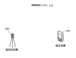
- FIG. 1 is a diagram showing an example of the configuration of a wireless communication system 10.
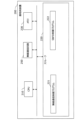
- FIG. 2 is a diagram showing an example of the configuration of the base station device 200.
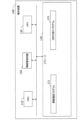
- FIG. 3 is a diagram illustrating an example of the configuration of the terminal device 100.
- FIG. 4 is a diagram showing an example of variables in the first method.
- FIG. 5 is a diagram showing an example of variables in the second method.
- FIG. 6 is a diagram showing an example of variables in the third method.
- FIG. 7 is a diagram showing an example of variables in the fourth method.
- FIG. 8 is a diagram showing an example of variables in the fifth method.
- FIG. 9 is a diagram showing an example of variables in the sixth method.
- FIG. 10 is a diagram showing an example of variables in the seventh method.
- FIG. 10 is a diagram showing an example of variables in the seventh method.
- FIG. 11 is a diagram showing an example of a specification in the second method.
- FIG. 12 is a diagram showing an example of a specification in the third method.
- FIG. 13 is a diagram showing an example of a specification in the fourth method.
- FIG. 14 is a diagram showing an example of a specification in the fifth method.
- FIG. 15 is a diagram showing an example of a specification in the sixth method.
- Fig. 1 is a diagram showing an example of the configuration of a wireless communication system 10.
- the wireless communication system 10 includes a base station device 200 and a terminal device 100.
- the wireless communication system 10 is a wireless communication system that supports SBFD.
- the base station device 200 is a device that wirelessly connects to the terminal device 100 and performs wireless communication, and is, for example, an eNodeB or gNodeB.
- the base station device 200 supports SBFD and supports communication generations such as 5G and NR (New Radio).
- the base station device 200 may be configured as a single device, or may be configured as multiple devices such as a CU (Central Unit) and DU (Distributed Unit).
- the terminal device 100 is a communication device that wirelessly connects to the base station device 200 and transmits and receives data, and is, for example, a smartphone or tablet terminal.
- the terminal device 100 supports SBFD.
- the base station device 200 notifies the terminal device 100 of the wireless resources corresponding to SBFD.
- the terminal device 100 uses the wireless resources according to the instructions of the base station device 200.
- ⁇ Configuration example of base station device 200> 2 is a diagram showing an example of the configuration of the base station device 200.
- the base station device 200 includes a CPU (Central Processing Unit) 210, a storage 220, a memory 230, and a wireless communication circuit 250.
- CPU Central Processing Unit
- Storage 220 is an auxiliary storage device such as a flash memory, HDD (Hard Disk Drive), or SSD (Solid State Drive) that stores programs and data.
- Storage 220 stores a wireless communication control program 221 and an SBFD control program 222.
- Memory 230 is an area into which programs stored in storage 220 are loaded. Memory 230 may also be used as an area in which programs store data.
- the wireless communication circuit 250 is a device that performs wireless communication with the terminal device 100.
- the base station device 200 transmits and receives signals (messages) to and from the terminal device 100 via the wireless communication circuit 250.
- the CPU 210 is a processor that loads the programs stored in the storage 220 into the memory 230, executes the loaded programs, configures each component, and realizes each process.
- the CPU 210 executes a wireless communication control program to construct a communication unit and perform wireless communication control processing.
- the wireless communication control processing is processing for establishing a wireless connection with the terminal device 100 and transmitting and receiving signals (messages) via the connected wireless.
- the base station device 200 controls wireless communication in the wireless communication control processing.
- the CPU 210 executes the SBFD control program to construct a notification section and perform SBFD control processing.
- the SBFD control processing is processing for setting and notifying the slot configuration associated with the execution of SBFD.
- the base station device 200 notifies and instructs the terminal device 100 of the slot and symbol configuration in the SBFD control processing.
- ⁇ Configuration example of terminal device 100> 3 is a diagram illustrating an example of the configuration of the terminal device 100.
- the terminal device 100 includes a CPU 110, a storage 120, a memory 130, and a wireless communication circuit 150.
- Storage 120 is an auxiliary storage device such as a flash memory, HDD, or SSD that stores programs and data.
- Storage 120 stores a wireless communication program 121 and an SBFD execution program 122.
- Memory 130 is an area into which programs stored in storage 120 are loaded. Memory 130 may also be used as an area in which programs store data.
- the wireless communication circuit 150 is a device that performs wireless communication with the base station device 200.
- the terminal device 100 transmits and receives signals (messages) to and from the base station device 200 via the wireless communication circuit 150.
- the CPU 110 is a processor that loads the programs stored in the storage 120 into the memory 130, executes the loaded programs, configures each component, and realizes each process.
- the CPU 110 executes the wireless communication program 121 to construct a terminal communication unit and perform wireless communication processing.
- the wireless communication processing is processing for wirelessly connecting to the base station device 200 and performing communication.
- the CPU 110 executes the SBFD execution program 122 to construct a receiving section and perform SBFD execution processing.
- the SBFD execution processing is processing for executing SBFD according to instructions from the base station device 200.
- the terminal device 100 receives information regarding the configuration of SBFD slots and symbols.
- the terminal device 100 executes SBFD according to instructions from the base station device 200.
- one slot may be composed of 14 symbols.
- one slot may be composed of 12 symbols.
- the explanation will be given assuming that Normal CP is applied, but the same effect can be achieved even if 12 symbols are used in one slot in the case of Extended CP.
- SBFD Downlink Downlink
- the allocation method and notification method of uplink and/or downlink radio resources are not limited to the following example.
- the present invention can be applied to a communication method other than SBFD in which one unit of radio resource, such as the same timing or the same frequency, is used for both uplink and/or downlink.
- SBFD the base station device 200 notifies the terminal device 100 of information related to SBFD (hereinafter, sometimes referred to as SBFD information).
- the notification is performed, for example, by using an RRC message.
- the SBFD information is, for example, composed of multiple variables. Below, each SBFD notification method, which has different variable names and usage methods, will be explained.
- U indicates uplink resources
- D indicates downlink resources
- S indicates special resources
- F indicates flexible resources.
- Resources indicate either slots or symbols.
- Special resources are, for example, resources in which uplink resources and downlink resources are mixed on a symbol-by-symbol basis.
- Flexible resources are, for example, resources that are used as either uplink resources, downlink resources, or special resources. Special resources may be the same as flexible resources.
- downlink resource slots may be referred to as D slots, uplink resource slots as U slots, special resource slots as S slots, and flexible resource slots as F slots.
- downlink resource symbols may be referred to as D symbols, uplink resource symbols as U symbols, and flexible resource symbols as F symbols.
- the U slots allocated in SBFD may be referred to as SBFD U slots.
- the U symbols allocated in SBFD may be referred to as SBFD U symbols.
- the resource blocks used for the uplink may be called, for example, uplink subbands.
- the SBFD U slots may be set to some or all of the frequency resources included in the activated BWP (Active Bandwidth Part).
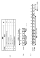
- Fig. 4 is a diagram showing examples of variables in the first method.
- the base station device 200 sets values for each of variables 1 to 5 included in Fig. 4 and notifies the terminal device 100.
- the variables indicate, for example, the positions (timing) of U slots and U symbols, or G slots and G symbols.
- the terminal device 100 can recognize the positions (timing) of U slots and U symbols, or G slots and G symbols.
- FIG. 4(A) is a diagram showing examples of variables and setting values.
- FIG. 4(B) is a diagram showing an example of a slot configuration when the setting values in FIG. 4(A) are used.
- FIG. 4(C) is a diagram showing an example of a symbol configuration when the setting values in FIG. 4(A) are used.
- Variable 1 is dl-UL-TransmissionPeriodicity, and indicates the slot period. For example, when variable 1 is 2.5, 5 slots of 2.5 msec are set as one period, as shown in FIG. 4(B). Variable 1 may be in milliseconds (msec). A millisecond may be 1/1000 of a second.
- Variable 2 is nrofDownlinkSlots, and indicates the number of D slots from the beginning of the cycle. For example, when variable 2 is set to 3, the first three slots (slots 1 to 3) become D slots, as shown in Figure 4 (B).
- Variable 4 is nrofUplinkSlots, and indicates the number of U slots from the end of the cycle. For example, when variable 4 is set to 1, the last slot (slot 5) becomes the U slot, as shown in Figure 4 (B).
- the slot configuration for each period is determined by variables 1, 2, and 4. Slots that are not set as D slots or U slots (slot 4 in FIG. 4B) become S slots or F slots. In this case, slot 4 becomes, for example, an S slot.
- Variable 3 is nrofDownlinkSymbols, and indicates the number of D symbols from the symbol next to the last symbol of the D slot.
- the last symbol of the D slot is the last symbol of slot 3, so the next symbol is the first symbol of slot 4.
- variable 3 is set to 10
- 10 symbols (symbols 1 to 10) from the first symbol of slot 4 will be D symbols, as shown in FIG. 4(C).
- Variable 5 is nrofUplinkSymbols, and indicates the number of U symbols from the symbol preceding the first symbol of the U slot.
- the first symbol of the U slot is the first symbol of slot 5, so the previous symbol is the last symbol of slot 4.
- variable 5 is set to 2
- the two symbols from the last symbol of slot 4 (symbols 13 and 14) become U symbols, as shown in FIG. 4(C).
- the symbol configuration of the S slot is determined by variables 3 and 5. Slots that are not set to D or U symbols (slot 4 in FIG. 4B) will be F symbols. In this case, symbols 11 and 12 in slot 4 will be F symbols.
- the terminal device 100 switches between uplink and downlink transmission and reception between symbols 10 and 13 in slot 4 (symbols 11 and 12). In this case, the terminal device 100 can switch, for example, at the timing of the F symbol. However, since the F symbol may be used as the U symbol or D symbol, there are cases where the switching time of the terminal device 100 is not secured. Also, in the first method, it is not possible to notify the setting of the SBFD slot (symbol).
- the setting of time resources may include, for example, the interval when switching from downlink symbols to uplink symbols, such as the guard time (Guard Period or RF Turn-around time).
- the time resource may be a slot or a symbol.
- the guard time is, for example, composed of flexible symbols.
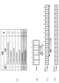
- FIG. 5 is a diagram showing an example of variables in the second method.
- the base station device 200 sets values for each of the variables 1 to 7 included in FIG. 5 and notifies the terminal device 100.
- FIG. 5(A) is a diagram showing an example of variables and set values.
- FIG. 5(B) is a diagram showing an example of a slot configuration in the case of the set values in FIG. 5(A).
- FIG. 5(C) and (D) are diagrams showing an example of a symbol configuration in the case of the set values in FIG. 5(A).
- slots 3 and 4 in FIG. 5(B) are an example of the first slot.
- variables 2 and 3 are an example of information on downlink resources.
- variables 4, 5, 6, and 7 are an example of information on uplink resources.
- variables 6 and 7 may be described as configuration information of an SBFD slot.
- variables 6 and 7 may be described as information on uplink resources in an SBFD slot.
- G indicates a guard time.
- the guard time when the guard time is in slot units, it may be called a guard slot (G slot).
- the guard time when the guard time is in symbol units, it may be called a guard symbol (G symbol).
- the G slot is a slot in which uplink and downlink signals are not transmitted or received.
- the G symbol is a symbol in which uplink and downlink signals are not transmitted or received.
- the G symbol may be described as a flexible symbol. In short, the G symbol may be any symbol different from the uplink symbol and the downlink symbol.
- Variables 1 to 5 are the same as in the first method.
- Variable 6 is nrofSBFDSlots, and indicates the number of SBFD slots from the slot including the symbol before the first U symbol included in the first U slot. If the slot period does not include a U slot, variable 6 indicates the number of SBFD slots from the last slot in the slot period. For example, when variable 6 is set to 2, the two slots before the first U symbol (first symbol of slot 5) (slots 3 and 4) become SBFD U slots, as shown in Figure 5 (B).
- Variable 7 is nrofSBFDSymbols, and indicates the number of SBFD U symbols in the U slot of the first SBFD.
- the SBFD U symbols of variable 7 are set in order from the last symbol of the U slot of the first SBFD. If there is no SBFD U slot in the slot period, the U symbols of variable 7 may be set in order from the last symbol of the slot period. If there is no SBFD U slot in the slot period, the terminal device 100 may not expect to receive variable 7. For example, when variable 7 is set to 12, as shown in FIG. 5(C), 12 symbols (symbols 3 to 14) from the end of slot 3, which is the U slot of the first SBFD, become SBFD U symbols. Note that slot 4 is an SBFD U slot, but is not the U slot of the first SBFD, so it is not affected by variable 7, and all symbols become SBFD U symbols, as shown in FIG. 5(D).
- the U symbol of the SBFD is set by variable 7.
- symbols other than the one to which the U symbol of the SBFD is set become G symbols (symbols 1 and 2 in Figure 5 (C)).
- the symbols in the SBFD slot in the SBFD can be configured by setting appropriate values to variables 6 and 7.
- the guard time can be set appropriately by setting appropriate values to variables 6 and 7.
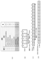
- FIG. 6 is a diagram showing an example of variables in the third method.
- the base station device 200 sets values for each of the variables 1 to 7 included in FIG. 6 and notifies the terminal device 100.
- FIG. 6(A) is a diagram showing an example of variables and set values.
- FIG. 6(B) is a diagram showing an example of a slot configuration in the case of the set values in FIG. 6(A).
- FIG. 6(C) and (D) are diagrams showing an example of a symbol configuration in the case of the set values in FIG. 6(A).
- slots 2, 3, and 4 in FIG. 6(B) are an example of the first slot.
- variables 2 and 3 are an example of information on downlink resources.
- variables 4, 5, 6, and 7 are an example of information on uplink resources.
- variables 6 and 7 may be described as configuration information of the SBFD slot.
- variables 6 and 7 may be described as information on uplink resources in the SBFD slot.
- Variables 1 to 5 are the same as in the first method.
- Variable 6 is nrofSBFDSlots, and indicates the number of SBFD slots from the slot including the symbol before the first U symbol included in the first U slot. If the slot period does not include a U slot, variable 6 indicates the number of SBFD slots from the last slot in the slot period. For example, when variable 6 is set to 2, the two slots before the first U symbol (first symbol of slot 5) (slots 3 and 4) become SBFD U slots, as shown in Figure 6 (B).
- Variable 7 is nrofSBFDSymbols, and indicates the number of SBFD U symbols from the symbol before the first symbol of the first SBFD U slot. Also, if there is no SBFD U slot within the slot period, the U symbols of variable 7 may be set in order from the last symbol of the slot period. Also, if there is no SBFD U slot within the slot period, the terminal device 100 may not expect to receive variable 7. For example, when variable 7 is set to 12, as shown in FIG. 6(B), the SBFD U symbol is set in slot 2, which includes the symbol before the first symbol of the first SBFD U slot (the first symbol of slot 3). Note that since the SBFD U symbol is set in slot 2, it is described as the U slot in FIG. 6(B). Also, as shown in FIG. 6(C), the 12 symbols from the last (symbols 3 to 14) in slot 2 are SBFD U symbols. Slots 3 and 4 are SBFD U slots, and as shown in Figure 6 (D), all symbols are SBFD U symbols.
- the U symbol of the SBFD is set by variable 7.
- symbols other than the one to which the U symbol of the SBFD is set become G symbols (symbols 1 and 2 in Figure 6 (C)).
- the symbols in the SBFD slot in the SBFD can be configured by setting appropriate values to variables 6 and 7.
- the guard time can be set appropriately by setting appropriate values to variables 6 and 7.
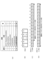
- FIG. 7 is a diagram showing an example of variables in the fourth method.
- the base station device 200 sets values for the variables 1 to 6 included in FIG. 7 and notifies the terminal device 100.
- FIG. 7(A) is a diagram showing an example of variables and set values.
- FIG. 7(B) is a diagram showing an example of a slot configuration in the case of the set values in FIG. 7(A).
- FIG. 7(C) and (D) are diagrams showing an example of a symbol configuration in the case of the set values in FIG. 6(A).
- slots 3 and 4 in FIG. 7(B) are an example of the first slot.
- variables 2 and 3 are an example of information on downlink resources.
- variables 4, 5, 6, and 7 are an example of information on uplink resources.
- variable 6 may be described as configuration information of the SBFD slot.
- variable 6 may be described as information on uplink resources in the SBFD slot.
- Variables 1 to 5 are the same as in the first method.
- Variable 6 is nrofSBFDSymbols, and indicates the number of SBFD symbols from the symbol before the first U symbol. Also, if there is no U symbol within the slot period, the U symbols of variable 6 may be set in order from the last symbol of the slot period. Also, if there is no U symbol within the slot period, the terminal device 100 does not need to expect to receive variable 6. For example, when variable 6 is set to 26, the 26 symbols before the first U symbol (the first symbol of slot 5) become SBFD U symbols. Since there are 26 symbols, as shown in FIG. 7(B), slots 3 and 4 become SBFD U slots. Then, as shown in FIG. 7(D), all symbols in slot 4 become SBFD U symbols, and as shown in FIG. 7(C), the last 12 symbols of slot 3 (symbols 3 to 14) become SBFD U symbols.
- the U symbol of the SBFD is set by variable 6.
- symbols other than the one to which the U symbol is set become G symbols (symbols 1 and 2 in Figure 7(C)).
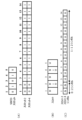
- FIG. 8 is a diagram showing an example of variables in the fifth method.
- the base station device 200 sets values for the variables 1 to 10 included in FIG. 8 and notifies the terminal device 100.
- FIG. 8(A) is a diagram showing an example of variables and set values.
- FIG. 8(B) is a diagram showing an example of a slot configuration in the case of the set values in FIG. 8(A).
- FIG. 8(C) is a diagram showing an example of a symbol configuration in the case of the set values in FIG. 8(A).
- slots 2, 3, and 4 in FIG. 8(B) are an example of the first slot.
- Variables 2 and 3 are an example of information on downlink resources.
- variables 4, 5, 9, and 10 are an example of information on uplink resources.
- variables 6 to 10 may be described as configuration information of the SBFD slot.
- variables 9 and 10 can be described as information on uplink resources in the SBFD slot.
- variables 7 and 8 can be described as information on the guard time.
- Variables 1 to 5 are the same as in the first method.
- Variable 6 is nrofGuardSlotOffset, and indicates the number of offset slots for setting the SBFD U slot from the first slot of the period. For example, when variable 6 is set to 1, as shown in FIG. 8(B), one slot (slot 1) is offset from the first slot, and the SBFD U slot is not set.
- Variable 10 is nrofSBFDSlots, and indicates the number of SBFD slots from the slot including the symbol before the first U symbol included in the first U slot. If the slot period does not include a U slot, variable 10 indicates the number of SBFD slots from the last slot in the slot period. For example, when variable 10 is set to 2, as shown in Figure 8 (B), two slots (slots 3 and 4) from the first U slot (slot 5) become SBFD U slots.
- Variable 7 is nrofGuardSymbolOffset and indicates the number of offset symbols for setting the G symbol from the first symbol in the slot before the U slot of the first SBFD. For example, when variable 7 is set to 3, as shown in Figure 8 (C), three symbols (symbols 1 to 3) are treated as an offset from the first symbol of the slot (slot 2) before the first SBFD slot (slot 3), and it remains a D symbol. Note that slot 2 is denoted as an S slot in Figure 8 (B) because it contains a mixture of SBFD U and D symbols.
- Variable 8 is nrofGuardSymbol, and indicates the number of G symbols to be set from the offset of variable 7. For example, when variable 8 is set to 2, the last two symbols (symbols 4 and 5) after the offset of 3 symbols become G symbols, as shown in Figure 8 (C).
- Variable 9 is nrofSBFDSymbols, and indicates the number of SBFD U symbols to be set before the G symbol or the first symbol of the SBFD U slot. For example, when variable 9 is set to 9, the nine symbols (symbols 6 to 14) following the last G symbol (symbol 5) become the SBFD U symbols, as shown in Figure 8 (C).
- the total number of D symbols, the number of G symbols, and the number of SBFD U symbols may be 14.
- the symbols in the SBFD slot in the SBFD can be configured by setting appropriate values to variables 6 to 10.
- the guard time can be set appropriately by setting appropriate values to variables 6 to 10.
- Fig. 9 is a diagram showing an example of variables in the sixth method.
- the base station device 200 notifies the terminal device 100 of a bitmap.
- Fig. 9(A) is a diagram showing an example of a bitmap.
- Fig. 9(B) is a diagram showing an example of a slot configuration in the case of the setting values in Fig. 9(A).
- Fig. 9(C) is a diagram showing an example of a symbol configuration in the case of the setting values in Fig. 9(A).
- the bitmap may be described as configuration information of an SBFD slot.
- the bitmap is an example of information on uplink resources.
- the example in Figure 9 is a case where the bitmap in Figure 9(A) is applied after (or at the same time as) variables 1 to 5 in the first method in Figure 4 are set.
- the bitmap in Figure 9(A) shows the position of the U symbol in SBFD, and requires, for example, the number of bits equal to the number of slots in one period multiplied by the number of symbols in one slot.
- the symbols in the SBFD slot in the SBFD can be configured by setting appropriate values in the bitmap.
- the guard time can be set appropriately by setting appropriate values in the bitmap.
- Fig. 10 is a diagram showing an example of variables in the seventh method.
- the base station device 200 notifies the terminal device 100 of a bitmap.
- Fig. 10(A) is a diagram showing an example of a bitmap.
- Fig. 10(B) is a diagram showing an example of a slot configuration in the case of the setting values in Fig. 10(A).
- Fig. 10(C) is a diagram showing an example of a symbol configuration in the case of the setting values in Fig. 10(A).
- the bitmap for the SBFD slot shown in Fig. 10(A) may be described as configuration information of the SBFD slot.
- the bitmap is an example of information on uplink resources.
- the example in Figure 10 is a case where the bitmap in Figure 10(A) is applied after (or at the same time as) variables 1 to 5 in the first method in Figure 4 are set.
- the bitmap in Figure 10(A) shows the bitmap of the slot configuration of SBFD and the position of the U symbol of SBFD.
- the slot indicated by 1 is the U slot of SBFD.
- the position of the U symbol in the SBFD in each slot is determined from the bitmaps for slots 2 and 4.
- the position of the G symbol is determined in the same way as in method 6.
- the slot configuration and symbol configuration are the same as those in FIG. 9 for the sixth method.
- the symbols in the SBFD slot in the SBFD can be configured by setting appropriate values in the bitmap.
- the guard time can be set appropriately by setting appropriate values in the bitmap.
- the SBFD slot may be the slot in which the SBFD U slot is set. Also, in all of the methods, the uplink subband configured in the SBFD U slot may use part or all of the frequency resources of each slot.
- the base station in order to execute uplink and downlink communications at the same timing within a carrier using different frequencies in the same slot, transmits information regarding the uplink resource of the uplink communication in the slot to the first terminal.
- the base station in the first slot, can perform uplink communication with the first terminal and downlink communication with the second terminal.
- the frequency resource used by the first terminal and the frequency resource used by the second terminal may be different. In other words, the base station can set SBFD.
- the U symbol of SBFD is set on, for example, the D symbol or the F symbol.
- the U symbol of SBFD is set on the D symbol, it is not determined how to handle the reception of the downlink message in the terminal device 100 at that timing. Note that, although the following description will be given using the U symbol of SBFD as an example, the same effect can be achieved even if it is replaced with the U slot of SBFD.
- the terminal device 100 is capable of receiving a downlink message if reception of the downlink message overlaps with the timing of the U symbol of the SBFD.
- the terminal device 100 receives the PDSCH on the U symbol.
- the terminal device 100 performs PDCCH Monitoring on the U symbol of the SBFD.
- a transmission/reception switching time (G symbol) may be required. Therefore, for example, when a downlink message is received on the U symbol of SBFD, the Nth symbol (N is an integer) after receiving the downlink message is set to the G symbol. This allows the terminal device 100 to secure a transmission/reception switching time.
- the N may be a constant.
- the base station device 200 may notify the terminal device 100 of the N.
- the terminal device 100 may not transmit an uplink message on the N symbols.
- the uplink message may be a PUSCH.
- the uplink message may be a PUCCH.
- the uplink message may be an SRS.
- the terminal device 100 may not expect to receive a downlink message on the N symbols.
- the downlink message may be a PDCCH.
- the downlink message may be a PDSCH.
- the downlink message may be a CSR-RS.
- the downlink message may be an SS/PBCH block.
- the terminal device 100 may receive a downlink message only when there is no data to transmit in the U symbol of the SBFD.
- the terminal device 100 may prioritize the transmission of uplink data.
- the terminal device 100 may determine whether or not to receive a downlink message on the U symbol of the SBFD for each type of downlink message. For example, the terminal device 100 performs control such that if the downlink message is a PDCCH, the downlink message is received, but if the downlink message is a PDSCH, the downlink message is not received. Note that the PDSCH and PDCCH may be reversed. Furthermore, the type of downlink message may be a type according to the data length, data priority, delay tolerance time, etc.
- the base station device 200 may change the SBFD settings and notify the terminal device 100. For example, if the base station device 200 wants the terminal device 100 to receive a downlink message on the U symbol of the SBFD, the base station device 200 may change the U symbol of the SBFD to a D symbol (returning to the setting before the U symbol of the SBFD was assigned) or change the slot or symbol configuration. The base station device 200 may also change the SBFD settings for each terminal device and notify each device individually.
- Fig. 11 is a diagram showing an example of the specifications in the second method.
- Fig. 12 is a diagram showing an example of the specifications in the third method.
- Fig. 13 is a diagram showing an example of the specifications in the fourth method.
- Fig. 14 is a diagram showing an example of the specifications in the fifth method.
- Fig. 15 is a diagram showing an example of the specifications in the sixth method.
- the base station device 200 may use each method depending on the slot or symbol configuration, etc.
- the base station device 200 may support two or more methods, for example. In this case, the base station device 200 notifies the terminal device 100 which method will be adopted. The terminal device 100 may also notify the base station device 200 of the methods it can support.
- Terminal device 110 CPU 120: Storage 121: Wireless communication program 122: SBFD execution program 130: Memory 150: Wireless communication circuit 200: Base station device 210: CPU 220: Storage 221: Wireless communication control program 222: SBFD control program 230: Memory 250: Wireless communication circuit
Landscapes
- Engineering & Computer Science (AREA)
- Signal Processing (AREA)
- Computer Networks & Wireless Communication (AREA)
- Mobile Radio Communication Systems (AREA)
Abstract
Description
第1の実施の形態について説明する。
図1は、無線通信システム10の構成例を示す図である。無線通信システム10は、基地局装置200、端末装置100を有する。無線通信システム10は、SBFDに対応する無線通信システムである。
図2は、基地局装置200の構成例を示す図である。基地局装置200は、CPU(Central Processing Unit)210、ストレージ220、メモリ230、無線通信回路250を有する。
図3は、端末装置100の構成例を表す図である。端末装置100は、CPU110、ストレージ120、メモリ130、無線通信回路150を有する。
SBFDの例について説明する。なお、以下の説明は、SBFDの一例であり、上りリンクおよび/または下りリンクの無線リソースの割当方法や、通知方法などは、以下の例に限定されない。また、本発明は、SBFD以外でも、同一タイミングや同一周波数などの1単位の無線リソースを、上りリンクおよび/または下りリンクの両方に使用する通信方式において、適用が可能である。
図4は、第1方式における変数の例を示す図である。第1方式において、基地局装置200は、図4に含まれる変数1~5にそれぞれの値を設定し、端末装置100に通知する。変数は、例えば、UスロットやUシンボル、又はGスロットやGシンボルの位置(タイミング)を示す。端末装置100は、この変数を受信することで、UスロットやUシンボル、又はGスロットやGシンボルの位置(タイミング)を認識することができる。
図5は、第2方式における変数の例を示す図である。第2方式において、基地局装置200は、図5に含まれる変数1~7にそれぞれの値を設定し、端末装置100に通知する。図5(A)は、変数及び設定値の例を示す図である。図5(B)は、図5(A)の設定値であった場合のスロット構成の例を示す図である。図5(C)及び(D)は、図5(A)の設定値であった場合のシンボル構成の例を示す図である。なお、図5(B)における、スロット3、4は、第1スロットの一例である。なお、変数2、3は、下りリンクリソースに関する情報の一例である。また、変数4、5、6、7は、上りリンクリソースに関する情報の一例である。また、変数6、7は、SBFDスロットの構成情報と記載してもよい。また、変数6、7は、SBFDスロットにおける、上りリンクリソースに関する情報と記載することもできる。 なお、以降の図において、G(Guard)は、ガード時間を示す。また、なお、ガード時間がスロット単位の場合、ガードスロット(Gスロット)と呼ぶ場合がある。また、ガード時間がシンボル単位の場合、ガードシンボル(Gシンボル)と呼ぶ場合がある。また、Gスロットは、上りリンク及び下りリンクの信号を送受信しないスロットである。さらに、Gシンボルは、上りリンク及び下りリンクの信号を送受信しないシンボルである。また、Gシンボルは、フレキシブルシンボルと記載してもよい。要するに、Gシンボルは、上りリンクシンボルと下りリンクシンボルと異なるシンボルであればよい。
図6は、第3方式における変数の例を示す図である。第3方式において、基地局装置200は、図6に含まれる変数1~7にそれぞれの値を設定し、端末装置100に通知する。図6(A)は、変数及び設定値の例を示す図である。図6(B)は、図6(A)の設定値であった場合のスロット構成の例を示す図である。図6(C)及び(D)は、図6(A)の設定値であった場合のシンボル構成の例を示す図である。なお、図6(B)における、スロット2、3、4は、第1スロットの一例である。なお、変数2、3は、下りリンクリソースに関する情報の一例である。また、変数4、5、6、7は、上りリンクリソースに関する情報の一例である。また、変数6、7は、SBFDスロットの構成情報と記載してもよい。また、変数6、7は、SBFDスロットにおける、上りリンクリソースに関する情報と記載することもできる。
図7は、第4方式における変数の例を示す図である。第4方式において、基地局装置200は、図7に含まれる変数1~6にそれぞれの値を設定し、端末装置100に通知する。図7(A)は、変数及び設定値の例を示す図である。図7(B)は、図7(A)の設定値であった場合のスロット構成の例を示す図である。図7(C)及び(D)は、図6(A)の設定値であった場合のシンボル構成の例を示す図である。なお、図7(B)における、スロット3、4は、第1スロットの一例である。なお、変数2、3は、下りリンクリソースに関する情報の一例である。また、変数4、5、6、7は、上りリンクリソースに関する情報の一例である。また、変数6は、SBFDスロットの構成情報と記載してもよい。また、変数6は、SBFDスロットにおける、上りリンクリソースに関する情報と記載することもできる。
図8は、第5方式における変数の例を示す図である。第5方式において、基地局装置200は、図8に含まれる変数1~10にそれぞれの値を設定し、端末装置100に通知する。図8(A)は、変数及び設定値の例を示す図である。図8(B)は、図8(A)の設定値であった場合のスロット構成の例を示す図である。図8(C)は、図8(A)の設定値であった場合のシンボル構成の例を示す図である。なお、図8(B)における、スロット2、3、4は、第1スロットの一例である。変数2、3は、下りリンクリソースに関する情報の一例である。また、変数4、5、9、10は、上りリンクリソースに関する情報の一例である。また、変数6~10は、SBFDスロットの構成情報と記載してもよい。また、変数9、10は、SBFDスロットにおける、上りリンクリソースに関する情報と記載することもできる。また、変数7、8は、ガード時間に関する情報と記載することもできる。
図9は、第6方式における変数の例を示す図である。第6方式において、基地局装置200は、ビットマップを端末装置100に通知する。図9(A)は、ビットマップの例を示す図である。図9(B)は、図9(A)の設定値であった場合のスロット構成の例を示す図である。図9(C)は、図9(A)の設定値であった場合のシンボル構成の例を示す図である。なお、ビットマップを、SBFDスロットの構成情報と記載してもよい。なお、ビットマップは、上りリソースに関する情報の一例である。
図10は、第7方式における変数の例を示す図である。基地局装置200は、ビットマップを端末装置100に通知する。図10(A)は、ビットマップの例を示す図である。図10(B)は、図10(A)の設定値であった場合のスロット構成の例を示す図である。図10(C)は、図10(A)の設定値であった場合のシンボル構成の例を示す図である。なお、図10(A)に記載されたSBFDスロットに対するビットマップを、SBFDスロットの構成情報と記載してもよい。なお、ビットマップは、上りリソースに関する情報の一例である。
第2の実施の形態について説明する。SBFDのUシンボルは、例えば、DシンボルやFシンボル上に設定される。例えば、Dシンボル上にSBFDのUシンボルが設定された場合、当該タイミングにおいて、端末装置100において下りリンクメッセージの受信をどのように扱うかについては決定していない。なお、以下、SBFDのUシンボルを例に説明するが、SBFDのUスロットと置き換えても、同様の効果を奏する。
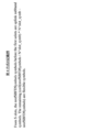
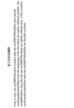
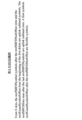
各実施の形態における、3GPPへの仕様書の記載について説明する。図11は、第2方式における仕様書の記載例を示す図である。図12は、第3方式における仕様書の記載例を示す図である。図13は、第4方式における仕様書の記載例を示す図である。図14は、第5方式における仕様書の記載例を示す図である。図15は、第6方式における仕様書の記載例を示す図である。
110 :CPU
120 :ストレージ
121 :無線通信プログラム
122 :SBFD実行プログラム
130 :メモリ
150 :無線通信回路
200 :基地局装置
210 :CPU
220 :ストレージ
221 :無線通信制御プログラム
222 :SBFD制御プログラム
230 :メモリ
250 :無線通信回路
Claims (7)
- キャリア内の第1スロットにおける異なる周波数を用いて、上りリンク通信及び下りリンクの通信を同一タイミングで実行する第1通信に対応する無線通信システムにおける基地局装置であって、
前記第1通信に関する第1情報を端末装置に通知する通知部と、
前記第1情報に応じて、前記第1スロットで前記端末装置と前記上りリンク通信を行う通信部とを有し、
前記第1情報は、前記上りリンク通信の上りリンクリソースに関する情報を含む
基地局装置。 - 前記第1情報は、前記第1スロットにおいて、上りリンク通信を行うシンボル数を示す情報を含む、
請求項1に記載の基地局装置。 - 前記第1情報は、前記上りリンクリソース及び下りリンクリソースとして使用しないリソースに関する情報を含む
請求項1に記載の基地局装置。 - 前記第1情報は、前記上りリンクリソース及び前記下りリンクリソースとして使用しないシンボルであるガードシンボルのタイミングに関する情報を含む
請求項3記載の基地局装置。 - 前記第1情報は、前記第1通信において、前記上りリンクリソースとして使用する上りリンクシンボルのタイミングに関する情報を含み、
前記端末装置は、前記上りリンクシンボルを含むスロット内の前記上りリンクシンボル及び下りリンクリソースとして使用する下りリンクシンボル以外のシンボルを、上りリンクリソース及び下りリンクリソースとして使用しない
請求項1記載の基地局装置。 - キャリア内の第1スロットにおける異なる周波数を用いて、上りリンク通信及び下りリンクの通信を同一タイミングで実行する第1通信に対応する基地局装置を無線通信システムにおける端末装置であって、
前記第1通信に関する第1情報を前記基地局装置から受信する受信部と、
前記第1情報に応じて、前記第1スロットで前記基地局装置と前記上りリンク通信を行う端末通信部とを有し、
前記第1情報は、前記上りリンク通信の上りリンクリソースに関する情報を含む
端末装置。 - キャリア内の第1スロットにおける異なる周波数を用いて、上りリンク通信及び下りリンクの通信を同一タイミングで実行する第1通信に対応する無線通信システムであって、
基地局装置は、前記第1通信に関する第1情報を端末装置に通知し、
前記端末装置は、前記第1情報を受信し、
前記基地局装置及び前記端末装置は、前記第1情報に応じて、前記第1スロットで前記上りリンク通信を行い、
前記第1情報は、前記上りリンク通信の上りリンクリソースに関する情報を含む
無線通信システム。
Priority Applications (3)
| Application Number | Priority Date | Filing Date | Title |
|---|---|---|---|
| JP2024576010A JPWO2024166316A1 (ja) | 2023-02-09 | 2023-02-09 | |
| PCT/JP2023/004415 WO2024166316A1 (ja) | 2023-02-09 | 2023-02-09 | 基地局装置、端末装置、及び無線通信システム |
| US19/294,499 US20260019204A1 (en) | 2023-02-09 | 2025-08-08 | Base station device, terminal device, and wireless communication system |
Applications Claiming Priority (1)
| Application Number | Priority Date | Filing Date | Title |
|---|---|---|---|
| PCT/JP2023/004415 WO2024166316A1 (ja) | 2023-02-09 | 2023-02-09 | 基地局装置、端末装置、及び無線通信システム |
Related Child Applications (1)
| Application Number | Title | Priority Date | Filing Date |
|---|---|---|---|
| US19/294,499 Continuation US20260019204A1 (en) | 2023-02-09 | 2025-08-08 | Base station device, terminal device, and wireless communication system |
Publications (1)
| Publication Number | Publication Date |
|---|---|
| WO2024166316A1 true WO2024166316A1 (ja) | 2024-08-15 |
Family
ID=92262140
Family Applications (1)
| Application Number | Title | Priority Date | Filing Date |
|---|---|---|---|
| PCT/JP2023/004415 Ceased WO2024166316A1 (ja) | 2023-02-09 | 2023-02-09 | 基地局装置、端末装置、及び無線通信システム |
Country Status (3)
| Country | Link |
|---|---|
| US (1) | US20260019204A1 (ja) |
| JP (1) | JPWO2024166316A1 (ja) |
| WO (1) | WO2024166316A1 (ja) |
Citations (1)
| Publication number | Priority date | Publication date | Assignee | Title |
|---|---|---|---|---|
| JP2020518173A (ja) * | 2017-04-21 | 2020-06-18 | アップル インコーポレイテッドApple Inc. | フレキシブルスロットフォーマットインジケータを利用するための装置、システム、及び方法 |
-
2023
- 2023-02-09 WO PCT/JP2023/004415 patent/WO2024166316A1/ja not_active Ceased
- 2023-02-09 JP JP2024576010A patent/JPWO2024166316A1/ja active Pending
-
2025
- 2025-08-08 US US19/294,499 patent/US20260019204A1/en active Pending
Patent Citations (1)
| Publication number | Priority date | Publication date | Assignee | Title |
|---|---|---|---|---|
| JP2020518173A (ja) * | 2017-04-21 | 2020-06-18 | アップル インコーポレイテッドApple Inc. | フレキシブルスロットフォーマットインジケータを利用するための装置、システム、及び方法 |
Non-Patent Citations (2)
| Title |
|---|
| CMCC: "Discussion on subband non-overlapping full duplex", 3GPP DRAFT; R1-2209336, 3RD GENERATION PARTNERSHIP PROJECT (3GPP), MOBILE COMPETENCE CENTRE ; 650, ROUTE DES LUCIOLES ; F-06921 SOPHIA-ANTIPOLIS CEDEX ; FRANCE, vol. RAN WG1, no. e-Meeting; 20221010 - 20221019, 30 September 2022 (2022-09-30), Mobile Competence Centre ; 650, route des Lucioles ; F-06921 Sophia-Antipolis Cedex ; France, XP052277255 * |
| MODERATOR (CATT): "Summary #4 of subband non-overlapping full duplex", 3GPP DRAFT; R1-2210317, 3RD GENERATION PARTNERSHIP PROJECT (3GPP), MOBILE COMPETENCE CENTRE ; 650, ROUTE DES LUCIOLES ; F-06921 SOPHIA-ANTIPOLIS CEDEX ; FRANCE, vol. RAN WG1, no. e-Meeting; 20221010 - 20221019, 20 October 2022 (2022-10-20), Mobile Competence Centre ; 650, route des Lucioles ; F-06921 Sophia-Antipolis Cedex ; France, XP052259785 * |
Also Published As
| Publication number | Publication date |
|---|---|
| JPWO2024166316A1 (ja) | 2024-08-15 |
| US20260019204A1 (en) | 2026-01-15 |
Similar Documents
| Publication | Publication Date | Title |
|---|---|---|
| US10708832B2 (en) | Deactivation method and apparatus for a secondary cell and communications system | |
| US11006270B2 (en) | Method and device for use in reporting terminal capability | |
| TWI674811B (zh) | 用於行動通訊系統之使用者裝置及基地台 | |
| JP7706543B2 (ja) | 送信切り替え方法およびその関連装置 | |
| EP3739922B1 (en) | User equipment capability report method and resource scheduling method, user equipment, and network device | |
| CN113785622A (zh) | 用于传送具有偏移的数据通信的方法和装置 | |
| US11595964B2 (en) | Method and device for determining information domain value in DCI | |
| US11424964B2 (en) | Sounding reference signal receiving method, apparatus, and system | |
| RU2756849C1 (ru) | Способ связи, сетевое устройство и оконечное устройство | |
| JP6180476B2 (ja) | 単一送受信器を用いた複数の時分割複信リンクの同時使用 | |
| RU2592402C2 (ru) | Системы и способы для планирования многоканального входа-многоканального выхода (mimo) высокоскоростного пакетного доступа по нисходящему каналу (hsdpa) пилотных каналов | |
| JP7597832B2 (ja) | ビーム指示方法、ネットワーク側機器と端末 | |
| EP4301069A1 (en) | Data transmission method and apparatus | |
| JP7846410B2 (ja) | 第1無線通信装置及び第2無線通信装置 | |
| KR102908214B1 (ko) | 다중 pdcch 반복 전송 시나리오에 대한 cpu 점유 시간 결정 방법 및 장치, 저장 매체 및 단말 | |
| WO2024166316A1 (ja) | 基地局装置、端末装置、及び無線通信システム | |
| EP3245831B1 (en) | Resource scheduling of uplink resources | |
| US20240008016A1 (en) | Communication method and apparatus | |
| CN110034898A (zh) | 一种参考信号传输方法及装置 | |
| CN119485553A (zh) | 终端的发射机状态确定方法、系统以及基站和终端 | |
| US20250024443A1 (en) | First wireless communication device and second wireless communication device | |
| WO2023017686A1 (ja) | 無線通信の遅延を低減する端末装置、制御方法、及びプログラム | |
| CN121400027A (zh) | 灵活帧结构 | |
| WO2024062616A1 (ja) | 基地局装置、端末装置、及び無線通信システム | |
| HK40121639A (zh) | 带宽部分切换 |
Legal Events
| Date | Code | Title | Description |
|---|---|---|---|
| 121 | Ep: the epo has been informed by wipo that ep was designated in this application |
Ref document number: 23921147 Country of ref document: EP Kind code of ref document: A1 |
|
| ENP | Entry into the national phase |
Ref document number: 2024576010 Country of ref document: JP Kind code of ref document: A |
|
| WWE | Wipo information: entry into national phase |
Ref document number: 2024576010 Country of ref document: JP |
|
| NENP | Non-entry into the national phase |
Ref country code: DE |
|
| 122 | Ep: pct application non-entry in european phase |
Ref document number: 23921147 Country of ref document: EP Kind code of ref document: A1 |