WO2024166249A1 - 端末及び通信方法 - Google Patents
端末及び通信方法 Download PDFInfo
- Publication number
- WO2024166249A1 WO2024166249A1 PCT/JP2023/004174 JP2023004174W WO2024166249A1 WO 2024166249 A1 WO2024166249 A1 WO 2024166249A1 JP 2023004174 W JP2023004174 W JP 2023004174W WO 2024166249 A1 WO2024166249 A1 WO 2024166249A1
- Authority
- WO
- WIPO (PCT)
- Prior art keywords
- channel bandwidth
- terminal
- supported
- base station
- channel
- Prior art date
- Legal status (The legal status is an assumption and is not a legal conclusion. Google has not performed a legal analysis and makes no representation as to the accuracy of the status listed.)
- Ceased
Links
Images


Classifications
-
- H—ELECTRICITY
- H04—ELECTRIC COMMUNICATION TECHNIQUE
- H04W—WIRELESS COMMUNICATION NETWORKS
- H04W72/00—Local resource management
- H04W72/02—Selection of wireless resources by user or terminal
-
- H—ELECTRICITY
- H04—ELECTRIC COMMUNICATION TECHNIQUE
- H04W—WIRELESS COMMUNICATION NETWORKS
- H04W72/00—Local resource management
- H04W72/04—Wireless resource allocation
- H04W72/044—Wireless resource allocation based on the type of the allocated resource
- H04W72/0457—Variable allocation of band or rate
Definitions
- the present invention relates to a terminal and a communication method in a wireless communication system.
- Non-Patent Document 1 For NR (New Radio) (also known as “5G”), the successor system to LTE (Long Term Evolution), technologies are being considered that meet the requirements of a large-capacity system, high data transmission speed, low latency, simultaneous connection of many terminals, low cost, and low power consumption (for example, Non-Patent Document 1).
- the present invention has been made in consideration of the above points, and aims to determine a radio frame structure according to a frequency band in a wireless communication system.
- a terminal has a control unit that determines a channel bandwidth to be supported in a specific frequency band, and a communication unit that applies the determined channel bandwidth to communicate in the specific frequency band, and the control unit determines the channel bandwidth from a certain frequency width range, determines the channel bandwidth less than a certain frequency width, or determines the channel bandwidth more than a certain frequency width.
- the disclosed technology makes it possible to determine a radio frame structure according to a frequency band in a wireless communication system.
- FIG. 1 is a diagram illustrating an example of the configuration of a wireless communication system.
- FIG. 2 is a diagram illustrating an example of a new frequency band according to an embodiment of the present invention.
- FIG. 11 is a sequence diagram for explaining an example of operation in a new frequency band according to an embodiment of the present invention.
- FIG. 2 is a diagram illustrating an example of a functional configuration of a base station 10 according to an embodiment of the present invention.
- FIG. 2 is a diagram illustrating an example of a functional configuration of a terminal 20 according to an embodiment of the present invention.
- 2 is a diagram illustrating an example of a hardware configuration of a base station 10 or a terminal 20 according to an embodiment of the present invention.
- FIG. 2 is a diagram showing an example of the configuration of a vehicle 2001 according to an embodiment of the present invention.
- LTE Long Term Evolution
- NR NR
- SS Synchronization signal
- PSS Primary SS
- SSS Secondary SS
- PBCH Physical broadcast channel
- PRACH Physical random access channel
- PDCCH Physical Downlink Control Channel
- PDSCH Physical Downlink Shared Channel
- PUCCH Physical Uplink Control Channel
- PUSCH Physical Uplink Shared Channel
- NR corresponds to NR-SS, NR-PSS, NR-SSS, NR-PBCH, NR-PRACH, etc.
- NR- even if a signal is used in NR, it is not necessarily specified as "NR-".
- the duplex method may be a TDD (Time Division Duplex) method, an FDD (Frequency Division Duplex) method, or another method (e.g., Flexible Duplex, etc.).
- TDD Time Division Duplex
- FDD Frequency Division Duplex
- another method e.g., Flexible Duplex, etc.
- radio parameters and the like when radio parameters and the like are “configured,” it may mean that predetermined values are pre-configured, or that radio parameters notified from the base station 10 or the terminal 20 are configured.
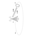
- FIG. 1 is a diagram showing a configuration example (1) of a wireless communication system in an embodiment of the present invention.
- the wireless communication system in the embodiment of the present invention includes a base station 10 and a terminal 20.
- FIG. 1 shows one base station 10 and one terminal 20, this is an example, and there may be multiple of each.
- the base station 10 is a communication device that provides one or more cells and performs wireless communication with the terminal 20.
- the physical resources of a wireless signal are defined in the time domain and the frequency domain, where the time domain may be defined by the number of OFDM (Orthogonal Frequency Division Multiplexing) symbols, and the frequency domain may be defined by the number of subcarriers or the number of resource blocks.
- the base station 10 transmits a synchronization signal and system information to the terminal 20.
- the synchronization signal is, for example, NR-PSS and NR-SSS.
- the system information is, for example, transmitted by NR-PBCH and is also called broadcast information.
- the synchronization signal and system information may be called SSB (SS/PBCH block). As shown in FIG.
- the base station 10 transmits a control signal or data to the terminal 20 in DL (Downlink) and receives a control signal or data from the terminal 20 in UL (Uplink). Both the base station 10 and the terminal 20 are capable of transmitting and receiving signals by performing beamforming. In addition, both the base station 10 and the terminal 20 can apply MIMO (Multiple Input Multiple Output) communication to DL or UL. In addition, both the base station 10 and the terminal 20 may communicate via a secondary cell (SCell: Secondary Cell) and a primary cell (PCell: Primary Cell) using CA (Carrier Aggregation). Furthermore, the terminal 20 may communicate via a primary cell of the base station 10 and a primary secondary cell group cell (PSCell: Primary SCG Cell) of another base station 10 using DC (Dual Connectivity).
- SCell Secondary Cell
- PCell Primary Cell
- CA Carrier Aggregation
- the terminal 20 may communicate via a primary cell of the base station 10 and a primary secondary cell group cell (PSCell: Primary SCG Cell) of another base station 10
- the terminal 20 is a communication device equipped with a wireless communication function, such as a smartphone, a mobile phone, a tablet, a wearable terminal, or a communication module for M2M (Machine-to-Machine). As shown in FIG. 1, the terminal 20 receives control signals or data from the base station 10 in DL and transmits control signals or data to the base station 10 in UL, thereby utilizing various communication services provided by the wireless communication system. The terminal 20 also receives various reference signals transmitted from the base station 10, and performs measurement of the propagation path quality based on the reception results of the reference signals.
- M2M Machine-to-Machine
- the terminal 20 is capable of performing carrier aggregation, which bundles multiple cells (multiple CCs (Component Carriers)) together to communicate with the base station 10.
- carrier aggregation one PCell (Primary cell) and one or more SCells (Secondary cells) are used.
- a PUCCH-SCell having a PUCCH may also be used.
- FIG. 2 is a diagram showing an example of a new frequency band according to an embodiment of the present invention.
- the frequency band between FR1 (Frequency Range 1) and FR2 (Frequency Range 2) is assumed as a candidate for the new frequency band.
- frequency bands of 7.025-7.125 GHz and 10.0 GHz-10.5 GHz may be newly supported.
- the frequency band may be called, for example, FR3 (Frequency Range 3), or may be called by another name.
- frequency bands beyond FR2 are envisioned as candidates for new frequency bands.
- a new frequency band of 72-100 GHz or higher may be supported.
- Such frequency bands may be called, for example, FR4 (Frequency Range 4), or may have another name.
- FR3 is expected to be more likely to be supported, and is being considered for use in IMT at the World Radiocommunication Conference (WRC-23). FR3 also has a lower frequency than FR2, so it is considered more practical than FR2.
- frame structure When supporting a new frequency band, several basic functions need to be determined. For example, frame structure, initial access procedure, physical layer control, scheduling specifications, HARQ (Hybrid automatic repeat request) specifications, MIMO specifications, etc. need to be determined.
- HARQ Hybrid automatic repeat request
- the frame structure to be determined includes a channel bandwidth, a waveform, and a subcarrier spacing. Therefore, the channel bandwidth, the waveform, or the subcarrier spacing may be determined as described below.
- FIG. 3 is a sequence diagram for explaining an example of operation in a new frequency band according to an embodiment of the present invention.
- terminal 20 determines the channel bandwidth, waveform and/or subcarrier spacing to be applied in FR3.
- terminal 20 performs communication in FR3 by applying the determined channel bandwidth, waveform and/or subcarrier spacing.
- the set of channel bandwidths supported in FR3 may be 1)-3) as shown below.
- It may be a set of channel bandwidths that are the same as FR1. This reduces the impact on specifications and implementation.
- FR1 and/or FR2 may have a different set of channel bandwidths, allowing optimized channel bandwidths to be used.
- the channel bandwidth may be at least one of 1)-3) shown below.
- It may be in the range of 100 MHz to 400 Hz. For example, it may be ⁇ 400, 300, 200, 190, 180, 175, 170, 160, 150, 140, 130, 125, 120, 110, 100 ⁇ [MHz]. This allows a balance between the throughput of a wide bandwidth and the frequency multiplexing capacity of a narrow bandwidth.
- It may be 100 MHz or less.
- the same channel bandwidth as that supported by FR1 may be supported. This allows flexible coexistence between different operators.
- It may be 400 MHz or more. For example, it may be 500 MHz. This allows for the expectation of high throughput due to the wide bandwidth.
- the channel bandwidths supported in FR3 may be one or more bandwidths greater than 100 MHz and one or more bandwidths less than or equal to 100 MHz.
- the channel bandwidths supported in FR3 may be one or more bandwidths less than 50 MHz and one or more bandwidths equal to or greater than 50 MHz.
- the channel bandwidths supported in FR3 may be some or all of 1)-3) shown below.
- the maximum channel bandwidth supported in FR3 may be some or all of 1)-3) shown below.
- 100 MHz which allows flexible coexistence between different operators.
- 400 MHz which allows a throughput equivalent to that of FR2 to be achieved.
- the minimum channel bandwidth supported in FR3 may be some or all of 1)-4) below.
- the maximum and/or minimum channel bandwidth supported in FR3 may vary depending on the band.
- a maximum and/or minimum channel bandwidth of 5 MHz to 100 MHz may be supported, and in the 10.0 GHz to 10.5 GHz band, a maximum and/or minimum channel bandwidth of 20 MHz to 200 MHz may be supported.
- the number of channel bandwidth candidates supported in FR3 may be some or all of 1)-3) shown below.
- FR3 whether support for channel bandwidth is mandatory or optional may be defined as follows:
- the required channel bandwidth supported in FR3 may be any of 1)-3) shown below.
- FR1 The same set of support as FR1 may be required. 2) The same set of support as FR2 may be required. 3) A different set of support may be required than FR1 and/or FR2.
- a channel bandwidth defined or supported in FR3 is mandatory or optional may be specified as one of 1)-9) below.
- N may be defined in the specification and may be, for example, 1, 2, 3, 4, or 5.
- X may be defined in the specifications, and may be, for example, 5, 10, 20, 30, 40, 50, or 100.
- N may be defined in the specification, and may be, for example, 1, 2, 3, 4, or 5.
- X may be defined in the specifications, and may be, for example, 5, 10, 20, 30, 40, 50, or 100.
- the specific channel bandwidth may be flexibly set, such as small, medium, or large.
- the specific channel bandwidth may be a channel bandwidth of less than 50 MHz, as in FR1, a channel bandwidth of 50 MHz to 100 MHz specific to FR3, or a channel bandwidth of more than 100 MHz, as in FR2.
- Support for all channel bandwidths specified in FR3 may be optional.
- the value of the channel bandwidth may not be restricted, and a minimum number of channel bandwidths that must be supported may be specified. For example, support of at least one channel bandwidth may be required, or support of at least three channel bandwidths may be required.
- the channel bandwidth value may not be restricted, and a maximum number of channel bandwidths that must be supported may be specified. For example, support for a maximum of five channel bandwidths may be required.
- CP-OFDM Cyclic-Prefix OFDM
- DFT-S-OFDM Discrete Fourier Transform - Spread - OFDM
- FR3 may support CP-OFDM for the downlink, and CP-OFDM and DFT-S-OFDM for the uplink, just like FR1 and FR2.
- FR3 may support different waveforms than FR1 or FR2.
- Table 1 shows examples of waveforms supported in FR3.
- CP-OFDM may be supported in DL and UL
- DFT-S-OFDM may be supported in UL. This allows for the same implementation as FR1 and FR2.
- CP-OFDM may be supported in DL and UL
- DFT-S-OFDM may be supported in DL and UL. Supporting DFT-S-OFDM in DL can expand coverage.
- CP-OFDM may be supported in both DL and UL. This reduces the implementation burden by supporting a single waveform.
- CP-OFDM may be supported in DL and UL
- DFT-S-OFDM may be supported in DL.
- CP-OFDM may be supported in DL and DFT-S-OFDM may be supported in DL and UL.
- CP-OFDM may be supported in the DL and DFT-S-OFDM in the UL.
- CP-OFDM may be supported in the UL and DFT-S-OFDM may be supported in both the DL and UL.
- CP-OFDM may be supported in the UL and DFT-S-OFDM may be supported in the DL.
- DFT-S-OFDM may be supported in DL and UL as shown in Alt-9 of Table 1.
- the minimum guard band or number of RBs supported may be any of 1)-3) shown below.
- the minimum guard band of the same channel bandwidth to which the same SCS is applied may be the same. This allows the implementation of the spectral filter in FR1 and/or FR2 to be reused.
- the minimum guard band may be wider than the minimum guard band of the same channel bandwidth to which the same SCS is applied. This allows for simpler implementation than implementing a spectral filter in FR1 and/or FR2.
- the minimum guard band may be narrower than the minimum guard band of the same channel bandwidth to which the same SCS is applied. This can improve resource usage efficiency.
- guard bands other than the minimum guard band may be defined.
- a terminal 20 capable of achieving the guard band may be a terminal 20 that has higher functionality than a terminal 20 that achieves only the minimum guard band, and that generates a high-quality signal with reduced interference with adjacent bands while achieving the same band.
- CP-OFDM or DFT-S-OFDM is supported for DL or UL may be specified as either 1) or 2) below.
- All terminals 20 that support FR3 may support all waveforms for DL and UL. This allows for more flexible operation.
- a terminal 20 that supports FR3 does not need to support all waveforms for DL or UL. This reduces the implementation load of the terminal.
- Table 2 shows examples of SCS supported in FR3.
- the supported SCS may be 15 kHz, 30 kHz, and 60 kHz. This allows for an implementation similar to FR1.
- the supported SCS may be 60 kHz, 120 kHz, and 240 kHz. This allows for a similar implementation to FR2.
- the supported SCS may be 30 kHz, 60 kHz, and 120 kHz. This allows for the same implementation as FR2. This allows for the use of SCS combinations optimized for FR3.
- the supported SCS may be 30 kHz and 60 kHz. This allows for an implementation similar to FR1.
- the supported SCS may be 60 kHz and 120 kHz. This allows for a similar implementation to FR2.
- Table 3 shows examples of combinations of maximum channel bandwidth and SCS in NR.
- the maximum number of RBs is approximately 270.
- the maximum number of RBs is 270.
- the maximum number of RBs is 273.
- the maximum number of RBs is 135.
- the maximum number of RBs is 264.
- the SCS is 120 kHz and the channel bandwidth is 400 MHz in FR2, the maximum number of RBs is 264.
- the maximum channel bandwidth may be set to twice the value shown in Table 3. That is, it may be set to 100 MHz for SCS 15 kHz, 200 MHz for SCS 30 kHz, 200 MHz or 400 MHz for SCS 60 kHz, and 800 MHz for SCS 120 kHz.
- SCS may be supported as follows: 1)-3).
- All SCSs may be mandatory to be supported. 2) The number of mandatory supported SCSs may be limited. 3) Support of N SCSs is mandatory, in ascending order from the smallest SCS, where N may be 1 or 2. 4) Support for N SCSs is mandatory, starting from the maximum SCS, where N may be 1 or 2.
- the supported SCS may also be determined depending on the maximum channel bandwidth supported.
- SCS 15 KHz may be supported.
- SCS 30 KHz may be supported.
- SCS 60 KHz may be supported.
- the number of supported FFT points may be determined depending on the maximum channel bandwidth.
- the above-described embodiment allows the terminal 20 to determine the radio frame structure, such as the channel bandwidth, waveform, and subcarrier spacing, according to the frequency band, and to communicate efficiently.
- the base station 10 and the terminal 20 include functions for implementing the above-mentioned embodiments. However, the base station 10 and the terminal 20 may each include only a part of the functions in the embodiments.
- Fig. 4 is a diagram showing an example of the functional configuration of the base station 10 in the embodiment of the present invention.
- the base station 10 has a transmitting unit 110, a receiving unit 120, a setting unit 130, and a control unit 140.
- the functional configuration shown in Fig. 4 is merely an example.
- the names of the functional divisions and functional units may be any as long as they can execute the operations related to the embodiment of the present invention.
- the transmitting unit 110 has a function of generating a signal to be transmitted to the terminal 20 side and transmitting the signal wirelessly.
- the transmitting unit 110 also transmits inter-network node messages to other network nodes.
- the receiving unit 120 has a function of receiving various signals transmitted from the terminal 20 and acquiring, for example, information of a higher layer from the received signals.
- the transmitting unit 110 also has a function of transmitting NR-PSS, NR-SSS, NR-PBCH, DL/UL control signals, etc. to the terminal 20.
- the receiving unit 120 also receives inter-network node messages from other network nodes.
- the setting unit 130 stores preset setting information and various setting information to be transmitted to the terminal 20.
- the contents of the setting information include, for example, information related to the channel bandwidth, waveform, and/or subcarrier spacing.
- the control unit 140 performs control to realize the functions described in the embodiments. Furthermore, as described in the embodiments, the control unit 140 performs control related to the channel bandwidth, waveform and/or subcarrier spacing.
- the functional unit related to signal transmission in the control unit 140 may be included in the transmitting unit 110, and the functional unit related to signal reception in the control unit 140 may be included in the receiving unit 120.
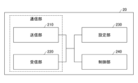
- Fig. 5 is a diagram showing an example of a functional configuration of the terminal 20 in the embodiment of the present invention.
- the terminal 20 has a transmitting unit 210, a receiving unit 220, a setting unit 230, and a control unit 240.
- the functional configuration shown in Fig. 5 is merely an example.
- the names of the functional divisions and functional units may be any as long as they can execute the operations related to the embodiment of the present invention.
- the transmitter 210 creates a transmission signal from the transmission data and transmits the transmission signal wirelessly.
- the receiver 220 wirelessly receives various signals and acquires higher layer signals from the received physical layer signals.
- the receiver 220 also has a function of receiving NR-PSS, NR-SSS, NR-PBCH, DL/UL/SL control signals, etc. transmitted from the base station 10.
- the transmitter 210 transmits PSCCH (Physical Sidelink Control Channel), PSSCH (Physical Sidelink Shared Channel), PSDCH (Physical Sidelink Discovery Channel), PSBCH (Physical Sidelink Broadcast Channel), etc. to another terminal 20 as D2D communication, and the receiver 220 receives PSCCH, PSSCH, PSDCH, PSBCH, etc. from the other terminal 20.
- PSCCH Physical Sidelink Control Channel
- PSSCH Physical Sidelink Shared Channel
- PSDCH Physical Sidelink Discovery Channel
- PSBCH Physical Sidelink Broadcast Channel
- the setting unit 230 stores various setting information received from the base station 10 by the receiving unit 220.
- the setting unit 230 also stores setting information that is set in advance.
- the contents of the setting information include, for example, information related to the channel bandwidth, waveform, and/or subcarrier spacing.
- the control unit 240 performs control to realize the functions described in the embodiments. Furthermore, the control unit 240 performs control related to the channel bandwidth, waveform and/or subcarrier spacing as described in the embodiments.
- the functional unit related to signal transmission in the control unit 240 may be included in the transmitting unit 210, and the functional unit related to signal reception in the control unit 240 may be included in the receiving unit 220.
- each functional block may be realized using one device that is physically or logically coupled, or may be realized using two or more devices that are physically or logically separated and directly or indirectly connected (for example, using wires, wirelessly, etc.).
- the functional block may be realized by combining the one device or the multiple devices with software.
- Functions include, but are not limited to, judgement, determination, judgment, calculation, computation, processing, derivation, investigation, search, confirmation, reception, transmission, output, access, resolution, selection, selection, establishment, comparison, assumption, expectation, regarding, broadcasting, notifying, communicating, forwarding, configuring, reconfiguring, allocating, mapping, and assignment.
- a functional block (component) that performs the transmission function is called a transmitting unit or transmitter.
- the base station 10, terminal 20, etc. in one embodiment of the present disclosure may function as a computer that performs processing of the wireless communication method of the present disclosure.
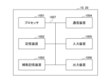
- FIG. 6 is a diagram showing an example of the hardware configuration of the base station 10 and terminal 20 in one embodiment of the present disclosure.
- the above-mentioned base station 10 and terminal 20 may be physically configured as a computer device including a processor 1001, a storage device 1002, an auxiliary storage device 1003, a communication device 1004, an input device 1005, an output device 1006, a bus 1007, etc.
- the term "apparatus" can be interpreted as a circuit, device, unit, etc.
- the hardware configuration of the base station 10 and the terminal 20 may be configured to include one or more of the devices shown in the figure, or may be configured to exclude some of the devices.
- the functions of the base station 10 and the terminal 20 are realized by loading specific software (programs) onto hardware such as the processor 1001 and the storage device 1002, causing the processor 1001 to perform calculations, control communications by the communication device 1004, and control at least one of the reading and writing of data in the storage device 1002 and the auxiliary storage device 1003.
- the processor 1001 for example, operates an operating system to control the entire computer.
- the processor 1001 may be configured as a central processing unit (CPU) including an interface with peripheral devices, a control device, an arithmetic unit, registers, etc.
- CPU central processing unit
- control unit 140, control unit 240, etc. may be realized by the processor 1001.
- the processor 1001 reads out a program (program code), software module, data, etc. from at least one of the auxiliary storage device 1003 and the communication device 1004 to the storage device 1002, and executes various processes according to the program.
- the program is a program that causes a computer to execute at least a part of the operations described in the above-mentioned embodiment.
- the control unit 140 of the base station 10 shown in FIG. 4 may be stored in the storage device 1002 and realized by a control program that runs on the processor 1001.
- the control unit 240 of the terminal 20 shown in FIG. 5 may be stored in the storage device 1002 and realized by a control program that runs on the processor 1001.
- the processor 1001 may be implemented by one or more chips.
- the program may be transmitted from a network via a telecommunication line.
- the storage device 1002 is a computer-readable recording medium and may be composed of, for example, at least one of a ROM (Read Only Memory), an EPROM (Erasable Programmable ROM), an EEPROM (Electrically Erasable Programmable ROM), a RAM (Random Access Memory), etc.
- the storage device 1002 may also be called a register, a cache, a main memory, etc.
- the storage device 1002 can store executable programs (program codes), software modules, etc. for implementing a communication method relating to one embodiment of the present disclosure.
- the auxiliary storage device 1003 is a computer-readable recording medium, and may be, for example, at least one of an optical disk such as a CD-ROM (Compact Disc ROM), a hard disk drive, a flexible disk, a magneto-optical disk (e.g., a compact disk, a digital versatile disk, a Blu-ray (registered trademark) disk), a smart card, a flash memory (e.g., a card, a stick, a key drive), a floppy (registered trademark) disk, a magnetic strip, etc.
- the above-mentioned storage medium may be, for example, a database, a server, or other suitable medium that includes at least one of the storage device 1002 and the auxiliary storage device 1003.
- the communication device 1004 is hardware (transmitting/receiving device) for communicating between computers via at least one of a wired network and a wireless network, and is also referred to as, for example, a network device, a network controller, a network card, a communication module, etc.
- the communication device 1004 may be configured to include a high-frequency switch, a duplexer, a filter, a frequency synthesizer, etc., to realize at least one of, for example, Frequency Division Duplex (FDD) and Time Division Duplex (TDD).
- FDD Frequency Division Duplex
- TDD Time Division Duplex
- the transmitting/receiving antenna, an amplifier unit, a transmitting/receiving unit, a transmission path interface, etc. may be realized by the communication device 1004.
- the transmitting/receiving unit may be implemented as a transmitting unit or a receiving unit that is physically or logically separated.
- the input device 1005 is an input device (e.g., a keyboard, a mouse, a microphone, a switch, a button, a sensor, etc.) that accepts input from the outside.
- the output device 1006 is an output device (e.g., a display, a speaker, an LED lamp, etc.) that performs output to the outside. Note that the input device 1005 and the output device 1006 may be integrated into one structure (e.g., a touch panel).
- each device such as the processor 1001 and the storage device 1002 is connected by a bus 1007 for communicating information.
- the bus 1007 may be configured using a single bus, or may be configured using different buses between each device.
- the base station 10 and the terminal 20 may be configured to include hardware such as a microprocessor, a digital signal processor (DSP), an application specific integrated circuit (ASIC), a programmable logic device (PLD), or a field programmable gate array (FPGA), and some or all of the functional blocks may be realized by the hardware.
- the processor 1001 may be implemented using at least one of these pieces of hardware.
- FIG. 7 shows an example configuration of a vehicle 2001.
- the vehicle 2001 includes a drive unit 2002, a steering unit 2003, an accelerator pedal 2004, a brake pedal 2005, a shift lever 2006, front wheels 2007, rear wheels 2008, an axle 2009, an electronic control unit 2010, various sensors 2021-2029, an information service unit 2012, and a communication module 2013.
- a communication device mounted on the vehicle 2001 and may be applied to the communication module 2013, for example.
- the drive unit 2002 is composed of, for example, an engine, a motor, or a hybrid of an engine and a motor.
- the steering unit 2003 includes at least a steering wheel (also called a handlebar), and is configured to steer at least one of the front wheels and the rear wheels based on the operation of the steering wheel operated by the user.
- the electronic control unit 2010 is composed of a microprocessor 2031, memory (ROM, RAM) 2032, and a communication port (IO port) 2033. Signals are input to the electronic control unit 2010 from various sensors 2021 to 2029 provided in the vehicle 2001.
- the electronic control unit 2010 may also be called an ECU (Electronic Control Unit).
- Signals from the various sensors 2021-2029 include a current signal from a current sensor 2021 that senses the motor current, a front or rear wheel rotation speed signal acquired by a rotation speed sensor 2022, a front or rear wheel air pressure signal acquired by an air pressure sensor 2023, a vehicle speed signal acquired by a vehicle speed sensor 2024, an acceleration signal acquired by an acceleration sensor 2025, an accelerator pedal depression amount signal acquired by an accelerator pedal sensor 2029, a brake pedal depression amount signal acquired by a brake pedal sensor 2026, a shift lever operation signal acquired by a shift lever sensor 2027, and a detection signal for detecting obstacles, vehicles, pedestrians, etc. acquired by an object detection sensor 2028.
- the information service unit 2012 is composed of various devices, such as a car navigation system, an audio system, speakers, a television, and a radio, for providing (outputting) various information such as driving information, traffic information, and entertainment information, and one or more ECUs for controlling these devices.
- the information service unit 2012 uses information acquired from an external device via the communication module 2013 or the like to provide various multimedia information and multimedia services to the occupants of the vehicle 2001.
- the information service unit 2012 may include input devices (e.g., a keyboard, a mouse, a microphone, a switch, a button, a sensor, a touch panel, etc.) that accept input from the outside, and may also include output devices (e.g., a display, a speaker, an LED lamp, a touch panel, etc.) that perform output to the outside.
- input devices e.g., a keyboard, a mouse, a microphone, a switch, a button, a sensor, a touch panel, etc.
- output devices e.g., a display, a speaker, an LED lamp, a touch panel, etc.
- the driving assistance system unit 2030 is composed of various devices that provide functions for preventing accidents and reducing the driving burden on the driver, such as a millimeter wave radar, LiDAR (Light Detection and Ranging), a camera, a positioning locator (e.g., GNSS, etc.), map information (e.g., high definition (HD) maps, autonomous vehicle (AV) maps, etc.), a gyro system (e.g., IMU (Inertial Measurement Unit), INS (Inertial Navigation System), etc.), AI (Artificial Intelligence) chip, and AI processor, as well as one or more ECUs that control these devices.
- the driving assistance system unit 2030 transmits and receives various information via the communication module 2013 to realize driving assistance functions or autonomous driving functions.
- the communication module 2013 can communicate with the microprocessor 2031 and components of the vehicle 2001 via the communication port.
- the communication module 2013 transmits and receives data via the communication port 2033 between the drive unit 2002, steering unit 2003, accelerator pedal 2004, brake pedal 2005, shift lever 2006, front wheels 2007, rear wheels 2008, axle 2009, microprocessor 2031 and memory (ROM, RAM) 2032 in the electronic control unit 2010, and sensors 2021 to 29, which are provided on the vehicle 2001.
- the communication module 2013 is a communication device that can be controlled by the microprocessor 2031 of the electronic control unit 2010 and can communicate with an external device. For example, it transmits and receives various information to and from the external device via wireless communication.
- the communication module 2013 may be located either inside or outside the electronic control unit 2010.
- the external device may be, for example, a base station, a mobile station, etc.
- the communication module 2013 may transmit at least one of the signals from the various sensors 2021-2028 described above input to the electronic control unit 2010, information obtained based on the signals, and information based on input from the outside (user) obtained via the information service unit 2012 to an external device via wireless communication.
- the electronic control unit 2010, the various sensors 2021-2028, the information service unit 2012, etc. may be referred to as input units that accept input.
- the PUSCH transmitted by the communication module 2013 may include information based on the above input.
- the communication module 2013 receives various information (traffic information, signal information, vehicle distance information, etc.) transmitted from an external device and displays it on the information service unit 2012 provided in the vehicle 2001.
- the information service unit 2012 may be called an output unit that outputs information (for example, outputs information to a device such as a display or speaker based on the PDSCH (or data/information decoded from the PDSCH) received by the communication module 2013).
- the communication module 2013 also stores various information received from an external device in a memory 2032 that can be used by the microprocessor 2031.
- the microprocessor 2031 may control the drive unit 2002, steering unit 2003, accelerator pedal 2004, brake pedal 2005, shift lever 2006, front wheels 2007, rear wheels 2008, axles 2009, sensors 2021 to 2029, etc. provided in the vehicle 2001.
- a terminal which has a control unit which determines a channel bandwidth to be supported in a specific frequency band, and a communication unit which applies the determined channel bandwidth to communicate in the specific frequency band, wherein the control unit determines the channel bandwidth from a certain frequency width range, determines the channel bandwidth less than a certain frequency width, or determines the channel bandwidth more than a certain frequency width.
- the above configuration allows the terminal 20 to determine the radio frame structure, such as the channel bandwidth, waveform, and subcarrier spacing, according to the frequency band, and to communicate efficiently. In other words, in a wireless communication system, it is possible to determine the radio frame structure according to the frequency band.
- the control unit may determine the maximum value of the channel bandwidth from a certain frequency range.
- the terminal 20 can determine the channel bandwidth, waveform, subcarrier spacing, and other radio frame structures according to the frequency band, and communicate efficiently.
- the control unit may determine the minimum value of the channel bandwidth from a certain frequency range.
- the terminal 20 can determine the channel bandwidth, waveform, subcarrier spacing, and other radio frame structures according to the frequency band, and communicate efficiently.
- the control unit may determine different maximum or minimum values of the channel bandwidth for different frequency bands.
- the terminal 20 can determine the radio frame structure, such as the channel bandwidth, waveform, and subcarrier spacing, according to the frequency band, and communicate efficiently.
- the control unit may be configured to support a specific number of channel bandwidths in ascending order from the minimum of the defined channel bandwidths. With this configuration, the terminal 20 can determine the channel bandwidth, waveform, subcarrier spacing, and other radio frame structures according to the frequency band, and communicate efficiently.
- a communication method in which a terminal executes the steps of determining a channel bandwidth supported in a specific frequency band, applying the determined channel bandwidth to communicate in the specific frequency band, and determining the channel bandwidth from a certain frequency width range, determining the channel bandwidth less than a certain frequency width, or determining the channel bandwidth more than a certain frequency width.
- the above configuration allows the terminal 20 to determine the radio frame structure, such as the channel bandwidth, waveform, and subcarrier spacing, according to the frequency band, and to communicate efficiently. In other words, in a wireless communication system, it is possible to determine the radio frame structure according to the frequency band.
- the operations of multiple functional units may be physically performed by one part, or the operations of one functional unit may be physically performed by multiple parts.
- the order of the processing procedures described in the embodiment may be changed as long as there is no contradiction.
- the base station 10 and the terminal 20 have been described using functional block diagrams, but such devices may be realized by hardware, software, or a combination thereof.
- the software operated by the processor possessed by the base station 10 in accordance with an embodiment of the present invention and the software operated by the processor possessed by the terminal 20 in accordance with an embodiment of the present invention may each be stored in random access memory (RAM), flash memory, read only memory (ROM), EPROM, EEPROM, register, hard disk (HDD), removable disk, CD-ROM, database, server or any other suitable storage medium.
- the notification of information is not limited to the aspects/embodiments described in the present disclosure and may be performed using other methods.
- the notification of information may be performed by physical layer signaling (e.g., Downlink Control Information (DCI), Uplink Control Information (UCI)), higher layer signaling (e.g., Radio Resource Control (RRC) signaling, Medium Access Control (MAC) signaling), broadcast information (Master Information Block (MIB), System Information Block (SIB)), other signals, or a combination of these.
- RRC signaling may be referred to as an RRC message, and may be, for example, an RRC Connection Setup message, an RRC Connection Reconfiguration message, etc.
- Each aspect/embodiment described in this disclosure may be a mobile communication system (mobile communications system) for mobile communications over a wide range of networks, including LTE (Long Term Evolution), LTE-A (LTE-Advanced), SUPER 3G, IMT-Advanced, 4G (4th generation mobile communication system), 5G (5th generation mobile communication system), 6th generation mobile communication system (6G), xth generation mobile communication system (xG) (xG (x is, for example, an integer or a decimal number)), FRA (Future Ra).
- the present invention may be applied to at least one of systems using IEEE 802.11 (Wi-Fi (registered trademark)), IEEE 802.16 (WiMAX (registered trademark)), IEEE 802.20, UWB (Ultra-WideBand), Bluetooth (registered trademark), and other appropriate systems, and next-generation systems that are expanded, modified, created, or defined based on these. It may also be applied to a combination of multiple systems (for example, a combination of at least one
- certain operations that are described as being performed by the base station 10 may in some cases be performed by its upper node.
- various operations performed for communication with a terminal 20 may be performed by at least one of the base station 10 and other network nodes other than the base station 10 (such as, but not limited to, an MME or S-GW).
- the base station 10 may be a combination of multiple other network nodes (such as an MME and an S-GW).
- the information or signals described in this disclosure may be output from a higher layer (or a lower layer) to a lower layer (or a higher layer). They may be input and output via multiple network nodes.
- the input and output information may be stored in a specific location (e.g., memory) or may be managed using a management table.
- the input and output information may be overwritten, updated, or added to.
- the output information may be deleted.
- the input information may be sent to another device.
- the determination in this disclosure may be based on a value represented by one bit (0 or 1), a Boolean (true or false) value, or a comparison of numerical values (e.g., a comparison with a predetermined value).
- Software shall be construed broadly to mean instructions, instruction sets, code, code segments, program code, programs, subprograms, software modules, applications, software applications, software packages, routines, subroutines, objects, executable files, threads of execution, procedures, functions, etc., whether referred to as software, firmware, middleware, microcode, hardware description language, or otherwise.
- Software, instructions, information, etc. may also be transmitted and received via a transmission medium.
- a transmission medium For example, if the software is transmitted from a website, server, or other remote source using at least one of wired technologies (such as coaxial cable, fiber optic cable, twisted pair, Digital Subscriber Line (DSL)), and/or wireless technologies (such as infrared, microwave), then at least one of these wired and wireless technologies is included within the definition of a transmission medium.
- wired technologies such as coaxial cable, fiber optic cable, twisted pair, Digital Subscriber Line (DSL)
- wireless technologies such as infrared, microwave
- the information, signals, etc. described in this disclosure may be represented using any of a variety of different technologies.
- the data, instructions, commands, information, signals, bits, symbols, chips, etc. that may be referred to throughout the above description may be represented by voltages, currents, electromagnetic waves, magnetic fields or magnetic particles, optical fields or photons, or any combination thereof.
- the channel and the symbol may be a signal (signaling).
- the signal may be a message.
- the component carrier (CC) may be called a carrier frequency, a cell, a frequency carrier, etc.
- system and “network” are used interchangeably.
- a radio resource may be indicated by an index.
- the names used for the above-mentioned parameters are not limiting in any respect. Furthermore, the formulas etc. using these parameters may differ from those explicitly disclosed in this disclosure.
- the various channels (e.g., PUCCH, PDCCH, etc.) and information elements may be identified by any suitable names, and therefore the various names assigned to these various channels and information elements are not limiting in any respect.
- base station BS
- wireless base station base station
- base station device fixed station
- NodeB nodeB
- eNodeB eNodeB
- gNodeB gNodeB
- access point e.g., "transmission point”
- gNodeB gNodeB
- a base station may also be referred to by terms such as macrocell, small cell, femtocell, and picocell.
- a base station can accommodate one or more (e.g., three) cells.
- a base station accommodates multiple cells, the entire coverage area of the base station can be divided into multiple smaller areas, and each smaller area can also provide communication services by a base station subsystem (e.g., a small indoor base station (RRH: Remote Radio Head)).
- RRH Remote Radio Head
- the term "cell” or “sector” refers to a part or the entire coverage area of at least one of the base station and base station subsystems that provide communication services in this coverage.
- a base station transmitting information to a terminal may be interpreted as the base station instructing the terminal to control or operate based on the information.
- MS Mobile Station
- UE User Equipment
- a mobile station may also be referred to by those skilled in the art as a subscriber station, mobile unit, subscriber unit, wireless unit, remote unit, mobile device, wireless device, wireless communication device, remote device, mobile subscriber station, access terminal, mobile terminal, wireless terminal, remote terminal, handset, user agent, mobile client, client, or some other suitable terminology.
- At least one of the base station and the mobile station may be called a transmitting device, a receiving device, a communication device, etc.
- At least one of the base station and the mobile station may be a device mounted on a moving object, the moving object itself, etc.
- the moving object is a movable object, and the moving speed is arbitrary. It also includes the case where the moving object is stopped.
- the moving object includes, but is not limited to, for example, a vehicle, a transport vehicle, an automobile, a motorcycle, a bicycle, a connected car, an excavator, a bulldozer, a wheel loader, a dump truck, a forklift, a train, a bus, a handcar, a rickshaw, a ship and other watercraft, an airplane, a rocket, an artificial satellite, a drone (registered trademark), a multicopter, a quadcopter, a balloon, and objects mounted thereon.
- the moving object may also be a moving object that travels autonomously based on an operation command.
- At least one of the base station and the mobile station may be a device that does not necessarily move during communication operations.
- at least one of the base station and the mobile station may be an IoT (Internet of Things) device such as a sensor.
- IoT Internet of Things
- the base station in the present disclosure may be read as a user terminal.
- each aspect/embodiment of the present disclosure may be applied to a configuration in which communication between a base station and a user terminal is replaced with communication between multiple terminals 20 (which may be called, for example, D2D (Device-to-Device) or V2X (Vehicle-to-Everything)).
- the terminal 20 may be configured to have the functions of the base station 10 described above.
- terms such as "uplink” and "downlink” may be read as terms corresponding to terminal-to-terminal communication (for example, "side").
- the uplink channel, downlink channel, etc. may be read as a side channel.
- the user terminal in this disclosure may be interpreted as a base station.
- the base station may be configured to have the functions of the user terminal described above.
- determining may encompass a wide variety of actions.
- Determining and “determining” may include, for example, judging, calculating, computing, processing, deriving, investigating, looking up, search, inquiry (e.g., searching in a table, database, or other data structure), and considering ascertaining as “judging” or “determining.”
- determining and “determining” may include receiving (e.g., receiving information), transmitting (e.g., sending information), input, output, accessing (e.g., accessing data in memory), and considering ascertaining as “judging” or “determining.”
- judgment” and “decision” can include considering resolving, selecting, choosing, establishing, comparing, etc., to have been “judged” or “decided.” In other words, “judgment” and “decision” can include considering some action to have been “judged” or “decided.” Additionally, “judgment (decision)” can be interpreted as “assuming,” “ex
- connection refers to any direct or indirect connection or coupling between two or more elements, and may include the presence of one or more intermediate elements between two elements that are “connected” or “coupled” to each other.
- the coupling or connection between elements may be physical, logical, or a combination thereof.
- “connected” may be read as "access.”
- two elements may be considered to be “connected” or “coupled” to each other using at least one of one or more wires, cables, and printed electrical connections, as well as electromagnetic energy having wavelengths in the radio frequency range, microwave range, and optical (both visible and invisible) range, as some non-limiting and non-exhaustive examples.
- the reference signal may also be abbreviated as RS (Reference Signal) or may be called a pilot depending on the applicable standard.
- the phrase “based on” does not mean “based only on,” unless expressly stated otherwise. In other words, the phrase “based on” means both “based only on” and “based at least on.”
- any reference to an element using a designation such as "first,” “second,” etc., used in this disclosure does not generally limit the quantity or order of those elements. These designations may be used in this disclosure as a convenient method of distinguishing between two or more elements. Thus, a reference to a first and a second element does not imply that only two elements may be employed or that the first element must precede the second element in some way.
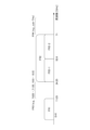
- a radio frame may be composed of one or more frames in the time domain. Each of the one or more frames in the time domain may be called a subframe. A subframe may further be composed of one or more slots in the time domain. A subframe may have a fixed time length (e.g., 1 ms) that is independent of numerology.
- Numerology may be a communication parameter that applies to at least one of the transmission and reception of a signal or channel. Numerology may indicate, for example, at least one of the following: subcarrier spacing (SCS), bandwidth, symbol length, cyclic prefix length, transmission time interval (TTI), number of symbols per TTI, radio frame structure, a specific filtering process performed by the transceiver in the frequency domain, a specific windowing process performed by the transceiver in the time domain, etc.
- SCS subcarrier spacing
- TTI transmission time interval
- radio frame structure a specific filtering process performed by the transceiver in the frequency domain
- a specific windowing process performed by the transceiver in the time domain etc.
- a slot may consist of one or more symbols in the time domain (such as OFDM (Orthogonal Frequency Division Multiplexing) symbols, SC-FDMA (Single Carrier Frequency Division Multiple Access) symbols, etc.).
- a slot may be a time unit based on numerology.
- a slot may include multiple minislots. Each minislot may consist of one or multiple symbols in the time domain. A minislot may also be called a subslot. A minislot may consist of fewer symbols than a slot.
- a PDSCH (or PUSCH) transmitted in a time unit larger than a minislot may be called PDSCH (or PUSCH) mapping type A.
- a PDSCH (or PUSCH) transmitted using a minislot may be called PDSCH (or PUSCH) mapping type B.
- Radio frame, subframe, slot, minislot, and symbol all represent time units for transmitting signals. Radio frame, subframe, slot, minislot, and symbol may each be referred to by a different name that corresponds to the radio frame, subframe, slot, minislot, and symbol.
- one subframe may be called a Transmission Time Interval (TTI)
- TTI Transmission Time Interval
- multiple consecutive subframes may be called a TTI
- one slot or one minislot may be called a TTI.
- at least one of the subframe and the TTI may be a subframe (1 ms) in existing LTE, a period shorter than 1 ms (e.g., 1-13 symbols), or a period longer than 1 ms.
- the unit representing the TTI may be called a slot, minislot, etc., instead of a subframe.
- TTI refers to, for example, the smallest time unit for scheduling in wireless communication.
- a base station performs scheduling to allocate wireless resources (such as frequency bandwidth and transmission power that can be used by each terminal 20) to each terminal 20 in TTI units.
- wireless resources such as frequency bandwidth and transmission power that can be used by each terminal 20
- TTI is not limited to this.
- the TTI may be a transmission time unit for a channel-coded data packet (transport block), a code block, a code word, etc., or may be a processing unit for scheduling, link adaptation, etc.
- the time interval e.g., the number of symbols
- the time interval in which a transport block, a code block, a code word, etc. is actually mapped may be shorter than the TTI.
- one or more TTIs may be the minimum time unit of scheduling.
- the number of slots (minislots) that constitute the minimum time unit of scheduling may be controlled.
- a TTI having a time length of 1 ms may be called a normal TTI (TTI in LTE Rel. 8-12), normal TTI, long TTI, normal subframe, normal subframe, long subframe, slot, etc.
- TTI shorter than a normal TTI may be called a shortened TTI, short TTI, partial or fractional TTI, shortened subframe, short subframe, minislot, subslot, slot, etc.
- a long TTI (e.g., a normal TTI, a subframe, etc.) may be interpreted as a TTI having a time length of more than 1 ms
- a short TTI e.g., a shortened TTI, etc.
- TTI length shorter than the TTI length of a long TTI and equal to or greater than 1 ms.
- a resource block is a resource allocation unit in the time domain and frequency domain, and may include one or more consecutive subcarriers in the frequency domain.
- the number of subcarriers included in an RB may be the same regardless of the numerology, and may be, for example, 12.
- the number of subcarriers included in an RB may be determined based on the numerology.
- the time domain of an RB may include one or more symbols and may be one slot, one minislot, one subframe, or one TTI in length.
- One TTI, one subframe, etc. may each be composed of one or more resource blocks.
- one or more RBs may be referred to as a physical resource block (PRB), a sub-carrier group (SCG), a resource element group (REG), a PRB pair, an RB pair, etc.
- PRB physical resource block
- SCG sub-carrier group
- REG resource element group
- PRB pair an RB pair, etc.
- a resource block may be composed of one or more resource elements (REs).
- REs resource elements
- one RE may be a radio resource area of one subcarrier and one symbol.
- a bandwidth part which may also be referred to as a partial bandwidth, may represent a subset of contiguous common resource blocks (RBs) for a given numerology on a given carrier, where the common RBs may be identified by an index of the RB relative to a common reference point of the carrier.
- PRBs may be defined in a BWP and numbered within the BWP.
- the BWP may include a BWP for UL (UL BWP) and a BWP for DL (DL BWP).
- UL BWP UL BWP
- DL BWP DL BWP
- One or more BWPs may be configured for a UE within one carrier.
- At least one of the configured BWPs may be active, and the UE may not expect to transmit or receive a given signal/channel outside the active BWP.
- BWP bitmap
- radio frames, subframes, slots, minislots, and symbols are merely examples.
- the number of subframes included in a radio frame, the number of slots per subframe or radio frame, the number of minislots included in a slot, the number of symbols and RBs included in a slot or minislot, the number of subcarriers included in an RB, as well as the number of symbols in a TTI, the symbol length, and the cyclic prefix (CP) length can be changed in various ways.
- a and B are different may mean “A and B are different from each other.”
- the term may also mean “A and B are each different from C.”
- Terms such as “separate” and “combined” may also be interpreted in the same way as “different.”
- notification of specific information is not limited to being done explicitly, but may be done implicitly (e.g., not notifying the specific information).
- Base station 110 Transmitter 120 Receiver 130 Setting unit 140 Control unit 20 Terminal 210 Transmitter 220 Receiver 230 Setting unit 240 Control unit 30 Power transmission equipment 40 Core network 1001 Processor 1002 Storage device 1003 Auxiliary storage device 1004 Communication device 1005 Input device 1006 Output device 2001 Vehicle 2002 Drive unit 2003 Steering unit 2004 Accelerator pedal 2005 Brake pedal 2006 Shift lever 2007 Front wheel 2008 Rear wheel 2009 Axle 2010 Electronic control unit 2012 Information service unit 2013 Communication module 2021 Current sensor 2022 Rotational speed sensor 2023 Air pressure sensor 2024 Vehicle speed sensor 2025 Acceleration sensor 2026 Brake pedal sensor 2027 Shift lever sensor 2028 Object detection sensor 2029 Accelerator pedal sensor 2030 Driving assistance system unit 2031 Microprocessor 2032 Memory (ROM, RAM) 2033 Communication port (IO port)
Landscapes
- Engineering & Computer Science (AREA)
- Computer Networks & Wireless Communication (AREA)
- Signal Processing (AREA)
- Mobile Radio Communication Systems (AREA)
Priority Applications (4)
| Application Number | Priority Date | Filing Date | Title |
|---|---|---|---|
| CN202380092750.3A CN120642501A (zh) | 2023-02-08 | 2023-02-08 | 终端及通信方法 |
| JP2024575946A JPWO2024166249A1 (enExample) | 2023-02-08 | 2023-02-08 | |
| EP23921081.8A EP4665027A1 (en) | 2023-02-08 | 2023-02-08 | Terminal and communication method |
| PCT/JP2023/004174 WO2024166249A1 (ja) | 2023-02-08 | 2023-02-08 | 端末及び通信方法 |
Applications Claiming Priority (1)
| Application Number | Priority Date | Filing Date | Title |
|---|---|---|---|
| PCT/JP2023/004174 WO2024166249A1 (ja) | 2023-02-08 | 2023-02-08 | 端末及び通信方法 |
Publications (1)
| Publication Number | Publication Date |
|---|---|
| WO2024166249A1 true WO2024166249A1 (ja) | 2024-08-15 |
Family
ID=92262129
Family Applications (1)
| Application Number | Title | Priority Date | Filing Date |
|---|---|---|---|
| PCT/JP2023/004174 Ceased WO2024166249A1 (ja) | 2023-02-08 | 2023-02-08 | 端末及び通信方法 |
Country Status (4)
| Country | Link |
|---|---|
| EP (1) | EP4665027A1 (enExample) |
| JP (1) | JPWO2024166249A1 (enExample) |
| CN (1) | CN120642501A (enExample) |
| WO (1) | WO2024166249A1 (enExample) |
Citations (1)
| Publication number | Priority date | Publication date | Assignee | Title |
|---|---|---|---|---|
| JP2020510362A (ja) * | 2017-03-24 | 2020-04-02 | クアルコム,インコーポレイテッド | ニューラジオにおけるデュアルモード動作のための技法 |
-
2023
- 2023-02-08 JP JP2024575946A patent/JPWO2024166249A1/ja active Pending
- 2023-02-08 CN CN202380092750.3A patent/CN120642501A/zh active Pending
- 2023-02-08 EP EP23921081.8A patent/EP4665027A1/en active Pending
- 2023-02-08 WO PCT/JP2023/004174 patent/WO2024166249A1/ja not_active Ceased
Patent Citations (1)
| Publication number | Priority date | Publication date | Assignee | Title |
|---|---|---|---|---|
| JP2020510362A (ja) * | 2017-03-24 | 2020-04-02 | クアルコム,インコーポレイテッド | ニューラジオにおけるデュアルモード動作のための技法 |
Non-Patent Citations (2)
| Title |
|---|
| 3GPP TS 38.300 V17.3.0 |
| SAMSUNG: "Discussion on UE mandatory CHBW", 3GPP DRAFT; R4-1713397-DICSUSSION ON BW (1), 3RD GENERATION PARTNERSHIP PROJECT (3GPP), MOBILE COMPETENCE CENTRE ; 650, ROUTE DES LUCIOLES ; F-06921 SOPHIA-ANTIPOLIS CEDEX ; FRANCE, vol. RAN WG4, no. Reno, USA; 20171127 - 20171201, 17 November 2017 (2017-11-17), Mobile Competence Centre ; 650, route des Lucioles ; F-06921 Sophia-Antipolis Cedex ; France , XP051374802 * |
Also Published As
| Publication number | Publication date |
|---|---|
| JPWO2024166249A1 (enExample) | 2024-08-15 |
| EP4665027A1 (en) | 2025-12-17 |
| CN120642501A (zh) | 2025-09-12 |
Similar Documents
| Publication | Publication Date | Title |
|---|---|---|
| WO2024166249A1 (ja) | 端末及び通信方法 | |
| WO2024166248A1 (ja) | 端末及び通信方法 | |
| WO2025069285A1 (ja) | 端末、基地局及び通信方法 | |
| WO2024157488A1 (ja) | 端末及び通信方法 | |
| WO2025074603A1 (ja) | 端末、基地局及び通信方法 | |
| WO2024100746A1 (ja) | 端末、基地局及び通信方法 | |
| WO2024201816A1 (ja) | 端末、基地局及び通信方法 | |
| WO2025069211A1 (ja) | 端末、基地局、及び通信方法 | |
| WO2024075289A1 (ja) | 端末、基地局及び通信方法 | |
| WO2024219387A1 (ja) | 端末及び通信方法 | |
| WO2024069904A1 (ja) | 端末及び通信方法 | |
| WO2024100892A1 (ja) | 端末、基地局及び通信方法 | |
| WO2025057340A1 (ja) | 端末及び通信方法 | |
| WO2024069903A1 (ja) | 端末及び通信方法 | |
| WO2025088814A1 (ja) | 端末、基地局、及び通信方法 | |
| WO2024100745A1 (ja) | 端末、基地局及び通信方法 | |
| WO2024084829A1 (ja) | 端末及び通信方法 | |
| WO2025083914A1 (ja) | 端末及び通信方法 | |
| WO2025154270A1 (ja) | 端末、基地局、及び通信方法 | |
| WO2025027813A1 (ja) | 端末及び通信方法 | |
| WO2024084839A1 (ja) | 端末及び通信方法 | |
| WO2024069989A1 (ja) | 端末及び通信方法 | |
| WO2024079796A1 (ja) | 端末及び通信方法 | |
| WO2025154269A1 (ja) | 端末、基地局、及び通信方法 | |
| WO2024100905A1 (ja) | 端末、基地局及び通信方法 |
Legal Events
| Date | Code | Title | Description |
|---|---|---|---|
| 121 | Ep: the epo has been informed by wipo that ep was designated in this application |
Ref document number: 23921081 Country of ref document: EP Kind code of ref document: A1 |
|
| ENP | Entry into the national phase |
Ref document number: 2024575946 Country of ref document: JP Kind code of ref document: A |
|
| WWE | Wipo information: entry into national phase |
Ref document number: 2024575946 Country of ref document: JP |
|
| WWE | Wipo information: entry into national phase |
Ref document number: 202380092750.3 Country of ref document: CN |
|
| NENP | Non-entry into the national phase |
Ref country code: DE |
|
| WWP | Wipo information: published in national office |
Ref document number: 202380092750.3 Country of ref document: CN |
|
| WWP | Wipo information: published in national office |
Ref document number: 2023921081 Country of ref document: EP |