WO2024166223A1 - 端末 - Google Patents
端末 Download PDFInfo
- Publication number
- WO2024166223A1 WO2024166223A1 PCT/JP2023/004060 JP2023004060W WO2024166223A1 WO 2024166223 A1 WO2024166223 A1 WO 2024166223A1 JP 2023004060 W JP2023004060 W JP 2023004060W WO 2024166223 A1 WO2024166223 A1 WO 2024166223A1
- Authority
- WO
- WIPO (PCT)
- Prior art keywords
- information
- relay station
- unit
- period
- gnb
- Prior art date
- Legal status (The legal status is an assumption and is not a legal conclusion. Google has not performed a legal analysis and makes no representation as to the accuracy of the status listed.)
- Ceased
Links
Images





Classifications
-
- H—ELECTRICITY
- H04—ELECTRIC COMMUNICATION TECHNIQUE
- H04W—WIRELESS COMMUNICATION NETWORKS
- H04W56/00—Synchronisation arrangements
-
- H—ELECTRICITY
- H04—ELECTRIC COMMUNICATION TECHNIQUE
- H04W—WIRELESS COMMUNICATION NETWORKS
- H04W84/00—Network topologies
- H04W84/02—Hierarchically pre-organised networks, e.g. paging networks, cellular networks, WLAN [Wireless Local Area Network] or WLL [Wireless Local Loop]
- H04W84/04—Large scale networks; Deep hierarchical networks
- H04W84/06—Airborne or Satellite Networks
Definitions
- This disclosure relates to a terminal that communicates with a base station via a relay station.
- the 3rd Generation Partnership Project (3GPP) is developing specifications for the 5th generation mobile communication system (5G, also known as New Radio (NR) or Next Generation (NG)) and is also developing specifications for the next generation of mobile communication systems, known as Beyond 5G, 5G Evolution or 6G.
- 5G also known as New Radio (NR) or Next Generation (NG)
- NG Next Generation
- NTNs are networks that include relay stations such as satellites, and terminals (User Equipment, UE) can communicate with base stations (next generation NodeB, gNB) via the relay stations.
- UE User Equipment
- the timing advance is set to compensate for the propagation delay between the UE and the gNB.
- the propagation distance changes as the relay station moves, so the TA needs to be updated periodically.
- the UE can maintain frequency/time synchronization with the gNB (Non-Patent Document 1).
- the amount of change in the propagation distance from the UE/gNB to the relay station varies depending on the position of the relay station (the elevation angle of the relay station as seen from the UE/gNB, hereinafter also referred to as the UE/gNB elevation angle).
- NTN specifies repeated transmission of channels in the uplink (UL) (Non-Patent Document 3).
- the channels in the UL are physical channels such as the Physical Uplink Shared Channel (PUSCH) and the Physical Uplink Control Channel (PUCCH).
- PUSCH Physical Uplink Shared Channel
- PUCCH Physical Uplink Control Channel
- DMRS bundling is a technology that performs channel estimation based on the DMRS of multiple channels in repeated transmission.
- TDW Time Domain Window
- the UE sets (reports) the above-mentioned maintenance period to the gNB for DMRS bundling applied to repeated channel transmission. Only one maintenance period can be reported. However, in a situation where the TA update frequency differs depending on the location of the relay station, limiting the number of maintenance periods that can be reported to one could cause the following problems.
- the maintenance period was set long assuming that the TA update frequency would be low, there was a risk that the TA would be updated during the maintenance period if the TA update frequency became high. This could result in power consistency and phase continuity not being maintained, and the accuracy of channel estimation decreasing.
- the maintenance period was set short assuming that the TA update frequency would be high, there was a problem that the processing load would be large and inefficient if the TA update frequency became low.
- the present disclosure has been made in light of these circumstances, and aims to provide a terminal that can report the maintenance period in response to changes in the update frequency of the TA.
- control unit 270 that assumes information related to a relay station that relays wireless communication with a base station
- a transmission unit radio signal transmission/reception unit 210) that reports a period during which updates to the terminal's transmission timing in the uplink that correspond to the information and that do not cause phase discontinuity are not performed.
- FIG. 1 is a diagram showing the overall configuration of a wireless communication system.
- FIG. 2 shows a diagram illustrating frequency ranges used in a wireless communication system.
- FIG. 3 is a diagram showing an example of the configuration of a radio frame, a subframe, a slot, and a symbol used in a radio communication system.
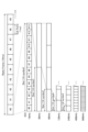
- FIG. 4 is a diagram illustrating an example of DMRS bundling.
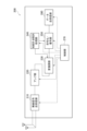
- FIG. 5 is a functional block diagram of the terminal.
- FIG. 6 is a functional block diagram of the base station.
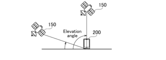
- FIG. 7 is a diagram showing an example of an elevation angle of a relay station as seen from a terminal.
- FIG. 1 is a diagram showing the overall configuration of a wireless communication system.
- FIG. 2 shows a diagram illustrating frequency ranges used in a wireless communication system.
- FIG. 3 is a diagram showing an example of the configuration of a radio frame, a subframe, a slot, and a symbol used in a radio communication system.
- FIG. 4 is a
- FIG. 8 is a diagram showing an example of an elevation angle of a relay station as viewed from a terminal and an elevation angle of a relay station as viewed from a base station.
- FIG. 9 is a diagram illustrating an example of a hardware configuration of a base station and a terminal.
- FIG. 10 is a diagram showing an example of the configuration of a vehicle.
- the wireless communication system 10 shown in Fig. 1 is a wireless communication system conforming to a method called 5G.
- the wireless communication system 10 may be a wireless communication system conforming to a method called Beyond 5G, 5G Evolution, or 6G.
- the wireless communication system 10 can support Massive Multiple-Input Multiple-Output (Massive MIMO), which generates more directional beams by controlling the wireless signals transmitted from multiple antenna elements, Carrier Aggregation (CA), which bundles together multiple component carriers (CC), and Dual Connectivity (DC), which communicates with two base stations simultaneously.
- Massive MIMO Massive Multiple-Input Multiple-Output
- CA Carrier Aggregation
- CC component carriers
- DC Dual Connectivity
- the wireless communication system 10 includes a Next Generation-Radio Access Network (NG-RAN) 20, a base station (next generation NodeB, gNB) 100 connected to the NG-RAN 20, and a terminal (User Equipment, UE) 200 that performs wireless communication with the gNB 100.
- the NG-RAN 20 is connected to a core network (CN) not shown.
- the NG-RAN 20 and the CN may be simply referred to as a "network.”
- the gNB 100 may also be understood to be included in the network. Note that the specific configuration of the wireless communication system 10, for example the number of gNBs 100 and UEs 200, is not limited to the example shown in FIG. 1.
- the wireless communication system 10 of the embodiment includes a relay station 150 that relays wireless communication between the gNB 100 and the UE 200.
- the relay station 150 is a satellite such as a GEO (Geostationary Earth Orbit) satellite, a MEO (Middle Earth Orbit) satellite, or a LEO (Low Earth Orbit) satellite.
- the relay station 150 may also be a High Altitude Platform Station (HAPS) mounted on an airship, balloon, or the like, or a commercial aircraft (Air to Ground, ATG).
- HAPS High Altitude Platform Station
- the relay station 150 of the embodiment is assumed to be an airborne vehicle as described above, but is not limited to this.
- the wireless communication system 10 may also support a plurality of frequency ranges (FRs). That is, as shown in FIG. 2, the wireless communication system 10 may support the following FRs: ⁇ FR1: 410MHz to 7.125GHz ⁇ FR2-1: 24.25GHz to 52.6GHz ⁇ FR2-2: Over 52.6GHz to 71GHz
- a subcarrier spacing (SCS) of 15, 30 or 60 kHz and a bandwidth (BW) of 5 to 100 MHz may be used.
- SCS subcarrier spacing
- BW bandwidth
- an SCS of 60 or 120 kHz (which may include 240 kHz) and a BW of 50 to 400 MHz may be used.
- Cyclic Prefix-Orthogonal Frequency Division Multiplexing CP-OFDM
- DFT-S-OFDM Discrete Fourier Transform-Spread-Orthogonal Frequency Division Multiplexing
- one slot in the wireless communication system 10 is composed of 14 symbols. If this configuration is maintained, the larger (wider) the SCS is, the shorter the symbol period (and slot period) will be.
- the SCS is not limited to the frequencies shown in FIG. 3, and may be, for example, frequencies such as 480 kHz and 960 kHz.
- the number of symbols constituting one slot does not necessarily have to be 14 symbols, and may be, for example, 28 or 56 symbols.
- the number of slots per subframe may differ depending on the SCS.
- the TA is a mechanism for controlling (advancing) the transmission timing of the UE 200 in the UL according to the distance from the gNB 100 (or from the reference point (RP) related to the synchronization between the downlink (DL) and the uplink (UL) in the NTN). Therefore, the TA can also be said to be a (controlled) transmission timing.
- the TA needs to be updated according to the change in the propagation path accompanying the movement of the relay station 150.
- the propagation distance considered in the calculation of the TA will be described, and the propagation distance not considered in the calculation of the TA (corresponding to User transparent in the figure) will not be described because it is assumed that it is solved in the gNB 100.
- the TA involving the UE 200 is calculated by the following formula, as specified in, for example, 3GPP TS 38.211 V17.3.0.
- T TA (N TA +N TA,UE-specific +N TA,common +N TA,offset ) ⁇ Tc
- T TA Timing advance between downlink and uplink
- N TA Timing advance between downlink and uplink
- N TA,UE-specific UE-derived timing correction
- common Network-controlled timing correction
- N TA,offset A fixed offset used to calculate the timing advance
- Tc Basic time unit for NR
- N TA is a closed loop TA.
- N TA is defined as 0 in the Physical Random Access Channel (PRACH).
- PRACH Physical Random Access Channel
- N TA is updated based on the TA Command field of msg2/msgB and the TA command of the medium access control layer control element (MAC CE).
- MAC CE medium access control layer control element
- N TA,UE-specific is an open-loop TA.
- N TA,UE-specific is a TA that UE 200 evaluates by itself to compensate for delay in a service link.
- N TA,UE-specific is calculated based on location information of UE 200 and orbit information of relay station 150. Note that the location information of UE 200 may be acquired based on a radio signal from a satellite positioning system (not shown), for example.
- N TA,common is an open-loop TA.
- N TA,common is a common TA controlled by the gNB100 (network).
- N TA,common is determined in the UE200 based on a parameter for determining a common TA notified by the gNB100.
- the reference point (RP) that specifies N TA,common may be set anywhere in the feeder link. That is, the RP may be set to the gNB 100, may be set to the relay station 150, or may be set between the gNB 100 and the relay station 150 as shown in Fig. 1.
- the RP is set to the gNB 100
- the burden on the gNB 100 is reduced.
- the RP is set to the relay station 150
- N TA,common becomes 0, and the burden on the UE 200 is reduced.
- open-loop TA may be referred to as TA pre-compensation.
- DMRS bundling is a technology that transmits DMRS while maintaining power consistency and phase continuity across multiple repeatedly transmitted channels, whereas previously DMRS was transmitted while maintaining power consistency and phase continuity across each repeatedly transmitted channel.
- DMRS bundling is a technology that performs channel estimation based on the DMRS of multiple channels that are repeatedly transmitted, whereas conventional channel estimation was performed based on the DMRS of each channel that is repeatedly transmitted.
- DMRS bundling may be called joint channel estimation.
- DMRS bundling can improve the accuracy of channel estimation.
- UE200 and gNB100 need to have a common understanding of the time period during which power consistency and phase continuity related to channel transmission are maintained for the above-mentioned DMRS bundling. Therefore, as shown in Figure 4, UE200 sets the actual TDW as the period during which power consistency and phase continuity are maintained, and repeatedly transmits the channel while maintaining power consistency and phase continuity during the actual TDW.
- the actual TDW is set as a period included in the pre-set nominal TDW. Therefore, the nominal TDW can be said to be the maximum period during which the above-mentioned power consistency and phase continuity are maintained. Therefore, UE200 may set the nominal TDW as the period during which power consistency and phase continuity are maintained.
- the actual/nominal TDW is set or determined to avoid events, whose occurrence makes it difficult to maintain power consistency and phase continuity.
- An example of an event is the above-mentioned TA update. Therefore, the actual/nominal TDW is not only a maintenance period during which power consistency and phase continuity are maintained, but can also be said to be a prohibition period during which events such as TA updates are prohibited.
- the period during which power consistency and phase continuity are maintained may be referred to as, but not limited to, the actual/nominal TDW, the maintenance period, the prohibited period, the actual/nominal TDW size, the bundling size, the interval, the time duration, the time duration for DMRS bundling, the time duration to avoid updating TA (TA pre-compensation) that may cause a phase discontinuity that may violate the UE's required performance, etc.
- These periods may also be interpreted as the maximum value of the period.
- UE 200 includes a wireless signal transmitting/receiving unit 210, an amplifier unit 220, a modulation/demodulation unit 230, a control signal/reference signal processing unit 240, an encoding/decoding unit 250, a data transmitting/receiving unit 260, and a control unit 270.
- the wireless signal transmitting/receiving unit 210 transmits and receives wireless signals to and from the gNB100.
- the wireless signal transmitting/receiving unit 210 may be configured as a transmitting unit that transmits wireless signals to the gNB100, and a receiving unit that receives wireless signals from the gNB100.
- the wireless signals include control signals and reference signals/data.
- the wireless signal transceiver 210 of the embodiment reports a maintenance period for maintaining power consistency and phase continuity. Specifically, it reports one or more maintenance periods corresponding to information (a single value or multiple values, described below) related to the relay station 150 assumed by the control unit 270.
- the wireless signal transceiver unit 210 can report one of the multiple period sets.
- the maintenance period may be interpreted as a period during which TA updates, i.e., updates to the transmission timing, are prohibited (prohibition period).
- the amplifier section 220 is composed of a power amplifier (PA)/low noise amplifier (LNA) etc.
- the amplifier section 220 amplifies the wireless signal output from the wireless signal transmitting/receiving section 210.
- the amplifier section 220 also amplifies the wireless signal output from the modulation/demodulation section 230.
- the modem unit 230 performs data modulation/demodulation, transmission power setting, resource block allocation, etc. for each predetermined communication destination (gNB100 or another gNB).
- CP-OFDM/DFT-S-OFDM may be applied in the modem unit 230.
- DFT-S-OFDM may be used not only for the uplink (UL) but also for the downlink (DL).
- the control signal/reference signal processing unit 240 performs processing related to control signals transmitted and received between the gNB 100, such as radio resource control (RRC) signaling.
- RRC radio resource control
- the control signal/reference signal processing unit 140 performs processing related to reference signals transmitted and received between the UE 200, such as Demodulation Reference Signal (DMRS), Phase Tracking Reference Signal (PTRS), Channel State Information-Reference Signal (CSI-RS), Sounding Reference Signal (SRS), and Positioning Reference Signal (PRS).
- DMRS Demodulation Reference Signal
- PTRS Phase Tracking Reference Signal
- CSI-RS Channel State Information-Reference Signal
- SRS Sounding Reference Signal
- PRS Positioning Reference Signal
- the channels include control channels and data channels.
- the control channels include the physical uplink control channel (PUCCH), physical downlink control channel (PDCCH), physical random access channel (PRACH), physical broadcast channel (PBCH), etc.
- the data channels include the physical uplink shared channel (PUSCH), physical downlink shared channel (PDSCH), etc.
- the encoding/decoding unit 250 performs operations such as splitting/concatenating and coding/decoding the data contained in the wireless signal for each specified communication destination (gNB100 or another gNB).
- the encoding/decoding unit 250 decodes the data output from the modem unit 230 and concatenates the decoded data.
- the encoding/decoding unit 250 also divides the data output from the data transmission/reception unit 260 into data of a predetermined size and performs coding on the divided data.
- the data transmission/reception unit 260 transmits and receives data to and from the gNB 100. Specifically, the data transmission/reception unit 260 performs assembly/disassembly of Protocol Data Units (PDUs)/Service Data Units (SDUs) between multiple layers.
- the multiple layers include the Medium Access Control (MAC) layer, the Radio Link Control (RLC) layer, and the Packet Data Convergence Protocol (PDCP) layer.
- the data transmission/reception unit 260 also performs data error correction and retransmission control based on Hybrid Automatic Repeat Request (HARQ).
- HARQ Hybrid Automatic Repeat Request
- the control unit 270 controls the UE 200.
- the control unit 270 controls, for example, the transmission and reception of radio signals by the radio signal transmitting and receiving unit 210, the amplification by the amplifier unit 220, the data modulation/demodulation by the modem unit 230, the signal processing by the control signal and reference signal processing unit 240, the coding/decoding by the encoding/decoding unit 250, and the transmission and reception of data by the data transmitting and receiving unit 260.
- the control unit 270 of the embodiment assumes one or more pieces of information related to the relay station 150.
- the control unit 270 may assume a single value or multiple values as the value of the one or more pieces of information related to the relay station 150.
- the information related to the relay station 150 may include a UE elevation angle, and may include a validity period of the information that is assumed to be set based on the position of the relay station 150.
- the UE elevation angle is the elevation angle of the relay station 150 as seen from the UE 200. In other words, it is the angle between a straight line connecting the UE 200 and the relay station 150 and the horizontal line.
- the validity period may be the validity period of the orbit information related to the relay station 150, or may be the validity period of a common timing advance (common TA) parameter related to the relay station 150, i.e., a parameter for determining the common TA notified by the gNB 100.
- common TA common timing advance
- the control unit 270 determines a maintenance period corresponding to the information related to the relay station 150, and causes the wireless signal transmitting/receiving unit 210 to report the maintenance period.
- the control unit 270 may also set multiple period sets each consisting of multiple maintenance periods, and cause the wireless signal transmitting/receiving unit 210 to report one period set.
- the control unit 270 may assume the gNB elevation angle as information related to the relay station 150, in addition to the UE elevation angle or the validity period of the information.
- the gNB elevation angle is the elevation angle of the relay station 150 as seen from the gNB 100. In other words, it is the angle between the straight line connecting the gNB 100 and the relay station 150 and the horizontal line.
- the gNB 100 includes a radio signal transceiver unit 110 and a control unit 120.
- the wireless signal transmitting/receiving unit 110 transmits and receives wireless signals to and from the UE 200.
- the wireless signal transmitting/receiving unit 110 may be configured as a transmitting unit that transmits wireless signals to the UE 200, and a receiving unit that receives wireless signals from the UE 200.
- the control unit 120 controls the gNB 100.
- the control unit 120 controls, for example, the transmission and reception of wireless signals by the wireless signal transmission and reception unit 210.
- the maintenance period was set long assuming that the TA update frequency would be low, there was a risk that the TA would be updated during the maintenance period if the TA update frequency became high. This could result in power consistency and phase continuity not being maintained, and the accuracy of channel estimation decreasing.
- the maintenance period was set short assuming that the TA update frequency would be high, there was a problem that the processing load would be large and inefficient if the TA update frequency became low.
- Example UE 200 reports the maximum value of the time duration for which TA (TA pre-compensation) update is not applied (executed) in a specific format, causing phase discontinuity that may violate the required performance of the UE.
- the maximum value of the time duration (T_max described later) is determined by UE 200 based on factors described later (UE elevation angle, validity period of information related to relay station 150, etc.). Note that the maximum value of the time duration may be read as the time duration. Also, "violating the required performance of the UE" may mean that phase continuity cannot be maintained, or may mean that a phase change exceeding a specific value occurs.
- UE 200 assumes a UE elevation angle as information related to relay station 150, for example, location information of relay station 150, and reports a maximum value T_max of the time duration corresponding to this UE elevation angle.
- the UE elevation angle may be interpreted as an elevation angle of relay station 150 as seen from UE 200.
- Option 1 Report one T_max corresponding to one UE elevation angle (eg, 30 degrees).
- Example 1 One UE elevation angle as mentioned above is defined in the specification.
- Example 2 The above-mentioned one UE elevation angle is set via an SIB such as an NTN-specific SIB.
- the NTN-specific SIB may be an SIB in which parameters for the NTN are transmitted, or may be SIB19. The same applies below. Effect: A simple mechanism can reduce the processing load.
- Option 2-1 (multiple values): Report T_max corresponding to multiple UE elevation angles (eg, 30 degrees, 60 degrees, 90 degrees).
- Option 2-2 (multiple values): Report T_max corresponding to multiple UE elevation angle ranges (e.g., 30 degrees or more and less than 60 degrees, 60 degrees or more and less than 90 degrees).
- Example 1 The above mentioned UE elevation angles or UE elevation angle ranges are defined in the specification.
- Example 2 The above-mentioned multiple UE elevation angles or multiple UE elevation angle ranges are set via a SIB, such as an NTN-specific SIB. Effect: UE 200 can set the maximum value of the required time duration (avoiding unnecessary scheduling).
- Option 3 Set multiple period sets consisting of T_max for each UE elevation angle, and report one of the multiple period sets. For example, report one index (e.g., Series#5) from the indexes of each period set (Series#0 to Series#9) in the list shown below. Note that A to J_max_10 to 90 deg in the list refers to T_max corresponding to the UE elevation angle of 10 to 90 degrees in the period set (Series#0 to Series#9).
- a to J_max_10 to 90 deg in the list refers to T_max corresponding to the UE elevation angle of 10 to 90 degrees in the period set (Series#0 to Series#9).
- Example 1 A set of periods consisting of T_max for each UE elevation angle as mentioned above is defined in the specification.
- Example 2 The above-mentioned set of time periods consisting of T_max for each UE elevation angle is configured via a SIB such as an NTN-specific SIB.
- SIB such as an NTN-specific SIB.
- UE 200 can set the maximum required time duration (avoiding unnecessary scheduling). Furthermore, overhead can be reduced because one index is reported instead of multiple T_max reports.
- the UE 200 assumes a validity period of the information related to the relay station 150, and reports a maximum value T_max of the time duration corresponding to the validity period.
- the validity period of the information related to the relay station 150 is assumed to be set based on the position of the relay station 150. That is, the closer the UE elevation angle is to 90 degrees, the lower the frequency of updating the TA, and therefore the longer the validity period is set. Also, the closer the UE elevation angle is to 0 degrees (180 degrees), the higher the frequency of updating the TA, and therefore the shorter the validity period is set.
- the validity period of the information related to the relay station 150 may be the validity period of the orbit information related to the relay station 150, or may be the validity period of the common TA parameters related to the relay station 150, i.e., the parameters for determining the common TA notified by the gNB 100.
- Option 1 Report one T_max corresponding to one validity period.
- the validity period mentioned above is defined in the specification.
- Example 2 The validity period is set via an SIB such as an NTN-specific SIB.
- the validity period referred to for reporting T_max may be a value indicated by a parameter indicating a conventional validity period (e.g., ntn-UlSyncValidityDuration), or may be a value indicated by a parameter defined separately from the parameter. Effect: A simple mechanism can reduce the processing load.
- Option 2 Report T_max corresponding to multiple validity periods (e.g., 10s, 20s, 30s).
- Example 1 The above multiple validity periods are defined in the specification.
- Example 2 The above multiple validity periods are set via a SIB, such as an NTN-specific SIB. Effect: UE 200 can set the maximum value of the required time duration (avoiding unnecessary scheduling).
- Option 3 Set multiple period sets consisting of T_max for each validity period, and report one of the multiple period sets. For example, report one index (for example, Series#5) from the indexes of each period set (Series#0 to Series#9) in the list shown below. Note that A to J_max_s5 to s240 in the list refer to the T_max corresponding to the validity period of 5s to 240s in the period set (Series#0 to Series#9).
- Example 1 A set of periods consisting of T_max for each validity period mentioned above is defined in the specification.
- Example 2 A set of periods consisting of T_max for each validity period described above is set via a SIB such as an NTN-specific SIB.
- Advantages: UE 200 can set the maximum required time duration (avoiding unnecessary scheduling). Furthermore, overhead can be reduced because one index is reported instead of multiple T_max reports.
- UE 200 may report T_max based on a specific gNB elevation angle or a specific common TA parameter set.
- the gNB elevation angle may be replaced with the elevation angle of relay station 150 seen from gNB 100, or may be replaced with the elevation angle (GW elevation angle) of relay station 150 seen from a gateway (GW).
- the method of reporting T_max is not limited to the above-described operation example 1 or operation example 2, and may be reported by another method. The same applies below.
- Option 1 Report T_max as described in Operational Example 1 or Operational Example 2 for one gNB elevation angle.
- Example 1 One gNB elevation angle as mentioned above is defined in the specification.
- Example 2 One gNB elevation angle as described above is set via a SIB, such as an NTN-specific SIB.
- Option 2 Report T_max as described in Operational Example 1 or Operational Example 2 for one set of common TA parameters.
- Example 1 A set of common TA parameters, as mentioned above, is defined in the specification.
- Example 2 One set of common TA parameters mentioned above is configured via a SIB such as an NTN-specific SIB.
- Option 3 Report T_max described in Operation Example 1 or Operation Example 2 for multiple gNB elevation angles (or gNB elevation angle ranges).
- Example 1 The above-mentioned multiple gNB elevation angles (or gNB elevation angle ranges) are defined in the specification.
- Example 2 The above-mentioned multiple gNB elevation angles (or gNB elevation angle ranges) are set via a SIB, such as an NTN-specific SIB.
- Option 4 Report T_max described in Operation Example 1 or Operation Example 2 for each set of multiple common TA parameters.
- Example 1 A set of common TA parameters as described above is defined in the specification.
- Example 2 The above-mentioned set of multiple common TA parameters is set via an SIB such as an NTN-specific SIB.
- the set of common TA parameters referenced for reporting T_max may be a set of conventional common TA parameters (e.g., parameters included in TAInfo) or a set of parameters defined separately from the set of parameters.
- Option 5 (Set of Values): The multiple period sets and their indices described in Operational Example 1 are defined in association with the gNB elevation angle.
- Example 1 The gNB elevation angles and associations mentioned above are defined in the specification.
- Example 2 The gNB elevation and associations described above are configured via a SIB, such as an NTN-specific SIB.
- Option 6 A plurality of period sets and their indices described in operation example 2 are defined in association with a set of common TA parameters.
- Example 1 The set and association of common TA parameters mentioned above is defined in a specification.
- Example 2 The set and association of common TA parameters mentioned above is configured via a SIB, such as an NTN-specific SIB.
- Effect of operation example 3 Reporting can be made taking into account feeder links.
- the UE 200 reports a maximum value T_max of a time duration corresponding to a parameter applied at a specific time point (e.g., information reporting time point).
- the above-mentioned parameters may include any of the UE elevation angle, the UE elevation angle range, the validity period of the information related to the relay station 150, the orbit information of the relay station 150, and a parameter for determining a common TA notified by the gNB 100.
- the UE 200 may perform the above-mentioned report at any time. For example, the UE 200 may perform the above-mentioned report at the timing when an update of the above-mentioned parameter is received or before the update is received. For example, the UE 200 may perform the above-mentioned report at the timing when the updated value of the above-mentioned parameter is applied or before the update is applied.
- Effect of operation example 4 When a change in the DMRS bundling size is required, the UE200 can report the information to the gNB100.
- the UE/gNB elevation angle may be interpreted as the UE/gNB depression angle as seen from the relay station.
- each piece of information or parameter (e.g., UE elevation angle) in the above disclosure may be information or parameters related to a serving cell, or may be information or parameters related to a neighbor cell.
- the information reported in the above disclosure may be information related to a serving cell, or may be information related to a neighbor cell.
- configure, activate, update, indicate, enable, specify, and select may be read as interchangeable.
- link, associate, correspond, and map may be read as interchangeable, and allocate, assign, monitor, and map may also be read as interchangeable.
- each functional block may be realized using one device that is physically or logically coupled, or may be realized using two or more devices that are physically or logically separated and connected directly or indirectly (e.g., using wires, wirelessly, etc.) and these multiple devices.
- the functional blocks may be realized by combining the one device or the multiple devices with software.
- Functions include, but are not limited to, judgement, determination, judgment, calculation, computation, processing, derivation, investigation, search, confirmation, reception, transmission, output, access, resolution, selection, election, establishment, comparison, assumption, expectation, regard, broadcasting, notifying, communicating, forwarding, configuring, reconfiguring, allocating, mapping, and assignment.
- a functional block (component) that performs the transmission function is called a transmitting unit or transmitter.
- FIG. 9 is a diagram showing an example of the hardware configuration of the device.
- the device may be configured as a computer device including a processor 1001, a memory 1002, a storage 1003, a communication device 1004, an input device 1005, an output device 1006, and a bus 1007.
- apparatus can be interpreted as a circuit, device, unit, etc.
- the hardware configuration of the apparatus may be configured to include one or more of the devices shown in the figure, or may be configured to exclude some of the devices.
- Each functional block of the device ( Figures 5 and 6) is realized by any hardware element of the computer device, or a combination of the hardware elements.
- each function of the device is realized by loading a specific software (program) onto hardware such as the processor 1001 and memory 1002, causing the processor 1001 to perform calculations, control communications by the communications device 1004, and control at least one of reading and writing data in the memory 1002 and storage 1003.
- a specific software program
- the processor 1001 for example, runs an operating system to control the entire computer.
- the processor 1001 may be configured as a central processing unit (CPU) that includes an interface with peripheral devices, a control unit, an arithmetic unit, registers, etc.
- CPU central processing unit
- the processor 1001 also reads out programs (program codes), software modules, data, etc. from at least one of the storage 1003 and the communication device 1004 into the memory 1002, and executes various processes according to these.
- the programs used are those that cause a computer to execute at least some of the operations described in the above-mentioned embodiments.
- the various processes described above may be executed by one processor 1001, or may be executed simultaneously or sequentially by two or more processors 1001.
- the processor 1001 may be implemented by one or more chips.
- the programs may be transmitted from a network via a telecommunications line.
- Memory 1002 is a computer-readable recording medium and may be composed of, for example, at least one of Read Only Memory (ROM), Erasable Programmable ROM (EPROM), Electrically Erasable Programmable ROM (EEPROM), Random Access Memory (RAM), etc.
- Memory 1002 may also be called a register, cache, main memory, etc.
- Memory 1002 can store a program (program code), software module, etc. capable of executing a method according to one embodiment of the present disclosure.
- Storage 1003 is a computer-readable recording medium, and may be, for example, at least one of an optical disk such as a Compact Disc ROM (CD-ROM), a hard disk drive, a flexible disk, a magneto-optical disk (e.g., a compact disk, a digital versatile disk, a Blu-ray (registered trademark) disk), a smart card, a flash memory (e.g., a card, a stick, a key drive), a floppy (registered trademark) disk, a magnetic strip, etc.
- Storage 1003 may also be referred to as an auxiliary storage device.
- the above-mentioned recording medium may be, for example, a database, a server, or other suitable medium including at least one of memory 1002 and storage 1003.
- the communication device 1004 is hardware (transmitting/receiving device) for communicating between computers via at least one of a wired network and a wireless network, and is also called, for example, a network device, a network controller, a network card, a communication module, etc.
- the communication device 1004 may be configured to include a high-frequency switch, a duplexer, a filter, a frequency synthesizer, etc., to realize, for example, at least one of Frequency Division Duplex (FDD) and Time Division Duplex (TDD).
- FDD Frequency Division Duplex
- TDD Time Division Duplex
- the input device 1005 is an input device (e.g., a keyboard, a mouse, a microphone, a switch, a button, a sensor, etc.) that accepts input from the outside.
- the output device 1006 is an output device (e.g., a display, a speaker, an LED lamp, etc.) that outputs to the outside. Note that the input device 1005 and the output device 1006 may be integrated into one device (e.g., a touch panel).
- each device such as the processor 1001 and the memory 1002 is connected by a bus 1007 for communicating information.
- the bus 1007 may be configured using a single bus, or may be configured using different buses between each device.
- the device may be configured to include hardware such as a microprocessor, a digital signal processor (DSP), an application specific integrated circuit (ASIC), a programmable logic device (PLD), or a field programmable gate array (FPGA), and some or all of the functional blocks may be realized by the hardware.
- DSP digital signal processor
- ASIC application specific integrated circuit
- PLD programmable logic device
- FPGA field programmable gate array
- the processor 1001 may be implemented using at least one of these pieces of hardware.
- the notification of information is not limited to the aspects/embodiments described in the present disclosure and may be performed using other methods.
- the notification of information may be performed by physical layer signaling (e.g., Downlink Control Information (DCI), Uplink Control Information (UCI)), higher layer signaling (e.g., RRC signaling, Medium Access Control (MAC) signaling), broadcast information (Master Information Block (MIB), System Information Block (SIB)), other signals, or a combination of these.
- RRC signaling may be referred to as an RRC message, and may be, for example, an RRC Connection Setup message, an RRC Connection Reconfiguration message, etc.
- LTE Long Term Evolution
- LTE-A LTE-Advanced
- SUPER 3G IMT-Advanced
- 4G 5th generation mobile communication system
- 5G Future Radio Access
- FAA New Radio
- NR New Radio
- W-CDMA registered trademark
- GSM registered trademark
- UMB Ultra Mobile Broadband
- IEEE 802.11 Wi-Fi (registered trademark)
- IEEE 802.16 WiMAX (registered trademark)
- IEEE 802.20 Ultra-WideBand (UWB), Bluetooth (registered trademark), or other suitable systems and next generation systems enhanced therefrom.
- Multiple systems may also be applied in combination (e.g., a combination of at least one of LTE and LTE-A with 5G).
- certain operations that are described as being performed by a base station may in some cases be performed by its upper node.
- various operations performed for communication with a terminal may be performed by at least one of the base station and other network nodes other than the base station (such as, but not limited to, an MME or an S-GW).
- the above example shows a case where there is one other network node other than the base station, it may also be a combination of multiple other network nodes (such as an MME and an S-GW).
- Information, signals can be output from a higher layer (or a lower layer) to a lower layer (or a higher layer). They may be input and output via multiple network nodes.
- the input and output information may be stored in a specific location (e.g., memory) or may be managed using a management table.
- the input and output information may be overwritten, updated, or appended.
- the output information may be deleted.
- the input information may be sent to another device.
- the determination may be based on a value represented by one bit (0 or 1), a Boolean value (true or false), or a numerical comparison (e.g., a comparison with a predetermined value).
- notification of specific information is not limited to being done explicitly, but may be done implicitly (e.g., not notifying the specific information).
- Software shall be construed broadly to mean instructions, instruction sets, code, code segments, program code, programs, subprograms, software modules, applications, software applications, software packages, routines, subroutines, objects, executable files, threads of execution, procedures, functions, etc., whether referred to as software, firmware, middleware, microcode, hardware description language, or otherwise.
- software, instructions, information, etc. may be transmitted and received over a transmission medium.
- a transmission medium For example, if software is transmitted from a website, server, or other remote source using at least one of wired technologies (such as coaxial cable, fiber optic cable, twisted pair, Digital Subscriber Line (DSL)), and/or wireless technologies (such as infrared, microwave, etc.), then at least one of these wired and wireless technologies is included within the definition of a transmission medium.
- wired technologies such as coaxial cable, fiber optic cable, twisted pair, Digital Subscriber Line (DSL)
- wireless technologies such as infrared, microwave, etc.
- the information, signals, etc. described in this disclosure may be represented using any of a variety of different technologies.
- the data, instructions, commands, information, signals, bits, symbols, chips, etc. that may be referred to throughout the above description may be represented by voltages, currents, electromagnetic waves, magnetic fields or magnetic particles, optical fields or photons, or any combination thereof.
- the channel and the symbol may be a signal (signaling).
- the signal may be a message.
- the component carrier (CC) may be called a carrier frequency, a cell, a frequency carrier, etc.
- system and “network” are used interchangeably.
- a radio resource may be indicated by an index.
- the names used for the above-mentioned parameters are not limiting in any respect. Furthermore, the formulas etc. using these parameters may differ from those explicitly disclosed in this disclosure.
- the various channels (e.g., PUCCH, PDCCH, etc.) and information elements may be identified by any suitable names, and therefore the various names assigned to these various channels and information elements are not limiting in any respect.
- Base station BS
- wireless base station fixed station
- NodeB NodeB
- eNodeB eNodeB
- gNodeB gNodeB
- a base station can accommodate one or more (e.g., three) cells (also called sectors). If a base station accommodates multiple cells, the overall coverage area of the base station can be divided into multiple smaller areas, and each smaller area can also provide communication services by a base station subsystem (e.g., a small indoor base station (Remote Radio Head: RRH)).
- a base station subsystem e.g., a small indoor base station (Remote Radio Head: RRH)
- cell refers to part or all of the coverage area of a base station and/or a base station subsystem that provides communication services within that coverage.
- MS Mobile Station
- UE User Equipment
- a mobile station may also be referred to by those skilled in the art as a subscriber station, mobile unit, subscriber unit, wireless unit, remote unit, mobile device, wireless device, wireless communication device, remote device, mobile subscriber station, access terminal, mobile terminal, wireless terminal, remote terminal, handset, user agent, mobile client, client, or some other suitable terminology.
- At least one of the base station and the mobile station may be called a transmitting device, a receiving device, a communication device, etc.
- At least one of the base station and the mobile station may be a device mounted on a moving object, or the moving object itself, etc.
- the moving object may be a vehicle (e.g., a car, an airplane, etc.), an unmanned moving object (e.g., a drone, an autonomous vehicle, etc.), or a robot (manned or unmanned).
- At least one of the base station and the mobile station may include a device that does not necessarily move during communication operations.
- at least one of the base station and the mobile station may be an Internet of Things (IoT) device such as a sensor.
- IoT Internet of Things
- the base station in the present disclosure may be interpreted as a mobile station (user terminal, the same applies below).
- each aspect/embodiment of the present disclosure may be applied to a configuration in which communication between a base station and a mobile station is replaced with communication between multiple mobile stations (which may be called, for example, Device-to-Device (D2D), Vehicle-to-Everything (V2X), etc.).
- the mobile station may be configured to have the functions of a base station.
- terms such as "uplink” and "downlink” may be interpreted as terms corresponding to communication between terminals (for example, "side”).
- the uplink channel, downlink channel, etc. may be interpreted as a side channel.
- the mobile station in this disclosure may be interpreted as a base station.
- the base station may be configured to have the functions of the mobile station.
- a radio frame may be composed of one or more frames in the time domain. Each of the one or more frames in the time domain may be called a subframe.
- a subframe may further be composed of one or more slots in the time domain.
- a subframe may have a fixed time length (e.g., 1 ms) that is independent of numerology.
- Numerology may be a communication parameter that applies to at least one of the transmission and reception of a signal or channel. Numerology may indicate, for example, at least one of the following: Subcarrier Spacing (SCS), bandwidth, symbol length, cyclic prefix length, Transmission Time Interval (TTI), number of symbols per TTI, radio frame structure, a particular filtering operation performed by the transceiver in the frequency domain, a particular windowing operation performed by the transceiver in the time domain, etc.
- SCS Subcarrier Spacing
- TTI Transmission Time Interval
- radio frame structure a particular filtering operation performed by the transceiver in the frequency domain, a particular windowing operation performed by the transceiver in the time domain, etc.
- a slot may consist of one or more symbols in the time domain (e.g., Orthogonal Frequency Division Multiplexing (OFDM) symbols, Single Carrier Frequency Division Multiple Access (SC-FDMA) symbols, etc.).
- OFDM Orthogonal Frequency Division Multiplexing
- SC-FDMA Single Carrier Frequency Division Multiple Access
- a slot may be a numerology-based unit of time.
- a slot may include multiple minislots. Each minislot may consist of one or multiple symbols in the time domain. A minislot may also be called a subslot. A minislot may consist of fewer symbols than a slot.
- a PDSCH (or PUSCH) transmitted in a time unit larger than a minislot may be called PDSCH (or PUSCH) mapping type A.
- a PDSCH (or PUSCH) transmitted using a minislot may be called PDSCH (or PUSCH) mapping type B.
- Radio frame, subframe, slot, minislot, and symbol all represent time units for transmitting signals. Radio frame, subframe, slot, minislot, and symbol may each be referred to by a different name that corresponds to the radio frame, subframe, slot, minislot, and symbol.
- one subframe may be called a transmission time interval (TTI)
- TTI transmission time interval
- multiple consecutive subframes may be called a TTI
- one slot or one minislot may be called a TTI.
- at least one of the subframe and the TTI may be a subframe (1 ms) in existing LTE, a period shorter than 1 ms (e.g., 1-13 symbols), or a period longer than 1 ms.
- the unit expressing the TTI may be called a slot, minislot, etc., instead of a subframe.
- TTI refers to, for example, the smallest time unit for scheduling in wireless communication.
- a base station schedules each user terminal by allocating radio resources (such as frequency bandwidth and transmission power that can be used by each user terminal) in TTI units.
- radio resources such as frequency bandwidth and transmission power that can be used by each user terminal
- the TTI may be a transmission time unit for a channel-coded data packet (transport block), a code block, a code word, etc., or may be a processing unit for scheduling, link adaptation, etc.
- the time interval e.g., the number of symbols
- the time interval in which a transport block, a code block, a code word, etc. is actually mapped may be shorter than the TTI.
- one slot or one minislot when called a TTI, one or more TTIs (i.e., one or more slots or one or more minislots) may be the minimum time unit of scheduling.
- the number of slots (minislots) that constitute the minimum time unit of scheduling may be controlled.
- a TTI having a time length of 1 ms may be referred to as a normal TTI (TTI in LTE Rel. 8-12), normal TTI, long TTI, normal subframe, normal subframe, long subframe, slot, etc.
- TTI shorter than a normal TTI may be referred to as a shortened TTI, short TTI, partial or fractional TTI, shortened subframe, short subframe, minislot, subslot, slot, etc.
- a long TTI (e.g., a normal TTI, a subframe, etc.) may be interpreted as a TTI having a time length of more than 1 ms
- a short TTI e.g., a shortened TTI, etc.
- a resource block is a resource allocation unit in the time domain and frequency domain, and may include one or more consecutive subcarriers in the frequency domain.
- the number of subcarriers included in an RB may be the same regardless of the numerology, and may be, for example, 12.
- the number of subcarriers included in an RB may be determined based on the numerology.
- the time domain of an RB may include one or more symbols and may be one slot, one minislot, one subframe, or one TTI in length.
- One TTI, one subframe, etc. may each be composed of one or more resource blocks.
- one or more RBs may also be referred to as a physical resource block (PRB), a sub-carrier group (SCG), a resource element group (REG), a PRB pair, an RB pair, etc.
- PRB physical resource block
- SCG sub-carrier group
- REG resource element group
- PRB pair an RB pair, etc.
- a resource block may be composed of one or more resource elements (RE).
- RE resource elements
- one RE may be a radio resource area of one subcarrier and one symbol.
- a Bandwidth Part which may also be referred to as a partial bandwidth, may represent a subset of contiguous common resource blocks (RBs) for a given numerology on a given carrier, where the common RBs may be identified by an index of the RB relative to a common reference point of the carrier.
- PRBs may be defined in a BWP and numbered within that BWP.
- the BWP may include a BWP for UL (UL BWP) and a BWP for DL (DL BWP).
- UL BWP UL BWP
- DL BWP DL BWP
- One or more BWPs may be configured for a UE within one carrier.
- At least one of the configured BWPs may be active, and the UE may not expect to transmit or receive a given signal/channel outside the active BWP.
- BWP bitmap
- radio frames, subframes, slots, minislots, and symbols are merely examples.
- the number of subframes included in a radio frame, the number of slots per subframe or radio frame, the number of minislots included in a slot, the number of symbols and RBs included in a slot or minislot, the number of subcarriers included in an RB, as well as the number of symbols in a TTI, the symbol length, the cyclic prefix (CP) length, and other configurations can be changed in various ways.
- connection refers to any direct or indirect connection or coupling between two or more elements, and may include the presence of one or more intermediate elements between two elements that are “connected” or “coupled” to each other.
- the coupling or connection between elements may be physical, logical, or a combination thereof.
- “connected” may be read as "access.”
- two elements may be considered to be “connected” or “coupled” to each other using at least one of one or more wires, cables, and printed electrical connections, as well as electromagnetic energy having wavelengths in the radio frequency range, microwave range, and optical (both visible and invisible) range, as some non-limiting and non-exhaustive examples.
- the reference signal may also be abbreviated as Reference Signal (RS) or referred to as a pilot depending on the applicable standard.
- RS Reference Signal
- the phrase “based on” does not mean “based only on,” unless expressly stated otherwise. In other words, the phrase “based on” means both “based only on” and “based at least on.”
- any reference to an element using a designation such as "first,” “second,” etc., used in this disclosure does not generally limit the quantity or order of those elements. These designations may be used in this disclosure as a convenient method of distinguishing between two or more elements. Thus, a reference to a first and a second element does not imply that only two elements may be employed therein or that the first element must precede the second element in some way.
- determining may encompass a wide variety of actions.
- Determining and “determining” may include, for example, judging, calculating, computing, processing, deriving, investigating, looking up, search, inquiry (e.g., searching in a table, database, or other data structure), ascertaining something that is deemed to be a “judging” or “determining,” and the like.
- Determining and “determining” may also include receiving (e.g., receiving information), transmitting (e.g., sending information), input, output, accessing (e.g., accessing data in memory), and the like.
- judgment and “decision” can include considering resolving, selecting, choosing, establishing, comparing, etc., to have been “judged” or “decided.” In other words, “judgment” and “decision” can include considering some action to have been “judged” or “decided.” Additionally, “judgment” can be interpreted as “assuming,” “expecting,” “considering,” etc.
- a and B are different may mean “A and B are different from each other.”
- the term may also mean “A and B are each different from C.”
- Terms such as “separate” and “combined” may also be interpreted in the same way as “different.”
- FIG. 10 shows an example of the configuration of a vehicle 2001.
- the vehicle 2001 includes a drive unit 2002, a steering unit 2003, an accelerator pedal 2004, a brake pedal 2005, a shift lever 2006, left and right front wheels 2007, left and right rear wheels 2008, an axle 2009, an electronic control unit 2010, various sensors 2021-2029, an information service unit 2012, and a communication module 2013.
- the drive unit 2002 is composed of, for example, an engine, a motor, or a hybrid of an engine and a motor.
- the steering unit 2003 includes at least a steering wheel (also called a handle) and is configured to steer at least one of the front wheels and the rear wheels based on the operation of the steering wheel operated by the user.
- a steering wheel also called a handle
- the electronic control unit 2010 is composed of a microprocessor 2031, a memory (ROM, RAM) 2032, and a communication port (IO port) 2033. Signals are input to the electronic control unit 2010 from various sensors 2021 to 2027 provided in the vehicle.
- the electronic control unit 2010 may also be called an ECU (Electronic Control Unit).
- Signals from the various sensors 2021 to 2028 include a current signal from a current sensor 2021 that senses the current of the motor, a rotation speed signal of the front and rear wheels acquired by a rotation speed sensor 2022, an air pressure signal of the front and rear wheels acquired by an air pressure sensor 2023, a vehicle speed signal acquired by a vehicle speed sensor 2024, an acceleration signal acquired by an acceleration sensor 2025, an accelerator pedal depression amount signal acquired by an accelerator pedal sensor 2029, a brake pedal depression amount signal acquired by a brake pedal sensor 2026, a shift lever operation signal acquired by a shift lever sensor 2027, and a detection signal for detecting obstacles, vehicles, pedestrians, etc. acquired by an object detection sensor 2028.
- the information service unit 2012 is composed of various devices, such as a car navigation system, an audio system, speakers, a television, and a radio, for providing various types of information such as driving information, traffic information, and entertainment information, and one or more ECUs for controlling these devices.
- the information service unit 2012 uses information acquired from external devices via the communication module 2013, etc., to provide various types of multimedia information and multimedia services to the occupants of the vehicle 1.
- the driving assistance system unit 2030 is composed of various devices that provide functions for preventing accidents and reducing the driving burden on the driver, such as a millimeter wave radar, LiDAR (Light Detection and Ranging), a camera, a positioning locator (e.g., GNSS, etc.), map information (e.g., high definition (HD) map, autonomous vehicle (AV) map, etc.), a gyro system (e.g., IMU (Inertial Measurement Unit), INS (Inertial Navigation System), etc.), AI (Artificial Intelligence) chip, and an AI processor, as well as one or more ECUs that control these devices.
- the driving assistance system unit 2030 also transmits and receives various information via the communication module 2013 to realize driving assistance functions or autonomous driving functions.
- the communication module 2013 can communicate with the microprocessor 2031 and components of the vehicle 1 via the communication port.
- the communication module 2013 transmits and receives data via the communication port 2033 between the drive unit 2002, steering unit 2003, accelerator pedal 2004, brake pedal 2005, shift lever 2006, left and right front wheels 2007, left and right rear wheels 2008, axle 2009, microprocessor 2031 and memory (ROM, RAM) 2032 in electronic control unit 2010, and sensors 2021 to 2028, which are provided on the vehicle 2001.
- the communication module 2013 is a communication device that can be controlled by the microprocessor 2031 of the electronic control unit 2010 and can communicate with an external device. For example, it transmits and receives various information to and from the external device via wireless communication.
- the communication module 2013 may be located either inside or outside the electronic control unit 2010.
- the external device may be, for example, a base station, a mobile station, etc.
- the communication module 2013 transmits a current signal from the current sensor input to the electronic control unit 2010 to an external device via wireless communication.
- the communication module 2013 also transmits to an external device via wireless communication the following signals input to the electronic control unit 2010: a front wheel or rear wheel rotation speed signal acquired by a rotation speed sensor 2022, a front wheel or rear wheel air pressure signal acquired by an air pressure sensor 2023, a vehicle speed signal acquired by a vehicle speed sensor 2024, an acceleration signal acquired by an acceleration sensor 2025, an accelerator pedal depression amount signal acquired by an accelerator pedal sensor 2029, a brake pedal depression amount signal acquired by a brake pedal sensor 2026, a shift lever operation signal acquired by a shift lever sensor 2027, and a detection signal for detecting an obstacle, a vehicle, a pedestrian, etc. acquired by an object detection sensor 2028.
- the communication module 2013 receives various information (traffic information, signal information, vehicle distance information, etc.) transmitted from an external device, and displays it on an information service unit 2012 provided in the vehicle.
- the communication module 2013 also stores the various information received from the external device in a memory 2032 that can be used by the microprocessor 2031.
- the microprocessor 2031 may control the drive unit 2002, steering unit 2003, accelerator pedal 2004, brake pedal 2005, shift lever 2006, left and right front wheels 2007, left and right rear wheels 2008, axles 2009, sensors 2021-2028, and the like provided in the vehicle 2001.
- the first feature is a terminal equipped with a control unit that assumes information related to a relay station that relays wireless communication with a base station, and a transmission unit that reports a period during which updates to the terminal's transmission timing in the uplink that correspond to the information are not performed and which causes phase discontinuity.
- the second feature is the terminal according to the first feature, in which the information includes an elevation angle of the relay station as seen from the terminal.
- the third feature is that in the first feature, the information includes orbit information related to the relay station or a validity period of a common timing advance parameter.
- the fourth feature is that in any one of the first to third features, the information includes an elevation angle of the relay station as seen from the base station.
- the fifth feature is a terminal according to any one of the first to fourth features, in which the control unit assumes a single value as the value of the information, and the transmission unit reports the period that corresponds to the single value.
- the sixth feature is a terminal according to any one of the first to fourth features, in which the control unit assumes a plurality of values as the value of the information, and the transmission unit reports a plurality of the periods corresponding to each of the plurality of values.
- Wireless Communication Systems 20 NG-RAN 100 gNB 110 Radio signal transmitting/receiving unit 120 Control unit 150 Relay station 200 UE 210 Radio signal transmitting/receiving unit 220 Amplifier unit 230 Modulation/demodulation unit 240 Control signal/reference signal processing unit 250 Encoding/decoding unit 260 Data transmitting/receiving unit 270 Control unit 1001 Processor 1002 Memory 1003 Storage 1004 Communication device 1005 Input device 1006 Output device 1007 Bus 2001 Vehicle 2002 Drive unit 2003 Steering unit 2004 Accelerator pedal 2005 Brake pedal 2006 Shift lever 2007 Left and right front wheels 2008 Left and right rear wheels 2009 Axle 2010 Electronic control unit 2012 Information service unit 2013 Communication module 2021 Current sensor 2022 RPM sensor 2023 Air pressure sensor 2024 Vehicle speed sensor 2025 Acceleration sensor 2026 Brake pedal sensor 2027 Shift lever sensor 2028 Object detection sensor 2029 Accelerator pedal sensor 2030 Driving assistance system section 2031 Microprocessor 2032 Memory (ROM, RAM) 2033 communication port
Landscapes
- Engineering & Computer Science (AREA)
- Computer Networks & Wireless Communication (AREA)
- Signal Processing (AREA)
- Physics & Mathematics (AREA)
- Astronomy & Astrophysics (AREA)
- General Physics & Mathematics (AREA)
- Mobile Radio Communication Systems (AREA)
Abstract
端末は、基地局との無線通信を中継する中継局に係る情報を想定する制御部と、前記情報に対応する、上りリンクにおける端末の送信タイミングの更新であって、位相の非連続性を引き起こす更新を実行しない期間を報告する送信部と、を備える。
Description
本開示は、中継局を介して基地局と通信する端末に関する。
3rd Generation Partnership Project(3GPP)は、5th generation mobile communication system(5G、New Radio(NR)またはNext Generation(NG)とも呼ばれる。)を仕様化し、さらに、Beyond 5G、5G Evolutionあるいは6Gと呼ばれる次世代の移動通信システムの仕様化も進めている。
3GPPにおいて、非地上型ネットワーク(Non-Terrestrial Network、NTN)のカバレッジ向上が議論されている。NTNは、衛星などの中継局を含むネットワークであり、端末(User Equipment、UE)は、中継局を介して基地局(next Generation NodeB、gNB)と通信することができる。
gNBとの間に生じる伝搬遅延を補償するために、タイミングアドバンス(TA)が設定される。NTNにおいては、中継局の移動に伴い伝搬距離が変化するので、定期的にTAを更新する必要がある。TAを更新することにより、UEは、gNBとの周波数/時間の同期を維持することができる(非特許文献1)。
また、UE/gNBから中継局までの伝搬距離の変化量は、中継局の位置(UE/gNBから見た中継局の仰角、以下、UE/gNB仰角ともいう。)によって異なることが知られている。具体的には、UE/gNB仰角が90度に近いほど伝搬距離の変化量が小さく、UE/gNB仰角が0度(180度)に近いほど伝搬距離の変化量が大きい(非特許文献2)。従って、TAの更新頻度は、UE/gNB仰角が90度に近いほど低く、UE/gNB仰角が0度(180度)に近いほど高いことが望ましい。
さらに、NTNにおいて、上りリンク(Uplink、UL)におけるチャネルの繰り返し送信が規定されている(非特許文献3)。ULにおけるチャネルは、例えば、物理上りリンク共有チャネル(Physical Uplink Shared Channel、PUSCH)、物理上りリンク制御チャネル(Physical Uplink Control Channel、PUCCH)などの物理チャネルである。
3GPP TS 38.213 V17.3.0, 3rd Generation Partnership Project; Technical Specification Group Radio Access Network; NR; Physical layer procedures for control (Release 17), 3GPP, 2022年9月
"Discussion on coverage enhancement for NR-NTN", 3GPP TSG RAN WG1 #111, 3GPP, November 14th - 18th, 2022
3GPP TS 38.214 V17.3.0, 3rd Generation Partnership Project; Technical Specification Group Radio Access Network; NR; Physical layer procedures for control (Release 17), 3GPP, 2022年9月
チャネルの繰り返し送信においては、gNBが正確にチャネル推定を行うために、復調用参照信号(DMRS)バンドリングが適用される。DMRSバンドリングは、繰り返し送信における複数のチャネルのDMRSに基づいてチャネル推定を行う技術である。DMRSバンドリングに用いられる複数のDMRSの送信においては、power consistency及びphase continuityを維持する必要がある。ここで、power consistency及びphase continuityを維持する期間は、actual Time Domain Window(TDW)などの維持期間として設定(決定)される。
UEは、gNBに対して、チャネルの繰り返し送信に適用されるDMRSバンドリングのために、上述した維持期間を設定(報告)する。報告可能な維持期間は1つに限られる。しかしながら、TAの更新頻度が中継局の位置によって異なるという状況において、報告可能な維持期間が1つに限られることは、以下のような問題を引き起こすおそれがあった。
TAの更新頻度が低い場合を想定して維持期間を長く設定すると、TAの更新頻度が高くなった場合に、維持期間においてTAの更新が発生するおそれがあった。これにより、power consistency及びphase continuityが維持されなくなり、チャネル推定の精度が低下するおそれがあった。一方で、TAの更新頻度が高い場合を想定して維持期間を短く設定すると、TAの更新頻度が低くなった場合に、処理負荷が大きく、効率的でないという問題があった。
そこで、本開示は、このような状況に鑑みてなされたものであり、TAの更新頻度の変化に応じて維持期間を報告することができる端末の提供を目的とする。
基地局との無線通信を中継する中継局に係る情報を想定する制御部(制御部270)と、前記情報に対応する、上りリンクにおける端末の送信タイミングの更新であって、位相の非連続性を引き起こす更新を実行しない期間を報告する送信部(無線信号送受信部210)と、を備える端末である。
以下、実施形態を図面に基づいて説明する。なお、同一の機能や構成には、同一または類似の符号を付して、その説明を適宜省略する。
(1)無線通信システムの構成
(1.1)概略構成
図1に示す無線通信システム10は、5Gと呼ばれる方式に従った無線通信システムである。一方で、無線通信システム10は、Beyond 5G、5G Evolutionあるいは6Gと呼ばれる方式に従った無線通信システムであってもよい。
(1.1)概略構成
図1に示す無線通信システム10は、5Gと呼ばれる方式に従った無線通信システムである。一方で、無線通信システム10は、Beyond 5G、5G Evolutionあるいは6Gと呼ばれる方式に従った無線通信システムであってもよい。
無線通信システム10は、複数のアンテナ素子から送信される無線信号を制御することによって、より指向性の高いビームを生成するMassive Multiple-Input Multiple-Output(Massive MIMO)、複数のコンポーネントキャリア(CC)を束ねて用いるキャリアアグリゲーション(CA)、2つの基地局と同時通信を行うデュアルコネクティビティ(DC)などをサポートすることができる。
図1に示すように、無線通信システム10は、Next Generation-Radio Access Network(NG-RAN)20と、NG-RAN20に接続される基地局(next Generation NodeB、gNB)100と、gNB100と無線通信を行う端末(User Equipment、UE)200とを含む。NG-RAN20は、図示しないコアネットワーク(CN)に接続される。NG-RAN20及びCNは、単に「ネットワーク」と表現されてもよい。また、gNB100は、ネットワークに含まれると解されてもよい。なお、無線通信システム10の具体的な構成、例えばgNB100及びUE200の数は、図1に示す例に限定されない。
実施形態の無線通信システム10は、gNB100とUE200との無線通信を中継する中継局150を含む。中継局150は、GEO(Geostationary Earth Orbit)衛星、MEO(Middle Earth Orbit)衛星、LEO(Low Earth Orbit)衛星などの衛星である。また、中継局150は、飛行船、気球などに搭載される高高度基盤ステーション(High Altitude Platform Station、HAPS)であってもよいし、商用航空機(Air to Ground、ATG)であってもよい。実施形態の中継局150は、上述したように飛翔体を想定しているが、これに限られない。
また、無線通信システム10は、複数の周波数レンジ(FR)に対応してもよい。すなわち、図2に示すように、次のようなFRに対応してもよい。
・FR1:410MHz~7.125GHz
・FR2-1:24.25GHz~52.6GHz
・FR2-2: 52.6GHz超~71GHz
・FR1:410MHz~7.125GHz
・FR2-1:24.25GHz~52.6GHz
・FR2-2: 52.6GHz超~71GHz
FR1においては、15、30または60kHzのサブキャリア間隔(SCS)及び5~100MHzの帯域幅(BW)が用いられてもよい。FR2-1においては、60または120kHz(240kHzが含まれてもよい。)のSCS及び50~400MHzのBWが用いられてもよい。
FR2-2においては、位相雑音の増大を避けるために、より大きなSCSを有するCyclic Prefix-Orthogonal Frequency Division Multiplexing(CP-OFDM)またはDiscrete Fourier Transform-Spread-Orthogonal Frequency Division Multiplexing(DFT-S-OFDM)を適用してもよい。
また、図3に示すように、無線通信システム10における1スロットは、14シンボルで構成される。この構成が維持される場合、SCSが大きく(広く)なるほど、シンボル期間(及びスロット期間)は短くなる。なお、SCSは、図3に示す周波数に限定されず、例えば、480kHz、960kHzなどの周波数であってもよい。
また、1スロットを構成するシンボル数は、必ずしも14シンボルでなくてもよく、例えば、28または56シンボルであってもよい。さらに、サブフレームあたりのスロット数は、SCSによって異なってもよい。
(1.2)タイミングアドバンス
図1に戻り、実施形態の無線通信システム10に適用するTAについて説明する。TAは、gNB100から(あるいはNTNにおいては下りリンク(DL)と上りリンク(UL)との同期に係る参照点(RP)から)の距離に応じて、ULにおけるUE200の送信タイミングを制御する(前倒しする)仕組みである。従って、TAは、(制御される)送信タイミングであるともいえる。特に、実施形態の無線通信システム10においては、中継局150の移動に伴う伝搬経路の変化に応じて、TAを更新する必要がある。以下では、TAの計算において考慮される伝搬距離について説明し、TAの計算において考慮されない伝搬距離(図中のUser transparentに対応)についてはgNB100において解決されることが想定されるため、説明を割愛する。
図1に戻り、実施形態の無線通信システム10に適用するTAについて説明する。TAは、gNB100から(あるいはNTNにおいては下りリンク(DL)と上りリンク(UL)との同期に係る参照点(RP)から)の距離に応じて、ULにおけるUE200の送信タイミングを制御する(前倒しする)仕組みである。従って、TAは、(制御される)送信タイミングであるともいえる。特に、実施形態の無線通信システム10においては、中継局150の移動に伴う伝搬経路の変化に応じて、TAを更新する必要がある。以下では、TAの計算において考慮される伝搬距離について説明し、TAの計算において考慮されない伝搬距離(図中のUser transparentに対応)についてはgNB100において解決されることが想定されるため、説明を割愛する。
UE200が関わるTAは、例えば3GPP TS 38.211 V17.3.0において規定されるように、以下の式により算出される。
TTA=(NTA+NTA,UE-specific+NTA,common+NTA,offset)×Tc
TTA:Timing advance between downlink and uplink
NTA:Timing advance between downlink and uplink
NTA,UE-specific:UE-derived timing correction
NTA,common:Network-controlled timing correction
NTA,offset:A fixed offset used to calculate the timing advance
Tc:Basic time unit for NR
TTA=(NTA+NTA,UE-specific+NTA,common+NTA,offset)×Tc
TTA:Timing advance between downlink and uplink
NTA:Timing advance between downlink and uplink
NTA,UE-specific:UE-derived timing correction
NTA,common:Network-controlled timing correction
NTA,offset:A fixed offset used to calculate the timing advance
Tc:Basic time unit for NR
NTAは、閉ループのTAである。NTAは、物理ランダムアクセスチャネル(Physical Random Access Channel、PRACH)において0として定義される。NTAは、msg2/msgBのTA Command fieldと、媒体アクセス制御レイヤの制御要素(MAC CE)のTA commandとに基づいて更新される。
NTA,UE-specificは、開ループのTAである。NTA,UE-specificは、サービスリンクにおける遅延を補償するための、UE200が自己評価するTAである。NTA,UE-specificは、UE200の位置情報と中継局150の軌道情報とに基づいて算出される。なお、UE200の位置情報は、例えば、図示しない衛星測位システムからの無線信号に基づいて取得されてもよい。
NTA,commonは、開ループのTAである。NTA,commonは、gNB100(ネットワーク)により制御されるcommon TAである。NTA,commonは、gNB100が通知するcommon TA決定用のパラメータに基づいて、UE200において決定される。
なお、NTA,commonを規定する参照点(RP)は、フィーダーリンクのどこに設定されてもよい。すなわち、RPは、gNB100に設定されてもよいし、中継局150に設定されてもよいし、図1に示すように、gNB100と中継局150との間に設定されてもよい。RPがgNB100に設定される場合、gNB100の負担が減るというメリットがある。RPが中継局150に設定される場合、NTA,commonが0となり、UE200の負担が減るというメリットがある。
以下では、開ループのTAをTA pre-compensationと呼ぶこともある。
(1.3)DMRSバンドリング
図4を参照しつつ、実施形態の無線通信システム10に適用されるDMRSバンドリングについて説明する。
図4を参照しつつ、実施形態の無線通信システム10に適用されるDMRSバンドリングについて説明する。
DMRSバンドリングは、UE200からみると、従来は繰り返し送信される各チャネルでpower consistency及びphase continuityを維持してDMRSを送信していたところ、繰り返し送信される複数のチャネルにおいてpower consistency及びphase continuityを維持してDMRSを送信する技術である。
DMRSバンドリングは、gNB100からみると、従来は繰り返し送信される各チャネルのDMRSに基づいてチャネル推定を行っていたところ、繰り返し送信される複数のチャネルのDMRSに基づいてチャネル推定を行う技術である。この点から、DMRSバンドリングは、ジョイントチャネル推定と呼ばれてもよい。DMRSバンドリングにより、チャネル推定の精度を向上させることができる。
UE200及びgNB100は、上述したDMRSバンドリングについて、チャネルの送信に係るpower consistency及びphase continuityを維持する時間区間の共通理解を持つ必要がある。そのため、図4に示すように、UE200は、power consistency及びphase continuityを維持する期間としてactual TDWを設定し、当該actual TDWにおいてpower consistency及びphase continuityを維持してチャネルの繰り返し送信を行う。
なお、actual TDWは、予め設定されるnominal TDWに含まれる期間として設定される。従って、nominal TDWは、上述したpower consistency及びphase continuityを維持する期間の最大値であるともいえる。従って、UE200は、power consistency及びphase continuityを維持する期間として、nominal TDWを設定してもよい。
actual/nominal TDWは、イベントを避けるように設定または決定される。イベントの発生は、power consistency及びphase continuityの維持を困難にするためである。イベントは、例えば、上述したTAの更新である。従って、actual/nominal TDWは、power consistency及びphase continuityを維持する維持期間であるだけでなく、TAの更新などのイベントを禁止する禁止期間であるともいえる。
なお、power consistency及びphase continuityを維持する期間は、actual/nominal TDWに限らず、維持期間、禁止期間、actual/nominal TDW size、bundling size、interval、time duration、time duration for DMRS bundling、UEの要求性能の違反となる(violate)おそれのある位相の非連続性(phase discontinuity)を引き起こすTA(TA pre-compensation)の更新を避けるtime durationなどと呼ばれてもよい。また、これらの期間は、当該期間の最大値に読み替えられてもよい。
(2)無線通信システムの機能ブロック構成
(2.1)端末の機能ブロック構成
図5に示すように、UE200は、無線信号送受信部210と、アンプ部220と、変復調部230と、制御信号・参照信号処理部240と、符号化/復号部250と、データ送受信部260と、制御部270とを備える。
(2.1)端末の機能ブロック構成
図5に示すように、UE200は、無線信号送受信部210と、アンプ部220と、変復調部230と、制御信号・参照信号処理部240と、符号化/復号部250と、データ送受信部260と、制御部270とを備える。
無線信号送受信部210は、gNB100との間で無線信号を送受信する。無線信号送受信部210は、gNB100に無線信号を送信する送信部と、gNB100から無線信号を受信する受信部と、を構成してもよい。無線信号には、制御信号・参照信号/データが含まれる。
実施形態の無線信号送受信部210は、power consistency及びphase continuityを維持する維持期間を報告する。具体的には、制御部270が想定する中継局150に係る情報(後述する単一の値または複数の値)に対応する1つまたは複数の維持期間を報告する。
無線信号送受信部210は、複数の維持期間からなる期間セットが複数設定される場合、複数の期間セットのうち1つの期間セットを報告することができる。
維持期間は、TAの更新、すなわち送信タイミングの更新を禁止する期間(禁止期間)に読み替えられてもよい。
アンプ部220は、Power Amplifier(PA)/Low Noise Amplifier(LNA)などによって構成される。アンプ部220は、無線信号送受信部210から出力された無線信号を増幅する。また、アンプ部220は、変復調部230から出力された無線信号を増幅する。
変復調部230は、所定の通信先(gNB100または他のgNB)毎に、データ変調/復調、送信電力設定及びリソースブロック割当などを実行する。変復調部230においては、CP-OFDM/DFT-S-OFDMが適用されてもよい。また、DFT-S-OFDMは、上りリンク(UL)だけでなく、下りリンク(DL)に用いられてもよい。
制御信号・参照信号処理部240は、gNB100との間で送受信される制御信号、例えば、無線リソース制御(RRC)シグナリングに関する処理を実行する。
制御信号・参照信号処理部140は、UE200との間で送受信される参照信号、例えば、Demodulation Reference Signal(DMRS)、Phase Tracking Reference Signal(PTRS)、Channel State Information-Reference Signal(CSI-RS)、Sounding Reference Signal(SRS)、Positioning Reference Signal(PRS)に関する処理を実行する。
なお、チャネルには、制御チャネルと、データチャネルとが含まれる。制御チャネルには、物理上りリンク制御チャネル(PUCCH)、物理下りリンク制御チャネル(PDCCH)、物理ランダムアクセスチャネル(PRACH)、物理報知チャネル(PBCH)などが含まれる。データチャネルには、物理上りリンク共有チャネル(PUSCH)、物理下りリンク共有チャネル(PDSCH)などが含まれる。
符号化/復号部250は、所定の通信先(gNB100または他のgNB)毎に、無線信号に含まれるデータの分割/連結及びコーディング/復号などを実行する。
具体的には、符号化/復号部250は、変復調部230から出力されたデータを復号し、復号したデータを連結する。また、符号化/復号部250は、データ送受信部260から出力されたデータを所定のサイズに分割し、分割されたデータに対してコーディングを実行する。
データ送受信部260は、gNB100との間でデータを送受信する。具体的には、データ送受信部260は、複数のレイヤ間においてProtocol Data Unit(PDU)/Service Data Unit(SDU)の組み立て/分解などを実行する。複数のレイヤは、媒体アクセス制御(MAC)レイヤ、無線リンク制御(RLC)レイヤ、Packet Data Convergence Protocol(PDCP)レイヤなどである。また、データ送受信部260は、Hybrid Automatic Repeat Request(HARQ)に基づいて、データの誤り訂正及び再送制御を実行する。
制御部270は、UE200を制御する。制御部270は、例えば、無線信号送受信部210による無線信号の送受信、アンプ部220による増幅、変復調部230によるデータ変調/復調、制御信号・参照信号処理部240による信号処理、符号化/復号部250によるコーディング/復号、データ送受信部260によるデータの送受信を制御する。
実施形態の制御部270は、中継局150に係る情報を1つまたは複数想定する。また、制御部270は、中継局150に係る1つまたは複数の情報の値として、単一の値を想定してもよいし、複数の値を想定してもよい。中継局150に係る情報は、UE仰角を含んでもよいし、中継局150の位置に基づいて設定されると想定される当該情報の有効期間を含んでもよい。UE仰角は、UE200から見た中継局150の仰角である。換言すれば、UE200と中継局150とを結ぶ直線と、水平線とがなす角度である。有効期間は、中継局150に係る軌道情報の有効期間であってもよいし、中継局150に係る共通タイミングアドバンス(common TA)パラメータ、すなわちgNB100が通知するcommon TA決定用のパラメータの有効期間であってもよい。
制御部270は、中継局150に係る情報に対応する維持期間を決定し、無線信号送受信部210に維持期間を報告させる。また、制御部270は、複数の維持期間からなる期間セットを複数設定し、無線信号送受信部210に1つの期間セットを報告させてもよい。
制御部270は、中継局150に係る情報として、UE仰角または当該情報の有効期間に加え、gNB仰角を想定してもよい。gNB仰角は、gNB100から見た中継局150の仰角である。換言すれば、gNB100と中継局150とを結ぶ直線と、水平線とがなす角度である。
(2.2)基地局の機能ブロック構成
図6に示すように、gNB100は、無線信号送受信部110と、制御部120とを備える。
図6に示すように、gNB100は、無線信号送受信部110と、制御部120とを備える。
無線信号送受信部110は、UE200との間で無線信号を送受信する。無線信号送受信部110は、UE200に無線信号を送信する送信部と、UE200から無線信号を受信する受信部と、を構成してもよい。
制御部120は、gNB100を制御する。制御部120は、例えば、無線信号送受信部210による無線信号の送受信を制御する。
(3)無線通信システムの動作
(3.1)課題
TAの更新頻度が中継局の位置によって異なるという状況において、power consistency及びphase continuityを維持する維持期間を1つしか報告できないことは、以下のような問題を引き起こすおそれがあった。
(3.1)課題
TAの更新頻度が中継局の位置によって異なるという状況において、power consistency及びphase continuityを維持する維持期間を1つしか報告できないことは、以下のような問題を引き起こすおそれがあった。
TAの更新頻度が低い場合を想定して維持期間を長く設定すると、TAの更新頻度が高くなった場合に、維持期間においてTAの更新が発生するおそれがあった。これにより、power consistency及びphase continuityが維持されなくなり、チャネル推定の精度が低下するおそれがあった。一方で、TAの更新頻度が高い場合を想定して維持期間を短く設定すると、TAの更新頻度が低くなった場合に、処理負荷が大きく、効率的でないという問題があった。
(3.2)動作例
UE200は、特定のフォーマットにおいて、UEの要求性能の違反となる(violate)おそれのあるphase discontinuityを引き起こすTA(TA pre-compensation)の更新を適用(実行)しないtime durationの最大値を報告する。time durationの最大値(後述するT_max)は、後述する要素(UE仰角、中継局150に係る情報の有効期間等)に基づいてUE200が決定するものとする。なお、time durationの最大値は、time durationに読み替えられてもよい。また、「UEの要求性能の違反となる」とはphase continuityを維持できないことを意味してもよく、特定の値を超える位相変化が生じることを意味してもよい。
UE200は、特定のフォーマットにおいて、UEの要求性能の違反となる(violate)おそれのあるphase discontinuityを引き起こすTA(TA pre-compensation)の更新を適用(実行)しないtime durationの最大値を報告する。time durationの最大値(後述するT_max)は、後述する要素(UE仰角、中継局150に係る情報の有効期間等)に基づいてUE200が決定するものとする。なお、time durationの最大値は、time durationに読み替えられてもよい。また、「UEの要求性能の違反となる」とはphase continuityを維持できないことを意味してもよく、特定の値を超える位相変化が生じることを意味してもよい。
(3.2.1)動作例1
図7に示すように、UE200は、中継局150に係る情報、例えば中継局150の位置情報としてUE仰角を想定し、このUE仰角に対応するtime durationの最大値T_maxを報告する。なお、UE仰角は、UE200から見た中継局150の仰角に読み替えられてもよい。
オプション1(単一の値):1つのUE仰角(例えば、30度)に対応する1つのT_maxを報告する。
例1:上述の1つのUE仰角は、仕様に定義される。
例2:上述の1つのUE仰角は、NTN-specific SIBなどのSIBを介して設定される。なお、NTN-specific SIBとはNTN用のパラメータが送信されるSIBであってもよく、SIB19であってもよい。以下同様とする。
効果:単純なメカニズムにより、処理負荷を軽減することができる。
図7に示すように、UE200は、中継局150に係る情報、例えば中継局150の位置情報としてUE仰角を想定し、このUE仰角に対応するtime durationの最大値T_maxを報告する。なお、UE仰角は、UE200から見た中継局150の仰角に読み替えられてもよい。
オプション1(単一の値):1つのUE仰角(例えば、30度)に対応する1つのT_maxを報告する。
例1:上述の1つのUE仰角は、仕様に定義される。
例2:上述の1つのUE仰角は、NTN-specific SIBなどのSIBを介して設定される。なお、NTN-specific SIBとはNTN用のパラメータが送信されるSIBであってもよく、SIB19であってもよい。以下同様とする。
効果:単純なメカニズムにより、処理負荷を軽減することができる。
オプション2-1(複数の値):複数のUE仰角(例えば、30度、60度、90度)のそれぞれに対応するT_maxを報告する。
オプション2-2(複数の値):複数のUE仰角範囲(例えば、30度以上60度未満、60度以上90度未満)のそれぞれに対応するT_maxを報告する。
例1:上述の複数のUE仰角又は複数のUE仰角範囲は、仕様に定義される。
例2:上述の複数のUE仰角又は複数のUE仰角範囲は、NTN-specific SIBなどのSIBを介して設定される。
効果:UE200が必要なtime durationの最大値を設定することができる(無駄なスケジューリングを避けることができる)。
オプション2-2(複数の値):複数のUE仰角範囲(例えば、30度以上60度未満、60度以上90度未満)のそれぞれに対応するT_maxを報告する。
例1:上述の複数のUE仰角又は複数のUE仰角範囲は、仕様に定義される。
例2:上述の複数のUE仰角又は複数のUE仰角範囲は、NTN-specific SIBなどのSIBを介して設定される。
効果:UE200が必要なtime durationの最大値を設定することができる(無駄なスケジューリングを避けることができる)。
オプション3(値のセット):UE仰角ごとのT_maxからなる期間セットを複数設定し、複数の期間セットのうち1つの期間セットを報告する。例えば、以下に示すようなリストにおける各期間セットのインデックス(Series#0~Series#9)から、1つのインデックス(例えば、Series#5)を報告する。なお、リストにおけるA~J_max_10~90degは、期間セット(Series#0~Series#9)において、UE仰角が10~90度である場合に対応するT_maxを指すものとする。
Series#0: {A_max_10deg, A_max_20deg, … A_max_90deg}
Series#1: {B_max_10deg, B_max_20deg, … B_max_90deg}
…
Series#9: {J_max_10deg, J_max_20deg, … J_max_90deg}
例1:上述のUE仰角ごとのT_maxからなる期間セットは、仕様に定義される。
例2:上述のUE仰角ごとのT_maxからなる期間セットは、NTN-specific SIBなどのSIBを介して設定される。
効果:UE200が必要なtime durationの最大値を設定することができる(無駄なスケジューリングを避けることができる)。さらに、複数のT_maxを報告する代わりに1つのインデックスを報告するので、オーバーヘッドを減らすことができる。
Series#0: {A_max_10deg, A_max_20deg, … A_max_90deg}
Series#1: {B_max_10deg, B_max_20deg, … B_max_90deg}
…
Series#9: {J_max_10deg, J_max_20deg, … J_max_90deg}
例1:上述のUE仰角ごとのT_maxからなる期間セットは、仕様に定義される。
例2:上述のUE仰角ごとのT_maxからなる期間セットは、NTN-specific SIBなどのSIBを介して設定される。
効果:UE200が必要なtime durationの最大値を設定することができる(無駄なスケジューリングを避けることができる)。さらに、複数のT_maxを報告する代わりに1つのインデックスを報告するので、オーバーヘッドを減らすことができる。
(3.2.2)動作例2
UE200は、中継局150に係る情報の有効期間を想定し、この有効期間に対応するtime durationの最大値T_maxを報告する。中継局150に係る情報の有効期間は、中継局150の位置に基づいて設定されると想定される。すなわち、UE仰角が90度に近いほどTAの更新頻度は低いため、有効期間は長く設定される。また、UE仰角が0度(180度)に近いほどTAの更新頻度は高いため、有効期間は短く設定される。中継局150に係る情報の有効期間は、中継局150に係る軌道情報の有効期間であってもよいし、中継局150に係るcommon TAパラメータ、すなわちgNB100が通知するcommon TA決定用のパラメータの有効期間であってもよい。
UE200は、中継局150に係る情報の有効期間を想定し、この有効期間に対応するtime durationの最大値T_maxを報告する。中継局150に係る情報の有効期間は、中継局150の位置に基づいて設定されると想定される。すなわち、UE仰角が90度に近いほどTAの更新頻度は低いため、有効期間は長く設定される。また、UE仰角が0度(180度)に近いほどTAの更新頻度は高いため、有効期間は短く設定される。中継局150に係る情報の有効期間は、中継局150に係る軌道情報の有効期間であってもよいし、中継局150に係るcommon TAパラメータ、すなわちgNB100が通知するcommon TA決定用のパラメータの有効期間であってもよい。
オプション1(単一の値):1つの有効期間に対応する1つのT_maxを報告する。
例1:上述の有効期間は、仕様に定義される。
例2:上述の有効期間は、NTN-specific SIBなどのSIBを介して設定される。なお、T_maxの報告のために参照する有効期間は、従来の有効期間を示すパラメータ(例えば、ntn-UlSyncValidityDuration)が示す値であってもよく、当該パラメータとは別に定義されたパラメータが示す値であってもよい。
効果:単純なメカニズムにより、処理負荷を軽減することができる。
例1:上述の有効期間は、仕様に定義される。
例2:上述の有効期間は、NTN-specific SIBなどのSIBを介して設定される。なお、T_maxの報告のために参照する有効期間は、従来の有効期間を示すパラメータ(例えば、ntn-UlSyncValidityDuration)が示す値であってもよく、当該パラメータとは別に定義されたパラメータが示す値であってもよい。
効果:単純なメカニズムにより、処理負荷を軽減することができる。
オプション2(複数の値):複数の有効期間(例えば、10s、20s、30s)のそれぞれに対応するT_maxを報告する。
例1:上述の複数の有効期間は、仕様に定義される。
例2:上述の複数の有効期間は、NTN-specific SIBなどのSIBを介して設定される。
効果:UE200が必要なtime durationの最大値を設定することができる(無駄なスケジューリングを避けることができる)。
例1:上述の複数の有効期間は、仕様に定義される。
例2:上述の複数の有効期間は、NTN-specific SIBなどのSIBを介して設定される。
効果:UE200が必要なtime durationの最大値を設定することができる(無駄なスケジューリングを避けることができる)。
オプション3(値のセット):有効期間ごとのT_maxからなる期間セットを複数設定し、複数の期間セットのうち1つの期間セットを報告する。例えば、以下に示すようなリストにおける各期間セットのインデックス(Series#0~Series#9)から、1つのインデックス(例えば、Series#5)を報告する。なお、リストにおけるA~J_max_s5~s240は、期間セット(Series#0~Series#9)において、有効期間が5s~240sである場合に対応するT_maxを指すものとする。
Series#0: {A_max_s5, A_max_s10, … A_max_s240}
Series#1: {B_max_s5, B_max_s10, … B_max_s240}
…
Series#9: {J_max_s5, J_max_s10, … J_max_s240}
例1:上述の有効期間ごとのT_maxからなる期間セットは、仕様に定義される。
例2:上述の有効期間ごとのT_maxからなる期間セットは、NTN-specific SIBなどのSIBを介して設定される。
効果:UE200が必要なtime durationの最大値を設定することができる(無駄なスケジューリングを避けることができる)。さらに、複数のT_maxを報告する代わりに1つのインデックスを報告するので、オーバーヘッドを減らすことができる。
Series#0: {A_max_s5, A_max_s10, … A_max_s240}
Series#1: {B_max_s5, B_max_s10, … B_max_s240}
…
Series#9: {J_max_s5, J_max_s10, … J_max_s240}
例1:上述の有効期間ごとのT_maxからなる期間セットは、仕様に定義される。
例2:上述の有効期間ごとのT_maxからなる期間セットは、NTN-specific SIBなどのSIBを介して設定される。
効果:UE200が必要なtime durationの最大値を設定することができる(無駄なスケジューリングを避けることができる)。さらに、複数のT_maxを報告する代わりに1つのインデックスを報告するので、オーバーヘッドを減らすことができる。
(3.2.3)動作例3
図8に示すように、UE200は、上述した動作例1または動作例2において、特定のgNB仰角又は特定のcommon TAパラメータのセットに基づいて、T_maxを報告してもよい。なお、gNB仰角は、gNB100から見た中継局150の仰角に読み替えられてもよいし、ゲートウェイ(GW)から見た中継局150の仰角(GW仰角)に読み替えられてもよい。また、T_maxの報告方法は上述した動作例1または動作例2に限定されず、別の方法で報告されてもよい。以下同様とする。
図8に示すように、UE200は、上述した動作例1または動作例2において、特定のgNB仰角又は特定のcommon TAパラメータのセットに基づいて、T_maxを報告してもよい。なお、gNB仰角は、gNB100から見た中継局150の仰角に読み替えられてもよいし、ゲートウェイ(GW)から見た中継局150の仰角(GW仰角)に読み替えられてもよい。また、T_maxの報告方法は上述した動作例1または動作例2に限定されず、別の方法で報告されてもよい。以下同様とする。
オプション1(単一の値):1つのgNB仰角に対して、動作例1または動作例2において説明したT_maxを報告する。
例1:上述の1つのgNB仰角は、仕様に定義される。
例2:上述の1つのgNB仰角は、NTN-specific SIBなどのSIBを介して設定される。
例1:上述の1つのgNB仰角は、仕様に定義される。
例2:上述の1つのgNB仰角は、NTN-specific SIBなどのSIBを介して設定される。
オプション2(単一の値):common TAパラメータの1つのセットに対して、動作例1または動作例2において説明したT_maxを報告する。
例1:上述のcommon TAパラメータの1つのセットは、仕様に定義される。
例2:上述のcommon TAパラメータの1つのセットは、NTN-specific SIBなどのSIBを介して設定される。
例1:上述のcommon TAパラメータの1つのセットは、仕様に定義される。
例2:上述のcommon TAパラメータの1つのセットは、NTN-specific SIBなどのSIBを介して設定される。
オプション3(複数の値):複数のgNB仰角(またはgNB仰角範囲)ごとに、動作例1または動作例2において説明したT_maxを報告する。
例1:上述の複数のgNB仰角(またはgNB仰角範囲)は、仕様に定義される。
例2:上述の複数のgNB仰角(またはgNB仰角範囲)は、NTN-specific SIBなどのSIBを介して設定される。
例1:上述の複数のgNB仰角(またはgNB仰角範囲)は、仕様に定義される。
例2:上述の複数のgNB仰角(またはgNB仰角範囲)は、NTN-specific SIBなどのSIBを介して設定される。
オプション4(複数の値):複数のcommon TAパラメータのセットごとに、動作例1または動作例2において説明したT_maxを報告する。
例1:上述の複数のcommon TAパラメータのセットは、仕様に定義される。
例2:上述の複数のcommon TAパラメータのセットは、NTN-specific SIBなどのSIBを介して設定される。なお、T_maxの報告のために参照するcommon TAパラメータのセットは、従来のcommon TAパラメータのセット(例えば、TAInfoに含まれるパラメータ)であってもよく、当該パラメータのセットとは別に定義されたパラメータのセットであってもよい。
例1:上述の複数のcommon TAパラメータのセットは、仕様に定義される。
例2:上述の複数のcommon TAパラメータのセットは、NTN-specific SIBなどのSIBを介して設定される。なお、T_maxの報告のために参照するcommon TAパラメータのセットは、従来のcommon TAパラメータのセット(例えば、TAInfoに含まれるパラメータ)であってもよく、当該パラメータのセットとは別に定義されたパラメータのセットであってもよい。
オプション5(値のセット):動作例1において説明した複数の期間セット及びそのインデックスは、gNB仰角に関連付けて定義される。
例1:上述のgNB仰角や関連付けは、仕様に定義される。
例2:上述のgNB仰角や関連付けは、NTN-specific SIBなどのSIBを介して設定される。
例1:上述のgNB仰角や関連付けは、仕様に定義される。
例2:上述のgNB仰角や関連付けは、NTN-specific SIBなどのSIBを介して設定される。
オプション6(値のセット):動作例2において説明した複数の期間セット及びそのインデックスは、common TAパラメータのセットに関連付けて定義される。
例1:上述のcommon TAパラメータのセットや関連付けは、仕様に定義される。
例2:上述のcommon TAパラメータのセットや関連付けは、NTN-specific SIBなどのSIBを介して設定される。
例1:上述のcommon TAパラメータのセットや関連付けは、仕様に定義される。
例2:上述のcommon TAパラメータのセットや関連付けは、NTN-specific SIBなどのSIBを介して設定される。
動作例3の効果:フィーダーリンクを考慮して報告することができる。
(3.2.4)動作例4
UE200は、特定の時点(例えば、情報報告時点)で適用されているパラメータに対応するtime durationの最大値T_maxを報告する。なお、上述のパラメータは、UE仰角、UE仰角範囲、中継局150に係る情報の有効期間、中継局150の軌道情報、gNB100が通知するcommon TA決定用のパラメータのいずれを含んでいてもよい。また、UE200は上述の報告をいつ実行してもよい。例えば上述のパラメータの更新が受信されたタイミングであってもよく、受信される前であってもよい。例えば上述のパラメータの更新後の値が適用されたタイミングであってもよく、適用される前であってもよい。
UE200は、特定の時点(例えば、情報報告時点)で適用されているパラメータに対応するtime durationの最大値T_maxを報告する。なお、上述のパラメータは、UE仰角、UE仰角範囲、中継局150に係る情報の有効期間、中継局150の軌道情報、gNB100が通知するcommon TA決定用のパラメータのいずれを含んでいてもよい。また、UE200は上述の報告をいつ実行してもよい。例えば上述のパラメータの更新が受信されたタイミングであってもよく、受信される前であってもよい。例えば上述のパラメータの更新後の値が適用されたタイミングであってもよく、適用される前であってもよい。
動作例4の効果:DMRS bundling sizeの変更が必要な際に、UE200からgNB100へ情報を報告できる。
(4)その他の実施形態
以上、実施形態に沿って本発明の内容を説明したが、本発明はこれらの記載に限定されるものではなく、種々の変形及び改良が可能であることは、当業者には自明である。
以上、実施形態に沿って本発明の内容を説明したが、本発明はこれらの記載に限定されるものではなく、種々の変形及び改良が可能であることは、当業者には自明である。
上述した開示において、UE/gNB仰角は、中継局から見たUE/gNBの俯角に読み替えられてもよい。
上述した開示において、「想定」は、予め定められた数値を想定するという意味であってもよいし、中継局150またはgNB100から通知された数値を想定するという意味であってもよいし、UE200が様々なパラメータから計算した数値を想定するという意味であってもよい。また、「報告」はUE200のcapability報告を意味してもよく、UE200からgNB100への情報送信を意味してもよい。また、上述した開示における各情報又はパラメータ(例えばUE仰角)は、serving cellに係る情報又はパラメータであってもよく、neighbor cellに係る情報又はパラメータであってもよい。また、上述した開示において報告される情報は、serving cellに係る情報であってもよく、neighbor cellに係る情報であってもよい。
上述した動作例は、矛盾が生じない限り、組み合わせて複合的に適用されてもよい。
上述した開示において、設定(configure)、アクティブ化(activate)、更新(update)、指示(indicate)、有効化(enable)、指定(specify)、選択(select)、は互いに読み替えられてもよい。同様に、リンクする(link)、関連付ける(associate)、対応する(correspond)、マップする(map)、は互いに読み替えられてもよく、配置する(allocate)、割り当てる(assign)、モニタする(monitor)、マップする(map)、も互いに読み替えられてもよい。
さらに、固有(specific)、個別(dedicated)、UE固有、UE個別、は互いに読み替えられてもよい。同様に、共通(common)、共有(shared)、グループ共通(group-common)、UE共通、UE共有、は互いに読み替えられてもよい。
上述した実施形態の説明に用いたブロック構成図(図5、図6)は、機能単位のブロックを示している。これらの機能ブロック(構成部)は、ハードウェア及びソフトウェアの少なくとも一方の任意の組み合わせによって実現される。また、各機能ブロックの実現方法は特に限定されない。すなわち、各機能ブロックは、物理的又は論理的に結合した1つの装置を用いて実現されてもよいし、物理的又は論理的に分離した2つ以上の装置を直接的又は間接的に(例えば、有線、無線などを用いて)接続し、これら複数の装置を用いて実現されてもよい。機能ブロックは、上記1つの装置又は上記複数の装置にソフトウェアを組み合わせて実現されてもよい。
機能には、判断、決定、判定、計算、算出、処理、導出、調査、探索、確認、受信、送信、出力、アクセス、解決、選択、選定、確立、比較、想定、期待、見做し、報知(broadcasting)、通知(notifying)、通信(communicating)、転送(forwarding)、構成(configuring)、再構成(reconfiguring)、割り当て(allocating、mapping)、割り振り(assigning)などがあるが、これらに限られない。例えば、送信を機能させる機能ブロック(構成部)は、送信部(transmitting unit)や送信機(transmitter)と呼ばれる。何れも、上述したとおり、実現方法は特に限定されない。
さらに、上述したgNB100及びUE200(当該装置)は、本開示の無線通信方法の処理を行うコンピュータとして機能してもよい。図9は、当該装置のハードウェア構成の一例を示す図である。図9に示すように、当該装置は、プロセッサ1001、メモリ1002、ストレージ1003、通信装置1004、入力装置1005、出力装置1006及びバス1007などを含むコンピュータ装置として構成されてもよい。
なお、以下の説明では、「装置」という文言は、回路、デバイス、ユニットなどに読み替えることができる。当該装置のハードウェア構成は、図に示した各装置を1つ又は複数含むように構成されてもよいし、一部の装置を含まずに構成されてもよい。
当該装置の各機能ブロック(図5、図6)は、当該コンピュータ装置の何れかのハードウェア要素、又は当該ハードウェア要素の組み合わせによって実現される。
また、当該装置における各機能は、プロセッサ1001、メモリ1002などのハードウェア上に所定のソフトウェア(プログラム)を読み込ませることによって、プロセッサ1001が演算を行い、通信装置1004による通信を制御したり、メモリ1002及びストレージ1003におけるデータの読み出し及び書き込みの少なくとも一方を制御したりすることによって実現される。
プロセッサ1001は、例えば、オペレーティングシステムを動作させてコンピュータ全体を制御する。プロセッサ1001は、周辺装置とのインタフェース、制御装置、演算装置、レジスタなどを含む中央処理装置(CPU)によって構成されてもよい。
また、プロセッサ1001は、プログラム(プログラムコード)、ソフトウェアモジュール、データなどを、ストレージ1003及び通信装置1004の少なくとも一方からメモリ1002に読み出し、これらに従って各種の処理を実行する。プログラムとしては、上述の実施の形態において説明した動作の少なくとも一部をコンピュータに実行させるプログラムが用いられる。さらに、上述の各種処理は、1つのプロセッサ1001によって実行されてもよいし、2つ以上のプロセッサ1001により同時又は逐次に実行されてもよい。プロセッサ1001は、1以上のチップによって実装されてもよい。なお、プログラムは、電気通信回線を介してネットワークから送信されてもよい。
メモリ1002は、コンピュータ読み取り可能な記録媒体であり、例えば、Read Only Memory(ROM)、Erasable Programmable ROM(EPROM)、Electrically Erasable Programmable ROM(EEPROM)、Random Access Memory(RAM)などの少なくとも1つによって構成されてもよい。メモリ1002は、レジスタ、キャッシュ、メインメモリ(主記憶装置)などと呼ばれてもよい。メモリ1002は、本開示の一実施形態に係る方法を実行可能なプログラム(プログラムコード)、ソフトウェアモジュールなどを保存することができる。
ストレージ1003は、コンピュータ読み取り可能な記録媒体であり、例えば、Compact Disc ROM(CD-ROM)などの光ディスク、ハードディスクドライブ、フレキシブルディスク、光磁気ディスク(例えば、コンパクトディスク、デジタル多用途ディスク、Blu-ray(登録商標)ディスク)、スマートカード、フラッシュメモリ(例えば、カード、スティック、キードライブ)、フロッピー(登録商標)ディスク、磁気ストリップなどの少なくとも1つによって構成されてもよい。ストレージ1003は、補助記憶装置と呼ばれてもよい。上述の記録媒体は、例えば、メモリ1002及びストレージ1003の少なくとも一方を含むデータベース、サーバその他の適切な媒体であってもよい。
通信装置1004は、有線ネットワーク及び無線ネットワークの少なくとも一方を介してコンピュータ間の通信を行うためのハードウェア(送受信デバイス)であり、例えばネットワークデバイス、ネットワークコントローラ、ネットワークカード、通信モジュールなどともいう。
通信装置1004は、例えば周波数分割複信(Frequency Division Duplex:FDD)及び時分割複信(Time Division Duplex:TDD)の少なくとも一方を実現するために、高周波スイッチ、デュプレクサ、フィルタ、周波数シンセサイザなどを含んで構成されてもよい。
入力装置1005は、外部からの入力を受け付ける入力デバイス(例えば、キーボード、マウス、マイクロフォン、スイッチ、ボタン、センサなど)である。出力装置1006は、外部への出力を実施する出力デバイス(例えば、ディスプレイ、スピーカ、LEDランプなど)である。なお、入力装置1005及び出力装置1006は、一体となった構成(例えば、タッチパネル)であってもよい。
また、プロセッサ1001及びメモリ1002などの各装置は、情報を通信するためのバス1007で接続される。バス1007は、単一のバスを用いて構成されてもよいし、装置間ごとに異なるバスを用いて構成されてもよい。
さらに、当該装置は、マイクロプロセッサ、デジタル信号プロセッサ(Digital Signal Processor: DSP)、Application Specific Integrated Circuit(ASIC)、Programmable Logic Device(PLD)、Field Programmable Gate Array(FPGA)などのハードウェアを含んで構成されてもよく、当該ハードウェアにより、各機能ブロックの一部又は全てが実現されてもよい。例えば、プロセッサ1001は、これらのハードウェアの少なくとも1つを用いて実装されてもよい。
また、情報の通知は、本開示において説明した態様/実施形態に限られず、他の方法を用いて行われてもよい。例えば、情報の通知は、物理レイヤシグナリング(例えば、Downlink Control Information(DCI)、Uplink Control Information(UCI))、上位レイヤシグナリング(例えば、RRCシグナリング、Medium Access Control(MAC)シグナリング)、報知情報(Master Information Block(MIB)、System Information Block(SIB))、その他の信号又はこれらの組み合わせによって実施されてもよい。また、RRCシグナリングは、RRCメッセージと呼ばれてもよく、例えば、RRC接続セットアップ(RRC Connection Setup)メッセージ、RRC接続再構成(RRC Connection Reconfiguration)メッセージなどであってもよい。
本開示において説明した各態様/実施形態は、Long Term Evolution(LTE)、LTE-Advanced(LTE-A)、SUPER 3G、IMT-Advanced、4th generation mobile communication system(4G)、5th generation mobile communication system(5G)、Future Radio Access(FRA)、New Radio(NR)、W-CDMA(登録商標)、GSM(登録商標)、CDMA2000、Ultra Mobile Broadband(UMB)、IEEE 802.11(Wi-Fi(登録商標))、IEEE 802.16(WiMAX(登録商標))、IEEE 802.20、Ultra-WideBand(UWB)、Bluetooth(登録商標)、その他の適切なシステムを利用するシステム及びこれらに基づいて拡張された次世代システムの少なくとも一つに適用されてもよい。また、複数のシステムが組み合わされて(例えば、LTE及びLTE-Aの少なくとも一方と5Gとの組み合わせなど)適用されてもよい。
本開示において説明した各態様/実施形態の処理手順、シーケンス、フローチャートなどは、矛盾の無い限り、順序を入れ替えてもよい。例えば、本開示において説明した方法については、例示的な順序を用いて様々なステップの要素を提示しており、提示した特定の順序に限定されない。
本開示において基地局によって行われるとした特定動作は、場合によってはその上位ノード(upper node)によって行われることもある。基地局を有する1つ又は複数のネットワークノード(network nodes)からなるネットワークにおいて、端末との通信のために行われる様々な動作は、基地局及び基地局以外の他のネットワークノード(例えば、MME又はS-GWなどが考えられるが、これらに限られない)の少なくとも1つによって行われ得ることは明らかである。上記において基地局以外の他のネットワークノードが1つである場合を例示したが、複数の他のネットワークノードの組み合わせ(例えば、MME及びS-GW)であってもよい。
情報、信号(情報等)は、上位レイヤ(又は下位レイヤ)から下位レイヤ(又は上位レイヤ)へ出力され得る。複数のネットワークノードを介して入出力されてもよい。
入出力された情報は、特定の場所(例えば、メモリ)に保存されてもよいし、管理テーブルを用いて管理してもよい。入出力される情報は、上書き、更新、又は追記され得る。出力された情報は削除されてもよい。入力された情報は他の装置へ送信されてもよい。
判定は、1ビットで表される値(0か1か)によって行われてもよいし、真偽値(Boolean:true又はfalse)によって行われてもよいし、数値の比較(例えば、所定の値との比較)によって行われてもよい。
本開示において説明した各態様/実施形態は単独で用いてもよいし、組み合わせて用いてもよいし、実行に伴って切り替えて用いてもよい。また、所定の情報の通知(例えば、「Xであること」の通知)は、明示的に行うものに限られず、暗黙的(例えば、当該所定の情報の通知を行わない)ことによって行われてもよい。
ソフトウェアは、ソフトウェア、ファームウェア、ミドルウェア、マイクロコード、ハードウェア記述言語と呼ばれるか、他の名称で呼ばれるかを問わず、命令、命令セット、コード、コードセグメント、プログラムコード、プログラム、サブプログラム、ソフトウェアモジュール、アプリケーション、ソフトウェアアプリケーション、ソフトウェアパッケージ、ルーチン、サブルーチン、オブジェクト、実行可能ファイル、実行スレッド、手順、機能などを意味するよう広く解釈されるべきである。
また、ソフトウェア、命令、情報などは、伝送媒体を介して送受信されてもよい。例えば、ソフトウェアが、有線技術(同軸ケーブル、光ファイバケーブル、ツイストペア、デジタル加入者回線(Digital Subscriber Line:DSL)など)及び無線技術(赤外線、マイクロ波など)の少なくとも一方を使用してウェブサイト、サーバ、又は他のリモートソースから送信される場合、これらの有線技術及び無線技術の少なくとも一方は、伝送媒体の定義内に含まれる。
本開示において説明した情報、信号などは、様々な異なる技術の何れかを使用して表されてもよい。例えば、上記の説明全体に渡って言及され得るデータ、命令、コマンド、情報、信号、ビット、シンボル、チップなどは、電圧、電流、電磁波、磁界若しくは磁性粒子、光場若しくは光子、又はこれらの任意の組み合わせによって表されてもよい。
なお、本開示において説明した用語及び本開示の理解に必要な用語については、同一の又は類似する意味を有する用語と置き換えてもよい。例えば、チャネル及びシンボルの少なくとも一方は信号(シグナリング)であってもよい。また、信号はメッセージであってもよい。また、コンポーネントキャリア(Component Carrier:CC)は、キャリア周波数、セル、周波数キャリアなどと呼ばれてもよい。
本開示において使用する「システム」及び「ネットワーク」という用語は、互換的に使用される。
また、本開示において説明した情報、パラメータなどは、絶対値を用いて表されてもよいし、所定の値からの相対値を用いて表されてもよいし、対応する別の情報を用いて表されてもよい。例えば、無線リソースはインデックスによって指示されるものであってもよい。
上述したパラメータに使用する名称はいかなる点においても限定的な名称ではない。さらに、これらのパラメータを使用する数式等は、本開示で明示的に開示したものと異なる場合もある。様々なチャネル(例えば、PUCCH、PDCCHなど)及び情報要素は、あらゆる好適な名称によって識別できるため、これらの様々なチャネル及び情報要素に割り当てている様々な名称は、いかなる点においても限定的な名称ではない。
本開示においては、「基地局(Base Station:BS)」、「無線基地局」、「固定局(fixed station)」、「NodeB」、「eNodeB(eNB)」、「gNodeB(gNB)」、「アクセスポイント(access point)」、「送信ポイント(transmission point)」、「受信ポイント(reception point)、「送受信ポイント(transmission/reception point)」、「セル」、「セクタ」、「セルグループ」、「キャリア」、「コンポーネントキャリア」などの用語は、互換的に使用され得る。基地局は、マクロセル、スモールセル、フェムトセル、ピコセルなどの用語で呼ばれる場合もある。
基地局は、1つ又は複数(例えば、3つ)のセル(セクタとも呼ばれる)を収容することができる。基地局が複数のセルを収容する場合、基地局のカバレッジエリア全体は複数のより小さいエリアに区分でき、各々のより小さいエリアは、基地局サブシステム(例えば、屋内用の小型基地局(Remote Radio Head:RRH)によって通信サービスを提供することもできる。
「セル」又は「セクタ」という用語は、このカバレッジにおいて通信サービスを行う基地局、及び基地局サブシステムの少なくとも一方のカバレッジエリアの一部又は全体を指す。
本開示においては、「移動局(Mobile Station:MS)」、「ユーザ端末(user terminal)」、「ユーザ装置(User Equipment:UE)」、「端末」などの用語は、互換的に使用され得る。
移動局は、当業者によって、加入者局、モバイルユニット、加入者ユニット、ワイヤレスユニット、リモートユニット、モバイルデバイス、ワイヤレスデバイス、ワイヤレス通信デバイス、リモートデバイス、モバイル加入者局、アクセス端末、モバイル端末、ワイヤレス端末、リモート端末、ハンドセット、ユーザエージェント、モバイルクライアント、クライアント、又はいくつかの他の適切な用語で呼ばれる場合もある。
基地局及び移動局の少なくとも一方は、送信装置、受信装置、通信装置などと呼ばれてもよい。なお、基地局及び移動局の少なくとも一方は、移動体に搭載されたデバイス、移動体自体などであってもよい。当該移動体は、乗り物(例えば、車、飛行機など)であってもよいし、無人で動く移動体(例えば、ドローン、自動運転車など)であってもよいし、ロボット(有人型又は無人型)であってもよい。なお、基地局及び移動局の少なくとも一方は、必ずしも通信動作時に移動しない装置も含む。例えば、基地局及び移動局の少なくとも一方は、センサなどのInternet of Things(IoT)機器であってもよい。
また、本開示における基地局は、移動局(ユーザ端末、以下同)として読み替えてもよい。例えば、基地局及び移動局間の通信を、複数の移動局間の通信(例えば、Device-to-Device(D2D)、Vehicle-to-Everything(V2X)などと呼ばれてもよい)に置き換えた構成について、本開示の各態様/実施形態を適用してもよい。この場合、基地局が有する機能を移動局が有する構成としてもよい。また、「上り」及び「下り」などの文言は、端末間通信に対応する文言(例えば、「サイド(side)」)で読み替えられてもよい。例えば、上りチャネル、下りチャネルなどは、サイドチャネルで読み替えられてもよい。
同様に、本開示における移動局は、基地局として読み替えてもよい。この場合、移動局が有する機能を基地局が有する構成としてもよい。
無線フレームは時間領域において1つ又は複数のフレームによって構成されてもよい。時間領域において1つ又は複数の各フレームはサブフレームと呼ばれてもよい。
サブフレームはさらに時間領域において1つ又は複数のスロットによって構成されてもよい。サブフレームは、ニューメロロジー(numerology)に依存しない固定の時間長(例えば、1ms)であってもよい。
ニューメロロジーは、ある信号又はチャネルの送信及び受信の少なくとも一方に適用される通信パラメータであってもよい。ニューメロロジーは、例えば、サブキャリア間隔(SubCarrier Spacing:SCS)、帯域幅、シンボル長、サイクリックプレフィックス長、送信時間間隔(Transmission Time Interval:TTI)、TTIあたりのシンボル数、無線フレーム構成、送受信機が周波数領域において行う特定のフィルタリング処理、送受信機が時間領域において行う特定のウィンドウイング処理などの少なくとも1つを示してもよい。
スロットは、時間領域において1つ又は複数のシンボル(Orthogonal Frequency Division Multiplexing(OFDM))シンボル、Single Carrier Frequency Division Multiple Access(SC-FDMA)シンボルなど)で構成されてもよい。スロットは、ニューメロロジーに基づく時間単位であってもよい。
スロットは、複数のミニスロットを含んでもよい。各ミニスロットは、時間領域において1つ又は複数のシンボルによって構成されてもよい。また、ミニスロットは、サブスロットと呼ばれてもよい。ミニスロットは、スロットよりも少ない数のシンボルによって構成されてもよい。ミニスロットより大きい時間単位で送信されるPDSCH(又はPUSCH)は、PDSCH(又はPUSCH)マッピングタイプAと呼ばれてもよい。ミニスロットを用いて送信されるPDSCH(又はPUSCH)は、PDSCH(又はPUSCH)マッピングタイプBと呼ばれてもよい。
無線フレーム、サブフレーム、スロット、ミニスロット及びシンボルは、何れも信号を伝送する際の時間単位を表す。無線フレーム、サブフレーム、スロット、ミニスロット及びシンボルは、それぞれに対応する別の呼称が用いられてもよい。
例えば、1サブフレームは送信時間間隔(TTI)と呼ばれてもよいし、複数の連続したサブフレームがTTIと呼ばれてよいし、1スロット又は1ミニスロットがTTIと呼ばれてもよい。つまり、サブフレーム及びTTIの少なくとも一方は、既存のLTEにおけるサブフレーム(1ms)であってもよいし、1msより短い期間(例えば、1-13シンボル)であってもよいし、1msより長い期間であってもよい。なお、TTIを表す単位は、サブフレームではなくスロット、ミニスロットなどと呼ばれてもよい。
ここで、TTIは、例えば、無線通信におけるスケジューリングの最小時間単位のことをいう。例えば、LTEシステムでは、基地局が各ユーザ端末に対して、無線リソース(各ユーザ端末において使用することが可能な周波数帯域幅、送信電力など)を、TTI単位で割り当てるスケジューリングを行う。なお、TTIの定義はこれに限られない。
TTIは、チャネル符号化されたデータパケット(トランスポートブロック)、コードブロック、コードワードなどの送信時間単位であってもよいし、スケジューリング、リンクアダプテーションなどの処理単位となってもよい。なお、TTIが与えられたとき、実際にトランスポートブロック、コードブロック、コードワードなどがマッピングされる時間区間(例えば、シンボル数)は、当該TTIよりも短くてもよい。
なお、1スロット又は1ミニスロットがTTIと呼ばれる場合、1以上のTTI(すなわち、1以上のスロット又は1以上のミニスロット)が、スケジューリングの最小時間単位となってもよい。また、当該スケジューリングの最小時間単位を構成するスロット数(ミニスロット数)は制御されてもよい。
1msの時間長を有するTTIは、通常TTI(LTE Rel.8-12におけるTTI)、ノーマルTTI、ロングTTI、通常サブフレーム、ノーマルサブフレーム、ロングサブフレーム、スロットなどと呼ばれてもよい。通常TTIより短いTTIは、短縮TTI、ショートTTI、部分TTI(partial又はfractional TTI)、短縮サブフレーム、ショートサブフレーム、ミニスロット、サブスロット、スロットなどと呼ばれてもよい。
なお、ロングTTI(例えば、通常TTI、サブフレームなど)は、1msを超える時間長を有するTTIで読み替えてもよいし、ショートTTI(例えば、短縮TTIなど)は、ロングTTIのTTI長未満かつ1ms以上のTTI長を有するTTIで読み替えてもよい。
リソースブロック(RB)は、時間領域及び周波数領域のリソース割当単位であり、周波数領域において、1つ又は複数個の連続した副搬送波(subcarrier)を含んでもよい。RBに含まれるサブキャリアの数は、ニューメロロジーに関わらず同じであってもよく、例えば12であってもよい。RBに含まれるサブキャリアの数は、ニューメロロジーに基づいて決定されてもよい。
また、RBの時間領域は、1つ又は複数個のシンボルを含んでもよく、1スロット、1ミニスロット、1サブフレーム、又は1TTIの長さであってもよい。1TTI、1サブフレームなどは、それぞれ1つ又は複数のリソースブロックで構成されてもよい。
なお、1つ又は複数のRBは、物理リソースブロック(Physical RB:PRB)、サブキャリアグループ(Sub-Carrier Group:SCG)、リソースエレメントグループ(Resource Element Group:REG)、PRBペア、RBペアなどと呼ばれてもよい。
また、リソースブロックは、1つ又は複数のリソースエレメント(Resource Element:RE)によって構成されてもよい。例えば、1REは、1サブキャリア及び1シンボルの無線リソース領域であってもよい。
帯域幅部分(Bandwidth Part:BWP)(部分帯域幅などと呼ばれてもよい)は、あるキャリアにおいて、あるニューメロロジー用の連続する共通RB(common resource blocks)のサブセットのことを表してもよい。ここで、共通RBは、当該キャリアの共通参照ポイントを基準としたRBのインデックスによって特定されてもよい。PRBは、あるBWPで定義され、当該BWP内で番号付けされてもよい。
BWPには、UL用のBWP(UL BWP)と、DL用のBWP(DL BWP)とが含まれてもよい。UEに対して、1キャリア内に1つ又は複数のBWPが設定されてもよい。
設定されたBWPの少なくとも1つがアクティブであってもよく、UEは、アクティブなBWPの外で所定の信号/チャネルを送受信することを想定しなくてもよい。なお、本開示における「セル」、「キャリア」などは、「BWP」で読み替えられてもよい。
上述した無線フレーム、サブフレーム、スロット、ミニスロット及びシンボルなどの構造は例示に過ぎない。例えば、無線フレームに含まれるサブフレームの数、サブフレーム又は無線フレームあたりのスロットの数、スロット内に含まれるミニスロットの数、スロット又はミニスロットに含まれるシンボル及びRBの数、RBに含まれるサブキャリアの数、並びにTTI内のシンボル数、シンボル長、サイクリックプレフィックス(Cyclic Prefix:CP)長などの構成は、様々に変更することができる。
「接続された(connected)」、「結合された(coupled)」という用語、又はこれらのあらゆる変形は、2又はそれ以上の要素間の直接的又は間接的なあらゆる接続又は結合を意味し、互いに「接続」又は「結合」された2つの要素間に1又はそれ以上の中間要素が存在することを含むことができる。要素間の結合又は接続は、物理的なものであっても、論理的なものであっても、或いはこれらの組み合わせであってもよい。例えば、「接続」は「アクセス」で読み替えられてもよい。本開示で使用する場合、2つの要素は、1又はそれ以上の電線、ケーブル及びプリント電気接続の少なくとも一つを用いて、並びにいくつかの非限定的かつ非包括的な例として、無線周波数領域、マイクロ波領域及び光(可視及び不可視の両方)領域の波長を有する電磁エネルギーなどを用いて、互いに「接続」又は「結合」されると考えることができる。
参照信号は、Reference Signal(RS)と略称することもでき、適用される標準によってパイロット(Pilot)と呼ばれてもよい。
本開示において使用する「に基づいて」という記載は、別段に明記されていない限り、「のみに基づいて」を意味しない。言い換えれば、「に基づいて」という記載は、「のみに基づいて」と「に少なくとも基づいて」の両方を意味する。
上記の各装置の構成における「手段」を、「部」、「回路」、「デバイス」等に置き換えてもよい。
本開示において使用する「第1」、「第2」などの呼称を使用した要素へのいかなる参照も、それらの要素の量又は順序を全般的に限定しない。これらの呼称は、2つ以上の要素間を区別する便利な方法として本開示において使用され得る。したがって、第1及び第2の要素への参照は、2つの要素のみがそこで採用され得ること、又は何らかの形で第1の要素が第2の要素に先行しなければならないことを意味しない。
本開示において、「含む(include)」、「含んでいる(including)」及びそれらの変形が使用されている場合、これらの用語は、用語「備える(comprising)」と同様に、包括的であることが意図される。さらに、本開示において使用されている用語「又は(or)」は、排他的論理和ではないことが意図される。
本開示において、例えば、英語でのa, an及びtheのように、翻訳により冠詞が追加された場合、本開示は、これらの冠詞の後に続く名詞が複数形であることを含んでもよい。
本開示で使用する「判断(determining)」、「決定(determining)」という用語は、多種多様な動作を包含する場合がある。「判断」、「決定」は、例えば、判定(judging)、計算(calculating)、算出(computing)、処理(processing)、導出(deriving)、調査(investigating)、探索(looking up、search、inquiry)(例えば、テーブル、データベース又は別のデータ構造での探索)、確認(ascertaining)した事を「判断」「決定」したとみなす事などを含み得る。また、「判断」、「決定」は、受信(receiving)(例えば、情報を受信すること)、送信(transmitting)(例えば、情報を送信すること)、入力(input)、出力(output)、アクセス(accessing)(例えば、メモリ中のデータにアクセスすること)した事を「判断」「決定」したとみなす事などを含み得る。また、「判断」、「決定」は、解決(resolving)、選択(selecting)、選定(choosing)、確立(establishing)、比較(comparing)などした事を「判断」「決定」したとみなす事を含み得る。つまり、「判断」「決定」は、何らかの動作を「判断」「決定」したとみなす事を含み得る。また、「判断(決定)」は、「想定する(assuming)」、「期待する(expecting)」、「みなす(considering)」などで読み替えられてもよい。
本開示において、「AとBが異なる」という用語は、「AとBが互いに異なる」ことを意味してもよい。なお、当該用語は、「AとBがそれぞれCと異なる」ことを意味してもよい。「離れる」、「結合される」などの用語も、「異なる」と同様に解釈されてもよい。
図10は、車両2001の構成例を示す。図10に示すように、車両2001は、駆動部2002、操舵部2003、アクセルペダル2004、ブレーキペダル2005、シフトレバー2006、左右の前輪2007、左右の後輪2008、車軸2009、電子制御部2010、各種センサ2021~2029、情報サービス部2012と通信モジュール2013を備える。
駆動部2002は、例えば、エンジン、モータ、エンジンとモータのハイブリッドで構成される。
操舵部2003は、少なくともステアリングホイール(ハンドルとも呼ぶ)を含み、ユーザによって操作されるステアリングホイールの操作に基づいて前輪及び後輪の少なくとも一方を操舵するように構成される。
電子制御部2010は、マイクロプロセッサ2031、メモリ(ROM、RAM)2032、通信ポート(IOポート)2033で構成される。電子制御部2010には、車両に備えられた各種センサ2021~2027からの信号が入力される。電子制御部2010は、ECU(Electronic Control Unit)と呼んでもよい。
各種センサ2021~2028からの信号としては、モータの電流をセンシングする電流センサ2021からの電流信号、回転数センサ2022によって取得された前輪や後輪の回転数信号、空気圧センサ2023によって取得された前輪や後輪の空気圧信号、車速センサ2024によって取得された車速信号、加速度センサ2025によって取得された加速度信号、アクセルペダルセンサ2029によって取得されたアクセルペダルの踏み込み量信号、ブレーキペダルセンサ2026によって取得されたブレーキペダルの踏み込み量信号、シフトレバーセンサ2027によって取得されたシフトレバーの操作信号、物体検知センサ2028によって取得された障害物、車両、歩行者などを検出するための検出信号などがある。
情報サービス部2012は、カーナビゲーションシステム、オーディオシステム、スピーカ、テレビ、ラジオといった、運転情報、交通情報、エンターテイメント情報等の各種情報を提供するための各種機器と、これらの機器を制御する1つ以上のECUとから構成される。情報サービス部2012は、外部装置から通信モジュール2013等を介して取得した情報を利用して、車両1の乗員に各種マルチメディア情報及びマルチメディアサービスを提供する。
運転支援システム部2030は、ミリ波レーダ、LiDAR(Light Detection and Ranging)、カメラ、測位ロケータ(例えば、GNSSなど)、地図情報(例えば、高精細(HD)マップ、自動運転車(AV)マップなど)、ジャイロシステム(例えば、IMU(Inertial Measurement Unit)、INS(Inertial Navigation System)など)、AI(Artificial Intelligence)チップ、AIプロセッサといった、事故を未然に防止したりドライバの運転負荷を軽減したりするための機能を提供するための各種機器と、これらの機器を制御する1つ以上のECUとから構成される。また、運転支援システム部2030は、通信モジュール2013を介して各種情報を送受信し、運転支援機能または自動運転機能を実現する。
通信モジュール2013は通信ポートを介して、マイクロプロセッサ2031及び車両1の構成要素と通信することができる。例えば、通信モジュール2013は通信ポート2033を介して、車両2001に備えられた駆動部2002、操舵部2003、アクセルペダル2004、ブレーキペダル2005、シフトレバー2006、左右の前輪2007、左右の後輪2008、車軸2009、電子制御部2010内のマイクロプロセッサ2031及びメモリ(ROM、RAM)2032、センサ2021~2028との間でデータを送受信する。
通信モジュール2013は、電子制御部2010のマイクロプロセッサ2031によって制御可能であり、外部装置と通信を行うことが可能な通信デバイスである。例えば、外部装置との間で無線通信を介して各種情報の送受信を行う。通信モジュール2013は、電子制御部2010の内部と外部のどちらにあってもよい。外部装置は、例えば、基地局、移動局等であってもよい。
通信モジュール2013は、電子制御部2010に入力された電流センサからの電流信号を、無線通信を介して外部装置へ送信する。また、通信モジュール2013は、電子制御部2010に入力された、回転数センサ2022によって取得された前輪や後輪の回転数信号、空気圧センサ2023によって取得された前輪や後輪の空気圧信号、車速センサ2024によって取得された車速信号、加速度センサ2025によって取得された加速度信号、アクセルペダルセンサ2029によって取得されたアクセルペダルの踏み込み量信号、ブレーキペダルセンサ2026によって取得されたブレーキペダルの踏み込み量信号、シフトレバーセンサ2027によって取得されたシフトレバーの操作信号、物体検知センサ2028によって取得された障害物、車両、歩行者などを検出するための検出信号などについても無線通信を介して外部装置へ送信する。
通信モジュール2013は、外部装置から送信されてきた種々の情報(交通情報、信号情報、車間情報など)を受信し、車両に備えられた情報サービス部2012へ表示する。また、通信モジュール2013は、外部装置から受信した種々の情報をマイクロプロセッサ2031によって利用可能なメモリ2032へ記憶する。メモリ2032に記憶された情報に基づいて、マイクロプロセッサ2031が車両2001に備えられた駆動部2002、操舵部2003、アクセルペダル2004、ブレーキペダル2005、シフトレバー2006、左右の前輪2007、左右の後輪2008、車軸2009、センサ2021~2028などの制御を行ってもよい。
以上、本開示について詳細に説明したが、当業者にとっては、本開示が本開示中に説明した実施形態に限定されるものではないということは明らかである。本開示は、請求の範囲の記載により定まる本開示の趣旨及び範囲を逸脱することなく修正及び変更態様として実施することができる。したがって、本開示の記載は、例示説明を目的とするものであり、本開示に対して何ら制限的な意味を有するものではない。
(付記)
上述した開示は、以下のように表現されてもよい。
上述した開示は、以下のように表現されてもよい。
第1の特徴は、基地局との無線通信を中継する中継局に係る情報を想定する制御部と、前記情報に対応する、上りリンクにおける端末の送信タイミングの更新であって、位相の非連続性を引き起こす更新を実行しない期間を報告する送信部と、を備える端末である。
第2の特徴は、第1の特徴において、前記情報は、端末から見た前記中継局の仰角を含む、端末である。
第3の特徴は、第1の特徴において、前記情報は、前記中継局に係る軌道情報又は共通タイミングアドバンスパラメータの有効期間を含む、端末である。
第4の特徴は、第1の特徴乃至第3の特徴のいずれかにおいて、前記情報は、前記基地局から見た前記中継局の仰角を含む、端末である。
第5の特徴は、第1の特徴乃至第4の特徴のいずれかにおいて、前記制御部は、前記情報の値として単一の値を想定し、前記送信部は、前記単一の値に対応する、前記期間を報告する、端末である。
第6の特徴は、第1の特徴乃至第4の特徴のいずれかにおいて、前記制御部は、前記情報の値として複数の値を想定し、前記送信部は、前記複数の値のそれぞれに対応する、複数の前記期間を報告する、端末である。
10 無線通信システム
20 NG-RAN
100 gNB
110 無線信号送受信部
120 制御部
150 中継局
200 UE
210 無線信号送受信部
220 アンプ部
230 変復調部
240 制御信号・参照信号処理部
250 符号化/復号部
260 データ送受信部
270 制御部
1001 プロセッサ
1002 メモリ
1003 ストレージ
1004 通信装置
1005 入力装置
1006 出力装置
1007 バス
2001 車両
2002 駆動部
2003 操舵部
2004 アクセルペダル
2005 ブレーキペダル
2006 シフトレバー
2007 左右の前輪
2008 左右の後輪
2009 車軸
2010 電子制御部
2012 情報サービス部
2013 通信モジュール
2021 電流センサ
2022 回転数センサ
2023 空気圧センサ
2024 車速センサ
2025 加速度センサ
2026 ブレーキペダルセンサ
2027 シフトレバーセンサ
2028 物体検出センサ
2029 アクセルペダルセンサ
2030 運転支援システム部
2031 マイクロプロセッサ
2032 メモリ(ROM、RAM)
2033 通信ポート
20 NG-RAN
100 gNB
110 無線信号送受信部
120 制御部
150 中継局
200 UE
210 無線信号送受信部
220 アンプ部
230 変復調部
240 制御信号・参照信号処理部
250 符号化/復号部
260 データ送受信部
270 制御部
1001 プロセッサ
1002 メモリ
1003 ストレージ
1004 通信装置
1005 入力装置
1006 出力装置
1007 バス
2001 車両
2002 駆動部
2003 操舵部
2004 アクセルペダル
2005 ブレーキペダル
2006 シフトレバー
2007 左右の前輪
2008 左右の後輪
2009 車軸
2010 電子制御部
2012 情報サービス部
2013 通信モジュール
2021 電流センサ
2022 回転数センサ
2023 空気圧センサ
2024 車速センサ
2025 加速度センサ
2026 ブレーキペダルセンサ
2027 シフトレバーセンサ
2028 物体検出センサ
2029 アクセルペダルセンサ
2030 運転支援システム部
2031 マイクロプロセッサ
2032 メモリ(ROM、RAM)
2033 通信ポート
Claims (6)
- 基地局との無線通信を中継する中継局に係る情報を想定する制御部と、
前記情報に対応する、上りリンクにおける端末の送信タイミングの更新であって、位相の非連続性を引き起こす更新を実行しない期間を報告する送信部と、
を備える端末。 - 前記情報は、端末から見た前記中継局の仰角を含む、
請求項1に記載の端末。 - 前記情報は、前記中継局に係る軌道情報又は共通タイミングアドバンスパラメータの有効期間を含む、
請求項1に記載の端末。 - 前記情報は、前記基地局から見た前記中継局の仰角を含む、
請求項1に記載の端末。 - 前記制御部は、前記情報の値として単一の値を想定し、
前記送信部は、前記単一の値に対応する、前記期間を報告する、
請求項1に記載の端末。 - 前記制御部は、前記情報の値として複数の値を想定し、
前記送信部は、前記複数の値のそれぞれに対応する、複数の前記期間を報告する、
請求項1に記載の端末。
Priority Applications (1)
| Application Number | Priority Date | Filing Date | Title |
|---|---|---|---|
| PCT/JP2023/004060 WO2024166223A1 (ja) | 2023-02-07 | 2023-02-07 | 端末 |
Applications Claiming Priority (1)
| Application Number | Priority Date | Filing Date | Title |
|---|---|---|---|
| PCT/JP2023/004060 WO2024166223A1 (ja) | 2023-02-07 | 2023-02-07 | 端末 |
Publications (1)
| Publication Number | Publication Date |
|---|---|
| WO2024166223A1 true WO2024166223A1 (ja) | 2024-08-15 |
Family
ID=92262107
Family Applications (1)
| Application Number | Title | Priority Date | Filing Date |
|---|---|---|---|
| PCT/JP2023/004060 Ceased WO2024166223A1 (ja) | 2023-02-07 | 2023-02-07 | 端末 |
Country Status (1)
| Country | Link |
|---|---|
| WO (1) | WO2024166223A1 (ja) |
-
2023
- 2023-02-07 WO PCT/JP2023/004060 patent/WO2024166223A1/ja not_active Ceased
Non-Patent Citations (3)
| Title |
|---|
| MIN LIU, XIAOMI: "Discussion on coverage enhancement for NR-NTN", 3GPP DRAFT; R1-2211342; TYPE DISCUSSION; NR_NTN_ENH-CORE, 3RD GENERATION PARTNERSHIP PROJECT (3GPP), MOBILE COMPETENCE CENTRE ; 650, ROUTE DES LUCIOLES ; F-06921 SOPHIA-ANTIPOLIS CEDEX ; FRANCE, vol. 3GPP RAN 1, no. Toulouse, FR; 20221114 - 20221118, 7 November 2022 (2022-11-07), Mobile Competence Centre ; 650, route des Lucioles ; F-06921 Sophia-Antipolis Cedex ; France, XP052221906 * |
| SHINYA KUMAGAI, NTT DOCOMO, INC.: "Discussion on coverage enhancement for NR NTN", 3GPP DRAFT; R1-2212002; TYPE DISCUSSION; NR_NTN_ENH-CORE, 3RD GENERATION PARTNERSHIP PROJECT (3GPP), MOBILE COMPETENCE CENTRE ; 650, ROUTE DES LUCIOLES ; F-06921 SOPHIA-ANTIPOLIS CEDEX ; FRANCE, vol. 3GPP RAN 1, no. Toulouse, FR; 20221114 - 20221118, 7 November 2022 (2022-11-07), Mobile Competence Centre ; 650, route des Lucioles ; F-06921 Sophia-Antipolis Cedex ; France, XP052222566 * |
| VIVO, Discussions on coverage enhancements for NR NTN [online], 3GPP TSG RAN WG1 #111 R1-2211026, 18 November 2022, [retrieved on 14 August 2023], Internet: <URL: https://www.3gpp.org/ftp/tsg_ran/WG1_RL1/TSGR1_111/Docs/R1-2211026.zip> * |
Similar Documents
| Publication | Publication Date | Title |
|---|---|---|
| WO2025032823A1 (ja) | 無線基地局及び通信制御方法 | |
| WO2024166223A1 (ja) | 端末 | |
| WO2024171264A1 (ja) | 端末 | |
| WO2024180836A1 (ja) | 基地局 | |
| JP7847220B2 (ja) | 無線基地局及び無線通信方法 | |
| WO2024252577A1 (ja) | 端末、無線通信方法 | |
| EP4712684A1 (en) | Terminal and wireless communication method | |
| EP4712683A1 (en) | Relay device and wireless communication method | |
| WO2025037408A1 (ja) | 端末 | |
| WO2024261873A1 (ja) | 無線通信ノード | |
| WO2025017887A1 (ja) | 端末、基地局、無線通信システム及び無線通信方法 | |
| WO2024241818A1 (ja) | 端末、基地局、無線通信システム及び無線通信方法 | |
| EP4422247A1 (en) | Terminal, base station, wireless communication system, and wireless communication method | |
| WO2025017885A1 (ja) | 端末、基地局、無線通信システム及び無線通信方法 | |
| WO2025022588A1 (ja) | 端末及び無線通信方法 | |
| WO2024069723A1 (ja) | 端末 | |
| WO2024209559A1 (ja) | 端末及び無線通信方法 | |
| WO2024209700A1 (ja) | 端末及び無線通信方法 | |
| WO2024161660A1 (ja) | 端末 | |
| WO2024069901A1 (ja) | 端末、基地局、無線通信システム及び無線通信方法 | |
| WO2024075299A1 (ja) | 端末 | |
| WO2024161661A1 (ja) | 端末 | |
| JP2025154347A (ja) | 制御装置及び制御方法 | |
| WO2025037407A1 (ja) | 端末 | |
| WO2024161663A1 (ja) | 端末 |
Legal Events
| Date | Code | Title | Description |
|---|---|---|---|
| 121 | Ep: the epo has been informed by wipo that ep was designated in this application |
Ref document number: 23921055 Country of ref document: EP Kind code of ref document: A1 |
|
| NENP | Non-entry into the national phase |
Ref country code: DE |
|
| 122 | Ep: pct application non-entry in european phase |
Ref document number: 23921055 Country of ref document: EP Kind code of ref document: A1 |
|
| NENP | Non-entry into the national phase |
Ref country code: JP |