WO2024166171A1 - 携帯情報端末及び携帯情報端末の表示制御方法 - Google Patents
携帯情報端末及び携帯情報端末の表示制御方法 Download PDFInfo
- Publication number
- WO2024166171A1 WO2024166171A1 PCT/JP2023/003805 JP2023003805W WO2024166171A1 WO 2024166171 A1 WO2024166171 A1 WO 2024166171A1 JP 2023003805 W JP2023003805 W JP 2023003805W WO 2024166171 A1 WO2024166171 A1 WO 2024166171A1
- Authority
- WO
- WIPO (PCT)
- Prior art keywords
- enlarged
- display
- image
- target
- information terminal
- Prior art date
- Legal status (The legal status is an assumption and is not a legal conclusion. Google has not performed a legal analysis and makes no representation as to the accuracy of the status listed.)
- Ceased
Links
Images



















Classifications
-
- G—PHYSICS
- G06—COMPUTING OR CALCULATING; COUNTING
- G06F—ELECTRIC DIGITAL DATA PROCESSING
- G06F3/00—Input arrangements for transferring data to be processed into a form capable of being handled by the computer; Output arrangements for transferring data from processing unit to output unit, e.g. interface arrangements
- G06F3/01—Input arrangements or combined input and output arrangements for interaction between user and computer
-
- G—PHYSICS
- G06—COMPUTING OR CALCULATING; COUNTING
- G06F—ELECTRIC DIGITAL DATA PROCESSING
- G06F3/00—Input arrangements for transferring data to be processed into a form capable of being handled by the computer; Output arrangements for transferring data from processing unit to output unit, e.g. interface arrangements
- G06F3/01—Input arrangements or combined input and output arrangements for interaction between user and computer
- G06F3/048—Interaction techniques based on graphical user interfaces [GUI]
- G06F3/0484—Interaction techniques based on graphical user interfaces [GUI] for the control of specific functions or operations, e.g. selecting or manipulating an object, an image or a displayed text element, setting a parameter value or selecting a range
- G06F3/04845—Interaction techniques based on graphical user interfaces [GUI] for the control of specific functions or operations, e.g. selecting or manipulating an object, an image or a displayed text element, setting a parameter value or selecting a range for image manipulation, e.g. dragging, rotation, expansion or change of colour
Definitions
- the present invention relates to a mobile information terminal and its display method.
- HMDs head-mounted displays
- mobile phones mobile phones
- tablet terminals head-mounted displays
- AR augmented reality
- video see-through types that display the images superimposed on images captured by a camera.
- Patent Document 1 states, "An information processing device generates an image of a virtual space and displays the image of the virtual space on a head mounted display (HMD) worn by a user.
- HMD head mounted display
- the information processing device detects this.
- the information processing device enlarges and displays a portion of the image displayed on the HMD (summary excerpt).
- a subwindow is displayed in response to a specific operation (such as pressing a specific button) that instructs the tracking of an object (such as a specific player) that is the target of the enlarged display, but the display position of the subwindow on the display surface of the HMD is fixed. Therefore, even if the object to be enlarged moves within the fixed subwindow, it is enlarged and displayed in the fixed subwindow, and the display position of the enlarged object does not move. This poses the problem that it is difficult to grasp where the object to be enlarged is located within the overall view within the HMD.
- the present invention has been made to solve the above problems, and aims to provide a mobile information terminal and a display control method for a mobile information terminal that can simultaneously enlarge and display a desired object and grasp the position of that object in the overall view.
- the present invention provides a mobile information terminal and a display control method for a mobile information terminal that can simultaneously enlarge and display a desired object and grasp the object's position in the overall view. Objectives, configurations, and effects other than those described above will be made clear in the following embodiments.
- FIG. 1 is a diagram illustrating the configuration of an HMD according to an embodiment of the present invention.
- 2 is a schematic diagram showing the viewing angle of a user as viewed from above and the angle of view of an image sensor in an HMD according to the present embodiment.
- FIG. 2 is a hardware configuration diagram of the HMD according to the present embodiment.
- 1 is a schematic diagram illustrating an overview of an image viewed by a user through an HMD, which is an example of a portable information terminal according to the present embodiment.
- 1 is a schematic diagram illustrating an overview of an image viewed by a user through an HMD, which is an example of a portable information terminal according to the present embodiment.
- 4 is a schematic diagram illustrating a first enlarged display mode in the portable information terminal according to the embodiment.
- FIG. 4 is a schematic diagram illustrating a first enlarged display mode in the portable information terminal according to the embodiment.
- FIG. 11 is a schematic diagram illustrating a second enlarged display mode in the portable information terminal according to the embodiment.
- FIG. 11 is a schematic diagram illustrating a second enlarged display mode in the portable information terminal according to the embodiment.
- FIG. 5A and 5B are schematic diagrams showing a first enlarged display mode and a second enlarged target mode in the portable information terminal according to the embodiment.
- 5A and 5B are schematic diagrams showing a first enlarged display mode and a second enlarged target mode in the portable information terminal according to the embodiment.
- FIG. 13 is a schematic diagram showing switching to an enlarged display mode.
- 11 is a schematic diagram showing an image viewed by a user after an enlarged display instruction is received.
- FIG. 11A to 11C are schematic diagrams showing gestures by a user for designating a display position of an enlarged display area.
- 11A to 11C are schematic diagrams showing gestures by a user for specifying the size of a magnified display area and the magnification ratio at the time of displaying an object to be magnified.
- 11A and 11B are schematic diagrams showing a method of specifying the display position of the enlarged display area and the object to be enlarged in the first enlarged display mode and the second enlarged object mode.
- 13A and 13B are schematic diagrams showing a method for specifying the display position of the enlarged display area and an object to be enlarged in the second enlarged display mode.
- 2 is a schematic diagram showing an image captured by an image sensor of the HMD.
- FIG. 2 is a schematic diagram showing an enlarged display area viewed by a user.
- 11 is a flowchart showing a procedure of a determination process for transitioning from a normal display mode to each enlarged display mode and each enlargement target mode.
- 11 is a flowchart showing display control in a first enlarged display mode and a first enlarged target mode in a main control device of the HMD.
- 11 is a flowchart showing display control in a first enlarged display mode and a second enlarged target mode in a main control device of the HMD.
- 10 is a flowchart showing display control in a second enlarged display mode in a main control device of the HMD.
- 13A to 13C are diagrams illustrating a gesture action for restoring the enlarged display state after the enlarged display has been ended.
- 1 is a schematic diagram illustrating a concept in which an HMD calculates world coordinates of an object to be enlarged.
- 1 is a schematic diagram showing the relationship between an object to be enlarged and an enlarged display area on a display.
- 4A and 4B are schematic diagrams illustrating the structure of a right display and a light reducing element of the portable information terminal according to the embodiment.
- 1 is a schematic diagram showing a right display resulting from driving a projection device of the right display with a video signal right display and driving a light reducing element with a dimming signal that also reduces the external brightness around the enlarged display area.
- 1 is a configuration diagram showing an example of a video see-through type (non-transmissive type) HMD to which the present embodiment is applied.
- FIG. 11 is a schematic diagram illustrating an example in which the present embodiment is applied to a tablet-type portable information terminal.
- FIG. 11 is a schematic diagram illustrating an example in which the present embodiment is applied to a tablet-type portable information terminal.
- FIG. 11 is a schematic diagram illustrating an example in which the present embodiment is applied to a tablet-type portable information terminal.
- FIG. 11 is a schematic diagram illustrating an example in which the present embodiment is applied to a tablet-type portable information terminal.
- FIG. 11 is a schematic diagram illustrating an example in which the present embodiment is applied to a tablet-type portable information terminal.
- FIG. 1 is a schematic diagram illustrating a system configuration when a mobile information terminal according to the present embodiment is applied to an AR service.
- FIG. 1 is a schematic diagram showing an environment in which the services of the present AR system are used.
- FIG. 13 is a schematic diagram showing an enlarged view of an airship that another user is gazing at in an enlarged display area.
- 11 is a flowchart showing a processing procedure of an HMD and a management server.
- 1 is a schematic diagram showing an environment in which the services of the present AR system are used.
- FIG. 2 is a schematic diagram showing an example of a display on an HMD in the service of the present AR system.
- FIG. 2 is a schematic diagram showing an example of a display on an HMD in the service of the present AR system.
- this embodiment when a user of a mobile information terminal is viewing the real world using the mobile information terminal, a desired object in the field of view can be enlarged and displayed so that the position in the real world can be seen. Therefore, this embodiment is expected to contribute to 8.2 of the Sustainable Development Goals (SDGs) advocated by the United Nations (increase economic productivity through diversification, technological improvement, and innovation, focusing on industries that increase the value of goods and services and labor-intensive industries).
- SDGs Sustainable Development Goals
- FIG. 1A is a diagram showing the configuration of an HMD according to this embodiment.
- the HMDG1 is equipped with a left display 202L and a right display 202R including display surfaces in a glasses-like housing G10.
- the left display 202L and the right display 202R are transmissive displays that use, for example, a reflective volume phase holographic optical element (HOE), and a real image of the outside world is transmitted to the display surface, and an image captured by the imaging sensor 71, an image stored as data, etc. are superimposed on the real image.
- HOE reflective volume phase holographic optical element
- a left light reducing element 212L and a right light reducing element 212R are arranged, and are configured to reduce the amount of external light that passes through to the display surfaces of the left light reducing element 212L and right light reducing element 212R at any position.
- the housing G10 is equipped with a main control device 2 (corresponding to a processor), an image sensor 71, a communication processing device 6, a distance measurement sensor 53, and a sensor device 5 including various other sensors.
- Cf-Cr represents the center line of the HMDG1.
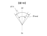
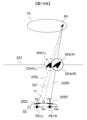
- Figure 1B is a schematic diagram showing the user's viewing angle and the image sensor's viewing angle when viewed from above in the HMDG1 shown in Figure 1A.
- ⁇ hmd is the user's field of view visible from the left display 202L and the right display 202R, and ⁇ 71 represents the angle of view of the image sensor 71.
- the user's field of view ⁇ hmd and the camera angle of view ⁇ 71 are assumed to be approximately equal.
- FIG. 2 is a diagram showing the hardware configuration of the HMD according to this embodiment.
- the HMDG 1 is composed of a main control device 2, a system bus 3, a storage device 4, a sensor device 5, a communication processing device 6, a video processing device 7, an audio processing device 8, an operation input device 9, a gaze detection device 10, and a battery and charging circuit (not shown).
- the main control device 2 is a microprocessor unit that controls the entire HMDG 1 according to a predetermined operating program, and is mainly responsible for input from the user of the HMDG 1, sending and receiving information to and from a management server S1 outside the HMDG 1 in response to that information, controlling the system to process the AR system based on that information, and generating and controlling the display of images to be displayed.
- the system bus 3 is a data communication path for sending and receiving various commands and data between the main control device 2 and each component block within the HMDG 1.
- the storage device 4 includes a program storage area 41 that stores programs for controlling the operation of the HMDG 1, a data storage area 42 that stores various data including operation setting values, detection values of the sensor device 5, images for display, characters, etc., and a rewritable work area 43 such as a work area used for various program operations.
- the storage device 4 may also store operating programs downloaded from a network and various data created by the operating programs. It may also store content such as video, still images, and audio downloaded from a network. It may also store data such as video and still images captured using the imaging function.
- the storage device 4 is able to retain the stored information even when no external power is being supplied to the HMDG 1. Therefore, for example, devices such as flash memory, semiconductor element memory such as an SSD (Solid State Drive), or a magnetic disk drive such as an HDD (Hard Disc Drive) may be used. Furthermore, it is preferable that the operating programs stored in the storage device 4 can be updated and their functions expanded by a download process from each server device on the network.
- devices such as flash memory, semiconductor element memory such as an SSD (Solid State Drive), or a magnetic disk drive such as an HDD (Hard Disc Drive) may be used.
- the operating programs stored in the storage device 4 can be updated and their functions expanded by a download process from each server device on the network.
- the sensor device 5 is made up of various sensors for detecting the state of the HMDG1.
- the sensor device 5 includes a positioning sensor 51 that measures the position in world coordinates, for example using GPS (Global Positioning System), a geomagnetic sensor 52 constituting a so-called motion sensor that detects movement, a distance measurement sensor 53 that measures the distance to a measurement target point, an acceleration sensor 54, and a gyro sensor 55. These sensors make it possible to detect the position, inclination, direction, movement, etc. of the HMDG1, as well as the distance to an object that the user is looking at.
- the HMDG1 may also be equipped with other sensors, such as an illuminance sensor, a proximity sensor, a biometric authentication sensor, etc.
- the communications processing device 6 includes a LAN (Local Area Network) communication device 61, a mobile wireless communication device 62, and a close-proximity wireless communication device 63.
- LAN Local Area Network
- the LAN communication device 61 is connected to a network such as the Internet via an access point or a wireless router, and transmits and receives data to and from a server on the network.
- the connection to the access point or wireless router may be made wirelessly via Wi-Fi (registered trademark) or the like.
- the mobile wireless communication device 62 performs telephone communication (calls) and data transmission and reception through wireless communication with a base station of a mobile wireless communication network. Communication with a base station etc. may be performed using other communication methods such as the W-CDMA (Wideband Code Division Multiple Access) (registered trademark) system, the GSM (registered trademark) (Global System for Mobile communications) system, the LTE (Long Term Evolution) system, or 5G.
- W-CDMA Wideband Code Division Multiple Access
- GSM registered trademark
- LTE Long Term Evolution
- the LAN communication device 61 and the mobile wireless communication device 62 each include an encoding circuit, a decoding circuit, an antenna, etc.
- the close-proximity wireless communication device 63 has a communication function of the BlueTooth (registered trademark) method, but this is not limited to this, and other communication methods such as infrared communication may also be used.
- BlueTooth registered trademark
- the image processing device 7 is composed of an image sensor 71, a video processor 73, a right display 202R, a left display 202L, a right light reduction element 212R, and a left light reduction element 212L.
- the imaging sensor 71 obtains visible image data of the surroundings and objects by converting the visible light input from the lens into an electrical signal using electronic devices such as a CCD (Charge Coupled Device) or CMOS (Complementary Metal Oxide Semiconductor) sensor.
- electronic devices such as a CCD (Charge Coupled Device) or CMOS (Complementary Metal Oxide Semiconductor) sensor.
- the right display 202R and the left display 202L are transmissive displays that use, for example, a reflective volume phase holographic optical element (HOE), and display images by illuminating the display surfaces of the right display 202R and the left display 202L.
- the right display 202R and the left display 202L are equipped with a video RAM (not shown). Images are then displayed on the display surfaces based on the image data input to the video RAM.
- the image sensor 71 captures an image of the gesture.
- the gesture is detected by the video processor 73 and main control device 2, and operations such as display control instructions and display position specification can be performed.
- a TOF (Time Of Flight) sensor may be used in the distance measurement sensor 53 to obtain a distance image. In this case, the gesture detection performance can be improved by using the distance image and the visible image from the image sensor 71 together.
- a drag operation is an operation of moving any object, such as an image or a menu displayed on the right display 202R or the left display 202L, while touching it with a finger
- a flick operation is an operation of moving a finger on the screen by flicking it.
- the video processor 73 also detects the image features mentioned above.
- the distance sensor 53 is called LiDAR (Light Detection And Ranging), and measures the scattered light from a pulsed laser to measure the distance to a distant object, making it possible to measure distance when the object the user is looking at is far away.
- the distance sensor may be configured with a radar that emits radio waves or sound waves instead of light. It may also be a method of acquiring distance images using a TOF sensor.
- LiDAR can also scan the surroundings and generate a three-dimensional spatial map using the output of the sensor device 5 and image processing device 7 described above.
- the imaging sensor 71 may also be configured with a stereo camera.
- the distance to the target object can be obtained from the parallax between the stereo cameras, in the same way as with a TOF sensor.
- the stereo camera and TOF sensor may also serve as the distance measurement sensor 53.
- the imaging sensor 71 may be configured with multiple cameras, one for gesture detection and one for capturing images of enlarged objects.
- the gesture detection camera can capture images at a relatively wide angle, while the camera for capturing images of enlarged objects can be used for telephoto shooting.
- the audio processing device 8 is composed of an audio input/output unit 81, a voice recognition unit 82, an audio decoder 83, and an audio equalizer 84.
- the audio input of the audio input/output unit 81 is a microphone (not shown), which converts the user's voice and surrounding sounds into audio data and inputs it.
- the audio output of the audio input/output unit 81 is a stereo speaker or earphones (not shown), which outputs audio information required by the user.
- the voice recognition unit 82 analyzes the input voice information and performs processing to extract instruction commands, etc. It may be equipped with a processor dedicated to voice recognition, or may be realized as a function executed by the main control device 2.
- the audio decoder 83 has a function for performing decoding processing (audio synthesis processing) of the encoded audio signal as necessary, and a three-dimensional audio processing function according to the transmission characteristics of the audio. It performs decoding processing (audio synthesis processing) of the encoded audio signal.
- the audio equalizer 84 performs equalization processing and three-dimensional audio processing according to the transmission characteristics of the audio, and the processed audio is output from the audio input/output unit 81.
- the voice recognition unit 82 of the voice processing device 8 may also be used to operate the HMDG 1 using voice commands for operation instructions.
- the operation input device 9 is an instruction input unit that inputs operation instructions to the HMDG 1.
- the operation input device 9 may be configured using an operation key consisting of an array of button switches or the like (not shown), or may further include other operation devices.
- the HMDG 1 may be operated using a separate mobile terminal device connected by wired or wireless communication using the communication processing device 6.
- the gaze detection device 10 detects the gaze direction of a user wearing the HMDG 1.
- the gaze detection method of the right gaze detector 1001R and the left gaze detector 1001L includes shining invisible light (such as infrared light) onto the user's eyes and obtaining a pupil image from the captured image through image processing, but there are no particular limitations on the detection method.
- the example configuration of the HMDG1 shown in FIG. 2 includes many components that are not essential to this embodiment, but the effects of this embodiment are not diminished even if these components are not included.
- components not shown such as a digital broadcast receiving function and an electronic money payment function, may also be added.
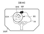
- FIGS. 3A and 3B are schematic diagrams showing an overview of the image viewed by a user through an HMD, which is an example of a mobile information terminal according to this embodiment.
- FIG. 3A The image shown in Fig. 3A is a view seen by a user wearing the HMDG1 through the right display 202R, including a tree TR, birdhouses BH installed on the branches and trunk of the tree TR, a bird BD resting on the branch of the tree TR, and a branch BR near the apex of the tree TR.
- This operating state in which an image that is almost the same as the view seen when the user is not wearing the HMDG1, is called the normal mode.
- This operating state does not display an enlarged image, as opposed to the enlarged display mode that displays an enlarged image, which will be described later.
- the following describes the various enlarged display modes of a mobile information terminal suitable for applications such as allowing users to observe beehives BH on trees TR.
- the object to be enlarged and displayed in the scenery seen through the right display 202R and the left display 202L is referred to as the enlarged display area
- the area in which an enlarged image of the enlarged object is displayed on the right display 202R and the left display 202L is referred to as the enlarged display area.
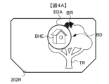
- (First enlarged display mode) 4A and 4B are schematic diagrams showing a first enlarged display mode and a first enlarged target mode in the portable information terminal according to this embodiment.
- the enlarged display area EDA is set to the position of the hive BH, and in the enlarged display mode, when the user wearing the HMDG1 turns his head to the left from the state shown in Figure 3B, the state shown in Figure 4A is that when he turns his head to the right, as shown in Figure 4B.
- the trees TR and other objects visible through the right display 202R appear to move to the right or left.
- the enlarged display area EDA displaying the enlarged image BHE of the beehive BH also moves to the position on the right display 202R where the beehive BH should be visible.
- the display position of the enlarged image BHE shown in Figures 4A and 4B is specified to be approximately the same as the normal display position of the hive BH, which is the object to be enlarged.
- approximately the center of the enlarged display area EDA is assigned to approximately the center of the area in which the hive BH, which is the object to be enlarged, is displayed in normal mode within the display surface of the right display 202R. This is called the first enlarged display mode.
- the enlarged image of the object to be enlarged is displayed in the enlarged display area EDA, and the user can grasp where the object to be enlarged is located within the overall view seen from the right display 202R.
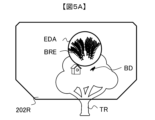
- FIGS. 5A and 5B are schematic diagrams showing the second enlarged display mode in the portable information terminal according to this embodiment.
- the enlarged display area EDA is fixed relative to the right display 202R, and from the state shown in FIG. 3B, the head is turned up as shown in FIG. 5A, and from the state shown in FIG. 3B, the head is turned to the right as shown in FIG. 5B.
- FIG. 5A an enlarged image BRE of a branch BR near the top of a tree TR is displayed in the enlarged display area EDA.
- Fig. 5B an enlarged image BDE of a bird BD to the right of a birdhouse BH is displayed in the enlarged display area EDA.
- the object to be enlarged is an object on the extension of the line of sight of the user looking at the enlarged display area EDA.
- the branch BR is on the extension of the line of sight, so the branch BR is the object to be enlarged.
- the object to be enlarged changes to the bird BD in accordance with the head movement, and an enlarged image BDE of the bird BD is displayed.
- the object to be enlarged is an object on an extension of the enlarged display area EDA, and the enlarged image is displayed in the enlarged display area EDA at a position specified in a coordinate system (local coordinate system) fixed to the HMDG1.
- a coordinate system local coordinate system
- the second enlarged display mode is suited to use like a telescope, where you want to always see a magnified view in the direction the user is facing, and is convenient because the enlarged display area EDA can be placed at any position on the right display 202R.
- the enlarged display area on the left display 202L can be displayed with a three-dimensional feel by providing a left-right parallax in the display position that corresponds to the distance to the actual target to be enlarged.
- the enlarged display area is based on the right or left display can be set by the user, or it can be set based on the user's dominant eye.
- the first enlarged display mode mentioned above is further divided into two modes.
- the enlargement target can be specified in the real world coordinate system (world coordinate system).
- the position of the fixed hive BH at world coordinates (X0, Y0, Z0) is always the enlargement target, so as shown in Fig. 4A and Fig. 4B, the enlarged display area EDA moves on the right display 202R to a position where the hive BH at world coordinates (X0, Y0, Z0) can be seen according to the movement of the user's head. This is called the first enlargement target mode.
- the first zoom display mode and first zoom target mode are useful when you want to zoom in on a specified fixed location in the distance, for example when lying in wait to observe a bird BD.
- the mode in which the enlarged display area EDA is displayed so as to follow the movement of the enlarged target is referred to as the first enlarged display mode and second enlarged target mode.
- FIGS. 6A and 6B are schematic diagrams showing the first enlarged display mode and the second enlarged target mode in a mobile information terminal according to this embodiment.
- Figure 6A shows a state in which a bird BD is specified as the object to be enlarged, and an enlarged image BDE is displayed in the enlarged display area EDA.
- Figure 6B shows the display state when the user moves their head to the left from the state shown in Figure 6A, and the bird BD to be enlarged moves to the right side of the tree TR. In this way, the enlarged display area EDA is displayed so that it moves in position on the right display 202R in accordance with the movement of the bird BD.
- the first magnified display mode and the second magnified target mode when a user wishes to enlarge a specified distant object, the first magnified target mode does not require the user to carefully turn their head towards the object to be enlarged.
- the user when enlarging a moving animal or object, such as a bird, the user can always keep track of the object to be enlarged and can simultaneously grasp the position of the object being enlarged within the overall scenery being viewed by the user.
- the operation will be the same as in the first enlarged object mode fixed in world coordinates, unless the nest box BH is a fixed object and does not move.
- first enlarged display mode & first enlarged target mode, first enlarged display mode & second enlarged target mode, and second enlarged display mode mentioned above are implemented by selecting one of these modes on the HMDG1, or the modes are specified in an initial setting menu (not shown).
- FIG. 7A is a schematic diagram showing switching to the enlarged display mode.
- Figure 7A shows a state in which the hand (HND) of a user wearing the HMDG1 is imaged in front of the scenery viewed by the user.
- a gesture operation of making a circle with the hand HND is used as a user input operation to indicate that the user wishes to enlarge the display.
- the video processor 73 and main control device 2 detect this gesture and the main control device 2 determines that an instruction to enlarge the display has been given, it switches control to display the enlarged display area EDA in a specified position (for example, the center of the right display 202R) as shown in Fig. 7B.
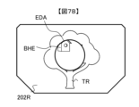
- FIG. 7B is a schematic diagram showing the state of the right display 202R after the enlarged display instruction is received.
- the enlarged display area EDA shows the scenery within the field of view on an extension of the enlarged display area EDA, displayed at the initial magnification and size (area) of the enlarged display area EDA.
- an example of a circular enlarged display area EDA is shown, it may also be rectangular or the like, and there are no particular limitations.
- FIG. 7C is a schematic diagram showing a gesture by the user to specify the display position of the enlarged display area EDA.
- the user holds out one finger of the hand HND and drags it so that it touches the displayed enlarged display area EDA, making a gesture to specify that the enlarged image BHE to be displayed is approximately in the center of the enlarged display area EDA.
- the border of the enlarged display area EDA can be pinched and moved.
- the user gestures by lowering their hand away from the field of view of the right display 202R, thereby designating the image approximately in the center of the enlarged display area EDA at the time of lowering the hand as the image to be enlarged, and the designated display position of the enlarged display area EDA is confirmed.
- the user's specification of the object to be enlarged can be accepted by the main control device 2 using the image feature detection function of the video processor 73.
- the user specifies the size of the enlarged display area EDA (size of the circle) and the enlargement rate of the display object.
- FIG. 7D is a schematic diagram showing a gesture by the user specifying the size of the enlarged display area EDA and the enlargement ratio at the time of displaying the enlarged object.
- the user holds their hand HND with two fingers (thumb and index finger in this example) over the enlarged display area EDA, and by changing the distance between the thumb and index finger, they can adjust the size of the enlarged display area EDA, and by moving the held hand HND closer to or farther away from the HMDG1 (for example, moving it closer to enlarge, moving it farther away to reduce), they can vary the magnification ratio of the enlarged image BHE to make the desired designation.
- the audio equalizer 84 amplifies the audio of the object to be magnified according to the distance to the object and the magnification ratio, and performs high-frequency equalization and ambient sound and noise suppression control, thereby achieving an effect that emphasizes the sense of realism as if the audio was being heard from a position close to the magnified object.
- the user can switch to the enlarged display mode, specify the display position of the enlarged display area, and specify the size and magnification rate of the enlarged display area, and display in the enlarged display mode and enlargement target mode that is pre-implemented in the HMDG1 or pre-set in the menu.
- the enlarged display mode and the enlargement target mode can also be specified in the process of switching to the enlarged display mode and specifying the display position of the enlarged display area and the size and enlargement rate of the enlarged display area.
- FIG. 7C is a schematic diagram showing a gesture by the user to specify the display position of the enlarged display area EDA.
- the user holds out one finger of the hand HND and drags it so that it touches the displayed enlarged display area EDA, making a gesture to specify that the enlarged image BHE to be displayed is approximately in the center of the enlarged display area EDA.
- the first enlarged display mode and the first enlarged target mode can be specified with one finger of the hand HND during the drag operation, and the display position of the enlarged display area EDA can be specified by moving the hand HND during the drag operation.
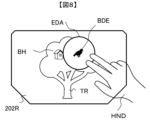
- FIG. 8 is a schematic diagram showing a method for specifying the display position of the enlarged display area EDA and the object to be enlarged in the first enlarged display mode and the second enlarged object mode.
- the user specifies the first enlarged display mode and second enlarged object mode.
- the user holds out two fingers of the hand HND and drags them as if touching the displayed enlarged display area EDA, specifying with a gesture that the enlarged image BDE to be displayed is near the center of the enlarged display area EDA.
- the first enlarged display mode and second enlarged object mode can be specified with two fingers of the hand HND during the drag operation, and the display position of the enlarged display area EDA can be specified by moving the hand HND during the drag operation.
- the user lowers the hand that was raised in the gesture so that it is away from the field of view of the right display 202R, thereby finalizing the first enlarged display mode and the second enlarged target mode, the specification of the target to be enlarged, and the specification of the display position of the enlarged display area EDA.
- FIG. 9 is a schematic diagram showing a method for specifying the display position of the enlarged display area EDA and an object to be enlarged in the second enlarged display mode.
- the user specifies the second enlarged display mode when, for example, he or she wishes to fix the display position of the enlarged display area EDA to the top of the right display 202R.
- the user holds out three fingers of the hand HND and uses a gesture to drag and touch the displayed enlarged display area EDA so that the enlarged display area EDA is at the top of the right display 202R.
- the second display mode is specified with three fingers of the hand HND during the drag operation, and the display position of the enlarged display area EDA can be specified by moving the hand HND during the drag operation.
- the user moves the hand that was raised in the gesture away from the field of view of the right display 202R, thereby finalizing the second enlarged display mode, the specification of the object to be enlarged, and the specification of the display position of the enlarged display area EDA.
- the gesture of holding up three fingers may be difficult for some people, so before starting the dragging action, you can temporarily remove your hand from the field of view of the right display 202R, then hold your hand HND in a circular shape again and change its orientation to substitute for the three-finger gesture dragging operation.
- the second enlarged display mode may be specified by a one-finger dragging operation instead of a three-finger dragging operation.
- the size of the enlarged display area may be set by changing the size of the ring of the hand HND.
- the enlargement rate may be set by moving the ring-shaped hand HND closer to or farther away from the face.
- the first enlarged display mode & first enlarged target mode As described above, with this specification method, it is possible to specify the first enlarged display mode & first enlarged target mode, the first enlarged display mode & second enlarged target mode, and the second enlarged display mode by the number of fingers used during the drag gesture.
- FIG. 10A is a schematic diagram showing an image captured by the imaging sensor 71 of the HMDG1.
- CIM is the captured image of the scene shown in FIG. 3A, which has been captured and processed by the video processor 73.
- the field of view ⁇ hmd and the camera angle of view ⁇ 71 are approximately the same, so the scene in FIG. 3A is the captured image CIM as is.
- the user's gestures, the recognition of the enlarged target, and the tracking process, which were mentioned above, are executed by the main control device 2 performing recognition processing on the captured image CIM.
- EIM be the designated image showing the object to be enlarged that the user has arbitrarily specified with the previous gesture. For example, if the object to be enlarged is the hive BH, then the designated image EIM is the image of the hive BH. In the HMDG1, the designated image EIM specified by the user is enlarged and displayed from this captured image CIM.
- FIG. 10B is a schematic diagram showing the enlarged display area EDA displayed on the right display 202R, where PO represents the position at which the specified image EIM to be enlarged is visible on the right display 202R (the hive BH in the example of FIG. 10B), and EDAD represents the size of the enlarged display area EDA.
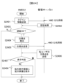
- FIG. 11 is a flowchart showing the procedure for determining whether to switch from normal mode to each enlarged display mode or each enlargement target mode.
- the main control device 2 acquires the captured image CIM captured by the image sensor 71 and processed by the video processor 73.
- step S1102 The main control device 2 uses image processing to determine whether the acquired image shows the user's hand HND and whether it is a circular gesture. If the answer is Yes, the process proceeds to step S1103. If the answer is No, the process ends, the mode becomes normal, and the process proceeds again to step S1101.
- An enlarged display area EDA is set at a predetermined display position (e.g., the center) on the right display 202R and the left display 202L, and the designated image EIM to be enlarged (e.g., the center of the captured image CIM) is enlarged and displayed within the enlarged display area EDA.
- a predetermined display position e.g., the center
- the designated image EIM to be enlarged e.g., the center of the captured image CIM
- S1104 The main control device 2 acquires a new captured image CIM that has been captured by the imaging sensor 71 and processed.
- S1105 As shown in Figures 7C, 8, and 9, when the user drags his/her hand HND, the main control unit 2 moves the enlarged display area EDA and the designated image EIM to be enlarged in accordance with the drag operation, and performs display control according to the movement. Furthermore, as shown in Figure 7D, when the user holds his/her hand HND with two fingers (thumb and index finger in this example) over the enlarged display area EDA and makes a gesture to change the distance between the thumb and index finger, the main control unit 2 accepts the size adjustment of the enlarged display area EDA in accordance with the gesture movement.
- the main control unit 2 accepts the operation of specifying the magnification rate ER of the enlarged image BHE.
- S1106 The main control device 2 determines whether the user has quickly lowered the hand HND (at a speed equal to or faster than a predetermined speed) based on whether the hand HND has disappeared from the field of view of the image sensor 71, based on the image captured by the image sensor 71. If the answer is yes, proceed to S1107; if the answer is no, return to S1104.
- the main control device 2 calculates the world coordinates (X1, Y1, Z1) of the image of the enlarged object (assumed to be EIM1) that was specified immediately before it was determined in step S1106 that the hand was lowered.
- the world coordinates of the enlarged object are calculated by obtaining the position and imaging direction of the imaging sensor from the positioning sensor 51 and the geomagnetic sensor 52, and the distance from the distance measuring sensor to the enlarged object.
- the main control device 2 stores the image EIM1 at approximately the center of the enlarged display area EDA, the enlargement ratio ER1, the size EDAD1 of the enlarged display area, and the position PO1 on the right display 202R of the enlargement target, which were specified immediately before it was determined in step S1106 that the hand was lowered, as the initial image EIMi, the enlargement ratio ER1, the size EDAD, and the position PO of the enlargement target, respectively.
- step S1109 The main control device 2 determines the display mode and enlargement target mode designation based on the number of fingers on the hand HND during the dragging motion immediately before it is determined in step S1106 that the hand has been lowered. If there is one finger, the process proceeds to step S1110; if there are two fingers, the process proceeds to step S1111; if there are three fingers, the process proceeds to step S1112.
- the main control device 2 performs display control for the first enlarged display mode and the first enlarged target mode.
- the main control device 2 performs display control for the first enlarged display mode and the second enlarged target mode.
- S1112 The main control device 2 performs display control for the second enlarged display mode.
- FIG. 12 is a flowchart showing the display control of the first enlarged display mode and the first enlarged target mode in the main control device 2 of the HMDG 1.
- the main control device 2 acquires the captured image CIM captured by the imaging sensor 71 and processed.
- the main control device 2 acquires the outputs of the motion sensors (geomagnetic sensor 52, acceleration sensor 54, gyro sensor 55), as well as the outputs of the positioning sensor 51, distance measurement sensor 53, right gaze detector 1001R, and left gaze detector 1001L.
- the main control device 2 acquiring these outputs corresponds to detecting the user's movements.
- the main control device 2 calculates a new position of the enlarged object within the display surface after it has been moved, based on the world coordinates (X1, Y1, Z1) of the object to be enlarged determined in step 1107, the position of the HMDG1 determined by the positioning sensor 51, and information obtained from the motion sensor output, the right gaze detector 1001R and the left gaze detector 1001L, and the distance measurement sensor 53, so as to offset the movement of the display and the eyes.
- the position POrt at which the object to be enlarged viewed on the right display 202R is visible to the user is calculated, and stored as position PO.
- the main control device 2 stores the image EIMfix of the object on the captured image CIM located at world coordinates (X1, Y1, Z1) as the specified image EIM.
- the target to be enlarged specified in step S1108 in the mobile information terminal according to this embodiment is fixed at world coordinates (X1, Y1, Z1). Furthermore, since the position PO is constantly updated by the motion sensor output and the positioning sensor 51, even if the user walks around or moves his/her head, the enlarged display area EDA is superimposed and displayed at a position on the right display 202R where the target to be enlarged is always visible to the user.
- FIG. 13 is a flowchart showing the display control of the first enlarged display mode and the second enlarged target mode in the main control device 2 of the HMDG 1.
- the main control device 2 acquires the captured image CIM that has been captured by the imaging sensor 71 and processed.
- the main control device 2 stores the center position POscan of the highly correlated image on the captured image CIM obtained by scanning as the position PO, and stores the image EIMrt at that position as the designated image EIM to be enlarged.
- the image to be enlarged is constantly recognized by image processing as an image that has a high correlation with the initial image EIMi of the enlarged object stored at the time the first enlarged display mode and the second enlarged object mode were specified, and the position PO of the specified image EIM of the enlarged object on the right display 202R is also constantly updated. Therefore, by controlling the display of the enlarged display area EDA according to the position PO, even if the enlarged object moves, the enlarged display area EDA can be superimposed and displayed to follow the movement.
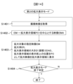
- FIG. 14 is a flowchart showing the display control of the second enlarged display mode in the main control device 2 of the HMDG 1.
- the main control device 2 acquires the captured image CIM that has been captured by the imaging sensor 71 and processed.
- the position of the enlarged display area EDA on the right display 202R that is stored when the second enlarged display mode is specified is fixed, and the object that is on the extension of that enlarged display area EDA is the object to be enlarged, so it can be used like a telescope.
- the determination of whether the conditions for ending each display mode in steps S1206, S1305, and S1404 are met may be determined, for example, by detecting that the specified enlargement target has disappeared from the captured image CIM, detecting that the enlarged display area EDA has reached the periphery of the right display 202R, or detecting that a specified ending gesture or operation (not shown) has been performed by the user.
- the object to be enlarged may be stored, and when the object to be enlarged returns to the captured image CIM, the enlarged display area EDA may be redisplayed, the enlarged display may remain terminated, or it may be determined in advance in the initial settings of the mobile information terminal whether to resume or terminate the display.
- FIG. 15 shows a gesture action for restoring the enlarged display state after the enlarged display has ended.
- the enlarged display is set to end by default, it may be possible to restore the enlarged display state before it was ended by a gesture such as making a circular movement of the index finger of the hand (HND).
- a gesture such as making a circular movement of the index finger of the hand (HND).
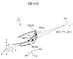
- FIG. 16A is a schematic diagram showing the concept of how the HMDG1 calculates the world coordinates of the enlargement target in step S1107 (FIG. 11).
- PE1R represents the right eye of the user wearing the HMDG1
- PE1L represents the left eye.
- the gaze of the right eye PE1R and the left eye PE1L is assumed to be fixed on the magnified object, for example, a birdhouse on a tree TR.
- the X-axis, Y-axis, and Z-axis represent the world coordinate system.
- the position of HMDG1 (Xhmd, Yhmd, Zhmd) is obtained from positioning sensor 51 as data in a world coordinate system such as the World Geodetic System.
- the direction ⁇ of HMDG1 is obtained from geomagnetic sensor 52.
- the inclination ⁇ of HMDG1 with respect to the vertical axis is obtained from acceleration sensor 54.
- the line of sight direction is obtained from right line of sight detector 1001R and left line of sight detector 1001L.
- the distance to the beehive on tree TR is obtained from distance measurement sensor 53.
- the distance and direction to the position of the target to be enlarged can be obtained from the position of HMDG1 (Xhmd, Yhmd, Zhmd) and each sensor information, so the world coordinate position of the hive on the tree TR, which is the target to be enlarged, can be calculated.
- the components of the HMDG1 such as the image sensor 71, left display 202L, and right display 202R, are fixedly arranged in predetermined positions and orientations on the housing G10 of the HMDG1 (see Figure 1), so even if the HMDG1 moves, the position and tilt information of the HMDG1 can be calculated.
- the positions of the right eye P1ER and left eye P1EL can be detected by the gaze detection device 10 relative to the HMDG1, so their positions in world coordinates can be found.
- the Xer, Yer, and Zer axes indicate the right eye coordinate system, which is a local coordinate system seen from the right eye P1ER.
- the coordinates (X1, Y1, Z1) of the hive in the world coordinate system can be converted to coordinates (Xer1, Yer1, Zer1) of the right eye coordinate system by the coordinate conversion of the following equation (1).
- the origin position of the right eye coordinate system in the world coordinate system i.e., the position of the right eye P1ER, is set to (Xe1r, Ye1r, Ze1r).
- the transformation from the right eye coordinate system to the world coordinate system can also be calculated by the above inverse matrix operation using the following equation (2).
- the display image of the right display 202R is seen on a virtual image plane located at a predetermined distance near from the right eye P1ER.
- the coordinates (Xer1, Yer1, Zer1) of the hive in the three-dimensional right eye coordinate system are perspectively transformed into the coordinates (Xdr1, Ydr1) of the hive in the two-dimensional right display coordinate system by the following equations (3) and (4).
- the right display coordinate system has its origin at the center of the display area on the virtual image plane, with the Xd axis pointing to the right and the Yd axis pointing downward.
- the conversion from the two-dimensional right display system on the virtual image plane to the two-dimensional display coordinate system of the planar display element that constitutes the right display 202R depends on the optical configuration within the right display 202R, so a detailed explanation will be omitted.
- the two-dimensional display coordinate system of the planar display element is one in which the display size on the virtual image plane is proportionally reduced to the display size of the planar display element.
- the right eye P1ER can be fixed relatively to the right display 202R and a simple calculation can be performed. In this case, the amount of movement of the right eye P1ER can be regarded as the amount of movement of the right display 202R.
- the conversion between the image capture coordinate system, which is a local coordinate system with the image capture sensor 71 as its origin, and the world coordinate system can also be calculated using a similar formula. Furthermore, the conversion between the image capture coordinate system and the right eye coordinate system can be performed directly without conversion to the world coordinate system, because the positional relationship between the image capture sensor 71 of the HMDG1 and the right and left displays 202R and 202L is fixed.
- the enlarged target is fixed in world coordinates, so in order to align the enlarged display area with the visible position of the enlarged target, it is necessary to calculate the visible direction of the enlarged target in the left and right eye coordinate systems based on the position and orientation information of the HMDG1.
- the enlarged target is tracked in the captured image, so its position on the capture coordinate system can be grasped by the video processor 73 and main control device 2 (corresponding to the image processing unit).
- the capture coordinate system and the left and right eye coordinate systems can be directly converted to each other without going through the world coordinate system. Therefore, the enlarged display area can be adjusted to the visible position of the enlarged target without acquiring the position and orientation information of the HMDG 1 in real time.
- FIG. 16B is a schematic diagram showing the relationship between the object to be enlarged and the enlarged display area on the display.
- the direction in which the bird BD is seen from the right eye PE1R is indicated by 222R
- the direction in which the bird BD is seen from the left eye PE1L is indicated by 222L
- the direction in which the image sensor 71 images the bird BD is indicated by 221.
- the left display 202L and the right display 202R indicate a virtual image display surface 223 displayed to the left eye PE1L and the right eye PE1R.
- An enlarged display area EDA(R) is set around the intersection of the virtual image display surface 223 and the direction 222R in which the bird BD is visible.
- An enlarged image BDE(R) of the bird BD is displayed in the enlarged display area EDA(R).
- the left eye is similarly displayed, but because the left display 202L and the right display 202R are misaligned, parallax occurs between the enlarged display areas EDA(L) and EDA(R).
- FIG. 17 is a schematic diagram showing the structure of the right display 202R and right light reduction element 212R of the mobile information terminal according to this embodiment.
- the right display 202R reflects the projected image from the projection device 2021 (organic EL, liquid crystal, etc.) with a prism, and changes the optical path with the display image light 2123 at the optical combiner of the half mirror 2022, allowing the user to view it.
- the user can also view external light 2124 through the half mirror 2022, and is configured with a so-called general see-through optical system.
- the right light reducing element 212R is composed of an element such as liquid crystal or electrophoretic toner that can control the light transmittance on a pixel-by-pixel basis, but is not limited thereto and may be any element that can control the light transmittance on a pixel-by-pixel basis.
- a black matrix that does not transmit light exists between the pixels of the right light reducing element 212R.
- the half mirror 2022 is composed of a Fresnel mirror or a diffraction grating, a black matrix area that does not transmit light is generated.
- the video processor 73 generates a video signal that is superimposed on the outside scenery of the right display 202R. In the same figure, as an example, a right display video signal 202RS that displays an enlarged image in the enlarged display area EDA is generated.
- the video processor 73 generates a dimming signal 212RS to reduce the brightness of the enlarged display area EDA.
- a dimming signal 212RS to reduce the brightness of the enlarged display area EDA.
- the video processor 73 may generate a dimming signal 212RS that not only reduces the brightness of the enlarged display area EDA, but also slightly reduces the brightness of the surrounding area.
- FIG. 18 is a schematic diagram showing the right display 202R as a result of driving the projection device of the right display 202R with a right display video signal 202RS and driving the right light reduction element 212R with a dimming signal 212RS that also reduces the external brightness around the enlarged display area EDA.
- the number of pixels of the right light-reducing element 212R may be less than the number of pixels of the right display 202R, for example, about 1/10 or less.
- an object within the field of view of the user via a mobile information terminal can be designated as an object to be enlarged, and the enlarged object can be enlarged and displayed on the mobile information terminal.
- the enlarged and displayed object to be enlarged is displayed superimposed on the position of the object before enlargement in the user's field of view, so that the user can also know where the object to be enlarged is located in the field of view.
- a mobile information terminal and a display control method for a mobile information terminal that can simultaneously enlarge and display an object as desired by the user and grasp the position of that object within the overall scene.
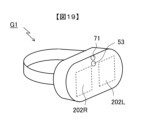
- Second Embodiment Fig. 19 is a configuration diagram showing an example of a video see-through type (non-transmissive type) HMD to which this embodiment is applied.
- the difference from the optical see-through type HMD in Fig. 1A is that the right display 202R and the left display 202L are not transmissive, and the outside scenery is not visible to the user P1 wearing the HMDG1.
- the video see-through is used to display the image captured by the image sensor 71 on the right display 202R and the left display 202L, and as described above, the user can also operate the device with gestures or by operating a keyboard at hand (not shown).
- the hardware configuration shown in FIG. 2 does not require the right light reduction element 212R and the left light reduction element 212L, but the rest is the same as that of an optical see-through type HMD, so they are not shown in the illustration.
- the captured image CIM shown in FIG. 10A is displayed on the right display 202R and the left display 202L, and the enlarged display area EDA is displayed after being superimposed on the captured image CIM by the video processor 73.
- the right light reducing element 212R and the left light reducing element 212L are used to reduce the brightness of the transmitted scenery for the superimposed enlarged display area EDA, but in a video see-through type HMD, the brightness of the captured image CIM is reduced by video signal processing, and then the enlarged display area EDA is superimposed. Other processing is the same as in the optical see-through type HMD.
- a mobile information terminal and a display control method for a mobile information terminal can be provided that allows the user to both enlarge and display the object desired by the user and grasp the position of the object in the overall scene, even with a video see-through (non-transparent) HMD.
- Third Embodiment 20A to 20E are schematic diagrams showing an example in which this embodiment is applied to a tablet-type portable information terminal.
- the portable information terminal according to this embodiment differs from the optical see-through type HMD of FIG. 2A in that while the optical see-through type HMD of FIG. 2A has two displays, a right display 202R and a left display 202L, the portable information terminal according to this embodiment has only one display 202 made of liquid crystal or organic EL, and the outside world view is displayed on the display 202 as a captured image CIM captured by an image sensor 71, just like a video see-through type HMD, and further in that the display 202 is configured with a touch panel laminated thereon.
- the hardware configuration is the same as that of an optical see-through HMD, except that the right light reduction element 212R, left light reduction element 212L, right gaze detector 1001R, and left gaze detector 1001L are not included in the configuration shown in FIG. 2, and therefore is not shown in the figures.
- a tablet terminal which is an example of a mobile information terminal according to this embodiment, is equipped with a touch panel that allows operations to be performed by touching the screen. Therefore, unlike the application example of this embodiment on an HMD, the target to be enlarged, the size of the enlarged display area, and the enlargement ratio are specified by touch operations.
- HND represents the hand of the user wearing the HMDG1.
- ⁇ Switching to enlarged display mode> First, as shown in Fig. 20A, the user taps the display 202 with the hand HND to indicate that he/she wishes to enlarge the display. The tapping action is detected by the video processor 73 and the main control device 2, and the main control device 2 determines that an instruction for enlarged display has been given, and switches control to display the enlarged display area EDA at a predetermined position (for example, the center of the display 202) as shown in Fig. 20B.
- a predetermined position for example, the center of the display 202
- FIG. 20B is a schematic diagram showing the state of the display 202 after the enlarged display instruction is received.
- the enlarged display area EDA shows the image of the captured image CIM that corresponds to the center of the enlarged display area EDA, displayed at the initial magnification and with the initial size (area) of the enlarged display area EDA.
- a circular enlarged display area EDA may also be rectangular or the like, and there are no particular limitations.
- FIG. 20C is a schematic diagram showing an operation in which the user specifies the display position of the enlarged display area EDA.
- the user drags the displayed enlarged display area EDA to specify that the enlarged image BHE to be displayed is located near the center of the enlarged display area EDA.
- the user releases the dragged hand HND from the display 202, thereby finalizing the specification of the image approximately in the center of the enlarged display area EDA as the target for enlargement and the display position of the enlarged display area EDA.
- the user specifies the size of the enlarged display area EDA (size of the circle) and the magnification rate of the display object.
- FIG. 20D is a schematic diagram showing an operation by the user to specify the size of the enlarged display area EDA and the enlargement ratio when the object to be enlarged is displayed.
- the user adjusts the size of the enlarged display area EDA by pinching out two fingers (thumb and index finger in this example) on the frame surrounding the enlarged display area EDA, and then pinches out on the inside of the enlarged display area EDA to change the magnification ratio of the enlarged image BHE to the desired size.
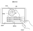
- FIG. 20E is a schematic diagram showing the display of the display 202 for specifying the display mode.
- a menu MENU for selecting each display mode and each enlargement target mode is displayed.
- the user selects the desired display mode and enlargement target mode from this menu MENU by tapping, thereby specifying the display mode.
- the first enlargement target mode may not be implemented, and only the second enlargement target mode may be implemented. In this case, only the first display mode and the second display mode may be implemented.
- This type of user interface is convenient for tablet devices and mobile information terminals such as smartphones, which have touch panels, as it allows you to specify various display mode parameters using the touch panel.
- a mobile information terminal having a single display 202 such as a tablet terminal or a smartphone
- FIG. 21 is a schematic diagram showing a system configuration in which the mobile information terminal according to this embodiment is applied to an AR service.
- the AR system 400 includes HMDG1-G5, which are portable information terminals according to this embodiment, connected to a management server S1 via a base station B1 and a network N1 of a mobile wireless communication network.
- HMDG1-G5 are worn by different users P1-P5 (not shown).
- the management server S1 is a management server that manages the AR service according to this embodiment.
- Service area A1 indicates the range in which this AR service is provided. For example, it represents a service area in which this AR service is provided within a specific range in a particular tourist destination.
- the management server S1 manages multiple pieces of information acquired via the network N1.
- the information managed by the management server S1 includes, for example, account information on the users of each of the HMDG1 to HMDG5, the location information and gaze point information of the HMDG1 acquired via the base station B1, and the video information and comment information uploaded by each user in this AR service.
- Information about each user includes user information (user identification information) such as nicknames and handle names, including name, and user attribute information (age, hobbies, preferences, etc.).
- Registration may be done by inputting the information as a profile on an application program used by the HMDG1 to receive the AR system services, or it may be automatically collected or generated from other application programs used by the user or from the user's behavioral history, or it may be linked to information registered in other application programs.
- the user attribute information may be stored in either the HMD or the management server S1.
- this embodiment shows an example of HMDG1 to HMDG5 worn by five users as shown in FIG. 21, but there is no limit to the number of users.
- FIG. 21 shows an example in which HMDG1 to HMDG5 are connected to this AR service via base station B1
- HMDG1 to HMDG5 may also be configured to be connected to network N1 via a wireless router (not shown).
- Figure 22 is a schematic diagram showing the environment in which the services of this AR system are used.
- the diagram shows clouds CL, an airplane AP in flight, an airship AS in flight, a bird BDF in flight, an area AS1 near the airship AS, and an area AP1 near the airplane AP.
- User P1 is wearing HMDG1
- user P2 is wearing HMDG2
- user P3 is wearing HMDG3.
- Each of users P1 to P3 is shown to be in service area A1.
- user P1 is gazing at the flying bird BDF, while users P2 and P3 are gazing within the range of AS1.
- the world coordinates (Xas, Yas, Zas) of the airship AS that user P2 is gazing at are notified to user P1 via the AR system.
- FIG. 23 is a schematic diagram showing an enlarged image ASE of the airship AS that another user P2 is gazing at in the enlarged display area EDA.
- the object that other users are gazing at is displayed enlarged in the scenery shared by multiple users, so the object that other users are gazing at is not overlooked and the situation of gazing at it can be shared.
- the object that user P1 is gazing at (for example, a flying bird BDF) can also be transmitted in its world coordinates to other users via the AR system, allowing the situation of gazing at the object and the object to be shared.
- Figure 24 is a flowchart showing the processing steps of the HMD and the management server.
- the main control device 2 of HMDG1 transmits authentication information, such as the user ID, password, coordinates of HMDG1, and information on paid service charges, to the management server S1.
- the management server S1 transmits the authentication result indicating whether the position (coordinates) of the HMDG1 received is within the service area A1 of the AR system 400, and whether the user ID and password match the information registered in advance.
- the main control device 2 of the HMDG1 detects the gaze point (world coordinates) of the user P1.
- the main control device 2 of the HMDG1 further transmits the gaze point detected in S2405 to the management server S1 along with the position of the HMDG1.
- the management server S1 broadcasts the gaze point information received from HMDG1 and HMDG2 worn by each user to each HMD.
- the main control device 2 of the HMDG1 performs a display determination as to whether the received gaze point of user P2 is within the field of view of the right display 202R.
- S2408 If it is determined in S2407 that there is a point of interest to be displayed, the main control device 2 of the HMDG1 performs processing to enlarge and display the image of the point of interest in the enlarged display area EDA.
- the enlarged display mode, enlargement target mode, changes to the enlarged display position, changes to the enlarged display area size, changes to the enlargement rate, etc. are the same as in the first embodiment, so detailed explanations will be omitted.
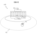
- Figure 25 is a schematic diagram showing the environment in which the services of this AR system are used.
- the figure shows ruins HR in a tourist spot, a vase R1 that is part of ruins HR, a statue R2 that is part of ruins HR, a superstructure R3 that is part of ruins HR, and a service area A2 where this AR system is provided.
- a tourism business providing an AR system service is assumed to have registered the world coordinates of an important archaeological site (e.g., jar R1) in the management server S1.
- an important archaeological site e.g., jar R1
- Figure 26 is a schematic diagram showing an example of an HMD display in the service of this AR system.
- the right display 202R of the HMDG1 worn by the user P1 displays an enlarged image R1E of a vase R1 (see FIG. 25) registered in the management server S1 by the tourism business operator in an enlarged display area EDA.
- FIG. 27 is a flowchart showing the processing steps of the HMD and management server shown in FIG. 26.
- the management server S1 broadcasts the world coordinates of the ruins registered by the tourism business operator.
- the enlarged display mode, enlargement target mode, enlarged display position, enlarged display area size, and enlargement rate can be changed in the same way as in the first embodiment, and detailed explanations will be omitted.
- the point of gaze that another person is gazing at can be enlarged and displayed on the mobile information terminal that the user is using.
- the present invention is not limited to the above-mentioned embodiment, but includes various modified examples.
- the above-mentioned embodiment has been described in detail to clearly explain the present invention, and is not necessarily limited to having all of the configurations described.
- each of the above configurations may be configured in part or in whole as hardware, or may be configured to be realized by executing a program on a processor.
- control lines and information lines shown are those considered necessary for the explanation, and do not necessarily show all control lines and information lines in the product. In reality, it can be considered that almost all of the configurations are interconnected.
Landscapes
- Engineering & Computer Science (AREA)
- General Engineering & Computer Science (AREA)
- Theoretical Computer Science (AREA)
- Human Computer Interaction (AREA)
- Physics & Mathematics (AREA)
- General Physics & Mathematics (AREA)
- User Interface Of Digital Computer (AREA)
Abstract
ユーザが携帯する携帯情報端末であって、撮像センサと、プロセッサと、プロセッサの出力を表示するディスプレイと、を備え、プロセッサは、撮像センサで撮影された映像の拡大対象の指定及び拡大対象をディスプレイに拡大表示する拡大表示領域の指定を受け付け、拡大表示させない時に拡大対象を視認する方向に、拡大対象を所定の倍率で拡大し、拡大表示する領域に割り当てるようにディスプレイを制御する。
Description
本発明は、携帯情報端末及びその表示方法に関する。
近年、コンピュータやコンピュータネットワークの中に構築されたサービスの提供が普及してきており、これに関連した技術開発が盛んに行われている。これらのサービスをユーザが利用する際の装置としては、PCをはじめとする情報端末として種々の製品が世の中に出回っている。中でも、代表的なデバイスとして、ヘッドマウントディスプレイ(以下「HMD」と記載する)や、携帯電話、タブレット型端末などがある。上記HMDにおいては、コンピュータによる拡張現実(AR:Augmented Reality)の映像を、眼鏡のレンズを透過した風景に重畳させて表示する光学シースルー型や、カメラで撮像した映像に重畳させて表示するビデオシースルー型がある。
本技術分野の背景技術として、特許文献1には、「情報処理装置は、仮想空間の画像を生成し、その仮想空間の画像をユーザが装着したヘッドマウントディスプレイ(HMD)に表示させる。情報処理装置は、ユーザが操作を入力するための入力装置が、現実空間における所定位置に存在する場合、そのことを検出する。情報処理装置は、入力装置が上記所定位置に存在する場合、HMDに表示された画像の一部を拡大表示させる(要約抜粋)。」と記載されている。
しかしながら上記技術では、拡大表示の対象となったオブジェクト(特定の選手など)を追尾指示する所定の操作(特定のボタンの押下等)でサブウインドウ表示するが、HMDの表示面における該サブウインドウの表示位置が固定されている。このため、固定サブウインドウ中に拡大対象オブジェクトが移動しても固定サブウインドウ中に拡大表示され、拡大されたオブジェクトの表示位置は動かない。そのため、拡大対象がHMD内の全光景の中のどの位置にいるかを把握することが難しいという課題がある。
本発明は上記課題を解決するためになされたものであり、ユーザが所望する対象の拡大表示と当該オブジェクトの全光景における位置の把握の両立が行える携帯情報端末及び携帯情報端末の表示制御方法を提供することを目的とする。
上記目的を解決するために、請求の範囲に記載の構成を採用する。
本発明によれば、ユーザが所望する対象の拡大表示と当該オブジェクトの全光景における位置の把握の両立が行える携帯情報端末及び携帯情報端末の表示制御方法を提供することができる。上記した以外の目的、構成、効果については以下の実施形態において明らかにされる。
《本実施形態に係る携帯情報端末の概略》
《第1の実施の形態》
以下、本実施形態の実施の形態を図面に基づいて詳細に説明する。なお、実施の形態を説明するための全図において、同一の部材には原則として同一の符号を付し、その繰り返しの説明は省略する。
《第1の実施の形態》
以下、本実施形態の実施の形態を図面に基づいて詳細に説明する。なお、実施の形態を説明するための全図において、同一の部材には原則として同一の符号を付し、その繰り返しの説明は省略する。
本実施形態によれば、携帯情報端末のユーザが携帯情報端末を用いて実世界を視認している際に、視野内の所望するオブジェクトを実世界内の位置がわかるように拡大表示することができる。よって本実施形態は、国連の提唱する持続可能な開発目標(SDGs:Sustainable Development Goals)の8.2(商品やサービスの価値をより高める産業や、労働集約型の産業を中心に、多様化、技術の向上、イノベーションを通じて、経済の生産性をあげる)に貢献することが期待できる。
図1Aは、本実施形態に係るHMDの構成図である。
同図において、HMDG1は、眼鏡状の筐体G10に、表示面を含む左ディスプレイ202L、右ディスプレイ202Rを備える。左ディスプレイ202L、右ディスプレイ202Rは、例えば反射型体積位相ホログラフィック光学素子(HOE:holographic optical element)を用いた透過型のディスプレイであり、表示面には外界の実像が透過され、その実像上に撮像センサ71で撮像した映像やデータとして記憶された映像等が重畳表示される。
さらに左ディスプレイ202L、右ディスプレイ202Rの表示面と反対側には、ここでは図示しない左光低減素子212L、右光低減素子212Rが配置され、任意の位置で左光低減素子212L、右光低減素子212Rの表示面側に透過してくる外界の光量を低減する構成となっている。
筐体G10には、主制御装置2(プロセッサに相当する。)、撮像センサ71、通信処理装置6、測距センサ53、他の各種センサを含むセンサ装置5等が実装されている。Cf-CrはHMDG1の中心線を表す。
図1Bは、図1Aに示したHMDG1における、上面から見たユーザの視野角と、撮像センサにおける画角を表した模式図である。
θhmdは左ディスプレイ202L、右ディスプレイ202Rから視認できるユーザの視野であり、θ71は撮像センサ71の画角を表している。
本HMDG1においては、ユーザの視野θhmdとカメラ画角θ71は略同等のものを用いていることとする。
図2は、本実施形態に係るHMDのハードウェア構成図である。
同図において、HMDG1は、主制御装置2、システムバス3、記憶装置4、センサ装置5、通信処理装置6、映像処理装置7、音声処理装置8、操作入力装置9、視線検出装置10、及び図示しないバッテリーと充電回路で構成される。
主制御装置2は、所定の動作プログラムに従ってHMDG1全体を制御するマイクロプロセッサユニットであり、主にHMDG1のユーザからの入力、それに応じてHMDG1の外部の管理サーバS1との情報の送受信、該情報をもとにARシステムの処理を行うためのシステム制御、及び表示する映像を生成、及び表示制御を行う。
システムバス3は、主制御装置2とHMDG1内の各構成ブロックとの間で各種コマンドやデータなどの送受信を行うためのデータ通信路である。
記憶装置4は、HMDG1の動作を制御するためのプログラムなどを記憶するプログラム記憶領域41、動作設定値やセンサ装置5の検出値や表示のための映像、文字などを含む各種データを記憶するデータ記憶領域42、各種プログラム動作で使用するワークエリアなどの書き替え可能なワークエリア43を含む。
また、記憶装置4は、ネットワーク上からダウンロードした動作プログラムや前記動作プログラムで作成した各種データ等を記憶してもよい。また、ネットワーク上からダウンロードした動画や静止画や音声等のコンテンツを記憶してもよい。また、撮像機能を使用して撮影した動画や静止画等のデータを記憶してもよい。
また、記憶装置4は、HMDG1に外部から電源が供給されていない状態であっても記憶している情報を保持できると好ましい。したがって、例えば、フラッシュメモリやSSD(Solid State Drive)などの半導体素子メモリ、HDD(Hard Disc Drive)などの磁気ディスクドライブ等のデバイスが用いられてもよい。なお、記憶装置4に記憶された前記各動作プログラムは、ネットワーク上の各サーバ装置からのダウンロード処理により更新及び機能拡張できるようにすると好ましい。
センサ装置5は、HMDG1の状態を検出するための各種センサからなる。センサ装置5は、世界座標での位置を計測する、例えばGPS(Global Positioning System)を利用する測位センサ51、動きを検出するいわゆるモーションセンサを構成する地磁気センサ52、測定対象点までの距離を測定する測距センサ53、加速度センサ54、及びジャイロセンサ55を含む。これらのセンサにより、HMDG1の位置、傾き、方角、動き等や、ユーザの見ている対象物までの距離を検出することが可能となる。また、HMDG1が、照度センサ、近接センサ等、生体認証用センサなど、他のセンサを更に備えていても良い。
通信処理装置6は、LAN(Local Area Network)通信機61、移動体無線通信機62、近接無線通信機63を含む。
LAN通信機61は、アクセスポイントや無線ルータ等を介してインターネット等のネットワークと接続され、ネットワーク上のサーバとデータの送受信を行う。アクセスポイントや無線ルータ等との接続はWi-Fi(登録商標)等の無線接続で行われて良い。
移動体無線通信機62は、移動体無線通信網の基地局との無線通信により、電話通信(通話)及びデータの送受信を行う。基地局等との通信はW-CDMA(Wideband Code Division Multiple Access)(登録商標)方式やGSM(登録商標)(Global System for Mobile communications)方式、LTE(Long Term Evolution)方式、或いは5Gなど、その他の通信方式によって行われても良い。
LAN通信機61と移動体無線通信機62は、それぞれ符号化回路や復号化回路やアンテナ等を備える。
近接無線通信機63は、一例としてBlueTooth(登録商標)方式の通信機能を持つものであるが、特にそれに制限するものではなく、赤外線通信等、他の通信方式でも良い。
映像処理装置7は、撮像センサ71、ビデオプロセッサ73、右ディスプレイ202R、左ディスプレイ202L、右光低減素子212R、左光低減素子212Lで構成される。
撮像センサ71は、CCD(Charge Coupled Device)やCMOS(Complementary Metal Oxide Semiconductor)センサ等の電子デバイスを用いてレンズから入力した可視光を電気信号に変換することにより、周囲や対象物の可視映像データを取得する。
右ディスプレイ202R及び左ディスプレイ202Lは、例えば反射型体積位相ホログラフィック光学素子(HOE:holographic optical element)を用いた透過型のディスプレイであり、右ディスプレイ202R及び左ディスプレイ202Lの表示面に照射して映像を表示する。右ディスプレイ202R及び左ディスプレイ202Lは図示を省略したビデオRAMを備える。そして、ビデオRAMに入力された映像データに基づいて表示面上に映像が表示される。
ユーザがHMDG1の前に手をかざしてジェスチャーすると、撮像センサ71がジェスチャーを撮像する。そのジェスチャーをビデオプロセッサ73、及び主制御装置2で検知して表示制御の指示や表示位置の指定などの操作を行うことができる。撮像センサ71から得られる可視映像に加えて、測距センサ53にTOFセンサ(Time Of Flight)を用いて距離映像を取得してもよい。この場合距離映像と撮像センサ71の可視映像とを併用することにより、ジェスチャー検知性能を高めることができる。
上記ジェスチャー操作において、ドラッグ操作は、例えば右ディスプレイ202R及び左ディスプレイ202Lに表示されている映像やメニューといった任意のオブジェクトを指でタッチした状態にて移動する操作であり、フリック操作は、画面上において指をはじくようにして動かす操作である。
さらにビデオプロセッサ73は、先に述べる映像特徴などの検出なども行う。
また、これら可視映像と距離映像を用いることで、ユーザの見ている対象物が数メートルほどの距離ならば、その距離を計測したりすることができる。
測距センサ53はLiDAR(Light Detection And Ranging)と称される、パルス状に発光するレーザー照射に対する散乱光を測定し、遠距離にある対象までの距離を計測するものであり、ユーザの見ている対象物が遠距離の場合に、距離計測が可能である。距離センサは、光に代えて電波や音波を照射するレーダーで構成してもよい。また、TOFセンサを用いて距離映像を取得する方式でもよい。
またLiDARによれば、周囲をスキャンして、上記したセンサ装置5と映像処理装置7の出力を用いて三次元空間マップを生成することもできる。
また、撮像センサ71をステレオカメラで構成しもよい。ステレオカメラ間の視差からTOFセンサと同様に対象物体までの距離を取得できる。これらのステレオカメラやTOFセンサは測距センサ53が兼ねてもよい。
さらに、撮像センサ71は、ジェスチャー検出用と拡大対象撮影用の複数カメラで構成してもよい。ジェスチャー検出用カメラは比較的広角撮影し、拡大対象撮影用は望遠撮影と使い分けることができる。
音声処理装置8は、音声入出力部81、音声認識部82、音声デコーダ83、音声イコライザー84とで構成される。
音声入出力部81の音声入力は図示しないマイクであり、ユーザの声や周囲の音などを音声データに変換して入力する。また、音声入出力部81の音声出力は図示しないステレオのスピーカやイヤホンであり、ユーザに必要な音声情報等を出力する。
音声認識部82は、入力された音声情報を解析し、指示コマンド等の抽出処理を行う。音声認識専用のプロセッサを搭載してもよいし、主制御装置2が実行する一機能として実現してもよい。
音声デコーダ83は、必要に応じて、符号化音声信号の復号処理(音声合成処理)等を行う機能や、音声の伝達特性に応じた立体三次元音声処理機能を有する。符号化音声信号の復号処理(音声合成処理)を行う。
音声イコライザー84はイコライズ処理や、音声の伝達特性に応じた立体三次元音声処理を行い、処理された音声は、音声入出力部81より出力される。
また、音声処理装置8の音声認識部82を利用して、操作指示の音声コマンドによりHMDG1の操作を行なっても良い。
操作入力装置9は、HMDG1に対する操作指示の入力を行う指示入力部である。操作入力装置9は、図示しないボタンスイッチ等を並べた操作キーを用いて構成されてもよし、その他の操作デバイスを更に備えても良い。また、通信処理装置6を利用し、有線通信または無線通信により接続された別体の携帯端末機器を用いてHMDG1の操作を行っても良い。
視線検出装置10は、HMDG1を装着したユーザの視線方向を検出する。右視線検出器1001R、左視線検出器1001Lの視線検出の手法としては、非可視光(赤外線など)をユーザの目に照射して、その撮像映像から得られる瞳孔映像を映像処理によって得るなどの方式があるが、とくに検出手法について制限するものではない。
なお、図2に示したHMDG1の構成例は、本実施形態に必須ではない構成も多数含んでいるが、これらが備えられていない構成であっても本実施形態の効果を損なうことはない。また、デジタル放送受信機能や電子マネー決済機能等、図示していない構成が更に加えられていても良い。
次に本実施形態に係る携帯情報端末における表示モードの概略を、図3A~図6Bを用いて説明する。
図3A、図3Bは、本実施形態に係る携帯情報端末の一例であるHMDを通してユーザが見る映像の概要を表す模式図である。
(通常モード)
図3Aに示す映像は、樹木TR、樹木TRの枝や幹に設置された鳥用の巣箱BH、樹木TRの枝に留っている鳥BD、及び樹木TRの頂点付近の枝BRを、HMDG1を装着しているユーザが右ディスプレイ202Rを通して視認している景色である。ユーザがHMDG1を装着しないで見える景色とほぼ同じ映像が見えるこの動作状態を通常モードとする。後述する拡大映像を表示する拡大表示モードに対して拡大映像を表示しない動作状態である。
図3Aに示す映像は、樹木TR、樹木TRの枝や幹に設置された鳥用の巣箱BH、樹木TRの枝に留っている鳥BD、及び樹木TRの頂点付近の枝BRを、HMDG1を装着しているユーザが右ディスプレイ202Rを通して視認している景色である。ユーザがHMDG1を装着しないで見える景色とほぼ同じ映像が見えるこの動作状態を通常モードとする。後述する拡大映像を表示する拡大表示モードに対して拡大映像を表示しない動作状態である。
(拡大表示モード)
図3Bに示す映像では、図3Aの巣箱BHを拡大した巣箱の拡大映像BHEが、拡大表示領域EDA内に表示されている。この動作状態を拡大表示モードとする。なお、左ディスプレイ202Lにも図3Bと同様の拡大表示領域EDAが、一定の視差を持ってユーザに3次元的に浮き出たように表示されるものとする。以下の表示例においても、右ディスプレイ202Rへの表示例を示すものとする。
図3Bに示す映像では、図3Aの巣箱BHを拡大した巣箱の拡大映像BHEが、拡大表示領域EDA内に表示されている。この動作状態を拡大表示モードとする。なお、左ディスプレイ202Lにも図3Bと同様の拡大表示領域EDAが、一定の視差を持ってユーザに3次元的に浮き出たように表示されるものとする。以下の表示例においても、右ディスプレイ202Rへの表示例を示すものとする。
このようにユーザが樹木TR上の巣箱BHを観察するなどの用途に適した携帯情報端末について、複数の拡大表示モードを、以下順を追って説明する。
なお、本願では、右ディスプレイ202R、左ディスプレイ202Lを透過して見える景色の中における、拡大して表示する物体を拡大対象、右ディスプレイ202R、左ディスプレイ202L上に拡大対象の拡大映像が表示される領域を拡大表示領域ということとする。
(第1の拡大表示モード)
図4A、図4Bは、本実施形態に係る携帯情報端末における第1の拡大表示モード&第1の拡大対象モードを表す模式図である。
図4A、図4Bは、本実施形態に係る携帯情報端末における第1の拡大表示モード&第1の拡大対象モードを表す模式図である。
拡大表示領域EDAを巣箱BHの位置に設定しておき、拡大表示モードにおいて、図3Bの状態から、HMDG1を装着しているユーザが頭部を左に向けた時の状態が図4A、頭部を右に向けた時の状態が図4Bである。
ユーザが頭部を左右に向けた場合、右ディスプレイ202Rから透過して見える樹木TR等は右や左に移動して見える。この際、巣箱BHの拡大映像BHEを表示している拡大表示領域EDAも、巣箱BHが見えるべき右ディスプレイ202R上の位置に移動して表示される。
このように、図4Aと図4Bで示した拡大映像BHEの表示位置は、拡大対象である巣箱BHの通常表示位置とほぼ同じ位置に指定する。すなわち、右ディスプレイ202Rの表示面内において、拡大対象である巣箱BHが通常モードで表示される領域のほぼ中心に、拡大表示領域EDAのほぼ中心が割り当てる。これを第1の拡大表示モードとする。
このように第1の拡大表示モードでは、拡大対象の通常表示位置と拡大表示位置を合わせることで、ユーザが頭を動かしたり移動したりしても、拡大対象の拡大映像が拡大表示領域EDAに表示されるとともに、拡大対象が右ディスプレイ202Rから見える全体の景色の中のどの位置にあるかを把握できる。
(第2の拡大表示モード)
図5A、図5Bは、本実施形態に係る携帯情報端末における第2の拡大表示モードを表す模式図である。
図5A、図5Bは、本実施形態に係る携帯情報端末における第2の拡大表示モードを表す模式図である。
拡大表示領域EDAを右ディスプレイ202Rに対して固定しておき、図3Bの状態から、頭部を上に向けた状態が図5A,頭部を右に向けた状態が図5Bである。
図5Aは、該拡大表示領域EDA上に、樹木TRの頂上付近の枝BRの拡大映像BREが表示されている。そして図5Bは、該拡大表示領域EDA上に、巣箱BHの右にいる鳥BDの拡大映像BDEが表示されている。
上記のように、図5Aと図5Bで示した第2の拡大表示モードでは、拡大表示領域EDAは、右ディスプレイ202R上の位置に固定されている。そのため、拡大対象は、拡大表示領域EDAを見るユーザ視線の延長上の物体となる。図5Aでは、視線の延長上に枝BRがあるため、枝BRが拡大対象となる。図5Bでは図5Aの状態でユーザが頭を動かした結果、頭の動きに合わせて拡大対象が鳥BDに代わり、鳥BDの拡大映像BDEが表示される。
このように、第2の拡大表示モードは、拡大対象が拡大表示領域EDAの延長線上にある物体であり、HMDG1に固定された座標系(局所座標系)で指定された位置に拡大表示領域EDAに拡大映像を表示するものである。以降本願では、拡大表示領域EDAを局所座標系で表示する、と表現する事とする。
第2の拡大表示モードでは、常にユーザの向いた方向を拡大して見たい望遠鏡のような使い方に適しており、拡大表示領域EDAを右ディスプレイ202R上の任意の位置に配置できて便利である。右ディスプレイ202R上の位置で設定した場合、左ディスプレイ202Lにおける拡大表示領域は、現実の拡大対象までの距離に応じた左右視差分だけ表示位置に視差を設けると、立体感のある表示とすることができる。拡大表示領域を右ディスプレイ基準とすると左ディスプレイ基準とするかは、ユーザ設定とするか、ユーザの利き目設定としてもよい。
さらに本実施形態に係る携帯情報端末において、先に述べた第1の拡大表示モードは、さらに2つのモードに分けられる。
(第1の拡大表示モード&第1の拡大対象モード)
図4Aにおいて、拡大対象を現実世界の座標系(世界座標系)で指定できる。固定された巣箱BHのある世界座標(X0,Y0,Z0)の位置を常に拡大対象とするので、図4A、図4Bで示したように、ユーザの頭の動きに合わせて、拡大表示領域EDAは巣箱BHの世界座標(X0,Y0,Z0)の見える位置に右ディスプレイ202R上を移動する。これを第1の拡大対象モードという事とする。
図4Aにおいて、拡大対象を現実世界の座標系(世界座標系)で指定できる。固定された巣箱BHのある世界座標(X0,Y0,Z0)の位置を常に拡大対象とするので、図4A、図4Bで示したように、ユーザの頭の動きに合わせて、拡大表示領域EDAは巣箱BHの世界座標(X0,Y0,Z0)の見える位置に右ディスプレイ202R上を移動する。これを第1の拡大対象モードという事とする。
このように第1の拡大表示モード&第1の拡大対象モードでは、指定した遠くの固定位置を拡大して観たい場合に、例えば鳥BDが来るのを待ち伏せして観察するような場合に便利である。
(第1の拡大表示モード&第2の拡大対象モード)
しかし、ユーザが拡大対象として鳥BDを選んだ場合、鳥BDは動くのでいつも拡大対象を指定した時点での世界座標(X0,Y0,Z0)の位置にいるとは限らない。
しかし、ユーザが拡大対象として鳥BDを選んだ場合、鳥BDは動くのでいつも拡大対象を指定した時点での世界座標(X0,Y0,Z0)の位置にいるとは限らない。
このような、拡大対象の世界座標が動く物の場合で、拡大対象の動きに追従させて拡大表示領域EDAを表示するモードを第1の拡大表示モード&第2の拡大対象モードという事とする。
図6A、図6Bは、本実施形態に係る携帯情報端末における第1の拡大表示モード&第2の拡大対象モードを表す模式図である。
図6Aは、拡大対象が鳥BDに指定されており、拡大表示領域EDA上に拡大映像BDEが表示されている状態を示したものである。そして図6Bは、図6Aの状態から、ユーザが頭部を左に動かし、さらに拡大対象の鳥BDが樹木TRの右側に移動した時の表示状態を示す。このように、鳥BDの移動に追従して拡大表示領域EDAも右ディスプレイ202R上の位置を移動するよう表示される。
このように第1の拡大表示モード&第2の拡大対象モードでは、指定した遠くのものを拡大して観たい場合に、ユーザは頭の向きを注意深く拡大対象に向ける必要がない第1の拡大対象モードに加えて、鳥に限らず動く動物や物体などを拡大表示する場合に、常に拡大対象物を見失うことなく、またユーザが見ている景色全体の中で拡大表示している対象物の位置を同時に把握できる。
さらに、第2の拡大対象モードにおいて、鳥BDに代えて巣箱BHを拡大対象に指定すると、巣箱BHは固定物として動かいない限り、世界座標で固定した第1の拡大対象モードと同様な動作になる。
次に、拡大表示領域EDA、拡大対象、拡大表示の拡大率や表示モードの指定方法について、図7A~図9を用いて説明する。
なお、先に述べた第1の拡大表示モード&第1の拡大対象モード、第1の拡大表示モード&第2の拡大対象モード、第2の拡大表示モードは、HMDG1にいずれかのモードを選択して実装しているか、もしくは図示しないが初期設定メニューでモード指定されているものとする。
<拡大表示モードへの切換え>
図7Aは、拡大表示モードへの切換えを表す模式図である。
図7Aは、拡大表示モードへの切換えを表す模式図である。
図7Aは、HMDG1を装着したユーザの手HNDが、ユーザが視認する景色の手前に撮像された状態を示している。
図7Aでは、ユーザの拡大表示を行いたい旨のユーザ入力操作として、手HNDで円環を作るようなジェスチャー操作を用いる。該ジェスチャーをビデオプロセッサ73及び主制御装置2が検知し、主制御装置2は拡大表示の指示が与えられたと判定すると、図7Bに示すように所定の位置(例えば右ディスプレイ202Rの中央)に拡大表示領域EDAを表示するように制御を切換える。
図7Bは、上記拡大表示指示を受付けた後の右ディスプレイ202Rの状態を表す模式図である。
同図において、拡大表示領域EDAには、該拡大表示領域EDAの延長線上の視界にある景色が、初期値で指定されている拡大率、拡大表示領域EDAの大きさ(面積)で表示されている状態を示している。拡大表示領域EDAは円形である例を示したが、方形などでもよく、特に制限はない。
<拡大表示領域の表示位置指定>
図7Cは、ユーザが拡大表示領域EDAの表示位置を指定するジェスチャーを表す模式図である。
図7Cは、ユーザが拡大表示領域EDAの表示位置を指定するジェスチャーを表す模式図である。
ユーザは、第1の拡大表示モードでの拡大対象が巣箱BHの場合、手HNDの指1本を差し出し、表示されている拡大表示領域EDAに触れるように、ドラッグして表示対象である拡大映像BHEが拡大表示領域EDAの略中央に来るようにジェスチャーで指定する。
なお、本実施形態においては、上記ドラッグ動作における指の本数を1本の例を示したが、本数に関係なく2本、3本、4本などでもよく、ドラッグ動作として主制御装置2とビデオプロセッサ73が識別可能なジェスチャーであればよい。
また、指ドラッグに代えて、拡大表示領域EDAの境界線をつまんで移動させる動作でもよい。
そしてユーザはジェスチャーでかざした手を右ディスプレイ202Rの視界から離れるようにおろす事で、おろした時点での拡大表示領域EDAに表示されている略中央の映像を拡大対象と指定、拡大表示領域EDAの表示位置の指定が確定する。
なお、上記ユーザによる拡大対象の指定の受付は、主制御装置2がビデオプロセッサ73における画像特徴の検出機能を用いることにより行うことができる。続いてユーザは、拡大表示領域EDAの大きさ(円の大きさ)と表示対象の拡大率を指定する。
<拡大表示領域の大きさと拡大率の指定>
図7Dは、ユーザが拡大表示領域EDAの大きさと上記拡大対象物の表示時の拡大率を指定するジェスチャーを表す模式図である。
図7Dは、ユーザが拡大表示領域EDAの大きさと上記拡大対象物の表示時の拡大率を指定するジェスチャーを表す模式図である。
ユーザは、拡大表示領域EDAに2本の指(本例では親指と人差し指)を突き出した手HNDをかざし、親指と人差し指の間隔を変えるジェスチャーで、拡大表示領域EDAの大きさを調整し、さらにかざした手HNDをHMDG1に対して近づけたり遠ざけたりするジェスチャー(例えば近づける事で拡大、遠ざけることで縮小)で、拡大映像BHEの拡大率を可変して所望の指定を行うことができる。
なお、上記指定された拡大率に応じて、音声イコライザー84で拡大対象物の音声を対象物までの距離や倍率に応じて増幅、高域イコライズ及び周囲音及び雑音抑制制御を行うことで、拡大した対象物に近い位置で聞いているかのような臨場感を強調する効果が得られる。
以上、上記のようにユーザが操作を行うことで、拡大表示モードへの切換え、及び拡大表示領域の表示位置と、拡大表示領域の大きさと拡大率の指定を行い、あらかじめHMDG1に実装又はメニューで設定された拡大表示モード&拡大対象モードで表示することができる。
さらに、上記に加えて、他の実施形態における拡大表示の指定方法を説明する。
他の実施形態では、拡大表示モードへの切換え、及び拡大表示領域の表示位置と、拡大表示領域の大きさと拡大率の指定を行う過程で、拡大表示モード&拡大対象モードも指定できるようにしたものである。
<拡大表示モードへの切換え>
先に説明した図7A、図7Bに表す模式図と同様である。
先に説明した図7A、図7Bに表す模式図と同様である。
<拡大表示領域の表示位置及び第1の拡大表示モード&第1の拡大対象モードの指定>
図7Cは、ユーザが拡大表示領域EDAの表示位置を指定するジェスチャーを表す模式図である。
図7Cは、ユーザが拡大表示領域EDAの表示位置を指定するジェスチャーを表す模式図である。
ユーザは、第1の拡大表示モードで拡大表示したい対象が巣箱BHの場合、手HNDの指1本を差し出し、表示されている拡大表示領域EDAに触れるように、ドラッグして表示対象である拡大映像BHEが拡大表示領域EDAの略中央付近に来るようにジェスチャーで指定する。
このようにドラッグ操作時の手HNDの指が1本で第1の拡大表示モード&第1の拡大対象モードの指定、ドラッグ操作の手HNDの移動動作で拡大表示領域EDAの表示位置指定を行うことができる。
<拡大表示領域の大きさと拡大率の指定>
先に説明した図7Dに表す模式図と同様である。
先に説明した図7Dに表す模式図と同様である。
次に第1の拡大表示モード&第2の拡大対象モードの場合について示す。
<拡大表示モードへの切換え>
先に説明した図7A、図7Bに表す模式図と同様である。
先に説明した図7A、図7Bに表す模式図と同様である。
<拡大表示領域の表示位置及び第1の拡大表示モード&第2の拡大対象モードの指定>
図8は、第1の拡大表示モード&第2の拡大対象モードで拡大表示領域EDAの表示位置、拡大対象物を指定する指定方法を表す模式図である。
図8は、第1の拡大表示モード&第2の拡大対象モードで拡大表示領域EDAの表示位置、拡大対象物を指定する指定方法を表す模式図である。
ユーザは、拡大表示したい対象が動く鳥BDの場合、第1の拡大表示モード&第2の拡大対象モードを指定する。その場合、ユーザは手HNDの指2本を差し出し、表示されている拡大表示領域EDAに触れるように、ドラッグして表示対象である拡大映像BDEが拡大表示領域EDAの中央付近に来るようにジェスチャーで指定する。このようにドラッグ操作時の手HNDの指が2本で第1の拡大表示モード&第2の拡大対象モードの指定、ドラッグ操作の手HNDの移動動作で拡大表示領域EDAの表示位置指定を行うことができる。
そしてユーザは、ジェスチャーでかざした手を右ディスプレイ202Rの視界から離れるようにおろす事で、第1の拡大表示モード&第2の拡大対象モード、拡大対象の指定と、拡大表示領域EDAの表示位置の指定が確定する。
次に第2の拡大表示モードにおける拡大表示領域EDAの表示位置、拡大対象物、拡大表示の拡大率の指定方法を示す。
<拡大表示モードへの切換え>
先に説明した図7A、図7Bに表す模式図と同様である。
先に説明した図7A、図7Bに表す模式図と同様である。
<拡大表示領域の表示位置及び第2の拡大表示モードの指定>
図9は、第2の拡大表示モードで拡大表示領域EDAの表示位置、拡大対象物を指定する指定方法を表す模式図である。
図9は、第2の拡大表示モードで拡大表示領域EDAの表示位置、拡大対象物を指定する指定方法を表す模式図である。
ユーザは、拡大表示する拡大表示領域EDAの表示位置を右ディスプレイ202Rの上部に固定したい等の場合、第2の拡大表示モードを指定する。その第2の拡大表示モードを指定する場合、ユーザは手HNDの指3本を差し出し、表示されている拡大表示領域EDAに触れるように、ドラッグして拡大表示領域EDAが右ディスプレイ202Rの上部に来るようにジェスチャーで指定する。このようにドラッグ操作時の手HNDの指が3本で第2表示モードの指定、ドラッグ操作の手HNDの移動動作で拡大表示領域EDAの表示位置指定を行うことができる。
そしてユーザはジェスチャーでかざした手を右ディスプレイ202Rの視界から離れるようにおろす事で、第2の拡大表示モード、拡大対象の指定と、拡大表示領域EDAの表示位置の指定が確定する。
なお、指3本立てるジェスチャーは、人によって難しい場合もあるので、ドラッグ動作に入る前に一旦手を右ディスプレイ202Rの視界からおろして、再度手HNDを円環状にかざして、その向きを変えることで、指3本のジェスチャーのドラッグ操作に代用してもよい。
また、あらかじめプリセットメニュー等で第2の拡大表示モードが選択されていれば、3本指ドラッグ操作に代えて、1本指ドラッグ操作で指定してもよい。
<拡大表示領域の大きさと拡大率の指定>
先に説明した図7Dで示した場合と同様である。
先に説明した図7Dで示した場合と同様である。
また、図7Aの拡大表示モード開始のジェスチャーにおいて、手HNDの円環の大きさを変えることで、拡大表示領域の大きさを設定できるようにしてもよい。円環状の手HNDを顔に近づけたり遠ざけたりする動作で拡大率の設定をしてもよい。
さらに、円環状の手の向きや位置を検出して拡大表示領域の移動操作に反映させることにより、図9や図7Dのジェスチャー操作に代えることにより、部分拡大表示設定を素早く完了させることができる。
以上、説明したように、本指定方法によれば、第1の拡大表示モード&第1の拡大対象モード、第1の拡大表示モード&第2の拡大対象モード、第2の拡大表示モードの指定を、ドラッグ操作のジェスチャー時における指の本数で指定することが可能である。
よって、ユーザが拡大表示を行う操作中に、所望の拡大表示モード&拡大対象モードを指定できて便利である。
次にHMDG1の主制御装置2の処理を、図10A~図14を用いて説明する。
図10Aは、HMDG1の撮像センサ71にて撮像された映像を表す模式図である。
同図においてCIMは、図3Aで示した風景を撮像し、ビデオプロセッサ73にて処理した撮影映像であり、図1Bで示したように視野θhmdとカメラ画角θ71は略同等のものを用いているので、図3Aの光景がそのまま撮影映像CIMになっている。また、先で述べたユーザのジェスチャーや、拡大対象の認識、追従処理などは、撮影映像CIMより主制御装置2が認識処理を行うことによって実行される。
EIMを、ユーザが先のジェスチャーで任意に指定した拡大対象を示す指定映像とする。例えば巣箱BHが拡大対象であれば指定映像EIMは巣箱BHの映像である。HMDG1においては、この撮影映像CIMから、ユーザによって指定された指定映像EIMが拡大表示される。
また、図10Bは、右ディスプレイ202Rに表示した拡大表示領域EDAを表す模式図であり、POは拡大対象の指定映像EIMが右ディスプレイ202R上に見える位置(図10Bの例では巣箱BH)、EDADは該拡大表示領域EDAの大きさを表している。
図11は通常モードから各拡大表示モード、各拡大対象モードに移行する判定処理の手順を表すフローチャートである。
S1101:主制御装置2は、撮像センサ71で撮像されビデオプロセッサ73にて映像処理された撮影映像CIMを取得する。
S1102:主制御装置2は、取得した映像にユーザの手HNDが映っており、かつ円環状のジェスチャーであるかを映像処理にて判定し、YesであればステップS1103へ処理を移し、Noであれば処理を終了し、通常モードとなり再度ステップS1101へ処理を移す。
S1103:右ディスプレイ202R、左ディスプレイ202L上の所定の表示位置(例えば中央)に拡大表示領域EDAを設定し、拡大表示領域EDA内に拡大対象の指定映像EIM(例えば撮影映像CIMの中央)を拡大表示する。
S1104:主制御装置2は、新たに撮像センサ71で撮像され映像処理された撮影映像CIMを取得する。
S1105:図7C、図8、図9に示したように、ユーザが手HNDのドラッグ動作を行うと、主制御装置2はドラッグ操作に追従させて拡大表示領域EDA及び拡大対象の指定映像EIMを移動させ、移動に合わせた表示制御を行う。さらに図7Dに示したように、ユーザが拡大表示領域EDAに2本の指(本例では親指と人差し指)を突き出した手HNDをかざし、親指と人差し指の間隔を変えるジェスチャーを行うと、主制御装置2はジェスチャー動作に応じて拡大表示領域EDAの大きさ調整を受付ける。さらにユーザがかざした手HNDをHMDG1に対して近づけたり遠ざけたりするジェスチャー(例えば近づける事で拡大、遠ざけることで縮小)を行うと、主制御装置2は拡大映像BHEの拡大率ERの指定動作を受付ける。
S1106:ユーザが手HNDを(所定の速さ以上の速度で)素早く降ろしたかを、主制御装置2は撮像センサ71の撮影映像に基づいて撮像センサ71の視界から手HNDが消えたかに基づいて判定する。肯定であればS1107へ、否定であればS1104へ戻る。
S1107:主制御装置2は、ステップS1106で手が降ろされたと判定される直前に指定された拡大対象の映像(これをEIM1とする)の世界座標(X1、Y1、Z1)を算出する。拡大対象の世界座標は、測位センサ51と地磁気センサ52から撮像センサの位置と撮像方向を、測距センサから拡大対象までの距離を得て算出される。
S1108:主制御装置2は、ステップS1106で手が降ろされたと判定される直前に指定された、拡大表示領域EDAの略中央の映像EIM1と、拡大率ER1、拡大表示領域の大きさEDAD1、拡大対象の右ディスプレイ202R上の位置PO1を、それぞれ拡大対象の初期映像EIMiと拡大率ER1、大きさEDAD、位置POとして記憶させる。
S1109:主制御装置2は、ステップS1106で手が降ろされたと判定される直前の、ドラッグ動作時の手HNDの指の本数で表示モードと拡大対象モードの指定を判定する。1本ならばステップS1110へ、2本ならばステップS1111へ、3本ならばステップS1112へ処理を移す。
S1110:主制御装置2は、第1の拡大表示モード&第1の拡大対象モードの表示制御を行う。
S1111:主制御装置2は、第1の拡大表示モード&第2の拡大対象モードの表示制御を行う。
S1112:主制御装置2は、第2の拡大表示モードの表示制御を行う。
次に、各拡大表示モードと拡大対象モードの処理について説明する。
図12は、HMDG1の主制御装置2における第1の拡大表示モード&第1の拡大対象モードの表示制御を表すフローチャートである。
S1201:主制御装置2は、撮像センサ71にて撮像され映像処理された撮影映像CIMを取得する。
S1202:主制御装置2は、モーションセンサ(地磁気センサ52、加速度センサ54、ジャイロセンサ55)の出力、及び測位センサ51、測距センサ53、右視線検出器1001R及び左視線検出器1001Lの出力を取得する。主制御装置2がこれらの出力を取得することが、ユーザの動きを検出することに相当する。
S1203:主制御装置2は、ステップ1107で求めた拡大対象の世界座標(X1,Y1,Z1)と測位センサ51から求まるHMDG1の位置、及びモーションセンサ出力、右視線検出器1001R及び左視線検出器1001L、測距センサ53より得られる情報をもとに、ディスプレイや目の動きを相殺するように新たに前記ディスプレイの表示面内における拡大対象の移動後の位置を算出する。こうして、右ディスプレイ202R上に見る拡大対象が、ユーザから見える位置POrtを算出し、位置POとして記憶させる。
S1204:主制御装置2は、世界座標(X1,Y1,Z1)に位置する撮影映像CIM上の物体の映像EIMfixを、指定映像EIMとして記憶する。
S1205:主制御装置2は、この時点での記憶内容に応じて、
・拡大対象の指定映像EIM(=EIMfix、ステップS1204で記憶)
・拡大率ER(=ER1、ステップS1108で記憶)
・拡大表示領域EDAの大きさEDAD(=EDAD1、ステップS1108で記憶)
・拡大対象の右ディスプレイ202R上の位置PO(=POrt、ステップS1203で記憶)
として、拡大映像の右ディスプレイ202Rへの表示制御を行う。
・拡大対象の指定映像EIM(=EIMfix、ステップS1204で記憶)
・拡大率ER(=ER1、ステップS1108で記憶)
・拡大表示領域EDAの大きさEDAD(=EDAD1、ステップS1108で記憶)
・拡大対象の右ディスプレイ202R上の位置PO(=POrt、ステップS1203で記憶)
として、拡大映像の右ディスプレイ202Rへの表示制御を行う。
S1206:主制御装置2は、後述する拡大表示の終了条件を充足する場合は拡大表示を終了する。充足しない場合はステップ1201へ戻る。
上記のように表示制御すれば、本実施形態に係る携帯情報端末において、ステップS1108で指定された拡大対象は世界座標(X1、Y1、Z1)で固定される。さらに位置POは、モーションセンサ出力、及び測位センサ51によって常時更新されるので、ユーザが歩いて移動したり頭を動かしたりしても、常に拡大対象がユーザから見える右ディスプレイ202R上の位置に拡大表示領域EDAが重畳表示される。
図13は、HMDG1の主制御装置2における第1の拡大表示モード&第2の拡大対象モードの表示制御を表すフローチャートである。
S1301:主制御装置2は、撮像センサ71で撮像され映像処理された撮影映像CIMを取得する。
S1302:主制御装置2は、ステップS1108で記憶した拡大対象の初期映像EIMi(=EIM1)と、取得した撮影映像CIM上における、映像特徴の相関の高い映像のある位置を映像信号処理にてスキャンして探索する。
S1303:主制御装置2は、スキャンで得られた撮影映像CIM上の相関の高い映像の中心位置POscanを位置POとして記憶させるとともに、その位置の映像EIMrtを拡大対象の指定映像EIMとして記憶させる。
S1304:主制御装置2は、この時点での記憶内容に応じて、
・拡大対象の指定映像EIM(=EIMrt、ステップS1303で記憶)
・拡大率ER(=ER1、ステップS1108で記憶)
・拡大表示領域EDAの大きさEDAD(=EDAD1、ステップS1108で記憶)
・拡大表示領域の右ディスプレイ202R上の位置PO(=POscan、ステップS1303で記憶)
として、拡大映像の右ディスプレイ202Rへの表示制御を行う。
・拡大対象の指定映像EIM(=EIMrt、ステップS1303で記憶)
・拡大率ER(=ER1、ステップS1108で記憶)
・拡大表示領域EDAの大きさEDAD(=EDAD1、ステップS1108で記憶)
・拡大表示領域の右ディスプレイ202R上の位置PO(=POscan、ステップS1303で記憶)
として、拡大映像の右ディスプレイ202Rへの表示制御を行う。
S1305:後述する拡大表示の終了条件を充足する場合は拡大表示を終了する。充足しない場合はステップ1301へ戻る。
上記のように表示制御すれば、拡大対象は第1の拡大表示モード&第2の拡大対象モードが指定された時点で記憶された拡大対象の初期映像EIMiと高い相関を持つ映像が映像処理によって常時認識され、拡大対象の指定映像EIMの右ディスプレイ202R上の位置POも常時更新される。よって拡大表示領域EDAを位置POに従って表示制御することで、拡大対象が動いてもその動きに追従して拡大表示領域EDAを重畳表示できる。
図14は、HMDG1の主制御装置2における第2の拡大表示モードの表示制御を表すフローチャートである。
S1401:主制御装置2は、撮像センサ71で撮像され映像処理された撮影映像CIMを取得する。
S1402:主制御装置2は、ステップ1108で指定された拡大対象の初期映像EIMi(=EIM1)のあった撮影映像CIMにおける固定位置にある映像EIMAを、拡大対象の指定映像EIMとして記憶させる。
S1403:主制御装置2は、この時点での記憶内容に応じて
・拡大対象の指定映像EIM(=EIMA、ステップS1402で記憶)
・拡大率ER(=ER1、ステップS1108で記憶)
・拡大表示領域EDAの大きさEDAD(=EDAD1、ステップS1108で記憶)
・拡大表示領域の表示部上の位置のPO(=PO1、ステップS1108で記憶)
として演算を行い、拡大映像の右ディスプレイ202Rへの表示制御を行う。
・拡大対象の指定映像EIM(=EIMA、ステップS1402で記憶)
・拡大率ER(=ER1、ステップS1108で記憶)
・拡大表示領域EDAの大きさEDAD(=EDAD1、ステップS1108で記憶)
・拡大表示領域の表示部上の位置のPO(=PO1、ステップS1108で記憶)
として演算を行い、拡大映像の右ディスプレイ202Rへの表示制御を行う。
上記のように表示制御すれば、拡大対象は第2の拡大表示モード指定された時点で記憶された、拡大表示領域EDAの右ディスプレイ202R上の位置が固定となり、その拡大表示領域EDAの延長線上にあたる物体が拡大対象となるので、望遠鏡のように使用できる。
また、ステップS1206、ステップS1305、ステップS1404の各表示モードの終了条件の充足の有無の判定要素として、例えば指定した拡大対象が撮影映像CIMからなくなったことを検出、拡大表示領域EDAが右ディスプレイ202Rの周辺部に達したことを検出、また図示しない所定の終了のジェスチャーや操作がユーザによってなされたこを検出すると終了する、としてもよい。
また、拡大対象を記憶しておき、拡大対象物が撮影映像CIM内に戻ってきたときに、拡大表示領域EDAを再表示してもよいし、拡大表示終了のままでもよいし、あらかじめ携帯情報端末の初期設定で復活又は終了のどちらにするか決めておいてもよい。
図15は、拡大表示終了後に再度拡大表示状態を復活させるジェスチャー動作を表す図である。
拡大表示を初期設定で終了に設定している場合、例えば手HNDの人差し指を立てた環状にするといったジェスチャーで拡大表示終了前の拡大表示状態を復活できるようにしてもよい。
図16Aは、ステップS1107(図11)における、HMDG1が拡大対象の世界座標を算出する概念を表す模式図である。
同図において、PE1RはHMDG1を装着したユーザの右目、PE1Lは左目を表しており、右目PE1R,左目PE1Lの視線は拡大対象である例えば樹木TR上の巣箱を注視しているものとする。またX軸、Y軸、Z軸は世界座標系を表す。
HMDG1の位置(Xhmd、Yhmd、Zhmd)は、測位センサ51より世界測地系などの世界座標系のデータが得られる。HMDG1の方角φは地磁気センサ52より得られる。HMDG1の鉛直軸に対する傾きθは加速度センサ54より得られる。視線方向は右視線検出器1001R及び左視線検出器1001Lより得られる。また樹木TR上の巣箱までの距離は、測距センサ53より得られる。
上記のHMDG1の位置(Xhmd、Yhmd、Zhmd)及び各センサ情報から拡大対象の位置までの距離と方向が得られるので、拡大対象である樹木TR上の巣箱の世界座標位置を算出することができる。
HMDG1の構成物である、撮像センサ71や左ディスプレイ202L、右ディスプレイ202RはHMDG1の筐体G10(図1参照)の所定の位置と方向に固定して配置されていることから、HMDG1が移動しても、HMDG1の位置や傾き情報から算出できる。右目P1ERや左目P1ELの位置は視線検出装置10でHMDG1に対する相対位置を検知できるので、世界座標上の位置求められる。
Xer軸とYer軸、Zer軸は、右目P1ERから見た局所座標系である、右目座標系を示している。世界座標系における巣箱の座標(X1、Y1,Z1)は、次式(1)の座標変換によって、右目座標系の座標(Xer1、Yer1,Zer1)へ変換できる。尚、世界座標系における右目座標系の原点位置すなわち右目P1ERの位置を(Xe1r、Ye1r,Ze1r)としている。

右目座標系から世界座標変換も上記の逆行列演算によって、次式(2)で計算できる。
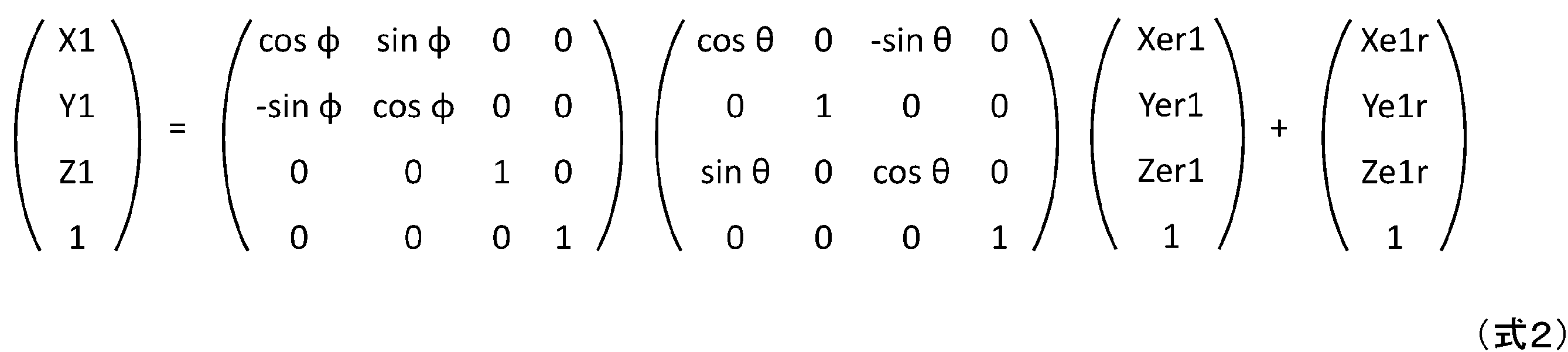
右ディスプレイ202Rの表示映像は、右目P1ERから所定の距離nearの位置にある虚像平面上に見える。虚像平面では、3次元の右目座標系にある巣箱の座標(Xer1、Yer1,Zer1)が次式(3)(4)によって、2次元の右表示座標系の巣箱の座標(Xdr1、Ydr1)に透視投影変換される。


尚、右表示座標系は、虚像平面の表示領域の中央部を原点とし、右方向をXd軸、下方向にYd軸を設定している。虚像平面にある2次元右表示系から、右ディスプレイ202Rを構成する平面表示素子の2次元表示座標系への変換は、右ディスプレイ202R内の光学構成に依存するため、詳細説明を省略する。典型的な例では、虚像平面にある2次元右座標系から、平面表示素子の2次元表示座標系は、虚像平面上の表示サイズを平面表示素子の表示サイズに比例縮小させたものになる。
また、HMDG1に対する右目P1ERの移動量はそれほど大きくないので、右目P1ERは右ディスプレイ202Rに対して相対的に固定して簡易計算することもできる。この場合、右目P1ERの移動量を右ディスプレイ202Rの移動量とみなしてもよい。
以上、右目P1ERに関する座標系の変換を説明してきたが、左目P1ELについても同様な変換が成り立つ。
また、撮像センサ71を原点とする局所座標系である、撮像座標系と世界座標系間の変換も同様な数式で計算できる。さらに、撮像座標系と右目座標系間の変換は、HMDG1の撮像センサ71と右ディスプレイ202R及び左ディスプレイ202Lとの位置関係が決まっているので、世界座標系への変換を介さずに直接変換することもできる。
第1の拡大表示モード&第1の拡大対象モードでは、拡大対象が世界座標で固定されているため、拡大表示領域を拡大対象の見える位置に合わせるため、HMDG1の位置と姿勢情報をもとに、左右目座標系における拡大対象の見える方向を計算する必要がある。
それに対して、第1の拡大表示モード&第2の拡大対象モードでは、拡大対象を撮影映像で追尾するため、撮影座標系上の位置がビデオプロセッサ73及び主制御装置2(映像処理部に相当する)で把握できる。撮影座標系と左右目座標系は世界座標系を介することなく直接座標変換ができる。従って、HMDG1の位置と姿勢情報をリアルタイムで取得することなく、拡大表示領域を拡大対象の見える位置に合わせることができる。
図16Bは、拡大対象とディスプレイにおける拡大表示領域の関係を表す模式図である。
撮像センサ71と右ディスプレイ202R及び左ディスプレイ202Lの高さ方向の位置を合わせ、撮像座標系と右目座標系、左目座標系のY軸(紙面から見て下方向)を共通化して、簡素化した例を示している。配置の関係から、X軸(紙面内で右方向)の原点位置が左右にずれている。撮像の奥行方向や左右目からの奥行方向となるZ軸(紙面の上方向)はほぼ同じだが、原点が左右にずれているため、視差が生じている。
右目PE1Rから鳥BDが見える方向を222R、左目PE1Lから鳥BDが見える方向を222L、撮像センサ71が鳥BDを撮像する方向を221で示している。更に左ディスプレイ202Lと右ディスプレイ202Rが左目PE1Lと右目PE1Rに表示する虚像表示面223を示している。
虚像表示面223と鳥BDが見える方向222Rが交わる位置を中心に、拡大表示領域EDA(R)を設定する。拡大表示領域EDA(R)に、鳥BDの拡大映像BDE(R)が表示される。左目も同様に表示されるが、左ディスプレイ202Lと右ディスプレイ202Rがずれているため、拡大表示領域EDA(L)とEDA(R)は視差を生じる。必要な視差量Δdは、下式(5)により求められる。
Δd=(左右の目の間隔)×(左右の目と虚像表示面223までの距離)/(左右の目と拡大対象である鳥BDまでの距離)・・・(式5)
Δd=(左右の目の間隔)×(左右の目と虚像表示面223までの距離)/(左右の目と拡大対象である鳥BDまでの距離)・・・(式5)
図17は、本実施形態に係る携帯情報端末の右ディスプレイ202R及び右光低減素子212Rの構造を表す模式図である。
同図において、右ディスプレイ202Rは、投射装置2021(有機ELや液晶等)からの投射映像をプリズムで反射させ、ハーフミラー2022の光学的コンバイナに表示映像光2123にて光路を変更してユーザに視認させるものである。また外光2124もハーフミラー2022を介してユーザが視認できるものである、いわゆる一般的なシースルー光学系で構成されるものである。
右光低減素子212Rは、いわゆる光の透過率を画素単位で制御できる、液晶や電子泳動式トナーなどの素子で構成されるものであるが、それに限るものではなく、光の透過率を画素単位で制御できるものであればよい。右光低減素子212Rの画素間には光を透過しないブラックマトリクスが存在する。一方、ハーフミラー2022をフレネルミラーや回折格子で構成する場合、光を透過しないブラックマトリクス領域が生じる。右光低減素子212Rのブラックマトリクスを、ハーフミラー2022のブラックマトリクス領域に構成することにより、光利用効率を上げることができる。ビデオプロセッサ73は、右ディスプレイ202Rの外界の景色に重畳表示する映像信号を生成する。同図においては、例として拡大表示領域EDAに拡大映像を表示する右ディスプレイ用映像信号202RSが生成される。
ビデオプロセッサ73は、拡大表示領域EDAの輝度を落とすための減光信号212RSを生成する。拡大表示領域EDAの外界輝度を下げることで、右ディスプレイに表示される拡大映像を見易くしている。
さらに、ビデオプロセッサ73が、拡大表示領域EDAの輝度を落とすだけでなく、その周囲の輝度をやや落とす減光信号212RSを生成してもよい。
図18は、右ディスプレイ用映像信号202RSで右ディスプレイ202Rの投射装置を駆動し、拡大表示領域EDAの周囲の外界輝度も落とす減光信号212RSで右光低減素子212Rを駆動した結果の右ディスプレイ202Rを表す模式図である。
このように、拡大表示領域EDA以外の輝度が低減され、拡大表示している映像を視認しやすくすることもできる。
さらに表示されたAR表示された拡大表示領域EDAと、減光領域周辺の焦点距離の違いから、減光領域周辺部にぼやけが生じる。このぼやけを目立たせないように、拡大表示領域EDAの周囲の境界線を太線で表示するとよい。境界線はグレー又は中間色で太めとして、拡大表示領域映像とシースルー周辺景色の両立を図る等の処理が有効である。また、重要なAR表示領域は減光領域より小さめとしておくとよい。
また、減光領域周辺部がぼやけることから、右光低減素子212Rの画素数は、右ディスプレイ202Rの画素数より少なく、例えば1/10程度以下でもよい。
以上、上記では説明の簡単化のため右ディスプレイ202Rについての説明をしてきたが、左ディスプレイ202Lについても同様の処理が適用できる。
本実施形態によれば、携帯情報端末を介するユーザの視界内にある対象物を拡大対象物として指定し、その拡大対象物を拡大表示して携帯情報端末に表示することができる。その際、拡大表示された拡大対象物は、ユーザの視界内で拡大する前の対象物の位置に重ねて表示されるので、ユーザの視界内のどの位置に拡大対象物が位置しているかも把握できる。
よって、本実施形態によれば、ユーザが所望する対象の拡大表示と当該オブジェクトの全光景における位置の把握の両立が行える携帯情報端末及び携帯情報端末の表示制御方法を提供することができる。
《第2の実施の形態》
図19は、本実施形態を適用したビデオシースルー型(非透過型)HMDの一例を表す構成図である。図1Aの光学シースルー型HMDと異なる点は、右ディスプレイ202R、左ディスプレイ202Lが透過型ではなく、外界の景色はHMDG1を装着しているユーザP1には見えない点である。HMDG1を装着したままの状態で外界の景色を見る場合は、撮像センサ71で撮像した映像を右ディスプレイ202R、左ディスプレイ202Lに表示するビデオシースルーとし、先に述べたように、やはりジェスチャーで操作したり、図示しない手元のキーボードなどを操作したりすることができる。
図19は、本実施形態を適用したビデオシースルー型(非透過型)HMDの一例を表す構成図である。図1Aの光学シースルー型HMDと異なる点は、右ディスプレイ202R、左ディスプレイ202Lが透過型ではなく、外界の景色はHMDG1を装着しているユーザP1には見えない点である。HMDG1を装着したままの状態で外界の景色を見る場合は、撮像センサ71で撮像した映像を右ディスプレイ202R、左ディスプレイ202Lに表示するビデオシースルーとし、先に述べたように、やはりジェスチャーで操作したり、図示しない手元のキーボードなどを操作したりすることができる。
またハードウェア構成は、図2で示した構成のうち、右光低減素子212R、左光低減素子212Lは不要となるがそのほかは光学シースルー型HMDと同等であるので、図示は省略する。
また、本ビデオシースルー型HMDの場合は、右ディスプレイ202R及び左ディスプレイ202Lには図10Aに示した撮影映像CIMが表示され、拡大表示領域EDAはビデオプロセッサ73にて撮影映像CIMに重畳処理されて表示される。先に述べた光学シースルー型のHMD(光学シースルー式)の場合は、透過された景色の輝度を重畳表示された拡大表示領域EDAに対して落とすために右光低減素子212R、左光低減素子212Lを用いたが、ビデオシースルー型のHMDでは撮影映像CIMの輝度を映像信号処理で落とす処理を行った後、拡大表示領域EDAを重畳すればよい。その他の処理は光学シースルー型HMDと同様である。
本実施形態によればビデオシースルー型(非透過型)HMDでも第1実施形態と同様、ユーザが所望する対象の拡大表示と当該オブジェクトの全光景における位置の把握の両立が行える携帯情報端末及び携帯情報端末の表示制御方法を提供することができる。
《第3の実施の形態》
図20A~図20Eは、タブレット型の携帯情報端末に本実施形態を適用した例を表す模式図である。
図20A~図20Eは、タブレット型の携帯情報端末に本実施形態を適用した例を表す模式図である。
本実施形態に係る携帯情報端末が図2Aの光学シースルー型HMDと異なる点は、図2Aの光学シースルー型HMDが右ディスプレイ202R、左ディスプレイ202Lの2つのディスプレイを有するのに対し、本実施形態に係る携帯情報端末は液晶や有機ELで構成された一つのディスプレイ202のみを備え、外界の景色はビデオシースルー型HMDと同様に撮像センサ71で撮像した撮影映像CIMをディスプレイ202に表示している点、さらにディスプレイ202はタッチパネルが積層される構成である点である。
またハードウェア構成は、図2で示した構成のうち、右光低減素子212R、左光低減素子212L、右視線検出器1001R及び左視線検出器1001Lが無い以外は、光学シースルー型HMDと同等であるので、図示は省略する。
本実施形態に係る携帯情報端末の一例としてのタブレット型端末においては、画面に触れて操作を行えるタッチパネルを備えるので、HMDでの本実施形態の適用例とは異なり、タッチ操作で拡大対象の指定や拡大表示領域の大きさ、拡大率の指定を行う。
図20Aにおいて、HNDは、HMDG1を装着したユーザの手を表している。
<拡大表示モードへの切換え>
まず図20Aに示したように、ユーザの拡大表示を行いたい旨の指示として、手HNDでディスプレイ202をタップする。該タップ動作をビデオプロセッサ73及び主制御装置2が検知し、主制御装置2は拡大表示の指示が与えられたと判定し、図20Bに示すように所定の位置(例えばディスプレイ202の中央)に拡大表示領域EDAを表示するように制御を切換える。
まず図20Aに示したように、ユーザの拡大表示を行いたい旨の指示として、手HNDでディスプレイ202をタップする。該タップ動作をビデオプロセッサ73及び主制御装置2が検知し、主制御装置2は拡大表示の指示が与えられたと判定し、図20Bに示すように所定の位置(例えばディスプレイ202の中央)に拡大表示領域EDAを表示するように制御を切換える。
図20Bは、上記拡大表示指示を受付けた後のディスプレイ202の状態を表す模式図である。
同図は、拡大表示領域EDAには、撮影映像CIMの映像のうち該拡大表示領域EDA中央の位置に相当する映像が、初期値で指定されている拡大率、初期値で指定されている拡大表示領域EDAの大きさ(面積)で表示された状態を示している。拡大表示領域EDAは円形である例を示したが、方形などでもよく、特に制限はない。
<拡大表示領域の表示位置指定>
図20Cは、ユーザが拡大表示領域EDAの表示位置を指定する操作を表す模式図である。
図20Cは、ユーザが拡大表示領域EDAの表示位置を指定する操作を表す模式図である。
ユーザは、表示されている拡大表示領域EDAを、ドラッグして表示対象である拡大映像BHEが拡大表示領域EDAの中央付近に来るように指定する。
そしてユーザはドラッグした手HNDをディスプレイ202から離す事で、拡大表示領域EDAに表示されている略中央の映像を拡大対象と拡大表示領域EDAの表示位置の指定が確定する。
続いてユーザは、拡大表示領域EDAの大きさ(円の大きさ)と表示対象の拡大率を指定する。
<拡大表示領域の大きさと拡大率の指定>
図20Dは、ユーザが拡大表示領域EDAの大きさと上記拡大対象物の表示時の拡大率を指定する操作を表す模式図である。
図20Dは、ユーザが拡大表示領域EDAの大きさと上記拡大対象物の表示時の拡大率を指定する操作を表す模式図である。
ユーザは、拡大表示領域EDAの周囲枠に2本の指(本例では親指と人差し指)を当てるピンチアウト操作で拡大表示領域EDAの大きさを調整し、さらに拡大表示領域EDAの内側をピンチアウト操作する事で、拡大映像BHEの拡大率を可変して所望の指定を行う。
図20Eは、表示モードを指定するためのディスプレイ202の表示を表す模式図である。
図20Dの操作終了後、各表示モードと各拡大対象モードを選択するためのメニューMENUが表示される。ユーザは、このメニューMENUから所望の表示モード及び拡大対象モードをタップ操作で選択することによって、表示モードを指定する。
尚、第1の表示モードにおいて、第1の拡大対象モードを実装せず、第2の拡大対象モードのみとしてもよい。この場合、第1の表示モードと第2の表示モードだけでもよい。
このようなユーザインターフェースにすれば、タッチパネルであるタブレット端末やスマートフォン等の携帯情報端末ではタッチパネルによる表示モードの各種パラメータを指定できて便利である。
タブレット型やスマートフォン型の携帯情報端末は、HMDに比べて、ディスプレイの動きとユーザの目の位置関係が独立している。従って、第1の拡大表示モード&第2の拡大対象モードにおいて、HMDでは座標変換の複雑な計算が必要であったが、ディスプレイの上下左右の空間的な動き量だけ、拡大表示領域を逆に移動させる簡易動作でも実現しやすい。
本実施形態によればタブレット端末やスマートフォンのように一つのディスプレイ202を有する携帯情報端末でも第1実施形態と同様、ユーザが所望する対象の拡大表示と当該オブジェクトの全光景における位置の把握の両立が行える携帯情報端末及び携帯情報端末の表示制御方法を提供することができる。
《第4の実施の形態》
図21は、本実施形態に係る携帯情報端末をARサービスに応用した場合のシステム構成を表す模式図である。
図21は、本実施形態に係る携帯情報端末をARサービスに応用した場合のシステム構成を表す模式図である。
同図において、ARシステム400は、本実施形態に係る携帯情報端末であるHMDG1~G5が、移動体無線通信網の基地局B1及びネットワークN1を介して管理サーバS1に接続している。HMDG1~G5は、図示しない異なるユーザP1~P5が装着しているものである。
管理サーバS1は、本実施形態に係るARサービスを管理する管理サーバである。
サービスエリアA1は、本ARサービスが提供される範囲を示す。例えば特定の観光地における所定の範囲で本ARサービスが提供されるサービスエリアを表す。
管理サーバS1は、ネットワークN1を介して取得した、複数の情報を管理する。管理サーバS1が管理する情報は、例えば、各HMDG1~HMDG5のユーザに関するアカウント情報、基地局B1を介して取得したHMDG1の位置情報や注視点情報、本ARサービスで、各ユーザがアップロードした映像情報やコメント情報などである。
各ユーザに関する情報には、氏名を含むニックネームやハンドルネームなどのユーザ情報(ユーザ識別情報)や、ユーザ属性情報(年齢、趣味、嗜好等)などがある。
登録方法は、本ARシステムサービスを受けるためのHMDG1で使用されるアプリケーションプログラム上で、プロフィールとして入力してもよいし、ユーザの使用した他のアプリケーションプログラムや行動履歴から自動収集、自動生成してもよいし、他のアプリケーションプログラムで登録した情報と連携してもよい。
なお、ユーザ属性情報の記憶場所としては、HMDでも管理サーバS1でもよい。
本実施形態は、説明を解り易くするため、本実施形態では、図21に示すように、5人のユーザが装着するHMDG1~HMDG5の例を示しているが、ユーザ数に制限はない。
また、図21において、HMDG1~HMDG5は基地局B1を介して本ARサービスに接続している例を示しているが、HMDG1~HMDG5は図示しない無線ルータを経由してネットワークN1に接続される構成としてもよい。
各HMDG1~HMDG5のハードウェア構成は、図2に示したものと同様である。
図22は、本ARシステムのサービスが使用される環境を表す模式図である。
同図では、雲CL、飛行中の飛行機AP、飛行中の飛行船AS、飛行中の鳥BDF、飛行船AS付近の領域AS1、飛行機AP付近の領域AP1を表している。また、ユーザP1はHMDG1を、ユーザP2はHMDG2を、ユーザP3はHMDG3を装着している。また、各ユーザP1~P3はサービスエリアA1にいることを表している。
さらにユーザP1は飛行中の鳥BDFを注視しており、ユーザP2及びユーザP3はAS1の範囲内を注視している状態を表している。
ここで、ユーザP2の注視している飛行船ASの世界座標(Xas、Yas、Zas)は、ARシステムを通じてユーザP1に通知されることとする。
図23は、他ユーザP2の注視している飛行船ASの拡大映像ASEを、拡大表示領域EDAに表す模式図である。
このように、複数のユーザが共有している景色の中で、他のユーザが注視している物体を拡大表示されるので、他のユーザが注視している物体も見逃すことなく、注視しているという状況を共有することができる。また、ユーザP1が注視している物体(例えば飛行中の鳥BDF)も他のユーザへその世界座標をARシステム経由で送信して、注視しているという状況と物体を共有することができる。
図24は、HMDと管理サーバの処理手順を表すフローチャートである。
S2401:ユーザP1の観光地におけるARシステムへのログイン処理として、HMDG1の主制御装置2は、管理サーバS1へ、ユーザID、パスワード、HMDG1の座標、サービス課金に支払い済みの情報、などの認証情報を送信する。
S2402:管理サーバS1側で受信したHMDG1の位置(座標)がARシステム400のサービスエリアA1内か否か、ユーザID、パスワードがあらかじめ登録された情報と一致したか否かの認証結果を送信する。
S2403:HMDG1の主制御装置2は、受信した認証結果がサービスエリアA1内であり、ユーザID、パスワードが登録情報と一致であれば認証OKとし、次の処理へと進める。それ以外の場合は処理を終了する。
これらの処理は、他ユーザが装着したHMDG2、HMDG3も同様であり、管理サーバS1の処理も同様である。
S2404:HMDG1の主制御装置2は、ユーザP1の注視点(世界座標)を検出する。
S2405:HMDG1の主制御装置2は、さらにS2405で検出した注視点を、HMDG1の位置と共に管理サーバS1へ送信する。
S2406:管理サーバS1側では、各ユーザが装着しているHMDG1、HMDG2から受信した注視点情報を各HMDへブロードキャストする。
S2407:HMDG1の主制御装置2は、受信したユーザP2の注視点が右ディスプレイ202Rの視野にあるか、表示判定する。
S2408:そしてS2407で表示すべき注視点があると判定した場合、HMDG1の主制御装置2は、注視点の映像を拡大表示領域EDA上に拡大表示する処理を行う。
拡大表示開始後に、拡大表示モードや拡大対象モード、拡大表示位置の変更、拡大表示領域サイズ変更、拡大率変更などは第1の実施の形態と同様であり、詳細説明を省略する。
図25は、本ARシステムのサービスが使用される環境を表す模式図である。
同図は、観光地の中の遺跡HR、遺跡HRの一部である壺R1、遺跡HRの一部である像R2、遺跡HRの一部である上部構造物R3、及び本ARシステムが提供されるサービスエリアA2を表す。
このサービスエリアA2において、ARシステムのサービスを提供する観光事業者が重要な遺跡の世界座標(例えば壺R1)を管理サーバS1へ登録されているものとする。
またHMDG1を装着したユーザP1は、サービスエリアA2を訪れ、遺跡HRの一部を見ているものとする。
図26は、本ARシステムのサービスにおけるHMDの表示例を表す模式図である。
ユーザP1の装着したHMDG1の右ディスプレイ202Rには、観光事業者が管理サーバS1に登録した壺R1(図25参照)の拡大映像R1Eが拡大表示領域EDA上に表示される。
このようにすれば、ユーザP1は、重要な遺跡である壺R1を、見逃すことなく、また拡大表示されるので視認性よく観ることができる。
図27は、図26に示したHMDと管理サーバの処理手順を表すフローチャートである。
同図において、処理S2401、S2402、S2403、S2407、S2408は図24に示した処理と同様である。
管理サーバS1においては、観光事業者から重要な遺跡の世界座標が登録される。
S2601:管理サーバS1は、観光事業者から登録のあった遺跡の世界座標をブロードキャストする。
上記の処理を行うことで、図26に示したHMDG1の右ディスプレイ202Rへの表示が可能となる。
拡大表示開始後に、拡大表示モードや拡大対象モードの変更、拡大表示位置の変更、拡大表示領域サイズ変更、拡大率変更などは第1の実施の形態と同様であり、詳細説明を省略する。
本実施形態によれば、他人が注視している注視点を自分が使用する携帯情報端末において拡大表示することができる。その際、第1実施形態と同様、ユーザが所望する対象としての他人に注視点の拡大表示と当該注視点のユーザの視野における位置の把握の両立が行える携帯情報端末及び携帯情報端末の表示制御方法を提供することができる。
以上、本発明は上記した実施形態に限定されるものではなく、様々な変形例が含まれる。上記した実施形態は本発明を分かりやすく説明するために詳細に説明したものであり、必ずしも説明した全ての構成を備えるものに限定されるものではない。また、ある実施形態の構成の一部を他の実施形態の構成に置き換えることが可能である。
また、ある実施形態の構成に他の実施形態の構成を加えることも可能である。また、各実施形態の構成の一部について、他の構成の追加・削除・置換をすることが可能である。
また、上記の各構成は、それらの一部又は全部が、ハードウェアで構成されても、プロセッサでプログラムが実行されることにより実現されるように構成されてもよい。また、制御線や情報線は説明上必要と考えられるものを示しており、製品上必ずしも全ての制御線や情報線を示しているとは限らない。実際には殆ど全ての構成が相互に接続されていると考えてもよい。
2 :主制御装置
3 :システムバス
4 :記憶装置
5 :センサ装置
6 :通信処理装置
7 :映像処理装置
8 :音声処理装置
9 :操作入力装置
10 :視線検出装置
15 :旧図
41 :プログラム記憶領域
42 :データ記憶領域
43 :ワークエリア
51 :測位センサ
52 :地磁気センサ
53 :測距センサ
54 :加速度センサ
55 :ジャイロセンサ
61 :LAN通信機
62 :移動体無線通信機
63 :近接無線通信機
71 :撮像センサ
73 :ビデオプロセッサ
81 :音声入出力部
82 :音声認識部
83 :音声デコーダ
84 :音声イコライザー
202 :ディスプレイ
202L :左ディスプレイ
202R :右ディスプレイ
202RS :右ディスプレイ用映像信号
212L :左光低減素子
212R :右光低減素子
212RS :減光信号
222R :方向
223 :虚像表示面
400 :ARシステム
1001L :左視線検出器
1001R :右視線検出器
2021 :投射装置
2022 :ハーフミラー
2123 :表示映像光
2124 :外光
A1 :サービスエリア
A2 :サービスエリア
AP :飛行機
AP1 :領域
AR :本
AS :飛行船
AS1 :領域
ASE :拡大映像
B1 :基地局
BD :鳥
BDE :拡大映像
BDF :鳥
BH :巣箱
BHE :拡大映像
BR :枝
BRE :拡大映像
CIM :撮影映像
CL :雲
EDA :拡大表示領域
EIM1 :拡大対象の映像
EIMA :拡大対象の映像
EIMi :拡大対象の初期映像
EIMrt :映像
G1~G5 :HMD
G10 :筐体
HND :手
HR :遺跡
MENU :メニュー
N1 :ネットワーク
P1~P5 :ユーザ
P1EL :左目
P1ER :右目
PE1L :左目
PE1R :右目
R1 :壺
R1E :拡大映像
R2 :像
R3 :上部構造物
S1 :管理サーバ
TR :樹木
3 :システムバス
4 :記憶装置
5 :センサ装置
6 :通信処理装置
7 :映像処理装置
8 :音声処理装置
9 :操作入力装置
10 :視線検出装置
15 :旧図
41 :プログラム記憶領域
42 :データ記憶領域
43 :ワークエリア
51 :測位センサ
52 :地磁気センサ
53 :測距センサ
54 :加速度センサ
55 :ジャイロセンサ
61 :LAN通信機
62 :移動体無線通信機
63 :近接無線通信機
71 :撮像センサ
73 :ビデオプロセッサ
81 :音声入出力部
82 :音声認識部
83 :音声デコーダ
84 :音声イコライザー
202 :ディスプレイ
202L :左ディスプレイ
202R :右ディスプレイ
202RS :右ディスプレイ用映像信号
212L :左光低減素子
212R :右光低減素子
212RS :減光信号
222R :方向
223 :虚像表示面
400 :ARシステム
1001L :左視線検出器
1001R :右視線検出器
2021 :投射装置
2022 :ハーフミラー
2123 :表示映像光
2124 :外光
A1 :サービスエリア
A2 :サービスエリア
AP :飛行機
AP1 :領域
AR :本
AS :飛行船
AS1 :領域
ASE :拡大映像
B1 :基地局
BD :鳥
BDE :拡大映像
BDF :鳥
BH :巣箱
BHE :拡大映像
BR :枝
BRE :拡大映像
CIM :撮影映像
CL :雲
EDA :拡大表示領域
EIM1 :拡大対象の映像
EIMA :拡大対象の映像
EIMi :拡大対象の初期映像
EIMrt :映像
G1~G5 :HMD
G10 :筐体
HND :手
HR :遺跡
MENU :メニュー
N1 :ネットワーク
P1~P5 :ユーザ
P1EL :左目
P1ER :右目
PE1L :左目
PE1R :右目
R1 :壺
R1E :拡大映像
R2 :像
R3 :上部構造物
S1 :管理サーバ
TR :樹木
Claims (10)
- ユーザが携帯する携帯情報端末であって、
撮像センサと、
前記撮像センサの出力を映像処理するプロセッサと、
前記プロセッサの出力を表示するディスプレイと、
を具備し、
前記プロセッサは、
前記撮像センサで撮影された映像の拡大対象の指定及び前記拡大対象を前記ディスプレイに拡大表示する拡大表示領域の指定を受け付け、
拡大表示させない時に前記拡大対象を視認する方向に、前記拡大対象を所定の倍率で拡大し、前記拡大表示する領域に割り当てるように前記ディスプレイを制御する
携帯情報端末。 - 請求項1記載の携帯情報端末であって、
前記ディスプレイの実空間における動きを出力する動きセンサを備え、
前記プロセッサは、
当初指定した拡大対象を視認する方向に対して、前記ディスプレイの実空間における動きから、ディスプレイの動きを相殺するように新たに前記ディスプレイの表示面内における拡大対象の移動後の位置を算出し、拡大表示領域のほぼ中心とする第1の表示制御を行う、
携帯情報端末。 - 請求項1記載の携帯情報端末であって、
前記撮像センサは前記ディスプレイと所定の位置関係にあり、
前記プロセッサは、
前記撮像センサが取得した撮影映像上で当初指定した拡大対象と、継続して取得した撮影映像上で映像特徴の相関の高い領域を抽出し、
前記当初指定した拡大対象位置から前記相関の高い領域までの差を拡大対象の動きとして検出し、
前記拡大対象の動きに追随して前記撮影映像上の拡大対象位置を移動させ、
撮影映像上の拡大対象位置と前記撮像センサと前記ディスプレイの前記所定の位置関係から拡大対象視認方向を算出し、
前記ディスプレイで表示する拡大表示領域のほぼ中心とする第2の表示制御を行う、
携帯情報端末。 - 請求項2記載の携帯情報端末であって、
前記プロセッサは、第2の表示制御として、
前記撮像センサが取得した撮影映像上で当初指定した拡大対象と、継続して取得した撮影映像上で映像特徴の相関の高い領域を抽出し、
前記当初指定した拡大対象位置から前記相関の高い領域までの差を拡大対象の動きとして検出し、
前記拡大対象の動きに追随して前記撮影映像上の拡大対象位置を移動させ、
撮影映像上の拡大対象位置と前記撮像センサと前記ディスプレイの前記所定の位置関係から拡大対象視認方向を算出し、
前記ディスプレイで表示する拡大表示領域のほぼ中心とする表示制御を行い、
前記第1の表示制御と前記第2の表示制御を切替できる、
携帯情報端末。 - 請求項1記載の携帯情報端末であって、
前記プロセッサは、
前記撮像センサが取得した撮影映像上で当初指定した拡大対象を、前記拡大対象として、前記撮像センサが撮像した拡大対象の映像を拡大表示する第1の拡大表示モードと、
前記ディスプレイが拡大表示する拡大表示領域の視認方向にあるものを、前記拡大対象として、前記撮像センサが撮像した拡大対象の映像を拡大表示する第2の拡大表示モードを持つ、
携帯情報端末。 - 請求項4に記載の携帯情報端末であって、
前記プロセッサは、前記第1の表示制御と前記第2の表示制御との切替選択、前記拡大対象の指定、及び拡大倍率の指定をジェスチャー動作により受け付ける、
携帯情報端末。 - 請求項1記載の携帯情報端末であって、
通信装置をさらに備え、
前記プロセッサは、前記通信装置から前記拡大対象に関する情報を受信して前記拡大対象を指定する
携帯情報端末。 - 請求項1記載の携帯情報端末であって、
前記プロセッサは、前記拡大表示領域が前記ディスプレイの周辺部に達すると拡大表示を中止する
携帯情報端末。 - 請求項1記載の携帯情報端末であって、
メモリを更に備え、
前記プロセッサは、拡大表示中止時の拡大表示状態を前記メモリに記憶し、
拡大表示を中止後に、メニュー操作又は所定のジェスチャー動作を受け付けると、拡大表示中止前の前記拡大表示状態に戻す、
携帯情報端末。 - 携帯情報端末の表示制御方法であって、
空間を撮影する撮像ステップと、
前記撮像ステップで撮影された映像を処理する映像処理ステップと、
前記映像処理ステップで撮影された映像を表示する映像表示ステップと、
前記撮像ステップで撮影された映像の拡大対象を指定する拡大対象指定ステップと、
前記拡大対象を前記映像表示ステップにて拡大表示する拡大表示領域を指定する拡大表示領域指定ステップと、
システム制御ステップと、
から成り、
前記システム制御ステップは、拡大表示させない時に拡大対象を視認する方向に、前記拡大対象を所定の倍率で拡大し、前記拡大表示する領域に割り当てるように映像処理ステップを制御する第1の拡大表示モードを持つ、
携帯情報端末の表示制御方法。
Priority Applications (1)
| Application Number | Priority Date | Filing Date | Title |
|---|---|---|---|
| PCT/JP2023/003805 WO2024166171A1 (ja) | 2023-02-06 | 2023-02-06 | 携帯情報端末及び携帯情報端末の表示制御方法 |
Applications Claiming Priority (1)
| Application Number | Priority Date | Filing Date | Title |
|---|---|---|---|
| PCT/JP2023/003805 WO2024166171A1 (ja) | 2023-02-06 | 2023-02-06 | 携帯情報端末及び携帯情報端末の表示制御方法 |
Publications (1)
| Publication Number | Publication Date |
|---|---|
| WO2024166171A1 true WO2024166171A1 (ja) | 2024-08-15 |
Family
ID=92262094
Family Applications (1)
| Application Number | Title | Priority Date | Filing Date |
|---|---|---|---|
| PCT/JP2023/003805 Ceased WO2024166171A1 (ja) | 2023-02-06 | 2023-02-06 | 携帯情報端末及び携帯情報端末の表示制御方法 |
Country Status (1)
| Country | Link |
|---|---|
| WO (1) | WO2024166171A1 (ja) |
Citations (3)
| Publication number | Priority date | Publication date | Assignee | Title |
|---|---|---|---|---|
| JP2014183380A (ja) * | 2013-03-18 | 2014-09-29 | Nintendo Co Ltd | 情報処理プログラム、情報処理装置、情報処理システム、パノラマ動画表示方法、および、制御データのデータ構造 |
| JP2016161734A (ja) * | 2015-03-02 | 2016-09-05 | セイコーエプソン株式会社 | 表示装置、表示装置の制御方法、および、プログラム |
| JP2016194763A (ja) * | 2015-03-31 | 2016-11-17 | 富士通株式会社 | 画像処理装置、画像処理プログラム、及び画像処理方法 |
-
2023
- 2023-02-06 WO PCT/JP2023/003805 patent/WO2024166171A1/ja not_active Ceased
Patent Citations (3)
| Publication number | Priority date | Publication date | Assignee | Title |
|---|---|---|---|---|
| JP2014183380A (ja) * | 2013-03-18 | 2014-09-29 | Nintendo Co Ltd | 情報処理プログラム、情報処理装置、情報処理システム、パノラマ動画表示方法、および、制御データのデータ構造 |
| JP2016161734A (ja) * | 2015-03-02 | 2016-09-05 | セイコーエプソン株式会社 | 表示装置、表示装置の制御方法、および、プログラム |
| JP2016194763A (ja) * | 2015-03-31 | 2016-11-17 | 富士通株式会社 | 画像処理装置、画像処理プログラム、及び画像処理方法 |
Non-Patent Citations (1)
| Title |
|---|
| YAMAMOTO SAYAKA: "Magnifying glass with holoLens camera enlarges objects for better viewing", MOGU LIVE, 1 March 2017 (2017-03-01), XP093198840, Retrieved from the Internet <URL:https://www.moguravr.com/hololens-camera/> * |
Similar Documents
| Publication | Publication Date | Title |
|---|---|---|
| US12182322B2 (en) | Visibility improvement method based on eye tracking, machine-readable storage medium and electronic device | |
| KR102497683B1 (ko) | 다수의 가상 캐릭터를 제어하는 방법, 기기, 장치 및 저장 매체 | |
| JP6780642B2 (ja) | 情報処理装置、情報処理方法及びプログラム | |
| US11024083B2 (en) | Server, user terminal device, and control method therefor | |
| KR20190008610A (ko) | 이동 단말기 및 그 제어 방법 | |
| JP2016144089A (ja) | 画像処理装置およびその制御方法 | |
| US20170147180A1 (en) | Mobile terminal and method for controlling the same | |
| WO2018150831A1 (ja) | 情報処理装置、情報処理方法及び記録媒体 | |
| CN112292657B (zh) | 围绕布景进行移动 | |
| WO2022123750A1 (ja) | 表示装置および表示方法 | |
| CN116048281A (zh) | 一种虚拟现实场景中的交互方法、装置、设备及存储介质 | |
| CN111612916A (zh) | 在环境内的移动 | |
| CN116997886A (zh) | 扩展现实中的数字助理交互 | |
| CN112381729B (zh) | 图像处理方法、装置、终端及存储介质 | |
| KR102140077B1 (ko) | 서버, 사용자 단말 장치 및 그 제어 방법 | |
| EP4509962A1 (en) | Method, apparatus, electronic device, and storage for medium extended reality-based interaction control | |
| JP7724341B2 (ja) | ウェアラブル端末装置、プログラムおよび画像処理方法 | |
| JP2024504159A (ja) | 撮影方法、装置、電子機器及び可読記憶媒体 | |
| JP7400810B2 (ja) | 情報処理装置、情報処理方法、及び記録媒体 | |
| JP2019022014A (ja) | 画像提供方法、画像提供装置及びコンピュータプログラム | |
| WO2024116270A1 (ja) | 携帯情報端末及び仮想現実表示システム | |
| HK40028495A (en) | Display method and device of virtual picture scroll, apparatus and storage medium | |
| WO2025263024A1 (ja) | 情報処理システム及び情報処理方法 |
Legal Events
| Date | Code | Title | Description |
|---|---|---|---|
| 121 | Ep: the epo has been informed by wipo that ep was designated in this application |
Ref document number: 23921008 Country of ref document: EP Kind code of ref document: A1 |
|
| NENP | Non-entry into the national phase |
Ref country code: DE |
|
| 122 | Ep: pct application non-entry in european phase |
Ref document number: 23921008 Country of ref document: EP Kind code of ref document: A1 |
|
| NENP | Non-entry into the national phase |
Ref country code: JP |