WO2022123750A1 - 表示装置および表示方法 - Google Patents
表示装置および表示方法 Download PDFInfo
- Publication number
- WO2022123750A1 WO2022123750A1 PCT/JP2020/046148 JP2020046148W WO2022123750A1 WO 2022123750 A1 WO2022123750 A1 WO 2022123750A1 JP 2020046148 W JP2020046148 W JP 2020046148W WO 2022123750 A1 WO2022123750 A1 WO 2022123750A1
- Authority
- WO
- WIPO (PCT)
- Prior art keywords
- user
- target
- display
- display device
- obstruction
- Prior art date
Links
- 238000000034 method Methods 0.000 title claims description 78
- 230000000007 visual effect Effects 0.000 claims abstract description 76
- 230000008859 change Effects 0.000 claims description 89
- 238000004891 communication Methods 0.000 claims description 31
- 230000009467 reduction Effects 0.000 claims description 5
- 101100347655 Saccharomyces cerevisiae (strain ATCC 204508 / S288c) NAB3 gene Proteins 0.000 description 125
- 238000012545 processing Methods 0.000 description 58
- 230000008569 process Effects 0.000 description 28
- 238000001514 detection method Methods 0.000 description 22
- 230000006870 function Effects 0.000 description 20
- 230000010365 information processing Effects 0.000 description 13
- 230000003287 optical effect Effects 0.000 description 10
- 238000012790 confirmation Methods 0.000 description 8
- 230000004048 modification Effects 0.000 description 8
- 238000012986 modification Methods 0.000 description 8
- 230000000694 effects Effects 0.000 description 7
- 210000003128 head Anatomy 0.000 description 5
- 239000000126 substance Substances 0.000 description 5
- 238000010586 diagram Methods 0.000 description 4
- 230000014509 gene expression Effects 0.000 description 3
- 238000007726 management method Methods 0.000 description 3
- 230000000903 blocking effect Effects 0.000 description 2
- 208000013057 hereditary mucoepithelial dysplasia Diseases 0.000 description 2
- 239000004973 liquid crystal related substance Substances 0.000 description 2
- 238000010295 mobile communication Methods 0.000 description 2
- 238000003825 pressing Methods 0.000 description 2
- 230000011514 reflex Effects 0.000 description 2
- 230000004044 response Effects 0.000 description 2
- 238000002834 transmittance Methods 0.000 description 2
- 206010052143 Ocular discomfort Diseases 0.000 description 1
- 230000003190 augmentative effect Effects 0.000 description 1
- 230000005540 biological transmission Effects 0.000 description 1
- 210000004087 cornea Anatomy 0.000 description 1
- 238000007781 pre-processing Methods 0.000 description 1
- 238000012913 prioritisation Methods 0.000 description 1
- 210000001747 pupil Anatomy 0.000 description 1
- 230000004461 rapid eye movement Effects 0.000 description 1
- 230000000717 retained effect Effects 0.000 description 1
- 238000010079 rubber tapping Methods 0.000 description 1
- 238000010187 selection method Methods 0.000 description 1
- 239000004065 semiconductor Substances 0.000 description 1
- 230000001052 transient effect Effects 0.000 description 1
- 230000001960 triggered effect Effects 0.000 description 1
Images


Classifications
-
- G—PHYSICS
- G06—COMPUTING; CALCULATING OR COUNTING
- G06V—IMAGE OR VIDEO RECOGNITION OR UNDERSTANDING
- G06V10/00—Arrangements for image or video recognition or understanding
- G06V10/20—Image preprocessing
- G06V10/26—Segmentation of patterns in the image field; Cutting or merging of image elements to establish the pattern region, e.g. clustering-based techniques; Detection of occlusion
- G06V10/273—Segmentation of patterns in the image field; Cutting or merging of image elements to establish the pattern region, e.g. clustering-based techniques; Detection of occlusion removing elements interfering with the pattern to be recognised
-
- G—PHYSICS
- G06—COMPUTING; CALCULATING OR COUNTING
- G06F—ELECTRIC DIGITAL DATA PROCESSING
- G06F3/00—Input arrangements for transferring data to be processed into a form capable of being handled by the computer; Output arrangements for transferring data from processing unit to output unit, e.g. interface arrangements
- G06F3/01—Input arrangements or combined input and output arrangements for interaction between user and computer
- G06F3/011—Arrangements for interaction with the human body, e.g. for user immersion in virtual reality
- G06F3/013—Eye tracking input arrangements
-
- G—PHYSICS
- G06—COMPUTING; CALCULATING OR COUNTING
- G06F—ELECTRIC DIGITAL DATA PROCESSING
- G06F3/00—Input arrangements for transferring data to be processed into a form capable of being handled by the computer; Output arrangements for transferring data from processing unit to output unit, e.g. interface arrangements
- G06F3/01—Input arrangements or combined input and output arrangements for interaction between user and computer
- G06F3/048—Interaction techniques based on graphical user interfaces [GUI]
- G06F3/0481—Interaction techniques based on graphical user interfaces [GUI] based on specific properties of the displayed interaction object or a metaphor-based environment, e.g. interaction with desktop elements like windows or icons, or assisted by a cursor's changing behaviour or appearance
- G06F3/04815—Interaction with a metaphor-based environment or interaction object displayed as three-dimensional, e.g. changing the user viewpoint with respect to the environment or object
-
- G—PHYSICS
- G06—COMPUTING; CALCULATING OR COUNTING
- G06T—IMAGE DATA PROCESSING OR GENERATION, IN GENERAL
- G06T19/00—Manipulating 3D models or images for computer graphics
- G06T19/006—Mixed reality
Definitions
- the present invention relates to a technique for displaying a display device or an information processing device, and relates to a technique for displaying an image such as a virtual object.
- HMD head-mounted information processing device
- the head-mounted information processing device displays real-world objects and virtual objects, and fuses the real world and the virtual world in real time and seamlessly, as if a virtual object exists in the real world. You can have an experience.
- a display method there are a so-called video see-through type and an optical see-through type.
- video see-through type images corresponding to real objects and virtual objects are generated and displayed on the display unit on the front of the head.
- optical see-through type the actual object in front of the eyes is visible, and the image of the virtual object is displayed on the display unit by superimposing it on it.
- Patent Document 1 describes that "information is appropriately displayed while ensuring the user's field of view" and the following.
- An information display system having a transmissive head-mounted display the control unit detects the user's gaze point based on the image data of both eyes of the user, and the user virtual screens based on the gaze point. It is determined whether the user is gazing at the top or the background behind the virtual screen, and it is determined whether the user's line-of-sight area overlaps with the display position of the object on the virtual screen, and the gazing point moves. If so, the display position and / or display form of the object is changed based on the determination result.
- a display device such as a conventional head-mounted information processing device
- the entity that the user wants to see may be displayed depending on the arrangement relationship and the user's line-of-sight position.
- the virtual object may be obscured by other entities or virtual objects, making it difficult to see or hindering the visibility.
- Patent Document 1 in an HMD that realistically sees through an actual object and displays a virtual object on a virtual screen, whether the user is gazing on the virtual screen based on the user's gaze point or not, paying close attention to the background. It is described that it is determined whether or not the object is present, and whether or not the line of sight overlaps the object on the virtual screen, and the display position and / or display form of the virtual object is changed according to the determination results of both. There is. Patent Document 1 describes that when the object that the user is gazing at is overlapped and covered with a virtual object, the information display system changes the display form according to the display position or transparency of the virtual object and displays the object. ing.
- Patent Document 1 it is considered to eliminate the visual obstruction on the line of sight, but it is only that, and no consideration is given to the obstruction to the range desired to be visually recognized by the user. Further, Patent Document 1 does not suggest any display reflecting the shielding relationship when the real object and the virtual object are arranged in three dimensions (Three-Dimensional: 3D).
- An object of the present invention is the technique of a display device such as a head-mounted information processing device capable of displaying a virtual object arranged in three dimensions, by using another object with respect to the visible range of an object such as a real object or a virtual object that the user wants to see.
- a typical embodiment of the present invention has the following configuration.
- the display device of the embodiment includes a display device for displaying an image and a processor for controlling the display of the image, and the display device includes an individual object object cut out from an object in the outside world and a three-dimensional object as an object.
- the display device includes an individual object object cut out from an object in the outside world and a three-dimensional object as an object.
- the display device includes an individual object object cut out from an object in the outside world and a three-dimensional object as an object.
- the display device includes an individual object object cut out from an object in the outside world and a three-dimensional object as an object.
- the display device includes an individual object object cut out from an object in the outside world and a three-dimensional object as an object.
- the display device includes an individual object object cut out from an object in the outside world and a three-dimensional object as an object.
- the display device includes an individual object object cut out from an object in the outside world and a three-dimensional object as an object.
- an object such as a real object or a virtual object that the user wants to see can be used.
- the visual obstruction can be eliminated or reduced, and the user can appropriately see the entire object, and such a function can be troubled by the user. It can be realized with less usability.
- the configuration outline and the display example of the head-mounted information processing apparatus (HMD) which is the display apparatus of Embodiment 1 of this invention are shown.
- the classification of objects, the obstruction obstruction relationship, and the categories are shown.
- a display example in the case of transparency adjustment is shown.
- a display example in the case of transparency adjustment is shown.
- a display example in the case of reduction / enlargement is shown.
- a display example in the case of moving the display position is shown.
- a display example in the case of moving the display position is shown.
- a display example in the case of moving the display position is shown.
- a display example in the case of duplicate display is shown.
- the main processing flow is shown.
- the first embodiment shows an example of a functional block configuration.
- a display example is shown in the first embodiment.
- a display example is shown in the first embodiment.
- the processing flow of the operation example is shown.
- a display example is shown in the first embodiment.
- a display example is shown in the first embodiment.
- a display example is shown in the first embodiment.
- a display example is shown in the first embodiment.
- a display example is shown in the first embodiment.
- a display example is shown in the first embodiment.
- a display example is shown in the first embodiment.
- a display example in the display device according to the second embodiment of the present invention is shown.
- a display example is shown in the second embodiment.
- a supplementary explanatory diagram is shown in the second embodiment.
- the processing flow of the operation example is shown.
- An example of object data is shown in each embodiment.
- the first example of sharing in the display device of Embodiment 3 of this invention is shown.
- the second example of sharing in the display device of Embodiment 3 of this invention is shown.
- a display example is shown in the third embodiment.
- a display example is shown in the third embodiment.
- a display example is shown in the third embodiment.
- a display example is shown in the third embodiment.
- a display example is shown in the third embodiment.
- a display example is shown in the third embodiment.
- a display example in the display device according to the fourth embodiment of the present invention is shown.
- a display example in the modified example of the fourth embodiment is shown.
- a display example in the display device according to the fifth embodiment of the present invention is shown.
- the processor executes processing according to the program read out on the memory by the processor while appropriately using resources such as the memory and the communication interface. As a result, a predetermined function, a processing unit, and the like are realized.
- the processor is composed of, for example, a semiconductor device such as a CPU or a GPU.
- a processor is composed of a device or a circuit capable of performing a predetermined operation.
- the processing is not limited to software program processing, but can be implemented by a dedicated circuit. FPGA, ASIC, etc. can be applied to the dedicated circuit.
- the program may be pre-installed as data in the target computer, or may be distributed and installed as data in the target computer from the program source.
- the program source may be a program distribution server on a communication network or a non-transient computer-readable storage medium.
- the program may be composed of a plurality of program modules.
- various data and information may be described by expressions such as tables and lists, but the structure and format are not limited to these.
- data and information for identifying various elements may be described by expressions such as identification information, an identifier, an ID, a name, and a number, but these expressions can be replaced with each other.
- the display device and the display method according to the first embodiment of the present invention will be described with reference to FIGS. 1 and the like.
- the display device of the first embodiment is a virtual object display device, and shows a case where it is applied to a head-mounted information processing device (described as HMD).
- the display method of the first embodiment is a method having a step executed by the display device of the first embodiment.
- the display device of the first embodiment includes a display device capable of displaying a virtual object (in other words, a display) and a processor that controls the display of the virtual object of the display device, and is displayed on the display surface of the display device as an object to the outside world.
- an individual entity object and a virtual object can be displayed as an image which is an object.
- the optical see-through type it is possible to display a virtual object as an object so as to match the actual object.
- the display device of the first embodiment determines and determines an individual object or a virtual object, which is an object that the user wants to gaze at, as a target object, and is an individual object that interferes with the user's visual recognition of the target object. Or detect a virtual object as a jamming object.
- the display device of the embodiment detects the presence of the obstructing object, it changes the display mode of at least one of the target object and the obstructing object so as to eliminate or reduce the obstruction of the obstructing object with respect to the visual recognition of the target object. ..
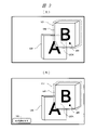
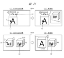
- FIG. 1 shows a configuration outline and a display example of the head-mounted information processing device (HMD) 1 which is the display device of the first embodiment.
- FIG. 1 shows a schematic configuration of the appearance of the user U1 with the HMD1 attached to the head. Further, FIG. 1 shows how the user U1 sees an image of a three-dimensional object displayed in the field of view 101 by the HMD1. Further, FIG. 1 shows an example of changing the display mode of the object in the field of view 101.
- (A) is a display example before the change, and shows a case where the objects of "A" and "B" have a shielding obstruction relationship.
- (B) is a display example after the change, and shows a state in which the obstruction obstruction relationship is temporarily eliminated in the objects "A" and "B".
- the HMD1 is attached to the head of the user U1 and displays an image of an object or the like within the field of view 101 of the user U1.
- the field of view 101 is associated with the display surface 11 of the display device provided in the HMD 1.
- An object is an individual entity object that is a part of an entity or a virtual object that is three-dimensionally arranged.
- the user U1 can visually recognize, for example, the objects 102 and 103 within the field of view 101.
- the object 102 is a virtual object described as "B" in a rectangular parallelepiped shape.
- the object 103 is a virtual object described as "A" in a rectangular parallelepiped shape.
- the object 102 When viewed from the user U1, the object 102 is arranged on the rear side with respect to the object 103 arranged on the front side.
- the front object 103 shields at least a part of the rear object 102, which hinders the visibility of the object 102, in other words, makes it difficult to see.
- Such objects 102 and 103 (a set of two objects) are described as objects and the like that are in a "shielding obstruction relationship" for the sake of explanation.
- the line of sight of both eyes of the user U1 includes the line of sight 104 of the left eye and the line of sight 105 of the right eye.
- the gaze point 106 which is the position where the user U1 is gazing in the three-dimensional space, can be calculated from the directions of the eyes 104 and 105 of the user U1.
- An object located in the vicinity of the gazing point 106 for example, an object 102 of "B", is associated with a desired object that the user U1 gazes at and visually recognizes as a target / target.
- the HMD1 determines and determines such an object as a target object based on the line of sight of both eyes and the gazing point.
- the object 102 of "B" where the gazing point 106 is located is determined as the target object.
- the HMD1 sets a target viewing range 107 for the target object.
- the target viewing range 107 is a range that is related to the target object and is estimated to be visible by the user U1.
- the object 103 of "A" on the front side shields a part (for example, the lower left part) of the target viewing range 107 of the object 102 of "B” which is the target object that the user U1 intends to see. ..
- the user U1 is prevented from visually recognizing the entire target viewing range 107 of the object 102 of the target object "B” by the object 103 of "A” to be shielded.
- the HMD1 determines and detects such an object that interferes with visual recognition as an obstructing object.
- the HMD1 grasps the relationship between objects such as "A" and "B” as a "shielding obstruction relationship".
- the HMD1 changes the display mode of these objects when there is such a shielding obstruction relationship.
- the HMD 1 changes, for example, the display mode of the object 103 of "A", which is a disturbing object that shields the target viewing range 107.
- the HMD 1 changes the display position of the object 103 of "A” to a position outside the target visual field range 107 within the visual field range 101.
- the HMD1 moves the object 103 to a vacant position outside the target viewing range 107 and replaces it with the state of the moved object 103a.
- the HMD 1 makes the entire target viewing range 107 unobstructed.
- the HMD1 may determine the original display position of the object 103 and the display position after the movement so as not to be separated from the target object as much as possible.
- the example of changing the display mode of the object related to the obstruction obstruction is an example of changing the display position on the obstruction object side, but the present invention is not limited to this, and various change methods described later are possible.
- Information / data such as virtual objects may be generated in HMD1 or generated outside the HMD1, for example, in the information server 120 and supplied to the HMD1 via an external network. ..
- the information server 120 can handle a large amount of information, and can, for example, generate and hold a high-quality, high-definition virtual object.
- the external device may also be a user's mobile information terminal, a home device, or the like.
- the gaze point in the three-dimensional space that can be calculated from the two gaze directions 104 and 105 in FIG. 106 is used.
- the HMD1 can determine the object closest to the position of the gazing point 106 as the target object.
- Other means include pointers by remote controllers, voice input, gesture recognition by hand, and the like.
- the HMD1 may determine an object in which the pointer is located within the field of view 101, or an object designated by the pointer on operation, as a target object.
- the user U1 inputs information for identifying the displayed object by voice.
- the HMD1 recognizes the input voice and recognizes, for example, "B"
- the object 102 of "B” may be determined as the target object.
- FIG. 2A shows the classification of "objects".
- the two types of objects are described as “individual entity objects” and “virtual objects". These objects are elements that can constitute an obstruction-blocking relationship.
- these objects are objects that can be arranged three-dimensionally in the field of view 101 corresponding to the display surface 11. That is, these objects are objects that can be arranged in the front-rear direction in the depth direction when the field of view 101 is viewed from the viewpoint of the user U1. Objects placed in front and behind may overlap each other, resulting in a shielding obstruction relationship.
- This object is not necessarily an image (pointing to an image generated by a display device).
- An "individual entity object” is an object based on an entity (in other words, a real image). In the case of the video see-through type, the “individual entity object” is an image of an individual entity cut out from the entity. In the case of the optical see-through type, the “individual entity object” is an individual entity cut out from the entity (in other words, recognized), not an image.
- a “virtual object” is an image of any virtual object produced by a display device in relation to or independently of the entity.
- FIG. 2 shows the pattern of the occlusion obstruction relationship of the object in the first embodiment.
- the individual entity object is arranged on the front side with respect to the individual entity object on the rear side.
- the virtual object is arranged on the front side with respect to the individual entity object on the rear side.
- an individual entity object is arranged on the front side with respect to the virtual object on the rear side.
- the virtual object is arranged on the front side with respect to the virtual object on the rear side.
- the HMD1 of the first embodiment is applicable to the display mode change in the case of each of these patterns, with some exceptions.
- Display example 3 to 8 show various examples of changing the display mode as display examples in the field of view 101 corresponding to the display surface 11 of the HMD 1.
- (A) of FIG. 3 shows an object of "A” which is an obstruction object on the front side as a display mode change when there is a shielding obstruction relationship between the objects of "A” and "B” as shown in (a) of FIG.
- This is an example of making adjustments to increase the transparency (in other words, transparency) of 103.
- the obstructing object is transparent, so that the inside of the target viewing range 107 of the object 102 of "B", which is a partially shielded target object, can be easily visually recognized.
- the user U1 can visually recognize the entire target viewing range 107 of the target object.
- HMD1 shows a case where the transparency of only the portion 103X of the image area of the object 103, which is the obstruction object on the front side, is obscured by the target viewing range 107 on the rear side, and the transparency is adjusted to be close to transparency. .. By this transparency increase adjustment, the degree of visual obstruction can be reduced.
- HMD1 is an example of adjusting the transmittance to the maximum only for the portion 103X of the obstructing object on the front side that shields the target viewing range 107. That is, the portion 103X having the maximum transparency is hidden.
- the target viewing range 107 of the object 102 of "B" on the rear side temporarily comes to the front side of the object 103 of "A".
- the target visual recognition range 107 is not shielded at all, and the visual obstruction can be eliminated.
- FIG. 4 is another example, and shows a case where the same transparency up adjustment is performed for all the objects 103 of "A" which are obstructing objects. As a result, all of the obstructing objects can be seen through, and the target viewing range 107 can be easily seen. At the same time, since the disturbing objects are displayed with the same transparency, it is easy to check the disturbing objects.
- FIG. 4 is another example, and shows a case where all the objects 103 of "A", which are obstructing objects, are hidden to the maximum transparency. In this case, since the obstructing object cannot be seen at all, it is easy to confirm the entire target viewing range 107. As shown in the examples of FIGS. 1 to 4, the visual obstruction of the target visual range of the target object due to the obstructing object can be eliminated by changing the display mode, or the degree of the visual obstruction can be reduced.
- FIG. 5 shows an example of another display mode change.
- the change from (a) to (b) in FIG. 5 shows a case where the object 103 of "A", which is an obstructing object, is reduced and the transparency is increased.
- the object 103 of "A" is replaced with the object 103b after the change.
- the HMD1 resizes the target object to make the obstruction object smaller.
- the degree of visual obstruction due to the obstructing object can be further reduced.
- only the reduction of the obstructing object may be performed, and the effect of facilitating the confirmation of the target viewing range can be obtained.
- FIG. 5 shows a case where the disturbing object of “A” is changed to be enlarged toward the target object of “B”.
- the object 102 of "B” is replaced with the enlarged object 102c after the change. Even in this case, the effect of facilitating the confirmation of the target viewing range can be obtained.
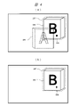
- FIG. 6 shows an example of changing the display mode of the target object instead of the disturbing object.
- the target object is a virtual object and the obstructing object is a virtual object or an individual entity object that is not suitable for adjusting the transparency increase or changing the display position from the viewpoint of visual discomfort of the user U1 rather than the target object.
- FIG. 6 shows a case where the display position of the target object is changed.
- the object 109 of "C” is arranged on the front side, and the object 102 of "B” which is a virtual object is arranged on the rear side.
- the target object is the object 102 of "B”.
- a part of the target viewing range 107 of the target object of "B” is shielded by the object 109 of "C”.
- the object 109 of "C” on the front side is a virtual object or an individual entity object that is not suitable for transparency increase adjustment, display position change, or the like.
- (B) shows the changed state.
- the HMD1 moves the display position of the object 102 of the target object “B” out of the shielding range of the object 109 of the obstruction object “C”.
- the object 102 and the target viewing range 107 of “B” are replaced with the moved object 102b and the target viewing range 107b.
- the entire target viewing range 107b can be seen.
- the gaze point of the user U1 moves from the gaze point 106, for example, to the gaze point 106b.
- the user U1 can visually recognize the entire target viewing range 107b of the moved object 102b located at the gazing point 106b. This is equal to the full viewing of the target viewing range 107 of the original object 102.
- the HMD1 When the target object is moved, the HMD1 is moved to a vacant position within the field of view 101, that is, a position that does not interfere with the visibility of other objects.
- the left side of the "B" and "C” objects is empty, so they are moved to the left side.
- FIG. 7 shows an example of another display mode change.
- the HMD1 may move both the target object and the obstruction object with respect to the objects "A" and "B" that are in a shield obstruction relationship. Moving both objects is effective when the angle of view of the display is small.
- the object 102 of the target object "B” and the object 103 of the obstruction object "A” are moved in a direction away from each other (in this example, the left-right direction). ..
- the entire target viewing range 107 can be seen.
- FIG. 8 shows a method of displaying a duplicate object instead of moving an object as another method of changing the display mode.
- HMD1 displays the object 102 of "B", which is a target object partially shielded by the object 103 of "A", which is a disturbing object, as it is. ..
- the HMD1 creates a duplicate object 102r of the object 102 of "B” and displays it at a vacant position (for example, a position on the left side).
- the HMD1 may display the duplication object 102r as well as information for informing the user U1 that the duplication is a duplication.
- the HMD1 makes the entire target viewing range 107r of the duplicate object 102r visible.
- the user U1 can visually recognize the entire target viewing range 107r of the duplicate object 102r from the gazing point 106r after the movement. This is equal to the full viewing of the target viewing range 107 of the original object 102.
- the user U1 can visually recognize the entire target object using the duplicate object and can grasp the arrangement relationship between the original "B" object 102 and the "C" object 103 as it is.
- the HMD 1 of the first embodiment has the display position, transparency, size, duplication, etc. of at least one object when at least a part of the target viewing range of the target object is obstructed by the obstructing object. Change the display mode.
- Each change method can also be applied in combination. As a result, it is possible to eliminate the visual obstruction of the target object by the obstructing object or reduce the degree of visual obstruction.
- the HMD1 determines the details of the display mode change in consideration of the details of the shielding interference relationship. For example, the HMD1 changes the display mode on the target object side when it is not suitable to change the display mode of the disturbing object.
- the HMD1 temporarily changes the display mode of the objects as in the above example when there is a shielding interference relationship between the objects.
- the HMD 1 may output the user U1 using a GUI or the like so as to clearly inform the user U1 that the display mode has been temporarily changed.
- the HMD 1 may display an image indicating that the display mode is being changed on the display surface.
- Image 130 in FIG. 3B is an example.
- the HMD1 may express the changed state by using an animation, an effect, or the like when changing the display position of the object, or display the changed object in a specific color or the like. May be good.
- the HMD1 may temporarily lock the gaze point determination process during the process of changing the display mode. As a result, it is possible to prevent the target object from being erroneously determined when the gazing point 106 moves with the change of the object display position in FIG. 6, for example.
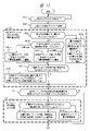
- FIG. 9 shows a main processing flow for explaining the basic operation of the HMD1 of the first embodiment.
- the flow of FIG. 9 has steps S1 to S8.
- step S1 the HMD1 detects the gazing point 106 that the user U1 is gazing at in space based on the detection of the line of sight (104, 105) of both eyes of the user U1 of FIG.
- the HMD1 determines and determines a target object presumed to be a desired object that the user U1 is trying to visually recognize based on the detected position of the gazing point 106.
- HMD1 knows the position of each object and the position of the gazing point 106 in the three-dimensional space, the positions are compared, and for example, the object closest to the position of the gazing point 106 is targeted. Can be judged and confirmed as an object.
- the target object is determined using the gazing point 106, but a modified example will be described later.
- the HMD1 selects and determines the target viewing range presumed to be intended to be visually recognized by the user U1 with respect to the determined target object.
- the target viewing range is selected as the same image area as the apparent display range of the target object (an image area having pixels along the shape).
- the target viewing range may be selected as an image area (for example, a circumscribed rectangle, an circumscribed ellipse, etc.) including the target object.
- the target viewing range may be an area such as a rectangle or an ellipse having a predetermined size centered on the gazing point.
- step S3 the HMD 1 determines whether or not there is an obstructing object that obstructs the target viewing range of the determined target object. For example, the HMD 1 may determine that an obstructing object exists when a predetermined ratio or more of the target visual recognition range is shielded by an object on the front side. If the obstructing object exists (Y), the process proceeds to step S4, and if it does not exist (N), step S4 is skipped.
- step S4 the HMD 1 changes the display mode of the target object so as not to block the target viewing range of the target object.
- a suitable method can be selected from the display position, transparency, size, duplication, and the like for at least one of the obstructing object and the target object.
- the HMD 1 selects a method of changing the display mode of the target object when the disturbing object is less suitable for changing the display mode than the target object.
- step S5 when the display mode is changed, the HMD 1 maintains the state after the display mode is changed for a certain period of time. As a result, the user U1 can visually recognize the entire target viewing range of the target object in that state. When there is no obstructing object (S3-N), the user U1 can visually recognize the entire target viewing range of the target object even if the display mode is not changed.
- step S6 the HMD1 determines whether the gazing point of the user U1 has moved out of the target viewing range of the target object. If the gazing point does not change and is within the target viewing range (S6-N), the process returns to step S5. As a result, the state in which the display mode is changed is maintained as it is, and the state in which the target viewing range can be visually recognized is maintained.
- step S7 the HMD 1 restores the display mode change state of the target object and the obstruction virtual object having the obstruction obstruction relationship to the original state before the change.
- step S8 the HMD1 confirms whether the control process is continued or ended based on, for example, the state of gaze.
- the process returns to step S1 and the detection of a new gaze point is repeated in the same manner.
- the end Y. This flow ends.
- the visual obstruction in the target visual range can be eliminated or the degree of the visual obstruction can be reduced by changing the display mode of the object. ..
- the display mode change state is maintained for a certain period of time according to the state of the gazing point, but the present invention is not limited to this, and when the user U1 inputs a predetermined operation, the line of sight or the gazing point is predetermined. When it is detected that the state of is reached, the display mode change may be terminated.
- FIG. 10 shows an example of a functional block configuration of the HMD1 which is the display device of the first embodiment.
- the configuration is basically the same for other types of display devices.
- the components are mounted on one device, but the present invention is not limited to this, and some components may be separately mounted on another device.
- the HMD 1 includes a processor 410, a memory unit 420, a camera unit 431, a distance measuring sensor 440, a left eye line of sight detection unit 432, a right eye line of sight detection unit 433, a display processing unit 434, an operation input unit 435, and a microphone 436.
- Headphones 437, vibration generating units 438, and communication units 439 are appropriately used, and the components are connected to each other via a bus 450.
- the processor 410 is composed of a CPU, ROM, RAM, etc., and constitutes an HMD1 controller.
- the processor 410 executes processing according to the operating system (OS) 422 stored as the control program 421 in the memory unit 420 and the operation control application program 423.
- OS operating system
- the processor 410 controls each component and realizes functions such as an OS, middleware, and applications, and other functions.
- the memory unit 420 is composed of a non-volatile storage device or the like, and stores various programs 421 and information data 424 handled by the processor 410 or the like.
- the information data 424 includes gaze point information 425 indicating the position of the gaze point to be watched by the user U1, target object information 426 showing the shape and position of the target object visually recognized by the user U1, the shape and position of the virtual object, and the like.
- the virtual object information 427 and the like to be represented are stored.
- the camera unit 431 captures the field of view / visual field state around the front of the HMD1 and acquires an image by converting the light incident from the lens into an electric signal by an image sensor.
- the user U1 directly visually recognizes the actual object in the field of view / visual field around the front.
- the camera unit 431 photographs an entity in the field of view / field of view around the front, and the image of the photographed entity is displayed on the display device of the display processing unit 434.
- the distance measuring sensor 440 is a sensor that measures the distance between the HMD 1 and an entity in the outside world.
- a TOF (Time Of Flight) type sensor may be used, or a stereo camera or another type may be used.
- the HMD1 grasps the three-dimensional arrangement information of the real object in the outside world by using the distance measuring sensor 440 and the arrangement data, and displays the object reflecting the shielding relationship between the individual actual object and the virtual object.
- HMD1 may refer to the arrangement data of the substance of the outside world, including the shielded one, based on some feature points of the substance of the outside world. This arrangement data may be created or held by the HMD 1, or may be acquired from an external information server 120 or the like.
- the left eye line-of-sight detection unit 432 and the right eye line-of-sight detection unit 433 detect the line of sight (104, 105) by capturing the movements and directions of the left eye and the right eye, respectively.
- this line-of-sight detection process a well-known technique generally used as an eye tracking process can be used.
- infrared rays are irradiated to the face from an infrared LED (Light Emitting Diode) and photographed with an infrared camera, and the position of the reflected light generated by the irradiation on the cornea is used as a reference point for corneal reflex.
- a technique for detecting a line of sight based on the position of the pupil with respect to the position of is known.
- Another method is also known in which an eye is photographed with a visible light camera, the reference point is the inner corner of the eye, the moving point is the iris, and the line of sight is detected based on the position of the iris with respect to the inner corner of the eye.
- the intersection of the left eye line of sight 104 detected by the left eye line of sight detection unit 432 and the right eye line of sight 105 detected by the right eye line of sight detection unit 433 is detected as the gaze point 106 that the user U1 gazes at.
- the display processing unit 434 is composed of a display device and a part that performs display processing.
- the display processing unit 434 has, for example, a projection unit that projects light corresponding to a virtual object, notification information to a user, etc., and an image display of the projected light in front of the eyes. It has a transparent half mirror to make it.
- the display surface 11 in FIG. 1 corresponds to a half mirror.
- the display processing unit 434 includes an image of an actual object (including an individual object cut out) taken by the camera unit 431 and an image of a generated virtual object or the like. It has a display device such as a liquid crystal display panel that displays together. In this case, the display surface 11 corresponds to a screen such as a liquid crystal display panel.
- the user U1 can visually recognize the real object in the field of view in front of him and the virtual object in a state of being overlapped with each other by using the HMD1.
- the operation input unit 435 is an input means using, for example, a keyboard, key buttons, touch keys, etc., and can set and input information that the user U1 wants to input.
- the operation input unit 435 is provided at a position and a form in which the user U1 can easily perform an input operation on the HMD1.
- the operation input unit 435 may be provided in a form separated from the HMD1 main body and connected by wire or wirelessly, such as a remote controller.
- the HMD1 displays a graphical user interface (GUI) such as an input operation screen on the display surface 11 of the display processing unit 434, and the line of sight detected by the left eye line of sight detection unit 431 and the right eye line of sight detection unit 432 is directed.
- GUI graphical user interface
- Input operation information may be imported according to the position on the input operation screen.
- the HMD 1 may display a pointer on the input operation screen, and the user U1 may operate the pointer by the operation input unit 435 to capture input operation information. Further, the HMD 1 may collect the voice representing the input operation uttered by the user U1 with the microphone 436 and capture the input operation information.
- the microphone 436 collects external voices and user's own voices.
- the HMD1 can take in the instruction information by the voice uttered from the user U1 and execute the operation for the instruction information with ease.
- the headphone 437 is attached to the ear of the user U1 and outputs voice such as notification information to the user U1.
- the vibration generation unit 438 generates vibration under the control of the processor 410, and converts the notification information and the like transmitted by the HMD 1 to the user U1 into vibration.
- the vibration generating unit 438 can surely convey the notification to the user U1 by generating the vibration at the head of the user U1 to which the HMD1 is closely attached, for example.
- Examples of the notification information to the user U1 include a notification when a disturbing object occurs, a notification notifying the display mode change, a notification of the display mode change method, a notification of the existence of a shared user described later, and the like. Such notifications can further improve usability.
- the communication unit 439 performs wireless communication with other nearby information processing terminals such as HMDs and smartphones, or an external device such as the information server 120 in FIG. 1 by short-range wireless communication, wireless LAN, base station communication, or the like. It is a part having a communication interface to be performed, and includes a communication processing circuit, an antenna, and the like corresponding to various predetermined communication interfaces.
- the short-range wireless communication includes, for example, communication using an electronic tag, but is not limited to this, as long as the HMD 1 can wirelessly communicate with another information processing terminal in the vicinity.
- Examples of such communication interfaces are Bluetooth (registered trademark), IrDA (Infrared Data Association, registered trademark), Zigbee (registered trademark), HomeRF (Home Radio Frequency, registered trademark), or Wi-Fi (registered trademark). And other wireless LANs. Further, as the base station communication, long-distance wireless communication such as W-CDMA (Wideband Code Division Multiple Access, registered trademark) or GSM (Global System for Mobile Communications) may be used.
- W-CDMA Wideband Code Division Multiple Access, registered trademark
- GSM Global System for Mobile Communications
- the communication unit 439 may apply other means such as optical communication and sound wave communication as wireless communication means.
- a light emitting / receiving unit and a sound wave output / sound wave input unit are used, respectively.
- the amount of data is dramatically large.
- a high-speed large-capacity communication network such as 5G (5th Generation: 5th generation mobile communication system) or local 5G is used for wireless communication, usability can be dramatically improved.
- the arrangement data (in other words, the spatial data) of the substance in the outside world may be acquired by communication from an external device such as the information server 120 of FIG. 1 and used.
- This arrangement data is data that shows the arrangement (including the position, shape, etc.) of individual entity objects in a three-dimensional space.
- This arrangement data is, for example, data including various facilities and the like as individual entity objects in the space on the map.
- the arrangement data may have attribute information and related information (for example, the name and description of the facility) for each individual entity object.
- this placement data is data that includes individual entity objects such as walls and placements within the space of a building.
- a virtual object generation processing unit 411 As each component realized based on the processing by the processor 410 of FIG. 10, a virtual object generation processing unit 411, a gazing point detection processing unit 412, a target object target viewing range identification processing unit 413, an obstruction object discrimination processing unit 414, and an object It has a category processing unit 415 and an object display mode control processing unit 416.
- the virtual object generation processing unit 411 generates a virtual object that is an object in a virtual space different from the real space.
- the HMD 1 may take in and use the data of the virtual object generated by the external device such as the information server 120 by wireless communication.
- the gaze point detection processing unit 412 detects the gaze point 106, which is the intersection of the gaze directions of both eyes in FIG. 1 and is the gaze destination of the user U1, by the left eye gaze detection unit 432, and the left eye gaze 104 and the right eye gaze. It is calculated and detected three-dimensionally from the line of sight of the right eye detected by the detection unit 433.
- the target object target viewing range identification processing unit 413 determines the object on which the gazing point is located, in other words, the target object which is the object closest to the gazing point, and presumes that the user U1 intends to visually recognize the target object.
- the target viewing range 107 (FIG. 1), which is the range to be set, is identified and determined.
- the obstruction object discrimination processing unit 414 discriminates the obstruction object, which is an object that overlaps with the target visibility range of the target object and obstructs the target visibility range by shielding in the depth direction as seen from the user U1.
- the object category processing unit 415 classifies objects into predetermined categories (in other words, types) according to the degree of restriction and tolerance for changes in the display mode of the objects.
- the HMD1 determines the method and detailed contents of changing the display mode according to the category of the object. The number and details of categories are not limited.
- the object display mode control processing unit 416 performs control processing for changing the display mode of objects having a shielding obstruction relationship.
- the display mode change is at least one of movement of the display position, adjustment of transparency, size change (reduction / enlargement), display of duplicate objects, and the like.
- the HMD 1 is an object display mode control processing unit.
- 416 controls the display mode change of the objects having a shielding obstruction relationship.
- the object display mode control processing unit 416 changes the display mode of at least one of the jamming object and the target object so as to eliminate or reduce the shielding jamming of the target object by the jamming object.
- the object display mode control processing unit 416 determines the object to be changed, the display mode change method, and the like in consideration of the categories of the objects before and after the obstruction-obstructing relationship.
- the object display mode control processing unit 416 for example, when the obstruction object is a virtual object (second pattern / fourth pattern in FIG. 2) and the obstruction object has a lower limit than the target object, the obstruction object is obstructed. Change the display position of the obstructing object or adjust the transparency so as to eliminate or reduce the obstruction of the target object by the object. Further, the object display mode control processing unit 416 performs a case where the target object on the disturbed side is a virtual object (third pattern / fourth pattern), and the target object has a lower degree of restriction than the disturbing object. Changes or reduces the display position of the target object so as to eliminate or reduce the obstruction of the target object by the obstruction object. As a result, it is possible to eliminate the visual obstruction of the target visual range of the target object by the obstruction object, or to reduce the degree of visual obstruction.
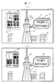
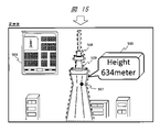
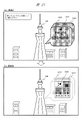
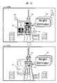
- FIG. 11 shows a display example of the HMD1 in the field of view 101, and schematically shows an example of an individual physical object, a virtual object, and a target visual field.
- FIG. 11A as an example of the actual object, there is a landscape seen by the user U1 from a high place, and the tower 508, the building 500, and the like are included in the landscape. From this landscape, the HMD1 recognizes, for example, a tower 508 or the like as an individual entity object.
- the HMD1 cuts out the part of the tower 508 as an individual entity object from the image of the landscape.
- the HMD1 recognizes the part of the tower 508 as an individual entity object from the landscape.
- the above-mentioned arrangement data may be used when recognizing the tower 508 or the like.
- the HMD1 When focusing on the tower 508, which is an individual entity object, the HMD1 generates an explanatory panel 503 and a guide map 504 as an example of a virtual object related to the tower 508, and superimposes the tower 508 on the landscape including the tower 508.
- the explanation panel 503 is a virtual object that displays explanatory information (for example, height 634 m) about the tower 508 as, for example, a balloon-shaped panel.
- the explanation panel 503 is arranged on the right side so that the starting point of the balloon is in contact with the tower 508.
- the guide map 504 is a virtual object that guides the position of the tower 508 on the map.
- the guide map 504 is arranged in the upper left of the field of view 101.
- the gaze points 501, 502, and 507 are examples of the gaze points of the user U1 for this landscape.
- the gazing point 507 is a case of gazing at the tower 508, which is an individual entity object.
- the HMD 1 may display an explanatory panel 503 or the like, which is a virtual object, depending on the gaze at the tower 508.
- the HMD1 cuts out a part of the tower 508 which is the entity from the landscape as an individual entity object based on analysis and arrangement data. recognize. Then, the HMD1 determines the display range indicated by the broken line of the individual entity object, which is the tower 508, as the target viewing range 509.
- the gaze point 501 is a case of gazing at the explanation panel 503, and the gaze point 502 is a case of gazing at the guide map 504.
- the HMD1 sets the target viewing range of the target object with the object in which the gazing point of the user U1 is located as the target object.
- the HMD1 determines the display range (corresponding image area) of the virtual object as the target viewing range.
- the display range indicated by the broken line of the explanation panel 503 is the target viewing range 505.
- the display range indicated by the broken line of the guide map 504 is the target viewing range 506.
- each target viewing range shown by the broken line is the same range according to the shape and area of the object on the display, but it is not limited to this.
- the target viewing range may be a range larger than the object or a range smaller than the object.
- the target viewing range may be a predetermined size or shape (for example, a rectangle or an ellipse).
- the target viewing range 511 shows a case where an ellipse substantially including the building 500 is set as the target viewing range when the building 500 is a target object.
- FIG. 11B shows another setting example of the target viewing range.
- the HMD1 may control the object (virtual object or individual entity object) related to the object (virtual object or individual entity object) in which the gazing point is located to be included in one target viewing range together.
- the explanatory panel 503 is a related virtual object that is preferably displayed together with the tower 508 with respect to the individual entity object called the tower 508 in which the gazing point 507 is located.
- the HMD 1 relates two display ranges shown by a broken line in the figure, in which the target viewing range 509 of the tower 508 in (A) and the target viewing range 505 of the explanatory panel 503 are combined into one. It is set as one target viewing range 510 for the object (508,503).
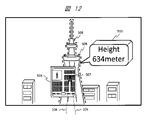
- FIG. 12 shows another display example.
- the relationship between the position of the gaze point in the depth direction and the position of the object is not clear, and the target object (close to the gaze point) where the gaze point is located. It may be difficult or impossible to judge (object, etc.).
- the individual entity object which is the tower 508 and the virtual object which is the guide map 504 overlap with each other in the line-of-sight direction corresponding to the gazing point 507, and the guide map 504 shields a part of the tower 508. is doing.
- HMD1 cannot determine which object is the target object.
- the HMD1 selects and determines the target object based on the visual value (in other words, the importance) of the object for the user U1. For example, HMD1 compares a plurality of candidate objects (508, 504), prioritizes them from the viewpoint of visual value and importance, determines the object with the highest priority as a target object, and determines the target object of the target object. Set the display range as the target viewing range.
- the individual entity object is prioritized over the virtual object as a criterion for determining the prioritization based on this visual value.
- general visual values for example, the prominence of facilities on a map
- the HMD 1 determines that the tower 508 has a higher priority than the guide map 504, sets the individual entity object that is the tower 508 as the target object, and sets the target viewing range 509.
- the target viewing range of the target object that the user U1 wants to see can be optimally selected and determined.
- the gaze point 106 is information shown for explanation and is not actually displayed on the display surface 11.
- the HMD 1 may display an image such as a mark representing the gazing point on the display surface 11 in accordance with the position of the gazing point 106.
- the image such as the gaze point mark may be an image different from the pointer for operation, or may be an image having the same function.
- the pointer is information for specifying a position by, for example, an OS or an application.
- the target object may be selected by using an image such as a gazing point mark or a pointer.
- the objects are classified into three categories as the attributes of the objects used for controlling the display mode change.
- FIG. 2C shows three categories.
- the first category is an object or an individual entity object that has the highest degree of restriction on the display mode change and causes a sense of discomfort due to the display mode change. Examples of the object that causes a sense of discomfort due to the change in the display form include an object in which a virtual object is fixed to an entity, an object in which a virtual object is embedded in an entity, and an object that is integrally deformed. Further, in the case of the optical see-through type, the entity or the individual entity object is classified as the first category because it is difficult to change the display mode.
- a hole is expressed and fixed as a virtual object in a part of a real wall (corresponding individual entity object). Alternatively, it may be incorporated. Since this wall and the hole should be treated as one without separating, they are integrated as a related object and are regarded as the first category with the highest degree of restriction.
- the second category is an object with a lower degree of restriction and a higher tolerance than the first category, although it is subject to some restrictions regarding the change of display mode.
- the second category includes virtual objects such as the explanatory panel 503 (FIG. 11) displayed in relation to the virtual objects and individual entity objects of the first category, for example.
- the third category is an object with a lower degree of restriction and a higher tolerance than the second category, in other words, the object with the lowest degree of restriction among the three.
- the third category includes virtual objects such as a guide map 504 (FIG. 11), which has no or low display position or other relationship restrictions with respect to an entity or other virtual object.
- the third category is an independent virtual object or an object that can be moved to a display position where the user U1 can visually recognize the object without any unnaturalness.
- the tower 508 which is an individual entity object, is the first category.
- the guide map 504, which is a virtual object, is a third category because it is an object that does not look unnatural even if it is moved.
- HMD1 may perform display mode change processing according to the object category classification in the object category processing unit 415.
- HMD1 compares the category of the target object and the category of the obstructing object according to the degree of restriction regarding the change of the display mode in the objects having the obstruction obstruction relationship.
- the HMD1 determines the object to be changed and the method and details of changing the display mode based on the comparison result.
- the object display mode control processing unit 416 changes the display mode of the jamming object when the target object is in a category that is not lower (that is, the same or higher) than the jamming object.
- the object display mode control processing unit 416 changes the display mode of the target object when the target object is in a category having a lower degree of restriction than the obstructing object.
- the HMD1 can eliminate or reduce the visual obstruction of the target visual range of the target object in an optimum form according to the degree of limitation for each object. Further, the HMD1 can minimize the discomfort of visual recognition due to the change of the display mode for both the target object and the obstructing object.
- the display mode of the obstruction object is changed.
- the degree of restriction is the same between the target object and the obstructing object
- the display mode of the target object may be changed. In this case, it is a method of giving priority to maintaining the display mode of the obstructing object on the front side which is located close to the user U1.
- the HMD1 processes that there is no shielding when there is no appearance information of the portion of the real object on the rear side that is shielded. In this case, since the shielding obstruction relationship does not occur, the display mode does not change. In the flow of FIG. 9, as exception handling, it is treated as no shielding (N) in step S3. Further, the HMD1 processes that there is shielding when there is appearance information of the portion of the real object on the rear side which is shielded, for example, when the appearance information can be obtained from the above-mentioned arrangement data.
- the HMD1 processes that there is shielding when there is appearance information of the portion of the real object on the rear side which is shielded, for example, when the appearance information can be obtained from the above-mentioned arrangement data.
- step S3 it is treated as having a shield (Y).
- the HMD1 sets the individual entity object corresponding to the portion of the entity on the rear side as the target object.
- the HMD 1 creates a duplicate object that duplicates the appearance of the individual entity object that is the target object and displays the duplicate object at an empty position, for example, as in FIG.
- the user U1 can visually recognize the part of the shielded entity by looking at the duplicate object.
- HMD1 may use a method of displaying the duplicated object as it is at the shielded position when the display of the shielded target object is prioritized.
- the duplicated object is superimposed and displayed on the front side of the actual object that is the obstructing object that is blocking. This is the same as the method (FIG. 3) in which the transmittance of the obstructing object that is blocking is adjusted up.
- the HMD1 processes the individual entity object cut out from the video image and treats it as a virtual object, so that the individual entity object is treated as a virtual object.
- the display mode of the above may be changed.
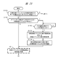
- FIG. 13 shows a processing flow for an operation example such as FIG.
- FIG. 13 is a more detailed processing example with respect to FIG. 9, and includes steps S601 to S613.
- FIG. 13 specifically shows the details of steps S2 and S4 of FIG.
- the HMD1 detects the gazing point of the user U1 by the attention point detection processing unit 412, and determines whether or not there is an object located at the gazing point. If there is an object located at the gazing point, in other words, if one object within a predetermined distance range is determined (Y), in step S602, HMD1 determines that object as the target object.
- step S603 HMD1 determines whether or not there is an object overlapping in the line-of-sight direction of the gazing point, and if there is no object (N), the process proceeds to step S604, and if there is (Y), the process proceeds to step S609.
- step S604 the HMD 1 regards an object that overlaps in the line-of-sight direction of the gaze point as a target object, and determines whether the gaze target object is a real object (corresponding individual real object) or a virtual object. If the target object is a real object (A), the process proceeds to step S605, and if the target object is a virtual object (B), the process proceeds to step S606.
- step S605 the HMD1 identifies and selects the individual entity object individually cut out or recognized from the entity as the target viewing range of the target object.
- step S606 the HMD 1 identifies and selects the display range of the virtual object as the target viewing range of the target object.
- step S607 the HMD1 determines whether there is an object related to the target object which is a real object (S605) or a virtual object (S606).
- the related object is a virtual object or the like whose display position should be linked.
- step S608 the HMD1 identifies and selects the target object and the related object as the target viewing range of one target object ((Y) of FIG. 11 (FIG. 11). B)).
- step S609 the HMD1 selects one object from a plurality of objects overlapping in the line-of-sight direction of the gazing point according to a predetermined criterion, sets the target object as the target object, and identifies and selects the target viewing range of the target object. ..
- the above-mentioned visual value / importance is used.
- the HMD1 sets the object having the highest visual value / importance as the target object among the plurality of overlapping objects, and identifies and selects the display range of the target object as the target visual range.
- the target viewing range of the target object is determined.
- step S3 the HMD 1 determines whether or not there is a virtual object (may be described as "jamming virtual object") as a jamming object that shields the target viewing range of the target object by the jamming object discrimination processing unit 414. Determine. If there is a jamming virtual object (Y), the process proceeds to step S4, and if there is no jamming virtual object (N), step S4 is skipped. In the first embodiment, if there is a virtual object that shields at least a part of the target viewing range, the HMD 1 uses it as a disturbing virtual object and proceeds to step S4.
- a virtual object may be described as "jamming virtual object”
- Step S4 has steps S611 to S613.
- the HMD1 determines, by the object category processing unit 415, whether the target object has a higher degree of restriction than the jamming virtual object, that is, whether the target object has a higher category than the jamming virtual object. For example, if the target object is in the first category and the jamming virtual object is in the second category, the former is higher. If the target object has a higher category than the disturbing virtual object (Y), the process proceeds to step S612, and if not, the process proceeds to step S613.
- the HMD1 performs the above-mentioned display position movement or transparency adjustment as a display mode change of the disturbing virtual object by the object display mode control processing unit 416.
- step S613 the HMD 1 moves the display position or the like as a display mode change of the target object by the object display mode control processing unit 416. As a result, the entire target viewing range can be visually recognized. After that, it leads to the above-mentioned step S5.
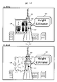
- FIG. 14 shows an operation example in the case of the second pattern.
- the target object is the tower 508, which is an individual entity object of the first category
- the obstruction object is the guide map 504, which is a virtual object of the third category, as a shielding obstruction relationship.
- the target viewing range 509 of the tower 508 where the gazing point 507 is located is partially shielded by the guide map 504.
- the HMD 1 adjusts, for example, to increase the transparency by using the guide map 504, which has a lower degree of restriction and a lower category, as a change target.
- the guide map 504 becomes transparent and the entire target viewing range 509 of the tower 508, which is the target object, can be visually recognized.
- FIG. 15 shows a case where the display position is moved as a display mode change as another operation example.
- the HMD1 moves the display position of the guide map 504 to which the category is lower to a position outside the target viewing range 509 of the tower 508.
- the entire target viewing range 509 of the tower 508, which is the target object can be visually recognized without any shielding.
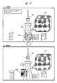
- FIG. 16 shows an operation example in the case of the third pattern.
- FIG. 16 is the opposite of FIG. 14 and the like, the target object is the guide map 504 which is a virtual object of the third category, and the obstruction object is the tower 508 which is an individual entity object of the first category.
- the target viewing range 506 of the guide map 504 with the gaze point 502 is partially shielded by the tower 508.
- the HMD 1 moves the guide map 504 of the lower category to a position outside the tower 508 so that the tower 508 does not overlap within the target viewing range 506.
- the entire target viewing range 506 of the guide map 504, which is the target object can be visually recognized without any obstruction.
- FIG. 17 shows an operation example in the case of the fourth pattern.
- the target object is the explanation panel 503, which is a virtual object of the second category
- the obstruction object is the guide map 504, which is a virtual object of the third category.
- the target viewing range 505 of the explanatory panel 503 is partially shielded by the guide map 504.
- the HMD1 adjusts the transparency of the guide map 504 to which the category is lower.
- the guide map 504 becomes transparent, and the entire target viewing range 505 of the explanation panel 503, which is the target object, can be visually recognized.
- FIG. 18 shows the case of moving the display position as another operation example.
- the HMD1 moves the display position of the guide map 504 to which the category is lower to a position outside the target viewing range 505.
- the entire target viewing range 505 of the explanation panel 503, which is the target object can be visually recognized without any shielding.
- FIG. 19 shows another operation example.
- FIG. 19 is the opposite of the case of FIG. 17, and is a guide map 504 in which the target object is a virtual object of the third category and an explanatory panel 503 in which the disturbing object is a virtual object of the second category.
- the target viewing range 506 of the guide map 504 is partially shielded by the explanatory panel 503.
- the HMD 1 moves the guide map 504 of the lower category to a position where the explanation panel 503 and other objects do not overlap within the target viewing range 506.
- the entire target viewing range 506 of the guide map 504, which is the target object can be visually recognized without any obstruction.
- the same control as when the target object is the first category and the obstruction object is the third category can be applied.
- the visible range of an object such as an entity or a virtual object that the user U1 wants to see is shielded by another object or the like.
- the visual obstruction can be eliminated or reduced by changing the display mode, and the user U1 can suitably visually recognize the entire object.
- such a function can be realized with less effort for the user and with ease of use.
- the user can preferably visually recognize the entire target viewing range of the target object to be gazed at.
- the display mode can be automatically changed according to the shielding obstruction relationship to support the user's visual recognition, such a function can be realized with less effort and usability.
- Patent Document 1 when there is an object that obstructs the visibility of the background in the line-of-sight direction, the display form of the object is changed.
- the first embodiment there is a shielding relationship between objects arranged three-dimensionally, so that when there is an obstructing object that obstructs the visibility of the target viewing range of the target object, the entire target viewing range can be visually recognized. Change the display mode for the jamming object or the target object.
- the HMD1 may determine that there is a target object that the user U1 wants to gaze at when the movement in the line of sight becomes equal to or less than a predetermined threshold value. This eliminates mishandling due to unintended rapid eye movements and makes it possible to identify the target object more accurately. Misprocessing includes that when the gazing point is located on an object in a short time, that object is mistakenly set as the target object.
- the HMD1 may determine the size / area of the image area of the object and set the upper limit when setting the target viewing range.
- the HMD 1 may set an upper limit range corresponding to the predetermined threshold value as the target viewing range. For example, it is difficult to display the target object when the target object is too large in the field of view, or when the disturbing object is moved out of the target visual field as a display mode change. In such a case, it is effective to set the upper limit of the target viewing range.
- the second embodiment will be described with reference to FIG. 20 and the like.
- the second embodiment has the following as an additional function to the first embodiment.
- an object that is a candidate for a target object (sometimes referred to as a target candidate object) may be obscured by another object, a virtual object or an individual entity object, and its existence may not be known to the user. ..
- This function is a function that can confirm the existence of the target candidate object in such a case.
- FIG. 20 is an explanatory diagram of an operation example according to the second embodiment.
- FIG. 20 shows an example of changing the display mode when a certain object (target candidate object) is shielded by an entity.
- (A) shows the state before the change.
- the tower 508 which is an individual entity object
- the explanation panel 1213 which is a virtual object
- the tower 508 As an object located in the direction of the gazing point 1201, there are a tower 508 and a guide map 1202 (indicated by a dotted line) which is a virtual object hidden by the tower 508 and cannot be seen. That is, there is a guide map 1202 as an invisible target candidate object.
- the HMD 1 changes the display mode regarding the object (508, 1202) in the line-of-sight direction as in (b).
- the HMD 1 moves the display position of the guide map 1202 so that at least a part of the guide map 1202, which is a target candidate object, can be seen out of the shield by the tower 508.
- at least a part of the changed guide map 1203 is visible to the user U1.
- the HMD1 may be changed so that the entire display range corresponding to the target candidate object can be seen. Further, the HMD 1 may be in a state where a predetermined ratio portion of the display range corresponding to the target candidate object can be seen.
- the user U1 can recognize and confirm the existence of the guide map 1202.
- the user U1 can select the guide map 1202 as the target object by using the gazing point (the gazing point 1201b after movement).
- FIG. 21 shows another display example.
- a virtual object related to the tower 508 As an object located in the direction of the gazing point 1211, a virtual object related to the tower 508, an explanation panel 1213, and a virtual object hidden by being shielded by the explanation panel 1213.
- the HMD 1 changes the display mode regarding the object (1212, 1213) in the line-of-sight direction.
- the HMD 1 performs, for example, a transparency increase adjustment as a display mode change of the explanation panel 1213 on the front side that shields the guide map 1212 which is a target candidate object.
- the explanation panel 1213 can be seen through and the guide map 1212 behind can be seen.
- the user U1 can confirm the existence of the guide map 1212 which is a target candidate object, and can select the target object by using the gazing point 1211.
- FIG. 22 is a supplementary explanatory diagram relating to a case where a plurality of objects overlap in the line-of-sight direction and it is difficult to determine the target object in which the gazing point is located, as in the example of FIG. 21 and the like.
- FIG. 22 schematically shows the overlap of objects in the depth direction (Z direction) when the field of view 101 is viewed from the user U1.
- the explanation panel 1233 is arranged on the front side close to the viewpoint of the user U1, and the guide map 1232 is arranged on the rear side.
- the guide map 1232 corresponds to the guide map 1212, which is the target candidate object in FIG.
- the explanatory panel 1233 corresponds to an obstruction object in terms of obstruction obstruction.
- the guide map 1212 which is the target candidate object in which the gazing point 1231 is located, is shielded by the explanatory panel 1233, which is an out-of-focus obstruction virtual object, and is hidden from the user U1 as in FIG. can not see.
- An out-of-focus object is an object in which the gazing point is not located or an object having a large distance from the gazing point.
- the gazing point 1231 is an example of the gazing point calculated from the line of sight (104, 105) of both eyes. In this example, in the depth direction (Z direction), the gazing point 1231 is located near the guide map 1232. As the distance from the gazing point 1231 to the object, the distance to the guide map 1232 is the smallest and is within a predetermined distance range. Therefore, the guide map 1232 becomes a target candidate object.
- the HMD1 detects that the explanatory panel 1233 is out of focus depending on the direction of the line of sight and the gazing point.
- the HMD1 performs, for example, a transparency increase adjustment as a display mode change toward the out-of-focus explanatory panel 1233 (similar to FIG. 21).
- the explanation panel 1233b after the change becomes transparent (a state with high transparency), and the guide map 1232 behind it becomes visible, and the user U1 confirms the existence of the guide map 1233 which is a target candidate object. can.
- FIG. 23 shows a processing flow related to the function of confirming the existence of the target candidate object of HMD1 in the second embodiment.
- the flow of FIG. 23 has steps S1100 to S1104 as different portions from the above-mentioned flow. This portion is performed as a preprocessing for step S2 in FIG.
- step S1100 the HMD1 confirms whether the mode corresponding to this function is in the on (enabled) state, and if it is in the on state, performs the subsequent processing.
- the mode can be set or instructed by the user U1 through the operation input unit 435, for example.
- step S1101 the HMD1 has a target candidate object which is an object whose existence is unknown to the user U1 by being shielded by an object (virtual object or individual entity object) on the entire display surface 11.
- This target candidate object is an object that cannot be recognized because it cannot be seen by the user U1 and cannot be selected by the gazing point. If there is such a target candidate object (Y), the process proceeds to step S1102, and if there is no such target candidate object, the process proceeds to step S2.
- step S1102 the HMD1 confirms / waits whether a trigger for performing the existence confirmation process has occurred.
- This trigger is a trigger that allows the user U1 to instruct whether or not to perform the existence confirmation process.
- This trigger can be, for example, when an instruction input is received through the operation input unit 435 or the microphone 436, or when the detected line of sight of the user U1 goes near the target candidate object.
- the HMD1 may display a guide, a button, or the like such as "There is a hidden object. Do you want to display and confirm it?" In the field of view 101, and may be triggered by pressing the button. It is also possible to omit the trigger input step S1102 and automatically perform the object existence confirmation process.
- step S1103 the HMD1 changes the display mode of the target candidate object (moves the display position, duplicates display, etc.) or displays the obstructing object that is shielded by the object display mode control processing unit 416. Make changes (adjustment to increase transparency, etc.).
- step S1104 the HMD1 maintains the state after the display mode is changed for a certain period of time. As a result, the user U1 can confirm the existence of the target candidate object. The user U1 can easily confirm the existence of the target candidate object without requiring a special operation. After step S1104, it leads to the above-mentioned step S2.
- the target candidate object or an obstruction object so that at least a part of the target candidate object can be visually recognized when there is an object that is obscured by the object and its existence is unknown.
- One of the display modes is changed.
- the user U1 can surely confirm the target candidate object and can select it as the target object. If there is an individual entity object that cannot be seen hidden and there is appearance information of the individual entity object, the individual entity object may be treated as a target candidate object and the existence may be confirmed in the same manner.
- the HMD 1 has described the case where the control content is determined by referring to the parameters such as the degree of restriction (in other words, the tolerance) and the visual value (in other words, the importance) with respect to the change of the display mode of each object.
- the degree of restriction or tolerance in the above category is one of the attribute information indicating the degree of restriction or tolerance regarding the change of the display mode for each object.
- limit or tolerance, category, or other information may be set as one of the attribute information.
- the visual value, the importance, the priority, and the like for each object may be set.
- FIG. 24 shows an example of object data managed and held by HMD1.
- This object data is management data including attribute information for each object.
- This object data may be, for example, management information different for each application, or management information or user setting information different for each user.
- the HMD 1 may generate and set each information of the object data by itself, or may refer to the information from an external device (for example, the information server 120 in FIG. 1).
- the table of object data in FIG. 24 has, as columns, an ID, an object, a type, a category, a visual value, a related object, and a shared user.
- the "ID” is an identifier for each "object”. Examples of “objects” are the towers and explanatory panels mentioned above.
- the "type” here is A.
- Individual entity object, B. There are two types: virtual objects. There are three categories (corresponding degree of restriction), for example, 1 (high), 2 (medium), and 3 (low) as described above. There are three visual values (corresponding importance), for example, 1 (high), 2 (medium), and 3 (low).
- the "related object” represents a relationship with another object.
- the “shared user” indicates an identifier of a shared user when the object is shared by a plurality of users as a shared user.
- the “category” and “visual value” may be set by the HMD 1 or may be set by the user.
- the HMD 1 may set the "visual value” based on the general prominence of the object and the like.
- the HMD 1 may set the "visual value” according to the degree of interest of the user U1 in the object.
- a "visual value” is set for each individual entity object such as a facility on a map based on general prominence.
- the “category” may be determined by integrating the "limitation degree” and the "visual value”.
- the HMD1 In addition to the object data, the HMD1 appropriately processes and stores the object information at each time point during the control process.
- This object information has information such as a display position on the display surface 11, a direction of the three-dimensional arrangement of the three-dimensional object, a display range (image area), a target viewing range, and a display mode change state for each object.
- the display mode change state includes whether or not there is a change, a change method, and the like.
- the HMD1 controls the object display by using the object data, the object information, the line of sight, the gaze point, and the like.
- the third embodiment will be described with reference to FIG. 25 and the like.
- the third embodiment has a function of changing the display mode of the shared object among the shared users.
- FIG. 25 is an explanatory diagram of an operation example of the HMD 1 of the third embodiment.
- the first user U1 is using HMD1A and the second user U2 is using HMD1B.
- the virtual objects "A" object 103 and "B" object 102 are shared among these users (U1 and U2).
- Users U1 and U2 are shared users who share those virtual objects.
- the objects "A" and "B” are shared objects shared by the shared users (U1, U2), respectively.
- Communication 2500 for sharing is performed between HMD1 (1A.1B) of the shared users (U1, U2) by the above-mentioned short-range wireless communication.
- FIG. 25 shows a first example of a state such as display and visual recognition.
- Shared users U1, U2 are looking at shared objects (A, B).
- the first user U1 sees the object 103 of "A” where the gazing point P1 by the line of sight E1 is located as a target object in the field of view 101A.
- the HMD1A sets the target viewing range 107A of the object 103 of the "A”.
- the second user U2 sees the object 102 of "B” where the gazing point P2 by the line of sight E2 is located as the target object in the field of view 101B.
- the HMD1B sets the target viewing range 107B of the object 102 of the "B”.
- the object 103 on the rear side "B" viewed by the second user U2 is the target object
- the object 103 on the front side viewed by the first user U1 is "
- the object 102 of "A” is a disturbing object.
- the lines of sight E1 and E2 indicate the above-mentioned lines of sight (104, 105) of both eyes combined into one line, respectively.
- the display content of the visual field range 101A viewed by the user U1 and the display content of the visual field range 101B viewed by the user U2 are shown as the same, but since the viewpoint position of each user is different, the actual display content, That is, the appearance of the object is also different.
- FIG. 26 below shows a second example.
- the first user U1 looks at the object 102 of the rear side “B”
- the second user U2 looks at the object 103 of the front side “A”.
- the object 103 on the rear side "B” viewed by the first user U1 is the target object
- the object 103 on the front side viewed by the second user U2 is "
- the object 102 of "A" is a disturbing object.
- FIG. 27 shows a modified example corresponding to the first example of FIG. 25.
- (A) shows the state before the change of the display mode as the state where the image of the field of view 101A is viewed from the first user U1, and (c) shows the state after the change.
- (B) shows the state before the change of the display mode as the state where the image of the field of view 101B is viewed from the second user U2, and (d) shows the state after the change.
- the HMD1A of the first user U1 generates and displays the mark information m2 in the field of view 101A based on the communication 2500 with the HMD1B of the second user U2.
- This mark information m2 is an image showing which object the second user U2 is looking at, that is, which target object the gazing point P2 of the second user U2 is located on.
- the HMD1B of the second user U2 transmits information indicating that the target object is "B" to the HMD1A
- the HMD1A of the first user U1 transmits information indicating that the target object is "A" to the HMD1B. Send to.
- the HMD1A generates, for example, the mark of the number "2" representing the second user U2 as the mark information m2 according to the information from the HMD1B, and displays it in the vicinity of the object of the target object "B" of the second user U2. do.
- the first user U1 can recognize which shared object the second user U2, which is a shared user, is viewing.
- the HMD1B of the second user U2 represents which object the first user U1 is looking at in the field of view 101B based on the communication 2500 with the HMD1A of the first user U1.
- Mark information m1 is generated and displayed.
- the HMD1B generates, for example, the mark of the number "1" representing the first user U1 as the mark information m1 according to the information from the HMD1A, and displays it in the vicinity of the object of the target object "A" of the first user U1. do.
- the second user U2 can recognize which shared object the first user U1 is looking at.
- the HMD1 (1A, 1B) of each shared user changes the display mode of the object according to the relationship of viewing the shared object between the shared users as described above and the relationship of obstruction of obstruction. You may. Examples are shown in (c) and (d).
- an example of the change from (a) to (c) is as follows. In the state of (a), the object of "B” seen by the second user U2 is shielded behind the target viewing range 107A of the target object of "A" seen by the first user U1. In HMD1A, since the first user U1 can visually recognize the target object of "A" without obstruction of obstruction, the display of the object of "A” is left as it is.
- the object of "B" seen by the second user U2 may be displayed as it is, but is partially shielded when viewed from the first user U1. Therefore, in this example, the HMD1A displays the target object of the shared user "B” so that the place where the second user U2 is looking at the object of "B” can be easily seen by the first user U1.
- change. (C) shows an example of moving the display position of the object of "B” so that the whole can be seen.
- This display mode change may be performed in response to a predetermined input operation by the first user U1 instead of automatically.
- the HMD1A displays "Do you want to check the object that the shared user (2) is looking at?" On the display surface 11, and changes as shown in (c) according to the button pressing operation by the user U1. You may go.
- an example of the change from (b) to (d) is as follows.
- a part of the target object of "B" seen by the second user U2 is obstructed by the object of "A" seen by the first user U1. Therefore, in this example, the HMD1B changes the display mode of the target object of the first user U1 which is the obstruction object so that the entire target object of the “B” can be seen.
- (D) shows an example of moving the display position of the object of "A”. As a result, the second user U2 can confirm the target object of "B”.
- FIG. 3 shows a state after changing another display mode from the state seen from the first user U1 of (a).
- the HMD1A is changed so that the entire object of "B” can be seen by adjusting the transparency of the object of "A” as in (e).
- This change may be made according to a predetermined operation as in the case of (c).
- the first user U1 can confirm not only the target object of "A” but also the target object of "B" of the second user U2.
- (F) shows, as another display example, a state seen from the second user U2 of (b) after another display mode is changed.
- the HMD1B is changed so that the entire target object of "B” can be seen by adjusting the transparency of the object of "A” as in (f).
- the mark information indicating the visual state is displayed.
- the same control as in the case of the first example is applicable.
- FIG. 28 shows another display example.
- (A) shows a state in which the first user U1 is looking at the object of "A" on the front side, as in the first example of FIG. 25 and (a) of FIG. 27.
- (B) shows a state in which the second user U2 is looking at the object of "B" on the rear side, as in the case of (b) in FIG. 27.
- HMD1A changes the display mode as in (c). HMD1A leaves the display of the target object of "A" of the first user U1 and the target object of "B” of the second user U2 as they are, so that the entire contents of the shielded "B" object can be confirmed.
- a duplicate object 102r of the object of "B" is generated and displayed in an unobstructed vacant position. It is more preferable that the position for displaying the duplicate object 102r is determined so as to correspond to the direction in which the second user U2 is located (on the right side in this example). Further, the duplicate object 102r may also be displayed with the mark information m2 representing the shared user gaze object. As a result, the first user U1 can confirm not only the target object of "A” but also the entire target object of "B" of the second user U2.
- the HMD1B changes the display mode as in (d).
- the HMD1B generates a duplicate object 102r (which looks different from the duplicate object 102r of (c)) for the partially shielded target object "B" and displays it at an empty position.
- the HMD1B may leave the target object of "B” as it is and change the display position of the object of "A” which is a disturbing object in the same manner as described above.
- (E) and (f) are other display examples.
- (E) is a state seen from the first user U1. Seen from the first user U1, the object of "B" seen by the second user U2 is partially shielded. The HMD1A changes the display mode of the "B" object of the shared user in the same manner as described above.
- (f) is a state seen from the second user U2. From the viewpoint of the second user U2, the target object of "B” is not shielded by the object of "A" and the whole picture can be seen. Therefore, the HMD1B side does not change the display mode.
- FIG. 29 shows an example of changing the display mode when the shared user (U1, U2) is viewing the same shared object (for example, the object 102 of “B”).
- A is a state seen from the first user U1
- (c) is a state seen from the second user U2.
- the first user U1 is looking at the rear "B” object from the right side of the "A” object.
- the target object of "B” is partially shielded by the object of "A”.
- the second user U2 is looking at the rear "B” object from the left side of the "A” object.
- the target object of "B” is partially shielded by the object of "A”.
- the HMD1A displays the mark information m2 indicating that the second user U2 is also looking at the object of "B".
- the HMD1B displays the mark information m1 indicating that the first user U1 is also looking at the object of "B".
- B) and (d) are examples after changing the display mode of each.
- (B) is an example of changing the display position of the object of "A", which is a disturbing object, to, for example, the position on the left side.
- (D) is an example of changing the display position of the object of "A” which is an obstruction object to, for example, the position on the right side.
- the shielding interference relationship is the fourth pattern described above (FIG. 2), but the control is not limited to this, and the same control is possible with other patterns.
- the individual entity object is a shared object
- the above mark information can be displayed. It is possible to change the display mode for objects other than optical see-through type entities.
- the above-mentioned restrictions and visual values can also be applied to shared objects.
- the display mode change suitable for each HMD1 of each user is displayed on the shared object of the shared user.
- each user can surely visually recognize the shared object without causing any confusion in the visual recognition while eliminating or reducing the visual obstruction due to the shielding between the objects.
- at least one of the HMDs 1 among the shared users displays a mark representing the shared user gaze object, and the display mode is changed according to the relationship between the visual recognition and the obstruction of obstruction.
- the method and details are determined in consideration of not only the above-mentioned occlusion obstruction relationship, limit degree and visual value, but also the visual relationship of which shared object the shared user is viewing. ..
- the first priority should be the display of the entire target object of "A”.
- the "B" object is not a jamming object, but a target object seen by the shared user. Therefore, in the case of the third embodiment, the display mode can be changed so that the entire object of "B" can be confirmed.
- the method and details are selected so that the entire object of both "A" and "B" can be visually recognized.
- the display position movement of (c) is performed.
- the duplicate display method of FIG. 28 (c) may be selected.
- the mark information representing the shared user gaze object is different from the gaze point.
- the mark information is displayed in an area other than the area shielded by other objects in the target viewing range of the object that the shared user gazes at. When it is displayed in the shielded area, it is unclear which object the gaze destination is before or after, so it can be clarified by such a display.
- mutual communication may be performed at all times to update the display state (including mark information) in substantially real time, or communication may be performed periodically to update the display state periodically. You may.
- the display position of the mark information representing the shared user gaze object may be set according to the gaze point.
- a mark indicating the gazing point may be displayed at a position corresponding to the gazing point in the visual field range.
- a pointer for a selection operation by a remote controller or the like may be displayed.
- FIG. 30 is a modified example showing an example in which the mark 3001 representing the gazing point and the pointer 3003 are displayed in the visual field range 101 in addition to the mark representing the shared user gazing object.
- a diamond-shaped mark 3001 is displayed at the position of the gazing point P1 of the first user U1.
- a triangular mark 3002 is displayed at the position of the gazing point P2 of the second user U2.
- a pointer for the operation of the first user U1 for example, a cross-shaped pointer 3003 is displayed.
- FIG. 31 shows a display example in another modified example.
- (A) is a state seen from the first user U1 and is the same as (a) of FIG. 27 described above.
- the first user U1 is looking at the target object of "A" on the front side.
- (B) is a state seen from the second user U2.
- the second user U2 is looking at the rear "B" object from a line-of-sight direction different from the line-of-sight direction of the first user U1, for example, a direction different by 90 degrees.
- the shared object of "B” the shape and location seen from the first user U1 and the shape and location seen from the second user U2 are different.
- the side surfaces of the objects of "A" and "B” seen from the second user U2 are illustrated as "A #" and "B #".
- (C) and (d) indicate the state after the display mode is changed.
- the HMD1A displays the target object of "A” as it is, and changes the display mode of the partially shielded "B" object seen by the shared user for confirmation. ..
- the HMD1A displays the object of "B” so as to have a shape or a position as seen from the second user U2 as shown in (b) as a display mode change.
- the HMD1A leaves the "B” object as it is, and creates and displays a duplicate object 3101 of the "B” object together with a balloon at an empty position.
- the duplicate object 3101 is generated as a duplicate object having the same appearance as the object 3102 in (b).
- the first user U1 can confirm the state as seen from the second user U2 as the whole of the shared object of "B".
- the display may be as it is, or may be as follows.
- the HMD1B displays the object of "A" seen by the first user U1 so that the shape and the portion seen by the first user U1 can be seen in the same manner as described above. Change the aspect.
- the object 3103 of "A" in the appearance of (a) is generated and displayed by superimposing it in front of the object of "A".
- the fourth embodiment will be described with reference to FIG. 32 and the like.
- a modified example of the target object determination method is shown.
- the target object is determined and determined by detecting the gaze point from the user's line of sight.
- a user's selection input operation for the tag displayed attached to each object is accepted.
- the HMD determines the target object.
- FIG. 32 shows a display example in the fourth embodiment.
- the tower 508, which is an individual entity object, the explanation panel 503, which is a virtual object, the guide map 504, and the like are displayed, as described above.
- the HMD1 attaches a tag to each object and displays it in the field of view 101.
- This tag is an image that identifies and makes the object selectable.
- the tag (701,702,703) has a rectangle connected by a leader line from the object and a number that identifies the object.
- the user U1 performs an object selection input operation by using a predetermined operation means provided in the HMD1.
- a predetermined operation means for example, voice input can be used, but the present invention is not limited to this, and various means such as a pointer by a remote controller, gaze detection by a line of sight, and gesture recognition by a hand can be applied.
- object selection by voice input for example, it is as follows.
- the user U1 wants to select the tower 508 as an object, for example, the user U1 inputs the number (“3”) of the tag 703 attached to the object by voice.
- the HMD1 recognizes the input voice number and grasps the object associated with the tag of the number.
- the accuracy of determining the target object can be increased by using the tag selection input reception in the fourth embodiment together. Further, by using the tag selection method in the fourth embodiment, the above-mentioned functions such as changing the display mode can be applied even to a device having no gaze point detection function as the HMD1.
- the guide map 504 overlaps the front side of the tower 508.
- the gaze point 507 of the user U1 overlaps the tower 508 and the guide map 504, and it may be difficult to determine the target object. Even in this case, the target object can be easily determined by using the tag.
- tower 508 is selected as the target object.
- (B) shows the changed state.
- the HMD1 adjusts, for example, the transparency of the guide map 504 that shields the selected tower 508. As a result, the entire tower 508 can be seen.
- the HMD1 may be displayed at all times, may be performed when it is determined that it is difficult to determine the target object only by the gazing point, or may be performed in response to the tag display instruction input by the user U1. good.
- FIG. 33 shows an example applied to a smartphone as a display device or an information processing device of a modified example of the fourth embodiment.
- FIG. 33 shows an example in which each object is tagged and displayed as a display example on the display surface of the smartphone 700. Even in the case of the smartphone 700, the shielding interference relationship between the objects is considered on the premise of a three-dimensional arrangement considering the position in the depth direction. Therefore, the method of changing the display mode of each of the above-described embodiments can be similarly applied.
- the functional block configuration of the smartphone 700 is basically the same as the configuration of FIG. 10. In the smartphone 700, the line-of-sight detection and the gaze point detection are not performed, and other operation input means are used.
- the line-of-sight detection and the gaze point detection may be realized by using another means (for example, the camera unit 431).
- the entity corresponding individual entity object
- the smartphone 700 the entity (corresponding individual entity object) is displayed as an image taken by the mounted camera (camera unit 431).
- the tag selection input reception method and other operation inputs in addition to voice input and the like, selection input by tapping on the touch panel on the display surface is also possible.
- the fifth embodiment will be described with reference to FIG. 34.
- a shielding obstruction relationship between two objects in the depth direction a case where an object on the front side shields and obstructs an object on the rear side is shown. Then, in the case of such a shielding obstruction relationship, an example of changing the display mode so that at least the target object is easily visible is shown.
- the relationship of the object to be changed in the display mode exists in addition to the above-mentioned shielding obstruction relationship.
- the relationship due to the difference in brightness is used as the relationship between the objects when the user visually recognizes a plurality of objects.
- two objects individual entity objects or virtual objects
- the HMD of the fifth embodiment changes the display mode.
- FIG. 34 shows a display example.
- the object 102 of "A” on the front side and the object 103 of "B” on the rear side are arranged.
- the gazing point 106 of the user U1 is located on the object 102 of "A” on the front side, and the object of "A” becomes the target object.
- the user U1 can basically visually recognize the entire object 102 of "A", and does not have the above-mentioned shielding obstruction relationship.
- the difference between the brightness of the object of "A” and the brightness of the object of "B” is large, for example, when the brightness of "B” is larger, "B" is visually recognized for the target object of "A”.
- Objects may interfere. This is not limited to the objects before and after, and even in the case of a non-shielding relationship in which objects are close to each other, such as to the left and right, nearby objects may interfere with the same.
- HMD1 determines the difference in brightness between objects, and determines the disturbing object from the viewpoint of brightness from the difference.
- the HMD1 changes the display mode of the determined obstruction object, for example, the object of "B".
- HMD1 moves the display position so as to move the object of "B” away from the object of "A", for example, as after the change of (b).
- the HMD1 may be changed by moving the target object of "A” or the like.
- the HMD 1 may use a method of temporarily changing the brightness of the object as another method of changing the display mode. For example, HMD1 temporarily reduces the brightness of the "B" object. As a result, the difference in luminance becomes small, and the user U1 can easily see the target object of "A".
- the present invention has been specifically described above based on the embodiments, the present invention is not limited to the above-described embodiments and can be variously modified without departing from the gist. It is also possible to form a combination of each embodiment, or to add, delete, or replace a component.
- HMD head-mounted information processing device
- 11 display surface, U1 ... user, 101 ... field of view range, 102, 103 ... object, 104, 105 ... line of sight, 106 ... gaze point, 107 ... target viewing range, 120 ... Information server.
Landscapes
- Engineering & Computer Science (AREA)
- Theoretical Computer Science (AREA)
- General Engineering & Computer Science (AREA)
- Physics & Mathematics (AREA)
- General Physics & Mathematics (AREA)
- Human Computer Interaction (AREA)
- Multimedia (AREA)
- Computer Graphics (AREA)
- Computer Hardware Design (AREA)
- Software Systems (AREA)
- User Interface Of Digital Computer (AREA)
Abstract
Description
図1等を用いて、本発明の実施の形態1の表示装置および表示方法について説明する。実施の形態1の表示装置は、仮想オブジェクト表示装置であり、ヘッドマウント情報処理装置(HMDと記載する)に適用した場合を示す。実施の形態1の表示方法は、実施の形態1の表示装置で実行されるステップを有する方法である。
図1は、実施の形態1の表示装置であるヘッドマウント情報処理装置(HMD)1の構成概要および表示例を示す。図1では、ユーザU1が頭部にHMD1を装着した状態での外観の模式構成を示す。また図1では、ユーザU1がHMD1によって視界範囲101に表示される3次元的なオブジェクトの画像を見る様子を示す。また図1では、視界範囲101でのオブジェクトの表示態様の変更の例を示す。(a)は変更前の表示例であり、「A」「B」のオブジェクトにおいて遮蔽妨害関係がある場合を示す。(b)は変更後の表示例であり、「A」「B」のオブジェクトにおいて遮蔽妨害関係が一時的に解消されている状態を示す。
ユーザU1が注視を望むオブジェクトである目標オブジェクトを指定・判断・確定するための手段として、実施の形態1では、図1の2つの視線方向104,105から算出できる3次元空間内での注視点106を用いる。HMD1は、例えば、注視点106の位置に対して最も近いオブジェクトを目標オブジェクトと判断することができる。この手段は、これに限定されず、様々な手段が適用できる。他の手段は、リモートコントローラ等によるポインタ、音声入力、手によるジェスチャの認識等が挙げられる。ポインタを用いる場合、ユーザU1は、表示面に表示されるポインタを、リモートコントローラ等によって操作する。HMD1は、視界範囲101内で、ポインタが位置するオブジェクト、あるいはさらにポインタのオン操作によって指定されたオブジェクトを、目標オブジェクトとして判断してもよい。音声入力の場合、ユーザU1は、表示されるオブジェクトを識別する情報を、音声で入力する。HMD1は、入力された音声を認識し、例えば「B」と認識した場合、「B」のオブジェクト102を目標オブジェクトとして判断してもよい。
図2を用いて、用語等について補足説明する。図2の(A)は、「オブジェクト」の分類を示す。実施の形態1では、HMD1が表示面11に表示するオブジェクトとして、大別して2種類のオブジェクトがある。その2種類のオブジェクトを、「個別実体オブジェクト」と「仮想オブジェクト」と記載する。これらのオブジェクトは、遮蔽妨害関係を構成し得る要素である。実施の形態1のHMD1では、これらのオブジェクトは、表示面11に対応する視界範囲101において3次元配置できるオブジェクトである。すなわち、これらのオブジェクトは、ユーザU1の視点から視界範囲101を見た奥行き方向において、前後にも配置できるオブジェクトである。前後に配置されたオブジェクト同士が重なることで、遮蔽妨害関係となる場合がある。
図3~図8は、HMD1の表示面11に対応する視界範囲101における表示例として、表示態様変更の各種の例を示す。
図3の(A)は、図1の(a)のような「A」「B」のオブジェクトの遮蔽妨害関係がある場合に、表示態様変更として、前側の妨害オブジェクトである「A」のオブジェクト103の透過度(言い換えると透明度)をアップする調整を行う例である。これにより、妨害オブジェクトが透けることで、一部遮蔽されている目標オブジェクトである「B」のオブジェクト102の目標視認範囲107内を視認しやすくする。これにより、ユーザU1は、目標オブジェクトの目標視認範囲107の全容を視認可能になる。本例では、HMD1は、前側の妨害オブジェクトであるオブジェクト103の画像領域のうち、後側の目標視認範囲107を遮蔽している部分103Xだけ、透過度をアップ調整して透明に近づける場合を示す。この透過度アップ調整により、視認妨害の程度を軽減できる。
図5は、他の表示態様変更の例を示す。図5の(a)から(b)への変更は、妨害オブジェクトである「A」のオブジェクト103を縮小して、透過度アップ調整をした場合を示す。「A」のオブジェクト103は、変更後、オブジェクト103bに置き換えられている。このように、HMD1は、目標オブジェクトに対し妨害オブジェクトを小さくするようにサイズを変更する。これにより、妨害オブジェクトによる視認妨害の程度を一層軽減できる。また、妨害オブジェクトの縮小のみとしてもよく、目標視認範囲を確認しやすくなる効果は得られる。同様に、他の方式として、図5の(a)から(c)への変更は、「A」の妨害オブジェクトに対し、「B」の目標オブジェクトの方を拡大する変更を行う場合を示す。「B」のオブジェクト102は、変更後、拡大されたオブジェクト102cに置き換えられている。この場合でも、目標視認範囲を確認しやすくなる効果が得られる。
図6は、妨害オブジェクトではなく目標オブジェクトの方の表示態様を変更する例を示す。例えば、目標オブジェクトが仮想オブジェクトであり、妨害オブジェクトが目標オブジェクトよりもユーザU1の視認違和感等の観点から、透過度アップ調整や表示位置変更に適してない仮想オブジェクトまたは個別実体オブジェクトであるとする。この場合には、図6等に示すような目標オブジェクトの表示態様の変更が有用である。
図8は、さらに他の表示態様変更の方式として、オブジェクトの移動ではなく、複製オブジェクトの表示の方式を示す。(a)から(b)への変更では、HMD1は、妨害オブジェクトである「A」のオブジェクト103によって一部遮蔽されている目標オブジェクトである「B」のオブジェクト102については、そのままの表示とする。さらに、HMD1は、「B」のオブジェクト102の複製オブジェクト102rを生成して空いている位置(例えば左側の位置)に表示する。また、HMD1は、複製オブジェクト102rの表示とともに、ユーザU1に対し複製であることを伝える情報を表示してもよい。HMD1は、複製オブジェクト102rの目標視認範囲107rの全容が見える状態にする。これにより、ユーザU1は、移動後の注視点106rで、複製オブジェクト102rの目標視認範囲107rの全容を視認できる。これは、元のオブジェクト102の目標視認範囲107の全容の視認と等しい。この方式の場合、ユーザU1は、複製オブジェクトを利用した目標オブジェクトの全容の視認と共に、元の「B」のオブジェクト102と「C」のオブジェクト103との配置関係もそのまま維持して把握できる。
HMD1は、オブジェクト間の遮蔽妨害関係がある場合に、上記例のようにオブジェクトの表示態様の変更を一時的に行う。この際に、HMD1は、ユーザU1に対し、一時的に表示態様変更が行われている状態であることをわかりやすく伝えるようにGUI等で出力を行ってもよい。例えば、HMD1は、表示面に表示態様変更中の旨の画像を表示してもよい。図3の(B)の画像130はその例である。また例えば、HMD1は、オブジェクトの表示位置を変更する際に、アニメーションやエフェクト等を用いて、変更している状態を表現してもよいし、変更後のオブジェクトを特定の色等で表示してもよい。
図9は、実施の形態1のHMD1の基本動作を説明するための主な処理フローを示す。図9のフローは、ステップS1~S8を有する。ステップS1で、HMD1は、図1のユーザU1の両眼の視線(104,105)の検出に基づいて、ユーザU1が空間内で注視している注視点106を検出する。HMD1は、検出した注視点106の位置に基づいて、ユーザU1が視認しようとしている所望のオブジェクトであると推定される目標オブジェクトを判断・確定する。HMD1は、3次元の空間内での各オブジェクトの位置および注視点106の位置を把握しているので、それらの位置を比較し、例えば注視点106の位置に最も近い位置にあるオブジェクトを、目標オブジェクトとして判断・確定できる。なおここでは注視点106を用いて目標オブジェクトを確定しているが、変形例については後述する。
図10は、実施の形態1の表示装置であるHMD1の機能ブロック構成例を示す。なお他のタイプの表示装置の場合にも基本的に構成は同様である。この構成例では、構成要素が1つの装置に実装されているが、これに限らず、一部の構成部分が別の装置に分かれて実装されてもよい。
実施の形態1のHMD1は、外界の実体物の配置データ(言い換えると空間データ)を、図1の情報サーバ120等の外部装置から通信で取得して利用してもよい。この配置データは、3次元空間内での個別実体オブジェクトの配置(位置や形状等を含む)がわかるデータである。この配置データは、例えば、地図上の空間内で、各種の施設等を個別実体オブジェクトとして含むデータである。また、この配置データは、個別実体オブジェクト毎に属性情報や関連情報(例えば施設の名称や説明等)を有してもよい。他の例では、この配置データは、建築物の空間内で、壁や配置物等の個別実体オブジェクトを含むデータである。このような配置データがある場合、一般に、3次元空間での各物体同士の重なり等の関係が把握しやすい。そのため、HMD1では、配置データを用いて、視界範囲での実体物の境界の判断がより容易となり、個別実体オブジェクトの切り出しや認識がより容易となる。
図10のプロセッサ410による処理に基づいて実現される各構成部として、仮想オブジェクト生成処理部411、注視点検出処理部412、目標オブジェクト目標視認範囲識別処理部413、妨害オブジェクト判別処理部414、オブジェクトカテゴリー処理部415、およびオブジェクト表示態様制御処理部416を有する。
図11以降を用いて、実施の形態1での処理や表示の詳細を説明する。図11は、HMD1の視界範囲101での表示例を示し、個別実体オブジェクト、仮想オブジェクト、および目標視認範囲の例を模式的に示す。図11の(A)では、実体物の例として、ユーザU1が例えば高所から見る風景があり、この中にタワー508やビル500等が含まれている。HMD1は、この風景から、個別実体オブジェクトとして、例えばタワー508等を認識する。ビデオシースルー型の場合、HMD1は、風景の画像から、タワー508の部分を個別実体オブジェクトとして切り出す。光学シースルー型の場合、HMD1は、風景から、タワー508の部分を個別実体オブジェクトとして認識する。タワー508等の認識の際に前述の配置データを利用してもよい。
実施の形態1では、表示態様変更の制御に用いるオブジェクトの属性として、オブジェクトを3つのカテゴリーに分類する。図2の(C)には、3つのカテゴリーを示す。第1カテゴリーは、表示態様変更に対する制限度が最も高く、表示態様変更によって違和感が生じるオブジェクト、または個別実体オブジェクトである。表示形態変更によって違和感が生じるオブジェクトとしては、例えば実体物に仮想オブジェクトが固定されているもの、あるいは実体物に仮想オブジェクトが組み込み加工されて一体変形されたもの等が挙げられる。また、光学シースルー型の場合、実体物や個別実体オブジェクトは、表示態様変更が困難であるため、第1カテゴリーとされる。個別実体オブジェクトに仮想オブジェクトが固定あるいは組み込み加工される例としては、AR(拡張現実)やビデオゲームにおいて、実物の壁(対応する個別実体オブジェクト)の一部に穴が仮想オブジェクトとして表現されて固定あるいは組み込み加工されている場合が挙げられる。この壁と穴は、分離せずに一体として扱うべきなので、関連オブジェクトとして一体とし、制限度が最も高い第1カテゴリーとされる。
ここで、実体物が実体物を遮蔽する場合(図2の第1パターン)の処理例を説明する。HMD1は、まず、遮蔽されている後側の実体物の部分の外観情報が無い場合には、遮蔽が無い、として処理する。この場合、遮蔽妨害関係が生じないので、表示態様変更も生じない。図9のフローで言えば、例外処理として、ステップS3で、遮蔽が無い(N)として扱われる。また、HMD1は、遮蔽されている後側の実体物の部分の外観情報がある場合、例えば前述の配置データからその外観情報が得られる場合には、遮蔽が有る、として処理する。図9のフローで言えば、ステップS3で、遮蔽が有る(Y)として扱われる。すなわち、HMD1は、後側の実体物の部分に対応する個別実体オブジェクトを目標オブジェクトとする。この場合、HMD1は、表示態様変更として、例えば図8と同様に、その目標オブジェクトである個別実体オブジェクトの外観を複製した複製オブジェクトを生成してその複製オブジェクトを空いている位置に表示する。これにより、ユーザU1は、複製オブジェクトを見ることで、遮蔽されている実体物の部分を視認できる。
図13等を用いて、実施の形態1のHMD1の動作例を説明する。図13は、図11等の動作例についての処理フローを示す。図13は、図9に対し、より詳細な処理例であり、ステップS601~S613を有する。図13は、特に図9のステップS2,S4の詳細を示す。ステップS601で、HMD1は、注意点検出処理部412により、ユーザU1の注視点を検出し、注視点に位置するオブジェクトが有るかを判断する。注視点に位置するオブジェクトが有る場合、言い換えると所定の距離範囲内にある1つのオブジェクトが決まる場合(Y)には、ステップS602で、HMD1は、そのオブジェクトを目標オブジェクトとして確定する。
図14は、第2パターンの場合の動作例を示す。(a)の変更前の状態で、遮蔽妨害関係として、目標オブジェクトは第1カテゴリーの個別実体オブジェクトであるタワー508であり、妨害オブジェクトは第3カテゴリーの仮想オブジェクトである案内地図504である。注視点507が位置するタワー508の目標視認範囲509は、案内地図504によって一部遮蔽されている。この場合に、HMD1は、制限度が低くカテゴリーが下位である方の案内地図504を変更対象として、例えば透過度アップ調整を行う。これにより、(b)の変更後の状態では、案内地図504が透明になって目標オブジェクトであるタワー508の目標視認範囲509の全容が視認できる状態となる。
図16は、第3パターンの場合の動作例を示す。図16は、図14等とは逆の場合であり、目標オブジェクトは第3カテゴリーの仮想オブジェクトである案内地図504であり、妨害オブジェクトは第1カテゴリーの個別実体オブジェクトであるタワー508である。(a)で、注視点502がある案内地図504の目標視認範囲506は、タワー508によって一部遮蔽されている。この場合、HMD1は、(b)のように、カテゴリーが下位である方の案内地図504をタワー508の外の位置に移動させ、目標視認範囲506内にタワー508が重ならない状態にする。これにより、遮蔽するものが全くない状態で、目標オブジェクトである案内地図504の目標視認範囲506の全容を視認できる状態となる。
図17は、第4パターンの場合の動作例を示す。目標オブジェクトは、第2カテゴリーの仮想オブジェクトである説明パネル503であり、妨害オブジェクトは、第3カテゴリーの仮想オブジェクトである案内地図504である。(a)で、説明パネル503の目標視認範囲505は、案内地図504によって一部遮蔽されている。この場合、HMD1は、(b)のように、カテゴリーが下位である方の案内地図504の透過度アップ調整を行う。これにより、案内地図504が透明になって、目標オブジェクトである説明パネル503の目標視認範囲505の全容を視認できる状態となる。
図19は、他の動作例を示す。図19は、図17の場合とは逆の場合であり、目標オブジェクトが第3カテゴリーの仮想オブジェクトである案内地図504であり、妨害オブジェクトが第2カテゴリーの仮想オブジェクトである説明パネル503である。(a)で、案内地図504の目標視認範囲506は、説明パネル503に一部遮蔽されている。この場合、HMD1は、カテゴリーが下位である方の案内地図504を移動させて、目標視認範囲506内に説明パネル503や他のオブジェクトが重ならない位置に変更する。これにより、遮蔽するものが全くない状態で、目標オブジェクトである案内地図504の目標視認範囲506の全容を視認できる状態となる。
上記のように、実施の形態1によれば、3次元配置の仮想オブジェクトを表示できるHMD1において、ユーザU1が視認したい実体物や仮想オブジェクト等のオブジェクトの視認範囲に対し他のオブジェクトによる遮蔽等による視認妨害がある場合に、表示態様変更によって、その視認妨害を解消または軽減でき、ユーザU1がオブジェクトの全容を好適に視認することができる。かつ、そのような機能をユーザの手間が少なく使い勝手良く実現できる。実施の形態1によれば、オブジェクト間に遮蔽妨害関係があった場合でも、ユーザは、注視を望む目標オブジェクトの目標視認範囲の全容を好適に視認できる。実施の形態1によれば、遮蔽妨害関係に応じて自動的に表示態様変更を行ってユーザの視認を支援できるので、ユーザの手間も少なく使い勝手良くそのような機能を実現できる。
実施の形態1の変形例として以下も可能である。HMD1は、視線に基づいて目標オブジェクトを判断する際に、視線方向の動きが所定の閾値以下となった場合に、ユーザU1が注視したい目標オブジェクトがあると判断してもよい。これにより、意図しない急速な目の動きによる誤処理を除外し、目標オブジェクトをより正確に特定可能である。誤処理は、注視点が短時間にオブジェクトに位置した場合にそのオブジェクトを誤って目標オブジェクトとしてしまうことが挙げられる。
図20等を用いて、実施の形態2について説明する。実施の形態2は、実施の形態1に対する追加の機能として以下を有する。視界範囲において、目標オブジェクトの候補となるオブジェクト(目標候補オブジェクトと記載する場合がある)が、他のオブジェクトである仮想オブジェクトまたは個別実体オブジェクトによって遮蔽されていてユーザから存在が分からない場合があり得る。この機能は、そのような場合に、その目標候補オブジェクトの存在を確認できる機能である。
図20は、実施の形態2での動作例の説明図である。図20では、あるオブジェクト(目標候補オブジェクト)が実体物に遮蔽されている場合の表示態様変更の例を示す。(a)は変更前の状態を示す。視界範囲101において、個別実体オブジェクトであるタワー508と、仮想オブジェクトである説明パネル1213とが表示されている。また、注視点1201の方向に位置するオブジェクトとして、タワー508と、そのタワー508に遮蔽されることで隠れて見えない仮想オブジェクトである案内地図1202(点線で示す)とがある。すなわち、見えない目標候補オブジェクトとして、案内地図1202がある。この場合、HMD1は、(b)のように、視線方向にあるオブジェクト(508,1202)に関する表示態様を変更する。本例では、HMD1は、目標候補オブジェクトである案内地図1202の少なくとも一部が、タワー508による遮蔽から外れて見える状態となるように、案内地図1202の表示位置を移動する。(b)で、変更後の案内地図1203は、少なくとも一部がユーザU1から見える状態である。HMD1は、目標候補オブジェクトに対応する表示範囲の全てが見える状態に変更してもよい。また、HMD1は、目標候補オブジェクトに対応する表示範囲のうち所定の割合の部分が見える状態となるようにしてもよい。これにより、ユーザU1は、案内地図1202の存在を認識・確認できる。これにより、ユーザU1は、注視点(移動後の注視点1201b)を用いて、案内地図1202を目標オブジェクトとして選択可能となる。
図23は、実施の形態2でのHMD1の上記目標候補オブジェクトの存在確認の機能に係わる処理フローを示す。図23のフローは、前述のフローに対し異なる部分として、ステップS1100~S1104を有する。この部分は、図9のステップS2に対する前処理として行われる。
上記のように、実施の形態2によれば、隠れて見えない目標候補オブジェクトがある場合にも、一種の表示態様変更によって、存在確認ができ、ユーザU1が目標オブジェクトとして選択可能となる。なお、HMD1の機能としてユーザU1の1つの視線方向しか検出できない場合、奥行き方向の注視点の判断は難しい。この場合、実施の形態2では、表示面において隠れているオブジェクトを見えるように表示態様変更する、すなわち表示面において奥行き方向には1つのオブジェクトしかない状態にすることで、1つの視線方向しかなくても、その視線方向にあるオブジェクトを目標オブジェクトとして確定することができる。
以上では、HMD1は、各オブジェクトの表示態様変更に関して、制限度(言い換えると許容度)に関するカテゴリー、および視認価値(言い換えると重要度)といったパラメータを参照して制御内容を決定する場合を説明した。上記カテゴリーにおける制限度や許容度は、オブジェクト毎に表示態様変更に関する制限や許容の度合いを表す属性情報の1つである。オブジェクト毎のデータにおいて、属性情報の1つとして、そのような制限度または許容度、カテゴリー、あるいは他の情報が設定されていてもよい。また、オブジェクト毎の属性情報の他の情報の例として、オブジェクト毎の視認価値や重要度、あるいは優先度等が設定されていてもよい。これらのパラメータは、HMD1または外部装置がデータとして管理・保持してもよい。
図25等を用いて、実施の形態3について説明する。実施の形態3は、共有ユーザ間での共有オブジェクトに関する表示態様変更を行う機能を有する。
図25は、実施の形態3のHMD1の動作例についての説明図である。図25では、HMD1を各々装着した複数(例えば二人)のユーザ(U1,U2)がいる。第1ユーザU1はHMD1Aを使用し、第2ユーザU2はHMD1Bを使用している。これらのユーザ(U1,U2)間で、仮想オブジェクトである「A」のオブジェクト103および「B」のオブジェクト102を共有する。ユーザU1,U2は、それらの仮想オブジェクトを共有する共有ユーザである。「A」「B」のオブジェクトは、それぞれ、共有ユーザ(U1,U2)によって共有される共有オブジェクトである。共有ユーザ(U1,U2)のHMD1(1A.1B)間では、前述の近距離無線通信によって、共有のための通信2500を行う。
上記のような場合に、HMD1は、共有ユーザの共有オブジェクトに関する表示態様変更を行う。まず、図27は、図25の第1例に対応した変更例を示す。(a)は、第1ユーザU1から視界範囲101Aの画像を見た状態として、表示態様の変更前の状態を示し、(c)は、変更後の状態を示す。(b)は、第2ユーザU2から視界範囲101Bの画像を見た状態として、表示態様の変更前の状態を示し、(d)は、変更後の状態を示す。(a)で、第1ユーザU1のHMD1Aは、第2ユーザU2のHMD1Bとの通信2500に基づいて、視界範囲101Aにおいて、マーク情報m2を生成し表示する。このマーク情報m2は、第2ユーザU2がどのオブジェクトを見ているか、すなわち第2ユーザU2の注視点P2が位置する目標オブジェクトがどれか、を表す画像である。例えば、第2ユーザU2のHMD1Bは、目標オブジェクトが「B」であることを伝える情報をHMD1Aに送信し、第1ユーザU1のHMD1Aは、目標オブジェクトが「A」であることを伝える情報をHMD1Bに送信する。HMD1Aは、HMD1Bからの情報に応じて、マーク情報m2として例えば第2ユーザU2を表す番号「2」のマークを生成し、第2ユーザU2の目標オブジェクトである「B」のオブジェクトの付近に表示する。これにより、第1ユーザU1は、共有ユーザである第2ユーザU2がどの共有オブジェクトを見ているかを認識できる。
図28は、他の表示例を示す。(a)は、図25の第1例、および図27の(a)と同様に、第1ユーザU1が前側の「A」のオブジェクトを見ている状態を示す。(b)は、図27の(b)と同様に、第2ユーザU2が後側の「B」のオブジェクトを見ている状態を示す。(a)の場合に、HMD1Aは、(c)のように、表示態様を変更する。HMD1Aは、第1ユーザU1の「A」の目標オブジェクト、および第2ユーザU2の「B」の目標オブジェクトの表示についてはそのままとし、遮蔽されている「B」のオブジェクトの全容についても確認できるように、「B」のオブジェクトの複製オブジェクト102rを生成して、何ら遮蔽されない空いている位置に表示する。複製オブジェクト102rを表示する位置は、特に、第2ユーザU2がいる方向(本例では右側)に対応させるように決めると、より好ましい。また、複製オブジェクト102rにも、共有ユーザ注視オブジェクトを表すマーク情報m2を付けて表示してもよい。これにより、第1ユーザU1は、「A」の目標オブジェクトだけでなく、第2ユーザU2の「B」の目標オブジェクトの全容についても併せて確認できる。
図29は、他の表示例として、共有ユーザ(U1,U2)が同じ共有オブジェクト(例えば「B」のオブジェクト102)を見ている場合の表示態様変更の例を示す。(a)は、第1ユーザU1から見た状態であり、(c)は、第2ユーザU2から見た状態である。(a)で、第1ユーザU1は、後側の「B」のオブジェクトを、「A」のオブジェクトの右側から見ている。「B」の目標オブジェクトは、「A」のオブジェクトによって一部遮蔽されている。(c)で、第2ユーザU2は、後側の「B」のオブジェクトを、「A」のオブジェクトの左側から見ている。「B」の目標オブジェクトは、「A」のオブジェクトによって一部遮蔽されている。(a)の状態で、HMD1Aは、「B」のオブジェクトに、第2ユーザU2も見ていることを表すマーク情報m2を表示する。(c)の状態で、HMD1Bは、「B」のオブジェクトに、第1ユーザU1も見ていることを表すマーク情報m1を表示する。(b),(d)は、それぞれの表示態様変更後の例である。(b)は、妨害オブジェクトである「A」のオブジェクトの表示位置を例えば左側の位置へ変更する例である。(d)は、妨害オブジェクトである「A」のオブジェクトの表示位置を例えば右側の位置へ変更する例である。
上記のように、実施の形態3によれば、共有ユーザの共有オブジェクトに対し、各ユーザのHMD1毎にそれぞれ適した表示態様変更の表示が行われる。これにより、各ユーザは、それぞれ、オブジェクト間の遮蔽による視認妨害を解消または軽減しつつ、視認に何ら混乱を生じず、共有オブジェクトを確実に視認できる。実施の形態3では、共有ユーザ間において少なくとも一方のHMD1で、共有ユーザ注視オブジェクトを表すマークの表示とともに、視認および遮蔽妨害の関係に応じた表示態様変更が行われる。この表示態様変更の際には、前述の遮蔽妨害関係、制限度や視認価値だけでなく、共有ユーザがどの共有オブジェクトを視認しているかという視認関係も考慮されて、方式や詳細が決定される。例えば、図27の例では、第1ユーザU1のHMD1A側を考えた場合、第1ユーザU1が見ている前側の「A」の目標オブジェクトと、第2ユーザU2が見ている後側の「B」のオブジェクトとの関係で、第1に優先されるべきは、「A」の目標オブジェクトの全容の表示である。(a)の状態では、全容が視認できるので、前述の実施の形態1の場合には、表示態様変更が不要である。「B」のオブジェクトは妨害オブジェクトではないが、共有ユーザが見ている目標オブジェクトである。そのため、実施の形態3の場合には、「B」のオブジェクトについても全容が確認できるように、表示態様変更が可能である。その変更の際には、例えば「A」と「B」の両方のオブジェクトの全容が視認できるように、方式や詳細が選択される。例えば、(e)の透過度調整の方式の場合、「A」の目標オブジェクトの一部が一時的に透明になってやや見えにくくなるので、より好適な方式として、(c)の表示位置移動や、図28の(c)の複製表示の方式が選択されてもよい。
実施の形態3では、共有ユーザ注視オブジェクトを表すマーク情報は、注視点とは別のものとした。マーク情報は、共有ユーザが注視するオブジェクトの目標視認範囲のうち、他のオブジェクトによって遮蔽される領域以外の領域に表示される。遮蔽される領域に表示されると、注視先が前後のどちらのオブジェクトであるかが不明となるので、このような表示とすることで明確にできる。また、共有ユーザのHMD1間では、常時に相互通信を行って略リアルタイムで表示状態(マーク情報を含む)を更新してもよいし、定期的に通信を行って定期的に表示状態を更新してもよい。
図31は、他の変形例における表示例を示す。(a)は、第1ユーザU1から見た状態であり、前述の図27の(a)と同様である。第1ユーザU1は、前側の「A」の目標オブジェクトを見ている。(b)は、第2ユーザU2から見た状態である。第2ユーザU2は、後側の「B」のオブジェクトを、第1ユーザU1の視線方向とは異なる視線方向、例えば90度異なる方向から見ている。ここで、「B」の共有オブジェクトについて、第1ユーザU1から見た形状や箇所と、第2ユーザU2から見た形状や箇所とは異なっている。(b)では、第2ユーザU2から見た「A」「B」のオブジェクトの側面を「A#」「B#」として図示している。
図32等を用いて、実施の形態4について説明する。実施の形態4では、目標オブジェクト確定方法の変形例を示す。前述の実施の形態では、ユーザの視線からの注視点の検出によって目標オブジェクトを判断・確定していた。変形例では、各オブジェクトに付して表示したタグに対するユーザからの選択入力操作を受け付ける。これにより、HMDは目標オブジェクトを確定する。
図33は、実施の形態4での変形例の表示装置または情報処理装置としてスマートフォンに適用した例を示す。図33では、スマートフォン700の表示面での表示例として、各オブジェクトにタグを付して表示する例を示す。スマートフォン700の場合でも、オブジェクト間の遮蔽妨害関係は、奥行き方向の位置を考慮した3次元配置を前提に考える。そのため、前述の各実施の形態の表示態様変更等の方式を同様に適用可能である。スマートフォン700の機能ブロック構成は、図示しないが、図10の構成と基本的に同様である。スマートフォン700では、視線検出や注視点検出については行わず、他の操作入力手段を用いる。スマートフォン700では、他の手段(例えばカメラ部431)を用いて視線検出や注視点検出を実現してもよい。スマートフォン700では、実体物(対応する個別実体オブジェクト)については、搭載されたカメラ(カメラ部431)による撮影画像として表示される。スマートフォン700の場合におけるタグ選択入力受付方法や他の操作入力としては、音声入力等の他に、表示面のタッチパネルに対するタップ等による選択入力も可能である。
図34を用いて、実施の形態5について説明する。前述の実施の形態では、奥行き方向での2つのオブジェクトの遮蔽妨害関係として、前側にあるオブジェクトが後側にあるオブジェクトを遮蔽して妨害する場合を示した。そして、このような遮蔽妨害関係の場合に、少なくとも目標オブジェクトを視認しやすくするように表示態様を変更する例を示した。表示態様を変更する対象となるオブジェクトの関係は、上記のような遮蔽妨害関係以外にも存在する。
Claims (15)
- 画像を表示する表示デバイスと、
前記画像の表示を制御するプロセッサと、
を備え、
前記表示デバイスに、オブジェクトとして、外界の実体物から切り出した個別実体オブジェクトと3次元配置される仮想オブジェクトとのうち少なくとも前記仮想オブジェクトを表示し、
ユーザが注視を望む前記オブジェクトを目標オブジェクトとして確定し、
前記ユーザが前記目標オブジェクトを視認する際に妨害となる前記オブジェクトを妨害オブジェクトとして検出し、
前記妨害オブジェクトがある場合、前記目標オブジェクトの視認に対する前記妨害オブジェクトによる妨害を解消または低減するように、前記目標オブジェクトと前記妨害オブジェクトとのうち少なくとも一方のオブジェクトの表示態様の変更を行う、
表示装置。 - 請求項1記載の表示装置において、
前記目標オブジェクトと前記妨害オブジェクトとにおいて、前記オブジェクトの前記表示態様の変更に関する制限や許容の度合いを表す属性を比較して、少なくとも前記表示態様の変更を行う対象となるオブジェクトを決定する、
表示装置。 - 請求項1記載の表示装置において、
前記表示態様の変更は、表示位置の移動、透過度の調整、縮小または拡大、あるいは、複製オブジェクトの表示である、
表示装置。 - 請求項1記載の表示装置において、
3次元空間内における前記ユーザの注視点を検出し、
前記ユーザの注視点の位置に重なるまたは近い前記オブジェクトを前記目標オブジェクトとして確定する、
表示装置。 - 請求項1記載の表示装置において、
前記ユーザの視線方向において前記オブジェクトとして複数のオブジェクトが重なる場合、それらのオブジェクトのうち視認価値が最も高いオブジェクトを前記目標オブジェクトとして確定する、
表示装置。 - 請求項1記載の表示装置において、
前記表示デバイスに対応付けられた視界範囲内において前記オブジェクトとして複数のオブジェクトがある場合に、
前記ユーザによる入力操作で指定されたオブジェクトを前記目標オブジェクトとして確定する、
表示装置。 - 請求項1記載の表示装置において、
前記目標オブジェクトの画像領域に対し目標視認範囲を設定し、
前記目標視認範囲の少なくとも一部を遮蔽する前記オブジェクトを前記妨害オブジェクトとして検出する、
表示装置。 - 請求項1記載の表示装置において、
前記目標オブジェクトと表示上の関連性が高い前記オブジェクトを、前記目標オブジェクトに対する関連オブジェクトとして設定し、
前記目標オブジェクトの画像領域と前記関連オブジェクトの画像領域とを1つに合わせた画像領域を前記目標視認範囲として設定し、
前記目標視認範囲の少なくとも一部を遮蔽する前記オブジェクトを前記妨害オブジェクトとして検出する、
表示装置。 - 請求項1記載の表示装置において、
前記ユーザの視線方向において前記オブジェクトとして複数のオブジェクトが重なっており、前側のオブジェクトによって後側のオブジェクトが遮蔽されて隠れて見えない場合に、前記後側のオブジェクトを目標候補オブジェクトとして、少なくとも一部が遮蔽されずに見える状態となるように、前記表示態様の変更を行う、
表示装置。 - 請求項9記載の表示装置において、
前記表示態様の変更は、表示位置の移動、透過度の調整、縮小または拡大、あるいは、複製オブジェクトの表示である、
表示装置。 - 請求項1記載の表示装置において、
複数のユーザの各ユーザが前記表示装置を使用し、前記複数のユーザを共有ユーザとして、前記オブジェクトを共有オブジェクトとして使用する場合で、自分を第1ユーザ、他者を第2ユーザとした場合において、
前記第1ユーザの第1表示装置と前記第2ユーザの第2表示装置との通信に基づいて、
前記第1ユーザの前記第1表示装置は、前記第2ユーザが前記目標オブジェクトとして注視している前記共有オブジェクトに対し、前記第2ユーザが前記目標オブジェクトとして注視していることを表すマーク情報を表示する、
表示装置。 - 請求項11記載の表示装置において、
前記第1ユーザの前記第1表示装置は、前記第2ユーザが前記目標オブジェクトとして注視している前記共有オブジェクトの少なくとも一部が他のオブジェクトによって遮蔽されている場合に、前記第2ユーザの前記目標オブジェクトの全容が見える状態になるように、前記オブジェクトの表示態様の変更を行う、
表示装置。 - 請求項12記載の表示装置において、
前記第2ユーザの前記目標オブジェクトの全容が見える状態になるように、前記オブジェクトの表示態様の変更を行う際に、前記第2ユーザの前記目標オブジェクの全容として前記第2ユーザから視認した状態を表示する、
表示装置。 - 請求項1記載の表示装置において、
前記表示デバイスに対応付けられた視界範囲において、前記オブジェクトとして第1オブジェクトと第2オブジェクトとが前記ユーザの視線方向に重なる場合または近傍に配置されている場合において、
前記第1オブジェクトと前記第2オブジェクトとの輝度の差を検出し、
前記輝度の差が閾値以上に大きい場合に、前記輝度が大きい方を前記妨害オブジェクトとして検出する、
表示装置。 - 画像を表示する表示デバイスと、前記画像の表示を制御するプロセッサと、を備える表示装置における表示方法であって、
前記表示デバイスに、オブジェクトとして、外界の実体物から切り出した個別実体オブジェクトと3次元配置される仮想オブジェクトとのうち少なくとも前記仮想オブジェクトを表示するステップと、
ユーザが注視を望む前記オブジェクトを目標オブジェクトとして確定するステップと、
前記ユーザが前記目標オブジェクトを視認する際に妨害となる前記オブジェクトを妨害オブジェクトとして検出するステップと、
前記妨害オブジェクトがある場合、前記目標オブジェクトの視認に対する前記妨害オブジェクトによる妨害を解消または低減するように、前記目標オブジェクトと前記妨害オブジェクトとのうち少なくとも一方のオブジェクトの表示態様の変更を行うステップと、
を有する、表示方法。
Priority Applications (4)
| Application Number | Priority Date | Filing Date | Title |
|---|---|---|---|
| US18/256,332 US20240104883A1 (en) | 2020-12-10 | 2020-12-10 | Display apparatus and display method |
| PCT/JP2020/046148 WO2022123750A1 (ja) | 2020-12-10 | 2020-12-10 | 表示装置および表示方法 |
| JP2022567991A JPWO2022123750A1 (ja) | 2020-12-10 | 2020-12-10 | |
| CN202080107845.4A CN116601591A (zh) | 2020-12-10 | 2020-12-10 | 显示装置和显示方法 |
Applications Claiming Priority (1)
| Application Number | Priority Date | Filing Date | Title |
|---|---|---|---|
| PCT/JP2020/046148 WO2022123750A1 (ja) | 2020-12-10 | 2020-12-10 | 表示装置および表示方法 |
Publications (1)
| Publication Number | Publication Date |
|---|---|
| WO2022123750A1 true WO2022123750A1 (ja) | 2022-06-16 |
Family
ID=81973475
Family Applications (1)
| Application Number | Title | Priority Date | Filing Date |
|---|---|---|---|
| PCT/JP2020/046148 WO2022123750A1 (ja) | 2020-12-10 | 2020-12-10 | 表示装置および表示方法 |
Country Status (4)
| Country | Link |
|---|---|
| US (1) | US20240104883A1 (ja) |
| JP (1) | JPWO2022123750A1 (ja) |
| CN (1) | CN116601591A (ja) |
| WO (1) | WO2022123750A1 (ja) |
Citations (5)
| Publication number | Priority date | Publication date | Assignee | Title |
|---|---|---|---|---|
| JP2000353249A (ja) * | 1999-06-11 | 2000-12-19 | Mr System Kenkyusho:Kk | 複合現実空間における指示表示及び指示表示方法 |
| JP2011242934A (ja) * | 2010-05-17 | 2011-12-01 | Ntt Docomo Inc | オブジェクト表示装置、オブジェクト表示システム及びオブジェクト表示方法 |
| JP2014071663A (ja) * | 2012-09-28 | 2014-04-21 | Brother Ind Ltd | ヘッドマウントディスプレイ、それを作動させる方法およびプログラム |
| JP2017055851A (ja) * | 2015-09-14 | 2017-03-23 | 株式会社コーエーテクモゲームス | 情報処理装置、表示制御方法、及び表示制御プログラム |
| WO2017104198A1 (ja) * | 2015-12-14 | 2017-06-22 | ソニー株式会社 | 情報処理装置、情報処理方法、およびプログラム |
-
2020
- 2020-12-10 CN CN202080107845.4A patent/CN116601591A/zh active Pending
- 2020-12-10 US US18/256,332 patent/US20240104883A1/en active Pending
- 2020-12-10 WO PCT/JP2020/046148 patent/WO2022123750A1/ja active Application Filing
- 2020-12-10 JP JP2022567991A patent/JPWO2022123750A1/ja active Pending
Patent Citations (5)
| Publication number | Priority date | Publication date | Assignee | Title |
|---|---|---|---|---|
| JP2000353249A (ja) * | 1999-06-11 | 2000-12-19 | Mr System Kenkyusho:Kk | 複合現実空間における指示表示及び指示表示方法 |
| JP2011242934A (ja) * | 2010-05-17 | 2011-12-01 | Ntt Docomo Inc | オブジェクト表示装置、オブジェクト表示システム及びオブジェクト表示方法 |
| JP2014071663A (ja) * | 2012-09-28 | 2014-04-21 | Brother Ind Ltd | ヘッドマウントディスプレイ、それを作動させる方法およびプログラム |
| JP2017055851A (ja) * | 2015-09-14 | 2017-03-23 | 株式会社コーエーテクモゲームス | 情報処理装置、表示制御方法、及び表示制御プログラム |
| WO2017104198A1 (ja) * | 2015-12-14 | 2017-06-22 | ソニー株式会社 | 情報処理装置、情報処理方法、およびプログラム |
Also Published As
| Publication number | Publication date |
|---|---|
| CN116601591A (zh) | 2023-08-15 |
| JPWO2022123750A1 (ja) | 2022-06-16 |
| US20240104883A1 (en) | 2024-03-28 |
Similar Documents
| Publication | Publication Date | Title |
|---|---|---|
| US11714592B2 (en) | Gaze-based user interactions | |
| US20210407203A1 (en) | Augmented reality experiences using speech and text captions | |
| US11302077B2 (en) | Augmented reality guidance that generates guidance markers | |
| US11689877B2 (en) | Immersive augmented reality experiences using spatial audio | |
| US11869156B2 (en) | Augmented reality eyewear with speech bubbles and translation | |
| EP4172733A1 (en) | Augmented reality eyewear 3d painting | |
| US11740852B2 (en) | Eyewear including multi-user, shared interactive experiences | |
| US11741679B2 (en) | Augmented reality environment enhancement | |
| US9639153B2 (en) | Method of controlling electronic device using transparent display and apparatus using the same | |
| US11803239B2 (en) | Eyewear with shared gaze-responsive viewing | |
| WO2022005715A1 (en) | Augmented reality eyewear with 3d costumes | |
| WO2022005733A1 (en) | Augmented reality eyewear with mood sharing | |
| JP2017120488A (ja) | 表示装置、表示システム、表示装置の制御方法、及び、プログラム | |
| JP6740613B2 (ja) | 表示装置、表示装置の制御方法、及び、プログラム | |
| WO2022123750A1 (ja) | 表示装置および表示方法 | |
| US20230007227A1 (en) | Augmented reality eyewear with x-ray effect | |
| KR20180052501A (ko) | 디스플레이 장치 및 그 동작 방법 | |
| KR102312601B1 (ko) | 시선 추적을 이용한 시인성 개선 방법, 저장 매체 및 전자 장치 | |
| US20240036336A1 (en) | Magnified overlays correlated with virtual markers | |
| WO2022176541A1 (ja) | 情報処理方法および情報処理装置 |
Legal Events
| Date | Code | Title | Description |
|---|---|---|---|
| 121 | Ep: the epo has been informed by wipo that ep was designated in this application |
Ref document number: 20965132 Country of ref document: EP Kind code of ref document: A1 |
|
| ENP | Entry into the national phase |
Ref document number: 2022567991 Country of ref document: JP Kind code of ref document: A |
|
| WWE | Wipo information: entry into national phase |
Ref document number: 18256332 Country of ref document: US |
|
| WWE | Wipo information: entry into national phase |
Ref document number: 202080107845.4 Country of ref document: CN |
|
| NENP | Non-entry into the national phase |
Ref country code: DE |
|
| 122 | Ep: pct application non-entry in european phase |
Ref document number: 20965132 Country of ref document: EP Kind code of ref document: A1 |