WO2024161727A1 - 血圧測定装置 - Google Patents
血圧測定装置 Download PDFInfo
- Publication number
- WO2024161727A1 WO2024161727A1 PCT/JP2023/038728 JP2023038728W WO2024161727A1 WO 2024161727 A1 WO2024161727 A1 WO 2024161727A1 JP 2023038728 W JP2023038728 W JP 2023038728W WO 2024161727 A1 WO2024161727 A1 WO 2024161727A1
- Authority
- WO
- WIPO (PCT)
- Prior art keywords
- cuff
- band
- sheet
- blood pressure
- cuff structure
- Prior art date
- Legal status (The legal status is an assumption and is not a legal conclusion. Google has not performed a legal analysis and makes no representation as to the accuracy of the status listed.)
- Ceased
Links
Images


Classifications
-
- A—HUMAN NECESSITIES
- A61—MEDICAL OR VETERINARY SCIENCE; HYGIENE
- A61B—DIAGNOSIS; SURGERY; IDENTIFICATION
- A61B5/00—Measuring for diagnostic purposes; Identification of persons
- A61B5/02—Detecting, measuring or recording for evaluating the cardiovascular system, e.g. pulse, heart rate, blood pressure or blood flow
- A61B5/021—Measuring pressure in heart or blood vessels
- A61B5/02141—Details of apparatus construction, e.g. pump units or housings therefor, cuff pressurising systems, arrangements of fluid conduits or circuits
-
- A—HUMAN NECESSITIES
- A61—MEDICAL OR VETERINARY SCIENCE; HYGIENE
- A61B—DIAGNOSIS; SURGERY; IDENTIFICATION
- A61B5/00—Measuring for diagnostic purposes; Identification of persons
- A61B5/02—Detecting, measuring or recording for evaluating the cardiovascular system, e.g. pulse, heart rate, blood pressure or blood flow
- A61B5/021—Measuring pressure in heart or blood vessels
- A61B5/022—Measuring pressure in heart or blood vessels by applying pressure to close blood vessels, e.g. against the skin; Ophthalmodynamometers
- A61B5/02233—Occluders specially adapted therefor
- A61B5/02241—Occluders specially adapted therefor of small dimensions, e.g. adapted to fingers
-
- A—HUMAN NECESSITIES
- A61—MEDICAL OR VETERINARY SCIENCE; HYGIENE
- A61B—DIAGNOSIS; SURGERY; IDENTIFICATION
- A61B5/00—Measuring for diagnostic purposes; Identification of persons
- A61B5/02—Detecting, measuring or recording for evaluating the cardiovascular system, e.g. pulse, heart rate, blood pressure or blood flow
- A61B5/021—Measuring pressure in heart or blood vessels
- A61B5/022—Measuring pressure in heart or blood vessels by applying pressure to close blood vessels, e.g. against the skin; Ophthalmodynamometers
- A61B5/02233—Occluders specially adapted therefor
-
- A—HUMAN NECESSITIES
- A61—MEDICAL OR VETERINARY SCIENCE; HYGIENE
- A61B—DIAGNOSIS; SURGERY; IDENTIFICATION
- A61B5/00—Measuring for diagnostic purposes; Identification of persons
- A61B5/02—Detecting, measuring or recording for evaluating the cardiovascular system, e.g. pulse, heart rate, blood pressure or blood flow
- A61B5/021—Measuring pressure in heart or blood vessels
- A61B5/022—Measuring pressure in heart or blood vessels by applying pressure to close blood vessels, e.g. against the skin; Ophthalmodynamometers
- A61B5/0225—Measuring pressure in heart or blood vessels by applying pressure to close blood vessels, e.g. against the skin; Ophthalmodynamometers the pressure being controlled by electric signals, e.g. derived from Korotkoff sounds
-
- A—HUMAN NECESSITIES
- A61—MEDICAL OR VETERINARY SCIENCE; HYGIENE
- A61B—DIAGNOSIS; SURGERY; IDENTIFICATION
- A61B5/00—Measuring for diagnostic purposes; Identification of persons
- A61B5/68—Arrangements of detecting, measuring or recording means, e.g. sensors, in relation to patient
- A61B5/6801—Arrangements of detecting, measuring or recording means, e.g. sensors, in relation to patient specially adapted to be attached to or worn on the body surface
- A61B5/6802—Sensor mounted on worn items
- A61B5/681—Wristwatch-type devices
-
- A—HUMAN NECESSITIES
- A61—MEDICAL OR VETERINARY SCIENCE; HYGIENE
- A61B—DIAGNOSIS; SURGERY; IDENTIFICATION
- A61B5/00—Measuring for diagnostic purposes; Identification of persons
- A61B5/68—Arrangements of detecting, measuring or recording means, e.g. sensors, in relation to patient
- A61B5/6801—Arrangements of detecting, measuring or recording means, e.g. sensors, in relation to patient specially adapted to be attached to or worn on the body surface
- A61B5/6813—Specially adapted to be attached to a specific body part
- A61B5/6824—Arm or wrist
-
- A—HUMAN NECESSITIES
- A61—MEDICAL OR VETERINARY SCIENCE; HYGIENE
- A61B—DIAGNOSIS; SURGERY; IDENTIFICATION
- A61B5/00—Measuring for diagnostic purposes; Identification of persons
- A61B5/68—Arrangements of detecting, measuring or recording means, e.g. sensors, in relation to patient
- A61B5/6801—Arrangements of detecting, measuring or recording means, e.g. sensors, in relation to patient specially adapted to be attached to or worn on the body surface
- A61B5/683—Means for maintaining contact with the body
- A61B5/6831—Straps, bands or harnesses
-
- A—HUMAN NECESSITIES
- A61—MEDICAL OR VETERINARY SCIENCE; HYGIENE
- A61B—DIAGNOSIS; SURGERY; IDENTIFICATION
- A61B5/00—Measuring for diagnostic purposes; Identification of persons
- A61B5/68—Arrangements of detecting, measuring or recording means, e.g. sensors, in relation to patient
- A61B5/6801—Arrangements of detecting, measuring or recording means, e.g. sensors, in relation to patient specially adapted to be attached to or worn on the body surface
- A61B5/6843—Monitoring or controlling sensor contact pressure
-
- A—HUMAN NECESSITIES
- A61—MEDICAL OR VETERINARY SCIENCE; HYGIENE
- A61B—DIAGNOSIS; SURGERY; IDENTIFICATION
- A61B2560/00—Constructional details of operational features of apparatus; Accessories for medical measuring apparatus
- A61B2560/04—Constructional details of apparatus
- A61B2560/0462—Apparatus with built-in sensors
-
- A—HUMAN NECESSITIES
- A61—MEDICAL OR VETERINARY SCIENCE; HYGIENE
- A61B—DIAGNOSIS; SURGERY; IDENTIFICATION
- A61B2562/00—Details of sensors; Constructional details of sensor housings or probes; Accessories for sensors
- A61B2562/02—Details of sensors specially adapted for in-vivo measurements
- A61B2562/0247—Pressure sensors
-
- A—HUMAN NECESSITIES
- A61—MEDICAL OR VETERINARY SCIENCE; HYGIENE
- A61B—DIAGNOSIS; SURGERY; IDENTIFICATION
- A61B5/00—Measuring for diagnostic purposes; Identification of persons
- A61B5/02—Detecting, measuring or recording for evaluating the cardiovascular system, e.g. pulse, heart rate, blood pressure or blood flow
- A61B5/024—Measuring pulse rate or heart rate
- A61B5/02416—Measuring pulse rate or heart rate using photoplethysmograph signals, e.g. generated by infrared radiation
-
- A—HUMAN NECESSITIES
- A61—MEDICAL OR VETERINARY SCIENCE; HYGIENE
- A61B—DIAGNOSIS; SURGERY; IDENTIFICATION
- A61B5/00—Measuring for diagnostic purposes; Identification of persons
- A61B5/145—Measuring characteristics of blood in vivo, e.g. gas concentration or pH-value ; Measuring characteristics of body fluids or tissues, e.g. interstitial fluid or cerebral tissue
- A61B5/14542—Measuring characteristics of blood in vivo, e.g. gas concentration or pH-value ; Measuring characteristics of body fluids or tissues, e.g. interstitial fluid or cerebral tissue for measuring blood gases
-
- A—HUMAN NECESSITIES
- A61—MEDICAL OR VETERINARY SCIENCE; HYGIENE
- A61B—DIAGNOSIS; SURGERY; IDENTIFICATION
- A61B5/00—Measuring for diagnostic purposes; Identification of persons
- A61B5/24—Detecting, measuring or recording bioelectric or biomagnetic signals of the body or parts thereof
- A61B5/316—Modalities, i.e. specific diagnostic methods
- A61B5/318—Heart-related electrical modalities, e.g. electrocardiography [ECG]
- A61B5/332—Portable devices specially adapted therefor
Definitions
- the present invention relates to a blood pressure measuring device.
- blood pressure measuring devices used to measure blood pressure are used not only in medical facilities but also at home as a means of checking health conditions.
- blood pressure measuring devices measure blood pressure by inflating and deflating a cuff wrapped around the wrist of a living subject and detecting the pressure of the cuff using a pressure sensor, thereby detecting the vibration of the arterial wall.
- a technology is known for blood pressure measurement devices in which a hook-and-loop fastener is provided on the surface of a cuff to prevent the ends from shifting when both ends of the cuff are overlapped.
- a technology is known for blood pressure devices in which the cuff is placed on a band by inserting a pin provided on the cuff into a long hole in the band after sliding the band to adjust the band position (see, for example, Patent Document 2).
- the present invention aims to provide a blood pressure measuring device that can easily adjust the relative positions of the cuff and band and prevent the cuff from shifting in the width direction.
- a blood pressure measuring device includes a device body, a first cuff that is provided on the device body and presses against a living body, a band that is provided on the outer surface side of the first cuff and is wrapped around the living body, and a restricting member that restricts relative movement of the first cuff and the band in the width direction and allows relative movement of the first cuff and the band in the longitudinal direction.
- the restricting member restricts the relative movement of the band and the first cuff in the width direction, while allowing the first cuff and the band to move relative to each other in the longitudinal direction.
- the restricting member includes a sheet fixed to the device body side of the first cuff and separable from the tip side of the first cuff, a fixing member provided on opposing parts of the sheet and the first cuff and fixing the sheet and the first cuff, and a first restricting portion provided on the band, into which the sheet can be inserted and which restricts movement of the sheet in the width direction.
- the blood pressure measuring device can restrict movement of the first cuff away from the band by fixing the sheet inserted into the first restricting portion and the first cuff with a fixing member.
- the sheet, the fixing member, and the first restricting portion are formed to a length and/or position that allows the sheet to be inserted into the first restricting portion and the sheet and the first cuff to be fixed by the fixing member when the band is wrapped around the living body having the minimum and maximum circumferences for which the band is intended to be worn.
- the sheet inserted into the first restriction portion can be fixed to the first cuff, making it possible to measure blood pressure with high measurement accuracy in the living body that is expected to wear the device.
- the blood pressure measuring device of the above embodiment includes a second cuff that can overlap the first cuff on the outside of the first cuff, and the restricting member restricts the relative movement of the second cuff and at least one of the first cuff and the band in the width direction.
- the blood pressure measuring device when the blood pressure measuring device is attached to a living body and when the first cuff and the second cuff are inflated, the first cuff, the second cuff and the band do not shift in the width direction, and the relative positions of the first cuff, the second cuff and the band in the longitudinal direction can be easily adjusted. Therefore, the blood pressure measuring device can preferably compress the living body by inflating the first cuff and the second cuff, resulting in good measurement accuracy. Furthermore, by overlapping the first cuff and the second cuff, when inflated, the overlapping first cuff and the second cuff can more preferably compress the living body.
- the regulating member includes a sheet fixed to the device body side of the first cuff and separable from the tip side of the first cuff, a fixing member provided on a part of the sheet and the first cuff that face each other, a first regulating part provided on the inner surface of the band, into which the sheet can be inserted and which regulates the movement of the sheet in the width direction, and a second regulating part provided on the inner surface of the second cuff, into which the sheet can be inserted and which regulates the movement of the sheet in the width direction.
- the sheet inserted into the first and second restricting parts can be fixed to the first cuff, making it possible to measure blood pressure with high measurement accuracy in the living body to which it is intended to be attached.
- the sheet, the fixing member, the first restricting portion, and the second restricting portion are formed to a length and/or position that allows the sheet to be inserted into the first restricting portion and the second restricting portion and the sheet and the first cuff to be fixed by the fixing member when the band is wrapped around the living body having the minimum and maximum circumferences for which the band is intended to be worn.
- the sheet inserted into the first and second restricting parts can be fixed to the first cuff, making it possible to measure blood pressure with high measurement accuracy in the living body to which it is intended to be attached.
- the present invention provides a blood pressure measuring device that can easily adjust the relative positions of the cuff and band and prevent the cuff from shifting in the width direction.
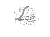
- FIG. 1 is a perspective view showing a configuration of a blood pressure measuring device according to an embodiment of the present invention.
- FIG. 2 is a perspective view showing the configuration of the blood pressure measuring device.
- FIG. 3 is a side view showing the configuration of the blood pressure measuring device.
- FIG. 4 is a side view showing the configuration of the blood pressure measuring device when worn on the wrist.
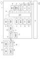
- FIG. 5 is a block diagram showing the configuration of the blood pressure measuring device.
- FIG. 6 is a cross-sectional view showing the configuration of a main part of the blood pressure measuring device.
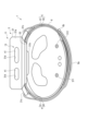
- FIG. 7 is a plan view showing the main configuration of the blood pressure measuring device as viewed from the back side of the device body.
- FIG. 1 is a perspective view showing a configuration of a blood pressure measuring device according to an embodiment of the present invention.
- FIG. 2 is a perspective view showing the configuration of the blood pressure measuring device.
- FIG. 3 is a side view showing the configuration of the blood pressure measuring device.
- FIG. 4 is a side view showing
- FIG. 8 is a plan view showing the main configuration of the blood pressure measuring device from the rear side of the device body with some components omitted.
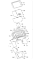
- FIG. 9 is an exploded perspective view showing the configuration of the main body of the device.
- FIG. 10 is an exploded perspective view showing the configuration of the main body of the device.
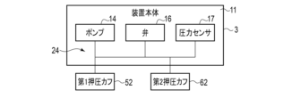
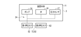
- FIG. 11 is a block diagram showing an example of a fluid circuit of the blood pressure measuring device.
- FIG. 12 is a perspective view illustrating a schematic configuration of a regulating member of the blood pressure measuring device of FIG.
- FIG. 13 is a perspective view illustrating a schematic configuration of a regulating member of the blood pressure measuring device.
- FIG. 14 is a plan view showing a main configuration of a blood pressure measuring device according to another embodiment of the present invention, viewed from the back side of the device main body.
- FIG. 15 is a side view showing the configuration of a blood pressure measurement device according to another embodiment of the present invention.
- FIG. 16 is a plan view showing a main configuration of a blood pressure measuring device according to another embodiment of the present invention, viewed from the back side of the device body.
- FIG. 17 is a block diagram showing an example of a fluid circuit of the blood pressure measuring device.
- FIG. 18 is a block diagram showing an example of a fluid circuit of the blood pressure measuring device.
- FIG. 19 is a cross-sectional view that illustrates a schematic configuration of a restriction member of a blood pressure measuring device according to another embodiment of the present invention.
- FIG. 1 is a perspective view showing the configuration of a blood pressure measuring device 1 according to an embodiment of the present invention.
- FIG. 2 is a perspective view showing the configuration of the blood pressure measuring device 1 with the restricting member 7 exposed.
- FIG. 3 is a side view showing the configuration of the blood pressure measuring device 1
- FIG. 4 is a side view showing the configuration of the blood pressure measuring device 1 in a state where it is worn on the wrist 300.
- FIG. 5 is a block diagram showing the configuration of the blood pressure measuring device 1.
- FIG. 6 is a cross-sectional view showing the configuration of the device body 3, a part of the first cuff structure 4, and a part of the second cuff structure 5 of the blood pressure measuring device 1.
- FIG. 1 is a perspective view showing the configuration of a blood pressure measuring device 1 according to an embodiment of the present invention.
- FIG. 2 is a perspective view showing the configuration of the blood pressure measuring device 1 with the restricting member 7 exposed.
- FIG. 3 is a side view showing the configuration of the blood
- FIG. 7 is a plan view showing the configuration of the device body 3, a part of the first cuff structure 4, and a part of the second cuff structure 5 of the blood pressure measuring device 1
- FIG. 8 is a plan view showing the configuration of the device body 3, a part of the first cuff structure 4, and a part of the second cuff structure 5 of the blood pressure measuring device 1 with the cuff cover 33 omitted.
- FIG. 9 is an exploded perspective view of the device main body 3 from above
- FIG. 10 is an exploded perspective view of the device main body 3 from below.
- FIG. 11 is a block diagram showing an example of a fluid circuit 24 of the blood pressure measuring device 1.
- FIG. 12 and FIG. 13 are perspective views showing a schematic configuration of the regulating member 7 of the blood pressure measuring device 1.
- the blood pressure measuring device 1 includes, for example, a device main body 3, a first cuff structure (first cuff) 4, a second cuff structure 5 (second cuff), a band 6, and a restricting member 7.
- the first cuff structure 4 and the second cuff structure 5 extend from the device main body 3 in the direction in which the device main body 3 faces each other, and the band 6 covers the first cuff structure 4 and the second cuff structure 5, and is formed so as to be fixed to the wrist 300, which is a living body.
- the blood pressure measuring device 1 restricts the relative movement of the first cuff structure 4 and/or the second cuff structure 5 and the band 6 in the width direction by the restricting member 7.
- the device main body 3 includes, for example, a housing 11, a display unit 12, an operation unit 13, a pump 14, an acceleration sensor 15, a valve 16, a pressure sensor 17, a battery 18, a communication unit 19, a biosensor 20, a charging circuit unit 21, a memory 22, a processor 23, a fluid circuit 24, and a substrate 25.
- the housing 11 is a case that houses the components of the device main body 3.
- the housing 11 houses, for example, a display unit 12, an operation unit 13, a pump 14, an acceleration sensor 15, a valve 16, a pressure sensor 17, a battery 18, a communication unit 19, a biosensor 20, a charging circuit unit 21, a memory 22, a processor 23, a fluid circuit 24, and a board 25.
- the housing 11 includes, for example, an outer case 31, a windshield 32 that covers the upper opening of the outer case 31, and a cuff cover 33 that is provided below the outer case 31.
- the outer case 31 is formed in a bottomed tubular shape, for example, a cylindrical shape, a rectangular tubular shape, or a polygonal tubular shape having a bottom.
- the outer case 31 is formed in a bottomed rectangular tubular shape.
- the outer case 31 has a rectangular tubular peripheral wall portion 31a, a bottom portion 31b provided on the peripheral wall portion 31a, and a pair of loop portions 31c provided on a pair of the four outer peripheral surfaces of the peripheral wall portion 31a.
- an opening 31d is formed in which a part of the operating portion 13 is disposed.
- the opening 31d is formed in one side of the peripheral wall portion 31a that is different from the two sides on which the pair of loop portions 31c are provided.
- two openings 31d are formed in one side of the peripheral wall portion 31a.
- the bottom 31b constitutes the back surface (bottom 31b) of the housing 11 (outer case 31).
- the bottom 31b protrudes in part so that it can come into contact with the wrist 300.
- the bottom 31b has a protrusion 31b1 formed by a rectangular protrusion at the center of the outer surface and a rectangular recess at the center of the inner surface of the bottom 31b.
- the bottom 31b also has a plurality of windows 31b2 in which the biosensors 20 are placed, and a plurality of holes 31b3 in which the connecting parts 73 and 83 described below are placed as members that fluidly connect the first cuff structure 4 and the second cuff structure 5 to the pump 14.
- the biosensor 20 is disposed on the inner surface of the protrusion 31b1.
- the protrusion 31b1 constitutes a sensor unit including at least one of the biosensor 20 and the charging terminal 214 disposed on the rear surface of the housing 11.
- the biosensor 20 and the charging terminal 214 disposed on the rear surface of the housing 11 means that some of the components constituting the biosensor 20 are exposed on the rear surface of the housing 11 or are disposed on the rear surface of the housing 11 via a member other than the first cuff structure 4 and the second cuff structure 5 (for example, the cover 31b5 described below).
- the window portion 31b2 is formed in the protruding portion 31b1.
- the window portion 31b2 is formed by a plurality of openings 31b4 formed in a plurality of places in the protruding portion 31b1 and a cover 31b5 having translucency, such as glass or a resin material, which covers the openings 31b4.
- the cover 31b5 covers, for example, the outer surface of the protruding portion 31b1.
- a plurality of holes 31b3 are formed between the protrusion 31b1 and each loop 31c in the bottom 31b.
- three holes 31b3 are formed between the protrusion 31b1 and one loop 31c, and three holes 31b3 are formed between the protrusion 31b1 and the other loop 31c.
- These three holes 31b3 are arranged in one direction, for example, in a direction perpendicular to the opposing direction of the pair of loops 31c.
- the bottom 31b which is the back surface of the housing 11, has three holes 31b3 at one end in one direction to which a part of the first cuff structure 4 is fixed, which are arranged at a position away from the protrusion 31b1, and three holes 31b3 at the other end in the one direction to which the other part of the first cuff structure 4 and the second cuff structure 5 are fixed, which are arranged away from the protrusion 31b1 in the other direction.
- the bottom 31b is formed with a slit-shaped ventilation hole 31b6 that is long in one direction, and the bottom 31b is provided with a waterproof and moisture-permeable sheet 31b7 that covers the ventilation hole 31b6.
- the waterproof and moisture-permeable sheet 31b7 is formed to prevent water from entering the housing 11 from the outside through the ventilation hole 31b6 of the bottom 31b, and to allow ventilation between the inside of the housing 11 and the outside.
- the ventilation hole 31b6 and the waterproof and moisture-permeable sheet 31b7 are provided in a position that does not overlap with the first cuff structure 4 and the second cuff structure 5 fixed to the bottom 31b, i.e., in a position separated from the first cuff structure 4 and the second cuff structure 5.
- a flow path body 72 of the first compression cuff 52 of the first cuff structure 4 (described later) is provided adjacent to one side of the protruding portion 31b1
- a ventilation hole 31b6 and a waterproof moisture-permeable sheet 31b7 are provided adjacent to the other side of the protruding portion 31b1.
- the loop portion 31c is formed so that the band 6 can be passed through and the band 6 can be fixed or folded back.
- the loop portion 31c is a rectangular ring-shaped member with an opening that is long in one direction through which the band 6 can be inserted.
- the loop portion 31c is formed integrally with the outer surface of the outer case 31. One end of the band 6 is fixed to one of the pair of loop portions 31c, and the band 6 is folded back to the other loop portion 31c.
- the windshield 32 is a rectangular glass plate in this embodiment, with a shape similar to the outer peripheral edge of the outer case 31. Note that the windshield 32 is not limited to a glass plate, as long as it is made of a transparent or translucent material.
- the cuff cover 33 covers the bottom 31b of the outer case 31.
- the cuff cover 33 has a protrusion 31b1 on the bottom 31b arranged thereon, and an opening 33a is formed to expose the protrusion 31b1 to the outside.
- the cuff cover 33 is formed with a thickness and shape such that when the cuff cover 33 is fixed to the bottom 31b, the protrusion 31b1 protrudes from the main surface of the cuff cover 33 that faces the wrist 300.
- the cuff cover 33 has holes 33b in which screws are arranged at the four corners, and is removably fixed to the bottom 31b of the outer case 31 of the housing 11 with screws or the like.
- the cuff cover 33 covers the ends of the first cuff structure 4 and the second cuff structure 5 that are arranged on the bottom 31b, arranges the ends of the first cuff structure 4 and the second cuff structure 5 in the gap between the bottom 31b, and fixes the first cuff structure 4 and the second cuff structure 5 to the bottom 31b.
- the cuff cover 33 covers a part of the flow path body 72 and the connection part 73 of the first pressure cuff 52 described below, the flow path body 82 and three connection parts 83 of the sensing cuff 54, and the flow path body 92 and two connection parts 93 of the second pressure cuff 62.
- the cuff cover 33 fixes the first cuff structure 4 and the second cuff structure 5 by restricting the movement of the covered parts of the part of the first pressure cuff 52, the sensing cuff 54, and the second pressure cuff 62 in a direction away from the bottom 31b.
- the cuff cover 33 may also be configured to have a cushioning material between the first cuff structure 4 and the second cuff structure 5.
- the display unit 12 is disposed directly below the windshield 32.
- the display unit 12 is electrically connected to the processor 23.
- the display unit 12 is, for example, a liquid crystal display or an organic electroluminescence display.
- the display unit 12 is an OLED (Organic Light Emitting Diode).
- the display unit 12 displays various information including date and time, blood pressure values such as systolic and diastolic blood pressure, measurement results such as heart rate, and information such as the charging status and remaining capacity of the battery 18.
- the display unit 12 is, for example, formed to have the same shape as the windshield 32 or a shape slightly smaller than the windshield 32 in a planar view.
- the operation unit 13 is configured to allow commands to be input from the user.
- the operation unit 13 includes, for example, a plurality of buttons 41 provided on the housing 11, a sensor that detects the operation of the buttons 41, and a touch panel 43 provided on the display unit 12 or the windshield 32.
- the operation unit 13 converts commands into electrical signals when operated by the user.
- the sensor and touch panel 43 are electrically connected to the processor 23, and output electrical signals corresponding to the operations to the processor 23.
- the pump 14 is, for example, a piezoelectric pump.
- the pump 14 compresses, for example, air as a fluid, and supplies the compressed air via the fluid circuit 24 to an air bag 71 of a first pressure cuff 52 and an air bag 81 of a sensing cuff 54 of the first cuff structure 4, which will be described later, and an air bag 91 of a second pressure cuff 62 of the second cuff structure 5, which will be described later.
- the pump 14 is electrically connected to the processor 23.
- the acceleration sensor 15 is, for example, a three-axis acceleration sensor.
- the acceleration sensor 15 measures, for example, acceleration and outputs an analog signal.
- the acceleration sensor 15 is connected to the processor 23, for example, via an A/D conversion circuit.
- the valve 16 is, for example, an on-off valve.
- the valve 16 opens and closes the fluid circuit that connects the pump 14 to the first cuff structure 4 and/or the second cuff structure 5 in the fluid circuit 24, and/or the fluid circuit that connects the first cuff structure 4 to the outside (atmosphere).
- the valve 16 is electrically connected to the processor 23. For example, the valve 16 is opened and closed under the control of the processor 23.
- the valve 16 is a safety valve that releases air supplied to the first pressure cuff 52, the second pressure cuff 62, and the sensing cuff 54 of the first cuff structure 4, which will be described later, to the atmosphere.
- the valve 16 is switched to a closed state by being controlled by the processor 23, for example, when air is supplied to the first pressure cuff 52 and the sensing cuff 54 during blood pressure measurement.
- the valve 16 is also switched from a closed state to an open state by being controlled by the processor 23, when air is exhausted from the first pressure cuff 52 and the sensing cuff 54.
- the valve 16 may be formed so that the opening degree can be adjusted.
- the valve 16 may be provided on the fluid circuit 24, or may be provided integrally inside the housing of the pump 14.
- the pressure sensor 17 is provided, for example, in the fluid circuit 24.
- the pressure sensor 17 detects the pressure of the first pressure cuff 52 and/or the sensing cuff 54.
- the pressure sensor 17 detects the pressure of the sensing cuff 54.
- the pressure sensor 17 is electrically connected to the processor 23, for example, via an A/D conversion circuit, converts the detected pressure into an electrical signal, and outputs it to the processor 23.
- Battery 18 is, for example, a secondary battery such as a rechargeable lithium-ion battery. Battery 18 is electrically connected to processor 23. Battery 18 supplies power to processor 23. Battery 18 supplies driving power to each component of processor 23, as well as to display unit 12, operation unit 13, pump 14, acceleration sensor 15, valve 16, pressure sensor 17, communication unit 19, and biosensor 20 via processor 23.
- the communication unit 19 is configured to be capable of transmitting and receiving information wirelessly and/or wired to and from an external device.
- the communication unit 19 is, for example, a wireless communication module that complies with wireless communication standards.
- the communication unit 19 transmits, for example, information controlled by the processor 23 and information such as measured blood pressure values and pulse rate to an external device, and also receives programs for software updates from the external device and sends them to the control unit.
- the external device is, for example, an external terminal such as a smartphone, tablet terminal, personal computer, or smartwatch.
- the communication unit 19 and the external terminal may be directly connected or may be connected via a network.
- the communication unit 19 and the external terminal may be connected via a mobile communication network such as 4G or 5G, or a wireless communication line such as Wimax or Wi-Fi (registered trademark).
- the communication unit 19 and the external device may also be connected via a wireless communication means such as BLE (Bluetooth (registered trademark) Low Energy), NFC (Near Filed Communication), or infrared communication.
- the communication unit 19 may have, in addition to a wireless communication module, a general-purpose connector such as a micro USB (Universal Serial Bus) or a dedicated connector for the blood pressure measurement device 1, and may be connected to the external terminal directly or via a wired communication line such as a LAN (Local Area Network) connection by various cables such as a USB cable.
- a general-purpose connector such as a micro USB (Universal Serial Bus) or a dedicated connector for the blood pressure measurement device 1
- a wired communication line such as a LAN (Local Area Network) connection by various cables such as a USB cable.
- the communication unit 19 may be configured to include multiple communication means such as a wireless antenna and a micro USB connector.
- the connector for wired communication may be a dedicated connector for the blood pressure measurement device 1.
- the biosensor 20 is a sensor that is configured to detect bioinformation by contacting or facing the wrist 300.
- the biosensor 20 converts the detected bioinformation into an electrical signal and outputs it to the processor 23.
- the biosensor 20 may be, for example, a sensor that measures physical quantities such as heart rate and body temperature, or a sensor that measures chemical values such as blood glucose level and blood oxygen concentration.
- the biosensor 20 includes, for example, a PPG sensor 20a, an SpO2 sensor 20b, and an ECG sensor 20c.
- the PPG sensor 20a measures the heart rate by photoplethysmography.
- the PPG sensor 20a includes a first LED 20d, a second LED 20e, and a first PD (Photodiode) 20f.
- the SpO2 sensor 20b measures saturation (percutaneous arterial blood oxygen saturation).
- the SpO2 sensor 20b includes a second LED 20e and a second PD 20g.
- the PPG sensor 20a and the SpO2 sensor 20b share the second LED 20e.
- the ECG sensor 20c measures the flow of electricity in the heart and obtains an electrocardiogram waveform.
- the ECG sensor 20c has a pair of electrocardiogram electrodes 20c1.
- the charging circuit unit 21 includes, for example, an antenna unit 211, a power receiving unit 212, a charging unit 213, and a charging terminal 214.
- the charging circuit unit 21 charges the battery 18 by wire power supply and/or wireless power supply.
- the charging circuit unit 21 receives transmission power transmitted from the antenna unit 103 of the power transmission device 100 provided externally via the antenna unit 211, and charges the battery 18.
- the charging circuit unit 21 receives transmission power transmitted from the power transmission terminal 104 of the power transmission device 100 provided externally via the charging terminal 214, and charges the battery 18. That is, the charging circuit unit 21 selectively uses the antenna unit 211 and the charging terminal 214 to receive power from the power transmission device 100, and charges the battery 18.
- the charging circuit section 21 may be configured to allow both wire and wireless power supply, or may be configured to allow only one of wire and wireless power supply.
- the antenna unit 211 receives the transmitted power from the antenna unit 103 of the power transmitting device 100.
- the antenna unit 211 is, for example, a receiving coil serving as a receiving resonant circuit.
- the antenna unit 211 supplies the received power to the receiving unit 212.
- the receiving surface of the antenna unit 211 is formed in a flat shape.
- the antenna unit 211 is, for example, disposed within the housing 11. As a specific example, the antenna unit 211 is disposed within the housing 11, adjacent to the display unit 12, on the opposite side of the windshield 32 of the display unit 12.
- the antenna unit 211 includes, for example, a resonant capacitor, and constitutes a receiving resonant circuit.
- the power receiving unit 212 rectifies the power received by the antenna unit 211 or the charging terminal 214 and supplies it to the charging unit 213.
- the power receiving unit 212 rectifies the received power supplied from the antenna unit 211 and converts it from AC to DC.
- the power receiving unit 212 includes a rectifier circuit and a control circuit, and the control circuit controls the operation of the rectifier circuit and outputs the rectified DC power to the charging unit 213.
- the charging unit 213 supplies the power supplied from the power receiving unit 212 to the battery 18 as charging power.
- the charging unit 213 converts the power supplied from the power receiving unit 212 into a predetermined current value and voltage value and supplies it to the battery 18.
- the charging unit 213 may have a circuit that outputs the charging state of the battery 18 to the power receiving unit 212 and/or the processor 23.
- the charging terminal 214 has, for example, a pair of terminals 214a, and receives transmitted power from the power transmission terminal 104 of the power transmission device 100 via this pair of terminals 214a.
- the memory 22 includes, for example, a RAM (Random Access Memory) and a ROM (Read Only Memory).
- the memory 22 stores various data.
- the memory 22 pre-stores, in a changeable manner, various program data such as programs and applications for controlling the entire blood pressure measuring device 1 and the pump 14, setting data for setting various functions of the blood pressure measuring device 1, calculation data for calculating a blood pressure value from the pressure measured by the pressure sensor 17, and calculation data for calculating bioinformation such as heart rate, saturation, and electrocardiogram waveform from information measured by the biosensor 20.
- the processor 23 controls the operation of the entire blood pressure measuring device 1, as well as the operation of the pump 14 and the valve 16, based on the programs stored in the memory 22, and executes predetermined operations (functions). The processor 23 also executes predetermined calculations, analyses, processing, etc., according to the loaded programs.
- the processor 23 is a calculation device such as a CPU.
- the processor 23 may include, for example, a main CPU and a sub-CPU.
- the processor 23 also displays the status and results of the various executed operations and the calculations, analyses, processing, etc., on the display unit 12 by means of a program or application.
- the fluid circuit 24 fluidly connects at least two of the pump 14, valve 16, pressure sensor 17, first cuff structure 4, and second cuff structure 5, which are provided in the housing 11.
- the fluid circuit 24 may include components such as a tube or flow path plate 24a that forms a flow path for the fluid supplied from the pump 14 to the first cuff structure 4, a single or multiple orifices 24b that are flow resistances that control the supply amount and pressure of the fluid supplied to the first cuff structure 4 and/or the second cuff structure 5, and a check valve that controls the flow direction of the fluid.
- the flow path plate 24a is formed by joining multiple plates made of a resin material or a metal material to a sheet or double-sided tape that is arranged between adjacent plates and has slits that serve as flow paths.
- the multiple orifices 24b may be provided in the flow path plate 24a, or may be provided in a part of the first cuff structure 4 or the second cuff structure 5.
- the board 25 includes, for example, a control board 25a, a sensor main board 25b, and a sensor sub-board 25c.
- the control board 25a is equipped with, for example, the acceleration sensor 15, the valve 16, the pressure sensor 17, the communication unit 19, the circuit configuration of the charging circuit unit 21, the memory 22, and the processor 23.
- the first LED 20d, second LED 20e, first PD 20f, and second PD 20g used in the PPG sensor 20a and SpO2 sensor 20b are mounted on the sensor main board 25b.
- Various circuits and electronic components for configuring the PPG sensor 20a, the SpO2 sensor 20b, and the ECG sensor 20c are mounted on the sensor sub-board 25c.
- the control board 25a, the sensor main board 25b, and the sensor sub-board 25c are electrically connected.
- the first cuff structure 4 includes a first curler 51, a first pressure cuff 52, a back plate 53, and a sensing cuff 54.
- the first cuff structure 4 includes, for example, a first curler 51, a first pressure cuff 52, a back plate 53, and a sensing cuff 54.
- the first cuff structure 4 is configured by sequentially stacking the first curler 51, the first pressure cuff 52, the back plate 53, and the sensing cuff 54 toward the wrist 300.
- the first cuff structure 4 may be configured without the first curler 51 and/or the back plate 53.
- the first curler 51 is fixed, for example, to the bottom 31b, one end of which is provided on the wrist 300 side of the housing 11.
- the first curler 51 is formed in a band shape that curves to follow the circumferential direction of the wrist 300.
- the first curler 51 is made of a resin material.
- the first curler 51 is formed of a low-hardness material that is flexible and has shape retention.
- flexibility means that the shape of the first curler 51 deforms in the radial direction when an external force is applied to the first curler 51 from the band 6.
- Shape retention means that the first curler 51 can maintain a pre-formed shape when no external force is applied.
- the first curler 51 is formed of a resin material that is not compressively deformed or does not omit compressive deformation, but has a hardness that allows elastic deformation such as bending deformation that changes the shape, especially the curvature of the curved part. Therefore, the first curler 51 is formed to be elastically deformable so that it bends and deforms when an external force is applied, and the internal space in which the wrist 300 is placed becomes larger or smaller according to the shape of the wrist on which it is worn.
- the first curler 51 is formed from a thermoplastic polyurethane resin (hereinafter referred to as TPU) or a polypropylene resin.
- the first curler 51 is fixed to the housing 11.
- the first curler 51 is formed to a length that faces at least one of the two arteries 311, 312 when the blood pressure measuring device 1 is worn on the wrist 300 that has the longest circumference among the users who are expected to wear the device.
- the first curler 51 is formed to a length that faces the two arteries 311, 312 when the blood pressure measuring device 1 is worn on the wrist 300 that has the longest circumference among the users who are expected to wear the device.
- the first curler 51 is set to a length that does not make the other end come into contact with the device main body 3 when the blood pressure measuring device 1 is worn on the wrist 300 that has the shortest circumference among the users who are expected to wear the device.
- the portion of the first curler 51 that extends from the housing 11 of the device main body 3 is curved with a predetermined radius of curvature so as to follow the shape of one of the sides of the wrist 300 and the palm side of the wrist 300.
- the first pressure cuff 52 is fixed to the inner surface of the first curler 51 by double-sided tape, adhesive, heat welding, or the like.
- the first pressure cuff 52 is fluidly connected to the pump 14 via the fluid circuit 24.
- One main surface of the first pressure cuff 52 is fixed to the inner surface of the first curler 51.
- the first pressure cuff 52 comprises, for example, one or more air bags 71, a flow path body 72 provided at the end of the air bag 71, and a connection part 73 such as a nipple provided on the flow path body 72 and connected to the fluid circuit 24.
- the air bag 71 is a bag-like structure, and in this embodiment, the blood pressure measuring device 1 is configured to use air via the pump 14, so an air bag will be used for the explanation, but if a fluid other than air is used, the bag-like structure may be a fluid bag that expands with the fluid.
- the air bag 71 is formed into a rectangular bag shape that is long in one direction.
- the air bag 71 is formed into a bag shape by heat welding or the like of multiple sheet members.
- the multiple air bags 71 are stacked and integrally formed by welding or the like, and are fluidly continuous.
- the sheet member forming the air bag 71 is formed, for example, from a thermoplastic elastomer.
- an example of the thermoplastic elastomer is TPU.
- the flow path body 72 is, for example, integrally provided on a portion of one edge in the longitudinal direction of the air bag 71.
- the flow path body 72 is formed by a portion of two of the multiple sheet members that form the air bag 71.
- the flow path body 72 is formed in a shape that is elongated in one direction with a width smaller than the width of the air bag 71 in the short direction.
- a connection portion 73 is integrally provided at the tip of the flow path body 72.
- the flow path body 72 is connected to the fluid circuit 24 via the connection portion 73, and forms a flow path between the fluid circuit 24 and the air bag 71.
- the thickness of the flow path body 72 when inflated is smaller than the thickness of the air bag 71 when inflated.
- connection part 73 is provided.
- the one connection part 73 is connected to the fluid circuit 24 via one hole part 31b3 formed in the bottom part 31b.
- the flow path body 72 extends from one end side to the other end side of the bottom 31b in the opposing direction of the pair of loop portions 31c adjacent to the protrusion 31b1 to avoid the protrusion 31b1 formed on the bottom 31b, and the connection portion 73 is connected to one of the three holes 31b3 formed at the end of the bottom 31b on the side where the second cuff structure 5 protrudes.
- the back plate 53 is fixed to the surface of the first pressure cuff 52 facing the wrist 300 with double-sided tape, adhesive, or the like.
- the back plate 53 is formed from a resin material.
- the back plate 53 is formed, for example, in the shape of a rectangular plate that is long in one direction. Note that the back plate 53 may be formed, for example, in a divided configuration, that is, formed by arranging multiple rectangular pieces in one direction.
- the back plate 53 has shape-following properties.
- shape conformability refers to the ability of the back plate 53 to deform so as to follow the shape of the contacted portion of the wrist 300 on which it is placed
- the contacted portion of the wrist 300 refers to the area of the wrist 300 that comes into contact with the back plate 53, and contact here includes both direct contact with the back plate 53 and indirect contact via the sensing cuff 54 of the back plate 53.
- the sensing cuff 54 is fixed to the main surface of the back plate 53 on the wrist side.
- the sensing cuff 54 contacts the area of the wrist 300 where the arteries 311, 312 are located directly, or indirectly via a cover or the like.
- the sensing cuff 54 is formed in a rectangular shape that is long in one direction.
- the sensing cuff 54 may be configured to contact the area of the wrist 300 where one of the arteries 311, 312 is located.
- the sensing cuff 54 is the same as or smaller than the first pressure cuff 52 in the longitudinal direction.
- the sensing cuff 54 is also the same as or smaller than the first pressure cuff 52 in the transverse direction.
- the sensing cuff 54 is the same shape as the back plate 53, or smaller than the back plate 53, or larger than the back plate 53 in the longitudinal and width directions of the back plate 53.
- the sensing cuff 54 expands, it presses the area where the artery is located on the palm side of the wrist.
- the sensing cuff 54 is pressed against the living body via the back plate 53 by the inflated first pressure cuff 52.
- the sensing cuff 54 includes an air bag 81, a flow path body 82 that is fluidly connected to the air bag 81, and a connection portion 83 such as a nipple that is provided on the flow path body 82.
- the air bag 81 and the flow path body 82 are formed into a bag shape by thermal welding or the like of multiple sheet members.
- the sheet members that form the air bag 81 and the flow path body 82 are formed, for example, from a thermoplastic elastomer.
- the thermoplastic elastomer is, for example, TPU.
- the air bag 81 is a bag-like structure.
- the blood pressure measuring device 1 is configured to use air via the pump 14, so an air bag will be used for the explanation, but if a fluid other than air is used, the bag-like structure may be a fluid bag that expands with the fluid.
- the air bag 81 is configured in a rectangular shape that is long in one direction.
- the flow path body 82 is, for example, integrally provided on a part of one edge in the longitudinal direction of the air bag 81.
- the flow path body 82 is formed by a part of two of the multiple sheet members that form the air bag 81.
- the flow path body 82 is formed in a shape that is elongated in one direction with a width smaller than the width of the air bag 81 in the short direction.
- a connection part 83 is integrally provided at the tip of the flow path body 82.
- the flow path body 82 is connected to the fluid circuit 24 via the connection part 83, and forms a flow path between the fluid circuit 24 and the air bag 81.
- the thickness of the flow path body 82 when inflated is smaller than the thickness of the air bag 81 when inflated.
- connection parts 83 are provided.
- the three connection parts 83 are connected to three holes 31b3 formed at the end of the bottom part 31b on the side from which the first cuff structure 4 protrudes.
- the three connection parts 83 are connected to the fluid circuit 24.
- the second cuff structure 5 includes a second curler 61 and a second pressure cuff 62.
- the second cuff structure 5 is configured by sequentially stacking the second curler 61 and the second pressure cuff 62 toward the wrist 300.
- the second curler 61 is fixed, for example, to the bottom 31b, one end of which is provided on the wrist 300 side of the housing 11.
- the second curler 61 is formed in a band shape that curves to follow the circumferential direction of the wrist 300.
- the second curler 61 is made of a resin material.
- the second curler 61 is formed of a low-hardness material that is flexible and has shape retention.
- flexibility means that the shape of the second curler 61 deforms in the radial direction when an external force is applied to the second curler 61 from the band 6.
- Shape retention means that the second curler 61 can maintain a pre-formed shape when no external force is applied.
- the second curler 61 is formed of a resin material with a hardness that does not undergo compressive deformation or does not omit compressive deformation, but allows elastic deformation such as bending deformation that changes the shape, especially the curvature of the curved part. Therefore, the second curler 61 is formed to be elastically deformable so that it bends and deforms when an external force is applied, and the internal space in which the wrist 300 is placed becomes larger or smaller according to the shape of the wrist on which it is worn.
- the second curler 61 is formed from a thermoplastic polyurethane resin (hereinafter referred to as TPU) or a polypropylene resin.
- the second curler 61 is fixed to the housing 11.
- the second curler 61 is formed to a length that faces at least one of the two arteries 311, 312 when the blood pressure measuring device 1 is worn on the wrist 300 with the longest circumference among the users who are expected to wear it, and the end side overlaps with the first cuff structure 4.
- one of the two arteries 311, 312 is the radial artery 311, and the other is the ulnar artery 312.
- the second curler 61 is formed to a length that faces the two arteries 311, 312 when the blood pressure measuring device 1 is worn on the wrist 300 with the longest circumference among the users who are expected to wear it.
- the second curler 61 is set to a length that does not make the other end contact with the device main body 3 when the blood pressure measuring device 1 is worn on the wrist 300 with the shortest circumference among the users who are expected to wear it.
- the portion of the second curler 61 that extends from the housing 11 of the device main body 3 is curved with a predetermined radius of curvature so as to follow the shape of one of the sides of the wrist 300 and the palm side of the wrist 300.
- the second pressure cuff 62 is fixed to the inner peripheral surface of the second curler 61 by double-sided tape, adhesive, heat welding, or the like.
- the second pressure cuff 62 is fluidly connected to the pump 14 via the fluid circuit 24.
- One main surface of the second pressure cuff 62 is fixed to the inner surface of the second curler 61.
- the second pressure cuff 62 inflates, it presses against the opposing wrist 300 and presses the overlapping first cuff structure 4 toward the wrist 300.
- the thickness of the second pressure cuff 62 when inflated is the same as or greater than the thickness of the first pressure cuff 52 when inflated.
- the second pressure cuff 62 comprises, for example, one or more air bags 91, a flow path body 92 provided at the end of the air bag 91, and a connection part 93 such as a nipple provided on the flow path body 92 and connected to the fluid circuit 24.
- the air bag 91 is a bag-like structure, and in this embodiment, the blood pressure measuring device 1 is configured to use air via the pump 14, so an air bag will be used for the explanation, but if a fluid other than air is used, the bag-like structure may be a fluid bag that expands with the fluid.
- the air bag 91 is formed into a rectangular bag shape that is long in one direction.
- the air bag 91 is formed into a bag shape by heat welding or the like of multiple sheet members.
- the multiple air bags 91 are stacked and integrally formed by welding or the like, and are fluidly continuous.
- the sheet member forming the air bag 91 is formed, for example, from a thermoplastic elastomer.
- an example of the thermoplastic elastomer is TPU.
- the flow path body 92 is, for example, integrally provided on a part of one edge in the longitudinal direction of the air bag 91.
- the flow path body 92 is formed by a part of two of the multiple sheet members that form the air bag 91.
- the flow path body 92 is formed in a shape that is elongated in one direction with a width smaller than the width of the air bag 91 in the short direction.
- a connection portion 93 is integrally provided at the tip of the flow path body 92.
- the flow path body 92 is connected to the fluid circuit 24 via the connection portion 93, and forms a flow path between the fluid circuit 24 and the air bag 71.
- the thickness of the flow path body 92 when inflated is smaller than the thickness of the air bag 91 when inflated.
- connection parts 93 are provided.
- the two connection parts 93 are connected to the fluid circuit 24 via two holes 31b3 formed in the bottom part 31b.
- connection portion 93 is connected to two of the three holes 31b3 formed at the end of the bottom portion 31b on the side from which the second cuff structure 5 protrudes.
- the first pressure cuff 52 and the second pressure cuff 62 of the first cuff structure 4 and the second cuff structure 5 configured in this manner are formed to a length such that, when the blood pressure measuring device 1 is attached to the wrist 300 with the maximum circumference, the inflated portion of the air bag 71 of the first pressure cuff 52 covers at least one of the two arteries 311, 312, and the air bag 91 of the second pressure cuff 62 can overlap the air bag 71.
- the air bag 91 of the second pressure cuff 62 is formed to a length such that, when the blood pressure measuring device 1 is attached to the wrist 300 with the maximum circumference and overlaps the air bag 71 of the first pressure cuff 52, the end edge of the air bag 91 on the opposite side to the flow path body 92 does not overlap the air bag 71 of the first pressure cuff 52 on the artery covered by the air bag 71 of the first pressure cuff 52.
- the inflated portion of the air bag 91 of the second pressure cuff 62 is set to a length that overlaps with the air bag 71 of the first pressure cuff 52 on the artery covered by the air bag 71 of the first pressure cuff 52.
- the band 6 is formed in a band shape on the outer periphery of the first cuff structure 4 and the second cuff structure 5, opposite the wrist 300.
- the band 6 is not fixed to the first cuff structure 4 and the second cuff structure 5.
- One end of the band 6 is fixed to one of the loop portions 31c.
- the band 6 also has a pair of hook-and-loop fasteners 6a, one of which has a hook and the other a loop, which engage with each other to fix the band 6, with its end inserted in the other loop portion 31c.
- the band 6 also has a knob 6b at the other end to make it easier for the user to grasp.
- the band 6 is fixed to the loop portion 31c formed on the side from which the second cuff structure 5 extends, inserted into the loop portion 31c formed on the side from which the first cuff structure 4 extends, and then folded back.
- the band 6 has a length that allows it to be inserted into the loop portion 31c provided on the outer case 31 when the blood pressure measuring device 1 is attached to the wrist 300 having the maximum circumference expected to be attached.
- the hook-and-loop fastener 6a is provided on the band 6 at a length and position that allows the band 6 to be folded back and fastened on the wrist 300 having the maximum and minimum circumferences expected to be attached.
- the end of the band 6 folded back at the loop portion 31c is pulled in a direction away from the loop portion 31c, so that the blood pressure measuring device 1 is attached to the wrist 300 with the first cuff structure 4 and the second cuff structure 5 wrapped around the wrist 300 as shown in FIG. 3.
- the band 6 With the hook-and-loop fastener 6a, the movement of the first pressure cuff 52 and the second pressure cuff 62 to expand outward on the side opposite the wrist when inflated is restricted, so that the first pressure cuff 52 and the second pressure cuff 62 can press against the wrist. This makes it possible to measure blood pressure using the known oscillometric method.
- the restricting member 7 restricts the relative movement in the width direction between the first cuff structure 4 and/or the second cuff structure 5 and the band 6.
- the width direction is the direction perpendicular to the direction in which the band 6 is wrapped around the wrist 300, in other words, the direction perpendicular to the longitudinal direction of the first cuff structure 4, the second cuff structure 5, and the band 6.
- the blood pressure measuring device 1 has a first cuff structure 4 and a second cuff structure 5, and the band 6 is not fixed to the first cuff structure 4 and the second cuff structure 5. Therefore, an example is described in which the restricting member 7 restricts the relative movement of the first cuff structure 4, the second cuff structure 5, and the band 6 in the width direction.
- the regulating member 7 includes a sheet 7a, a first hook-and-loop fastener 7b, a second hook-and-loop fastener 7c, a first regulating portion 7d, and a second regulating portion 7e.
- the sheet 7a is formed in a plate shape that is long in one direction.
- the width of the sheet 7a is smaller than the widths of the first cuff structure 4, the second cuff structure 5, and the band 6.
- the sheet 7a is formed, for example, from a resin material.
- One end of the sheet 7a is fixed to the outer surface of the end of the first cuff structure 4 on the device body 3 side.
- the sheet 7a is fixed to the outer surface of a portion of the first curler 51 of the first cuff structure 4 adjacent to the device body 3.
- the sheet 7a and the first cuff structure 4 are fixed, for example, by welding, adhesion with double-sided tape or adhesive, or joining with a hook-and-loop fastener.
- the sheet 7a is formed so that it can be separated from the first cuff structure 4, with the one end fixed to the first cuff structure 4 as a base point.
- the first hook-and-loop fastener 7b is provided on the outer surface of the end (tip) of the first cuff structure 4 opposite the device body 3.
- the second hook-and-loop fastener 7c is provided, for example, on the inner surface of the end (tip) of the sheet 7a opposite the device body 3 side, which faces the wrist 300.
- the first hook-and-loop fastener 7b and the second hook-and-loop fastener 7c are formed so that they can be joined.
- the first hook-and-loop fastener 7b and the second hook-and-loop fastener 7c function as fixing members that fix the sheet 7a and the first cuff structure 4.
- the fixing member is not limited to hook-and-loop fasteners, and other examples include magnetic sheets, snap fits, etc.
- the first restricting portion 7d restricts the relative movement of the first cuff structure 4 and the band 6 in the width direction, and allows the relative movement of the first cuff structure 4 and the band 6 in the longitudinal direction without restricting it. Also, for example, the first restricting portion 7d restricts the relative movement of the first cuff structure 4 and the band 6 in the direction perpendicular to the width direction and longitudinal direction of the first cuff structure 4 and the band 6, that is, in the direction along the opposing direction of the first cuff structure 4 and the band 6, in the direction in which the first cuff structure 4 and the band 6 move apart. The first restricting portion 7d restricts the relative movement of the first cuff structure 4 and the band 6 in the width direction and the direction in which they move apart by engaging with the sheet 7a fixed to the first cuff structure 4.
- the first restricting portion 7d is formed in an annular shape and is formed so that the sheet 7a can be inserted therein.
- the first restricting portion 7d is provided on the inner surface of the band 6.
- the first restricting portion 7d is formed by fixing a sheet-like member in an annular shape to the inner surface of the band 6.
- the second regulating portion 7e regulates the relative movement of the first cuff structure 4 and the second cuff structure 5 in the width direction, and allows the relative movement of the first cuff structure 4 and the band 6 in the longitudinal direction without regulating it. Also, for example, the second regulating portion 7e regulates the relative movement of the first cuff structure 4 and the second cuff structure 5 in the direction perpendicular to the width direction and longitudinal direction of the first cuff structure 4 and the second cuff structure 5, i.e., in the direction along the opposing direction of the first cuff structure 4 and the second cuff structure 5.
- the second regulating portion 7e regulates the relative movement of the first cuff structure 4 and the second cuff structure 5 in the width direction and the direction in which they separate by engaging with the sheet 7a fixed to the first cuff structure 4. Therefore, the second restricting portion 7e, together with the sheet 7a and the first restricting portion 7d, restricts movement of the first cuff structure 4, the second cuff structure 5, and the band 6 in the width direction, and in the direction in which the first cuff structure 4 and the second cuff structure 5 face the band 6 and move away from each other.
- the second restricting portion 7e is formed in an annular shape and is formed so that the sheet 7a can be inserted therein.
- the second restricting portion 7e is provided on the inner surface of the band 6.
- the second restricting portion 7e is formed by fixing a sheet-like member in an annular shape to the inner surface of the band 6.
- the length of the first restricting portion 7d and the second restricting portion 7e in the longitudinal direction of the band 6 and the second cuff structure 5 can be appropriately set based on the ease of relative movement in the width direction of the first cuff structure 4, the second cuff structure 5, and the band 6, and the stability of the posture of the first cuff structure 4, the second cuff structure 5, and the band 6. That is, by increasing the length of the first restricting portion 7d and the second restricting portion 7e in the longitudinal direction of the band 6 and the second cuff structure 5, the length of contact with the sheet 7a in the width direction can be secured, so that the sheet 7a can be stably held in the width direction.
- the sheet 7a can be easily inserted and the frictional force in the sliding movement with the sheet 7a can be reduced, so that the first cuff structure 4, the second cuff structure 5, and the band 6 can easily move relatively in the longitudinal direction in a stable manner.
- the width of the opening into which the sheet 7a of the first restricting portion 7d and the second restricting portion 7e is inserted is larger than the width of the sheet 7a.
- the width of the opening into which the sheet 7a of the first restricting portion 7d and the second restricting portion 7e is inserted can be set appropriately based on the ease of inserting the sheet 7a, the ease of relative movement in the width direction of the first cuff structure 4, the second cuff structure 5, and the band 6, the stability of the posture of the first cuff structure 4, the second cuff structure 5, and the band 6, etc.
- the length and width of the first restricting portion 7d and the second restricting portion 7e can be set according to the desired function, etc.
- the first restricting portion 7d and the second restricting portion 7e may have the same shape, or the first restricting portion 7d and the second restricting portion 7e may have different shapes, such as by making one of the first restricting portion 7d and the second restricting portion 7e longer and/or wider than the other restricting portion.
- the length of the sheet 7a, the position of the pair of hook-and-loop fasteners 7b, 7c, the position of the first restricting portion 7d, and the position of the second restricting portion 7e are set to a length and/or position such that when the blood pressure measuring device 1 is attached to the wrist 300 having the minimum and maximum circumferences expected to be attached, and when the band 6 is wrapped around the wrist 300 having the minimum and maximum circumferences expected to be attached, the sheet 7a can be inserted into the first restricting portion 7d and the second restricting portion 7e, and the sheet 7a and the first cuff structure 4 can be fixed with the hook-and-loop fasteners 7b, 7c.
- the length of the sheet 7a, the position of the pair of hook-and-loop fasteners 7b, 7c, the position of the first restricting portion 7d, and the position of the second restricting portion 7e are set to a length and/or position such that when the blood pressure measuring device 1 is attached to the wrist 300 having the minimum and maximum circumferences expected to be attached, the first cuff structure 4 and the sheet 7a joined by the pair of hook-and-loop fasteners 7b, 7c do not interfere with the second restricting portion 7e and the first cuff structure 4 in the longitudinal direction.
- the first restriction portion 7d is positioned so as not to come into contact with the end of the second cuff structure 5 when the blood pressure measurement device 1 is worn on the wrist 300 having the minimum and maximum circumferences expected for wearing.
- the restricting member 7 can move the first cuff structure 4 and the second cuff structure 5 to a position suitable for attachment to the wrist 300. Furthermore, the restricting member 7 does not interfere with the second restricting portion 7e provided on the band 6 and the second cuff structure 5, and does not restrict the relative movement of the second cuff structure 5 and the band 6 in the wrapping direction around the wrist 300.
- such a restricting member 7 releases the connection of the hook-and-loop fasteners 7b and 7c provided on the first cuff structure 4 and the sheet 7a, and inserts the sheet 7a into the first restricting portion 7d and the second restricting portion 7e while separating the first cuff structure 4 from the sheet 7a. Then, the hook-and-loop fasteners 7c of the sheet 7a inserted into the first restricting portion 7d and the second restricting portion 7e are joined to the hook-and-loop fasteners 7b of the first cuff structure 4. In this way, the restricting member 7 restricts the relative movement in the width direction while allowing the relative movement in the longitudinal direction of the first cuff structure 4, the second cuff structure 5, and the band 6.
- the first pressing cuff 52 is connected to the pump 14, for example, via the flow path plate 24a.
- the first pressing cuff 52 and the pump 14 are connected to the valve 16, for example, via the flow path plate 24a.
- the first pressing cuff 52 is connected to the second pressing cuff 62, for example, via the flow path plate 24a.
- the first pressing cuff 52 is connected to the sensing cuff 54, for example, via the flow path plate 24a and an orifice 24b provided in the flow path plate 24a.
- the sensing cuff 54 is connected to the pressure sensor 17, for example, via the flow path plate 24a.
- the sensing cuff 54 is connected to the atmosphere, for example, via the flow path plate 24a and an orifice 24b provided in the flow path plate 24a.
- the orifice 24b between the first pressure cuff 52 and the sensing cuff 54, and the orifice 24b between the sensing cuff 54 and the atmosphere are set to a flow resistance that results in a desired pressure difference between the first pressure cuff 52 and the sensing cuff 54.
- the power transmitting device 100 includes a power source 101, a power transmitting unit 102, an antenna unit 103, and a power transmitting terminal 104.
- the power transmitting device 100 may include either the antenna unit 103 or the power transmitting terminal 104.
- the power source 101 is, for example, an AC adapter connected to a commercial power source or the like. The power source 101 converts AC power input from the commercial power source into DC power and supplies the DC power to the power transmitting unit 102.
- the power transmission unit 102 generates AC power as transmission power from the DC power supplied from the power source 101, and supplies it to the antenna unit 103.
- the power transmission unit 102 generates AC power with a frequency that is the same or approximately the same as the resonant frequency of the power transmission resonant circuit of the antenna unit 103, for example.
- the antenna unit 103 is, for example, a power transmission coil serving as a power transmission resonant circuit.
- the power transmission surface of the antenna unit 103 is formed in a planar shape.
- the antenna unit 103 transmits power to the antenna unit 211 of the device main body 3.
- the antenna unit 103 includes, for example, a resonant capacitor, and constitutes a power transmission resonant circuit.
- the power transmission terminal 104 comes into contact with the charging terminal 214 provided on the device body 3 and is configured so that it can be fixed to the charging terminal 214.
- the blood pressure measuring device 1 configured in this manner can restrict the widthwise movement of the first cuff structure 4 and the band 6 by the restricting member 7, and can also restrict the widthwise movement of the first cuff structure 4 and the second cuff structure 5. Therefore, the blood pressure measuring device 1 can prevent the first cuff structure 4, the second cuff structure 5, and the band 6 from shifting in the widthwise position when the device is attached to the wrist 300 and when the first cuff structure 4 and the second cuff structure 5 are inflated. Therefore, the band 6 can stably press the first cuff structure 4 and the second cuff structure 5 toward the wrist 300, so that the first cuff structure 4 and the second cuff structure 5 can suitably compress the wrist 300. Therefore, the blood pressure measuring device 1 has good blood pressure measurement accuracy.
- the restricting member 7 does not restrict the longitudinal movement of the first cuff structure 4, the second cuff structure 5, and the band 6, by wrapping the band 6 around the wrist 300, the first cuff structure 4 and the second cuff structure 5 also move in the longitudinal direction, and the first cuff structure 4 and the second cuff structure 5 can be wrapped around the wrist 300 in an appropriate manner.
- the restricting member 7 is arranged so that the first restricting portion 7d provided on the band 6 does not interfere with the second cuff structure 5, and does not hinder the relative longitudinal movement of the first cuff structure 4, the second cuff structure 5, and the band 6. Therefore, the blood pressure measuring device 1 can easily adjust the relative positions of the first cuff structure 4, the second cuff structure 5, and the band 6.
- the blood pressure measuring device 1 also has a first cuff structure 4 and a second cuff structure 5 that are fluidly connected and extend from the device body 3 on both sides in one direction of the device body 3.
- the device body 3 also has a protrusion (sensor portion) 31b1 on the bottom 31b of the housing 11, which is the back side, at a position away from the first cuff structure 4 and the second cuff structure 5, for example, at the center of the bottom 31b, as a space for arranging at least one of the biosensor 20 and the charging terminal 214. This allows the first cuff structure 4 and the second cuff structure 5, and at least one of the biosensor 20 and the charging terminal 214 to be arranged on the back side of the device body 3.
- the first cuff structure 4 and the second cuff structure 5 are fluidly connected via a fluid circuit 24 including a flow path plate 24a.
- the first cuff structure 4 and the second cuff structure 5 may also be fluidly connected directly to the first pressure cuff 52 and the second pressure cuff 62. With this configuration, the first cuff structure 4 and the second cuff structure 5 can be fluidly continuous even if they are provided and fixed to the housing 11 apart in one direction.
- the air bag 71 of the first pressure cuff 52 covers the area in which at least one of the two arteries 311, 312 is present, and the air bag 91 of the second pressure cuff 62 can overlap at least a portion of the air bag 71 of the first pressure cuff 52.
- the wrist 300 can be pressed by the first pressure cuff 52 and the second pressure cuff 62, so that sufficient pressure force can be secured to compress the artery even if the air bag 71 of the first pressure cuff 52 and the air bag 91 of the second pressure cuff 62 are not disposed on the back surface of the device main body 3.
- the air bag 71 of the first pressure cuff 52 and the air bag 91 of the second pressure cuff 62 can overlap by a predetermined length. Furthermore, when the blood pressure measuring device 1 is worn on the wrist 300 with the minimum circumference, the first cuff structure 4 and the second cuff structure 5 are long enough not to come into contact with the device body 3. Furthermore, the first cuff structure 4 and the second cuff structure 5 are not directly joined to the band 6.
- the blood pressure measuring device 1 can suitably press the artery with the first pressure cuff 52 and the second pressure cuff 62 because the air bags 71, 91 of the first pressure cuff 52 and the second pressure cuff 62 overlap and inflate. Therefore, the blood pressure measuring device 1 can place the biosensor 20 on the back side of the device body 3, and can perform accurate blood pressure measurement even if the air bags 71, 91 of the first pressure cuff 52 and the second pressure cuff 62 are not placed on the back side of the device body 3.
- the housing 11 has an air vent 31b6 on the bottom 31b, covered with a waterproof/breathable sheet 31b7, which allows ventilation inside the housing 11.
- the air vent 31b6 is located away from the first cuff structure 4 and the second cuff structure 5 at a location other than the protruding portion 31b1 of the bottom 31b, which prevents the air vent 31b6 from being blocked by the first cuff structure 4 and the second cuff structure 5.
- the air vent 31b6 is protected by the cuff cover 33 by providing the air vent 31b6 at a location covered by the cuff cover 33, which is located with a gap from the bottom 31b. Therefore, the blood pressure measuring device 1 can prevent dirt from adhering to the air vent 31b6 and the waterproof/breathable sheet 31b7, which prevents the ventilation function from being impaired.
- the ends of the first cuff structure 4 and the second cuff structure 5 that are located on the bottom 31b of the housing 11 are covered by the cuff cover 33, so that the movement of the first cuff structure 4 and the second cuff structure 5 in a direction away from the bottom 31b is restricted by the cuff cover 33. This makes it possible to prevent the first cuff structure 4 and the second cuff structure 5 from easily coming off the device main body 3.
- the blood pressure measuring device 1 is configured such that the various sensors 20a to 20c as the biosensor 20 and the charging terminal 214 are provided on the bottom 31b of the device body 3. Therefore, the device body 3 does not need to provide the biosensor 20 and the charging terminal 214 far from the device body from the substrate 25 provided inside the housing 11, making it possible to simplify wiring and provide a high degree of freedom in placement.
- the biosensor 20 is provided in the housing 11 with high rigidity, and can stably contact the wrist 300 when the blood pressure measuring device 1 is attached to the wrist 300, so that the biosensor 20 can suitably acquire bioinformation.
- the charging terminal 214 is exposed to the outside when the blood pressure measuring device 1 is removed from the wrist 300, making it easy to charge using the charging terminal 214.
- the blood pressure measuring device 1 simplifies the arrangement of the first pressure cuff 52 and the second pressure cuff 62 at the bottom 31b by fluidly connecting the first pressure cuff 52 and the second pressure cuff 62 via the fluid circuit 24 provided in the device body 3.
- the blood pressure measuring device 1 configured in this manner allows the first cuff structure 4, the second cuff structure 5, and the band 6 to move in the longitudinal direction by the restricting member 7, and restricts movement in the width direction, making it possible to easily adjust the relative positions of the first cuff structure 4, the second cuff structure 5, and the band 6 and to prevent the first cuff structure 4, the second cuff structure 5, and the band 6 from shifting in the width direction.
- the present invention is not limited to the above-described embodiment.
- the first pressure cuff 52 of the first cuff structure 4 and the second pressure cuff 62 of the second cuff structure 5 are connected to, for example, the flow path plate 24a of the fluid circuit 24 via the flow path bodies 72, 92 and connection parts 73, 93 formed therein, respectively, and a configuration has been described in which they are fluidically connected in the fluid circuit 24.
- first pressure cuff 52 and the second pressure cuff 62 may be configured to be directly connected fluidly.
- first cuff structure 4 and the second cuff structure 5 may be configured such that the flow path body 72 of the first pressure cuff 52 and the flow path body 92 of the second pressure cuff 62 are fluidly continuous and connected to the fluid circuit 24 by a connection part 93 formed on the flow path body 72 or the flow path body 92.
- the first pressure cuff 52 and the second pressure cuff 62 are connected while avoiding the protruding part 31b1, which is the sensor part, and therefore it is possible to prevent the first pressure cuff 52 and the second pressure cuff 62 from interfering with the protruding part 31b1 and inhibiting the function of the biosensor 20 and the charging terminal 214 provided on the protruding part 31b1.
- the first cuff structure 4 is configured to have a first curler 51, a first pressure cuff 52, a back plate 53, and a sensing cuff 54
- the second cuff structure 5 is configured to have a second curler 61 and a second pressure cuff 62.
- first cuff structure 4 may be configured without at least one of the first curler 51 and the back plate 53, and the second cuff structure 5 may be configured without the second curler 61. If the first cuff structure 4 is configured without the first curler 51, the sheet 7a and the first hook-and-loop fastener 7b of the restricting member 7 may be provided on the outer surface of the tip of the air bag 71 of the first pressure cuff 52 on the side opposite the flow path body 72.
- the first cuff structure 4 may be configured without the sensing cuff 54.
- the pressure sensor 17 may be fluidly connected to at least the first pressure cuff 52, and the blood pressure may be determined from the pressure of the first pressure cuff 52.
- the first pressure cuff 52 and the second pressure cuff 62 may be fluidly connected via the fluid circuit 24 in the device main body 3 as shown in Fig. 17, and, for example, the flow path body 72 and the flow path body 92 may be fluidly connected as shown in Fig. 18.
- the band 6 is not fixed to the first cuff structure 4 and the second cuff structure 5.
- the band 6 may be fixed to the second cuff structure 5, which is on the outside when the first cuff structure 4 and the second cuff structure 5 overlap.
- the first cuff structure 4 and the second cuff structure 5 can be tightened and tightly attached to the wrist 300 when the band 6 is tightened.
- the device main body 3 is configured to have the PPG sensor 20a, SpO2 sensor 20b, and ECG sensor 20c as the biosensors 20 on the bottom 31b of the outer case 31 that forms the back side of the housing 11.
- the biosensor 20 may be any one of the PPG sensor 20a, SpO2 sensor 20b, and ECG sensor 20c, and may also be configured to have a sensor that acquires other bioinformation in addition to or instead of these sensors 20a to 20c.
- the blood pressure measuring device 1 has been described as having a pair of overlapping cuffs, the first cuff structure 4 and the second cuff structure 5 that can overlap the first cuff structure 4, but is not limited to this.
- the blood pressure measuring device 1 may have a configuration that does not have the second cuff structure 5, but has the device body 3, the first cuff structure 4, the band 6, and the restricting member 7.
- the restricting member 7 may be configured not to have the second restricting portion 7e.
- the restricting member 7 has a sheet 7a, a pair of hook-and-loop fasteners 7b, 7c, a first restricting portion 7d, and a second restricting portion 7e, but is not limited thereto. That is, the restricting member 7 may be configured to restrict the movement of the first cuff structure 4 and/or the second cuff structure 5 and the band 6 in the width direction and to allow movement in the longitudinal direction. For example, as in another example of the restricting member 7A shown in FIG.
- a protrusion 7f that abuts against the side surface of the band 6 in the width direction may be provided on both ends of the first curler 51 and/or the second curler 61 of the first cuff structure 4 and/or the second cuff structure 5, and the protrusion 7f may be configured to abut against the side surface of the band 6.
- the restricting member may be configured by a protrusion provided on one side of the first curler 51 and/or the second curler 61 and the band 6, and an opening provided on the other side. That is, the restricting member may be configured to have a member or portion that abuts the first cuff structure 4 and/or the second cuff structure 5 and the band 6 in the width direction.
- the present invention is not limited to the above-mentioned embodiment, and can be modified in various ways in the implementation stage without departing from the gist of the invention.
- the respective embodiments may be implemented in appropriate combinations as far as possible, and in that case, the combined effect can be obtained.
- the above-mentioned embodiment includes inventions at various stages, and various inventions can be extracted by appropriate combinations of the multiple components disclosed. Note that the present invention is not limited to the above-mentioned embodiment, and can be modified in various ways in the implementation stage without departing from the gist of the invention.
- the respective embodiments may be implemented in appropriate combinations, and in that case, the combined effect can be obtained.
- the above-mentioned embodiment includes various inventions, and various inventions can be extracted by combinations selected from the multiple components disclosed. For example, if some components are deleted from all the components shown in the embodiment, and the problem can be solved and the effect can be obtained, the configuration from which the components are deleted can be extracted as an invention.
Landscapes
- Health & Medical Sciences (AREA)
- Life Sciences & Earth Sciences (AREA)
- Cardiology (AREA)
- Surgery (AREA)
- General Health & Medical Sciences (AREA)
- Engineering & Computer Science (AREA)
- Biomedical Technology (AREA)
- Heart & Thoracic Surgery (AREA)
- Medical Informatics (AREA)
- Molecular Biology (AREA)
- Physics & Mathematics (AREA)
- Animal Behavior & Ethology (AREA)
- Pathology (AREA)
- Public Health (AREA)
- Veterinary Medicine (AREA)
- Biophysics (AREA)
- Vascular Medicine (AREA)
- Physiology (AREA)
- Ophthalmology & Optometry (AREA)
- Dentistry (AREA)
- Measuring Pulse, Heart Rate, Blood Pressure Or Blood Flow (AREA)
Priority Applications (3)
| Application Number | Priority Date | Filing Date | Title |
|---|---|---|---|
| CN202380091922.5A CN120548136A (zh) | 2023-02-01 | 2023-10-26 | 血压测定装置 |
| DE112023004850.9T DE112023004850T5 (de) | 2023-02-01 | 2023-10-26 | Blutdruckmessvorrichtung |
| US19/271,213 US20250339039A1 (en) | 2023-02-01 | 2025-07-16 | Blood pressure measurement device |
Applications Claiming Priority (2)
| Application Number | Priority Date | Filing Date | Title |
|---|---|---|---|
| JP2023-014294 | 2023-02-01 | ||
| JP2023014294A JP2024109482A (ja) | 2023-02-01 | 2023-02-01 | 血圧測定装置 |
Related Child Applications (1)
| Application Number | Title | Priority Date | Filing Date |
|---|---|---|---|
| US19/271,213 Continuation US20250339039A1 (en) | 2023-02-01 | 2025-07-16 | Blood pressure measurement device |
Publications (1)
| Publication Number | Publication Date |
|---|---|
| WO2024161727A1 true WO2024161727A1 (ja) | 2024-08-08 |
Family
ID=92146146
Family Applications (1)
| Application Number | Title | Priority Date | Filing Date |
|---|---|---|---|
| PCT/JP2023/038728 Ceased WO2024161727A1 (ja) | 2023-02-01 | 2023-10-26 | 血圧測定装置 |
Country Status (5)
| Country | Link |
|---|---|
| US (1) | US20250339039A1 (https=) |
| JP (1) | JP2024109482A (https=) |
| CN (1) | CN120548136A (https=) |
| DE (1) | DE112023004850T5 (https=) |
| WO (1) | WO2024161727A1 (https=) |
Families Citing this family (1)
| Publication number | Priority date | Publication date | Assignee | Title |
|---|---|---|---|---|
| TWI847889B (zh) * | 2023-10-16 | 2024-07-01 | 鑠騰生醫科技有限公司 | 單臂生理訊號量測裝置 |
Citations (3)
| Publication number | Priority date | Publication date | Assignee | Title |
|---|---|---|---|---|
| JP2010110634A (ja) * | 2009-12-21 | 2010-05-20 | Casio Computer Co Ltd | 生体情報測定装置 |
| JP2010148817A (ja) * | 2008-12-26 | 2010-07-08 | Nippon Seimitsu Sokki Kk | 血圧計用のカフ |
| JP2020103646A (ja) * | 2018-12-27 | 2020-07-09 | オムロンヘルスケア株式会社 | 血圧測定装置 |
-
2023
- 2023-02-01 JP JP2023014294A patent/JP2024109482A/ja active Pending
- 2023-10-26 CN CN202380091922.5A patent/CN120548136A/zh active Pending
- 2023-10-26 WO PCT/JP2023/038728 patent/WO2024161727A1/ja not_active Ceased
- 2023-10-26 DE DE112023004850.9T patent/DE112023004850T5/de active Pending
-
2025
- 2025-07-16 US US19/271,213 patent/US20250339039A1/en active Pending
Patent Citations (3)
| Publication number | Priority date | Publication date | Assignee | Title |
|---|---|---|---|---|
| JP2010148817A (ja) * | 2008-12-26 | 2010-07-08 | Nippon Seimitsu Sokki Kk | 血圧計用のカフ |
| JP2010110634A (ja) * | 2009-12-21 | 2010-05-20 | Casio Computer Co Ltd | 生体情報測定装置 |
| JP2020103646A (ja) * | 2018-12-27 | 2020-07-09 | オムロンヘルスケア株式会社 | 血圧測定装置 |
Also Published As
| Publication number | Publication date |
|---|---|
| JP2024109482A (ja) | 2024-08-14 |
| DE112023004850T5 (de) | 2025-09-18 |
| CN120548136A (zh) | 2025-08-26 |
| US20250339039A1 (en) | 2025-11-06 |
Similar Documents
| Publication | Publication Date | Title |
|---|---|---|
| US11369276B2 (en) | Blood pressure measurement device | |
| US11883139B2 (en) | Sensor module and blood pressure measurement device | |
| CN112584763B (zh) | 测定装置 | |
| US20250339039A1 (en) | Blood pressure measurement device | |
| US20250255502A1 (en) | Blood pressure measurement device | |
| US12551119B2 (en) | Blood pressure measurement device | |
| US11963747B2 (en) | Blood pressure measurement device | |
| WO2024161725A1 (ja) | 血圧測定装置 | |
| WO2024161726A1 (ja) | 血圧測定装置 | |
| US20210059544A1 (en) | Sensor module and blood pressure measurement device | |
| US20240197189A1 (en) | Biological information measurement device | |
| US20240041337A1 (en) | Blood pressure measurement device | |
| JP2024090033A (ja) | 血圧測定装置 | |
| JP7669706B2 (ja) | 流路板ユニット及び血圧測定装置 | |
| JP7715309B1 (ja) | カフ構造体及び血圧測定装置 | |
| JP7556200B2 (ja) | カフ構造体、及び、血圧測定装置 | |
| JP2024090188A (ja) | 血圧測定装置及び送電装置 | |
| US20240206748A1 (en) | Blood pressure measurement device | |
| WO2019225585A1 (ja) | 血圧測定装置 | |
| JP2022182637A5 (https=) |
Legal Events
| Date | Code | Title | Description |
|---|---|---|---|
| 121 | Ep: the epo has been informed by wipo that ep was designated in this application |
Ref document number: 23919862 Country of ref document: EP Kind code of ref document: A1 |
|
| DPE1 | Request for preliminary examination filed after expiration of 19th month from priority date (pct application filed from 20040101) | ||
| WWE | Wipo information: entry into national phase |
Ref document number: 202517065457 Country of ref document: IN |
|
| WWE | Wipo information: entry into national phase |
Ref document number: 112023004850 Country of ref document: DE Ref document number: 202380091922.5 Country of ref document: CN |
|
| WWP | Wipo information: published in national office |
Ref document number: 202517065457 Country of ref document: IN |
|
| WWP | Wipo information: published in national office |
Ref document number: 202380091922.5 Country of ref document: CN |
|
| WWP | Wipo information: published in national office |
Ref document number: 112023004850 Country of ref document: DE |
|
| 122 | Ep: pct application non-entry in european phase |
Ref document number: 23919862 Country of ref document: EP Kind code of ref document: A1 |