WO2024161466A1 - 加工装置および電気信号測定方法 - Google Patents
加工装置および電気信号測定方法 Download PDFInfo
- Publication number
- WO2024161466A1 WO2024161466A1 PCT/JP2023/002892 JP2023002892W WO2024161466A1 WO 2024161466 A1 WO2024161466 A1 WO 2024161466A1 JP 2023002892 W JP2023002892 W JP 2023002892W WO 2024161466 A1 WO2024161466 A1 WO 2024161466A1
- Authority
- WO
- WIPO (PCT)
- Prior art keywords
- workpiece
- spindle
- tool
- contact
- electrical signal
- Prior art date
- Legal status (The legal status is an assumption and is not a legal conclusion. Google has not performed a legal analysis and makes no representation as to the accuracy of the status listed.)
- Ceased
Links
Images








Classifications
-
- B—PERFORMING OPERATIONS; TRANSPORTING
- B23—MACHINE TOOLS; METAL-WORKING NOT OTHERWISE PROVIDED FOR
- B23Q—DETAILS, COMPONENTS, OR ACCESSORIES FOR MACHINE TOOLS, e.g. ARRANGEMENTS FOR COPYING OR CONTROLLING; MACHINE TOOLS IN GENERAL CHARACTERISED BY THE CONSTRUCTION OF PARTICULAR DETAILS OR COMPONENTS; COMBINATIONS OR ASSOCIATIONS OF METAL-WORKING MACHINES, NOT DIRECTED TO A PARTICULAR RESULT
- B23Q17/00—Arrangements for observing, indicating or measuring on machine tools
- B23Q17/22—Arrangements for observing, indicating or measuring on machine tools for indicating or measuring existing or desired position of tool or work
-
- B—PERFORMING OPERATIONS; TRANSPORTING
- B23—MACHINE TOOLS; METAL-WORKING NOT OTHERWISE PROVIDED FOR
- B23Q—DETAILS, COMPONENTS, OR ACCESSORIES FOR MACHINE TOOLS, e.g. ARRANGEMENTS FOR COPYING OR CONTROLLING; MACHINE TOOLS IN GENERAL CHARACTERISED BY THE CONSTRUCTION OF PARTICULAR DETAILS OR COMPONENTS; COMBINATIONS OR ASSOCIATIONS OF METAL-WORKING MACHINES, NOT DIRECTED TO A PARTICULAR RESULT
- B23Q5/00—Driving or feeding mechanisms; Control arrangements therefor
- B23Q5/02—Driving main working members
- B23Q5/04—Driving main working members rotary shafts, e.g. working-spindles
Definitions
- This disclosure relates to a processing device that uses a tool to cut a workpiece, and a method for measuring an electrical signal in the processing device.
- the workpiece also called the workpiece or workpiece
- the tool is fixed to the turret or spindle, and shapes are created by the relative motion between the tool and the workpiece.
- it is necessary to carry out preparatory work (part of the setup) before cutting to specify the relative positional relationship between the tool and the workpiece.
- Patent Document 1 discloses a method of applying a voltage between a tool and a workpiece, moving the tool relative to the workpiece, determining the voltage fluctuation when the tool and workpiece come into contact, and determining the position of the workpiece and/or the tool at the time of contact.
- Patent Document 2 discloses a technique for identifying the contact position between a cutting tool and a workpiece from first time series data of detection values related to a drive motor acquired before contact and second time series data of detection values related to a drive motor acquired after contact.
- the contact position between the cutting tool and the workpiece is identified by a regression equation obtained by performing regression analysis on the second time series data.
- Patent Document 3 discloses a cutting device that has a contact structure that contacts the center of rotation of the spindle, and measures the tool tip temperature by measuring the voltage between the contact structure and the contact point (cutting point) between the cutting tool and the workpiece.
- a practical method is needed to identify the contact position between the tool and the workpiece with high accuracy.
- a method that detects contact between the tool and the workpiece by using the presence or absence of electrical conductivity has the advantage of being highly sensitive and can be implemented at low cost.
- the tool and workpiece are brought into contact under conditions similar to those of the actual machining process. Therefore, when setting up cutting processes such as turning and milling, electrical conductivity is detected by bringing the tool and workpiece into contact while rotating either the workpiece or the tool.
- the electrical contacts are located at the rear end of the spindle, away from the cutting point.
- a switching-controlled spindle motor is installed near the rear end of the spindle, if an electrical signal is obtained from the rear end of the spindle through wiring inside the spindle, a large switching noise may be mixed into the electrical signal.
- magnetic field changes in the spindle motor are likely to cause large electromagnetic noise. For this reason, there is a demand for technology that prevents electromagnetic noise from being mixed into the electrical signal being measured during setup.
- thermoelectromotive force is weak and the switching noise of the spindle motor is relatively large compared to the thermoelectromotive force, making it difficult to accurately measure the tool tip temperature.
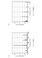
- FIG. 1 shows an example of the thermoelectromotive force measured between the tool and workpiece during turning using a CNC lathe.
- the spindle speed was 500 rpm, and it can be seen that the thermoelectromotive force increases around 0 seconds, causing the cutting point temperature to rise.
- the thermoelectromotive force between the tool and workpiece was obtained by providing an electrical contact at the rear end of the spindle driven by the built-in motor, and therefore the electrical signal (voltage signal) contains a large amount of electromagnetic noise caused by the motor drive.
- Figure 2 shows the results of a frequency analysis of the measured electrical signal.
- the 75 Hz noise component is large in the low frequency region
- the noise components of integer multiples of 5 kHz are large in the high frequency region.
- the spindle rotation frequency is 500/60 ⁇ 8.33 Hz
- 75 Hz is an integer multiple (9 times) of that, so the 75 Hz noise component is thought to be electromagnetic noise caused by magnetic field changes resulting from motor drive.
- the integer multiple component of 5 kHz is thought to be electromagnetic noise caused by the switching frequency being 5 kHz.
- This disclosure has been made in light of these circumstances, and its purpose is to provide technology that prevents electromagnetic noise caused by the spindle motor from being mixed into the electrical signal being measured.
- a processing device includes a spindle to which a tool or a workpiece is attached, a spindle control unit that drives a spindle motor to control the rotation of the spindle, a motion control unit that moves the tool relative to the workpiece, and a measurement unit that measures an electrical signal in an electrical circuit that includes a contact structure that contacts the spindle.
- the measurement unit measures the electrical signal in the electrical circuit when the spindle control unit stops driving the spindle motor.
- Another aspect of the electrical signal measurement method of the present disclosure includes a spindle rotation step of driving a spindle motor to rotate a spindle to which a tool or a workpiece is attached, and a measurement step of stopping the driving of the spindle motor and measuring an electrical signal in an electrical circuit including a contact structure that contacts the spindle.
- FIG. 1 is a diagram showing an example of thermoelectromotive force measured between a tool and a workpiece.
- FIG. 13 is a diagram showing the results of frequency analysis of a measured electrical signal.
- 1 is a diagram showing a schematic configuration of a processing device according to a first embodiment;
- FIG. 2 illustrates an example of a measured electrical signal.
- FIG. 2 is a diagram showing a schematic diagram of a state in which a cutting edge of a tool comes into contact with a workpiece;
- FIG. 13 is a diagram showing the duty ratio calculated for each contact section.
- FIG. 13 is a diagram illustrating an example of a regression curve.
- FIG. 11 is a diagram illustrating a duty ratio calculated from a relational expression.
- FIG. 13 is a diagram showing an example of an electrical signal measured during inertial rotation of a main shaft.
- FIG. 13 is a diagram showing the duty ratio calculated for each contact section.
- FIG. 13 is a diagram showing an example of an electrical signal measured during inertial rotation of a main shaft.
- FIG. 13 is a diagram showing an example of a pulse-shaped electrical signal that is actually measured.
- FIG. 13 is a diagram for explaining a method for calculating a voltage integral value.
- FIG. 13 is a diagram showing the relationship between the area of each voltage pulse and the number of rotations of the spindle.
- FIG. 13 is a diagram showing a schematic configuration of a processing device according to a second embodiment.
- FIG. 1 is a diagram showing the correlation between chip thickness and cutting temperature. 1A shows the change in spindle rotation speed, and FIG. 1B shows the measured thermoelectromotive force between the tool and the workpiece.
- ⁇ Embodiment 1> 3 shows a schematic configuration of the processing device 1a of the embodiment 1.
- the processing device 1a has a function of bringing the cutting tool 20 into contact with the workpiece 30 before the start of full-scale cutting processing, in order to specify the relative positional relationship between the cutting tool 20 and the workpiece 30, and deriving the relative positional relationship.
- the processing device 1a of the first embodiment is a horizontal milling machine or horizontal machining center that rotates the cutting tool 20 attached to the spindle 10 via the holder 32 to cut the blade of the rotating cutting tool 20 into the workpiece 30.
- the spindle 10, the holder 32, the cutting tool 20, the workpiece 30, and the workpiece fixing part 23 are conductors, and the blade of the cutting tool 20 cuts the workpiece 30 at the cutting point 50.
- cutting tools 20 made of conductive tool materials such as cemented carbide, high-speed tool steel, PCD, CBN, etc.
- These tools are often coated, and most coating films are conductive.
- the cutting tool 20 is preferably a conductive diamond (e.g., boron-doped diamond) tool, and may be any of a single crystal diamond tool, a diamond-coated tool, and a polycrystalline diamond tool.
- a conductive diamond e.g., boron-doped diamond
- the processing device 1a is provided with feed mechanisms 24 and 25 on the bed 2 for moving the cutting tool 20 relative to the workpiece 30.
- the workpiece 30 is fixed to the workpiece fixing portion 23, which is supported movably by the feed mechanism 24.
- the spindle housing 12 is supported movably by the feed mechanism 25.
- the feed mechanism 24 moves the workpiece fixing portion 23 in the X-axis direction (front-back direction)
- the feed mechanism 25 moves the spindle housing 12 in the Y-axis direction (up-down direction) and Z-axis direction (left-right direction), so that the feed mechanisms 24 and 25 move the cutting tool 20 relative to the workpiece 30.
- the left-right direction means the axial direction of the spindle 10
- the up-down direction means the vertical direction
- the front-back direction means the direction perpendicular to the axial direction and vertical direction of the spindle 10.
- the feed mechanisms 24 and 25 may be configured to include a motor and a ball screw for each axis.
- the spindle 10 is rotatably supported by the spindle housing 12; specifically, metallic bearings 13a and 13b fixed to the spindle housing 12 rotatably support the spindle 10.
- the rotation mechanism 11 includes a mechanism for rotating the spindle 10, and has a spindle motor and a transmission structure for transmitting the rotational power of the spindle motor to the spindle 10.
- the transmission structure may include a V-belt or gears for transmitting the rotational power of the spindle motor to the spindle 10.
- the rotation mechanism 11 may have a built-in motor built into the spindle 10 and transmit the rotational power directly to the spindle 10.
- the machining device 1a includes a voltage application unit 46 that applies a predetermined voltage between the cutting tool 20 and the workpiece 30.
- the monitoring unit 40 monitors whether or not there is contact between the cutting tool 20 and the workpiece 30.
- the monitoring unit 40 includes a contact structure 41 that is electrically connected to the rear end of the rotating spindle 10, a conductor 42 that is electrically connected to the contact structure 41, a conductor 43 that is electrically connected to the workpiece 30, an electrical resistance 47 provided between the conductors 42 and 43, an electrical resistance 44 provided between the conductors 42 and 43, and a measuring unit 45 that measures the voltage applied to the electrical resistance 44.
- the conductor 42, the contact structure 41, the spindle 10, the holder 32, the cutting tool 20, the workpiece 30, the workpiece fixing unit 23, the conductor 43, the electrical resistance 44, and the electrical resistance 47 form an electrical circuit.
- the measurement unit 45 measures the electrical signal in the electrical circuit, specifically, the voltage signal applied to the electrical resistance 44.
- the monitoring unit 40 monitors the voltage change in the electrical resistance 44 caused by contact between the cutting tool 20 and the workpiece 30, and detects whether or not the cutting tool 20 and the workpiece 30 are in contact.
- the measuring unit 45 may also have a function of measuring the current flowing through the electrical resistance 44.
- the conductor 43 is connected to the workpiece fixing part 23 that fixes the workpiece 30, and the contact structure 41 contacts the center of rotation of the spindle 10. Since the peripheral speed of the center of rotation is theoretically zero, the contact structure 41 contacting the center of rotation of the spindle 10 can suppress wear at the contact point.
- the electrical resistor 47 is provided for the purpose of preventing electrical noise from occurring when the cutting tool 20 and the workpiece 30 are not in contact. If the noise-suppressing electrical resistor 47 is not provided, the electrical circuit is open when the cutting tool 20 and the workpiece 30 are not in contact, and the monitoring unit 40 detects the contact between the cutting tool 20 and the workpiece 30 by detecting the continuity of the electrical circuit when the cutting tool 20 and the workpiece 30 come into contact.
- the monitoring unit 40 employs an electrical circuit that does not have the noise-suppressing electrical resistor 47. Therefore, the monitoring unit 40 monitors the presence or absence of contact between the cutting tool 20 and the workpiece 30 based on the presence or absence of continuity of the electrical circuit.
- the control unit 100 of the first embodiment executes a contact detection process to detect contact between the cutting tool 20 and the workpiece 30.
- the control unit 100 includes a motion control unit 101 that controls the motion of the cutting tool 20 and/or the workpiece 30, an acquisition unit 104 that acquires the electrical signals measured by the measurement unit 45, and a processing unit 105 that processes the electrical signals acquired by the acquisition unit 104.
- the processing unit 105 identifies the relative positional relationship between the cutting tool 20 and the workpiece 30 from the electrical signals acquired by the acquisition unit 104.
- the motion control unit 101 has a spindle control unit 102 that drives the spindle motor of the rotation mechanism 11 to control the rotation of the spindle 10, and a movement control unit 103 that controls the relative movement (feed movement) between the cutting tool 20 and the workpiece 30 by the feed mechanisms 24, 25.
- the cutting tool 20 is attached to the spindle 10
- the workpiece 30 may be attached to the spindle 10
- the processing device 1a may be configured as a turning device.
- Each element described as a functional block of the control unit 100 can be configured in hardware as a circuit block, memory, other LSIs, a CPU, etc., and in software as a system software or an application program loaded into memory. Therefore, those skilled in the art will understand that these functional blocks can be realized in various forms by hardware alone, software alone, or a combination of both, and are not limited to any one of them.
- the electrical signal from the cutting tool 20 is taken from a contact structure 41 that contacts the rear end of the spindle 10.
- the spindle 10 and the spindle housing 12 are electrically insulated, but here the bearings 13a and 13b are made of metal, and the spindle 10 in a stopped state (non-rotating state) is short-circuited with the spindle housing 12.
- the present inventor has found that when the spindle 10 rotates at a rotational speed equal to or higher than a predetermined rotational speed RS, a fluid lubrication state is created in the bearings 13a, 13b, and the lubricating oil causes the spindle 10 and the spindle housing 12 to lose electrical continuity.
- the movement control unit 103 controls the feed mechanisms 24, 25 to cut the cutting tool 20 into the workpiece 30, and the acquisition unit 104 acquires the voltage signal measured by the measurement unit 45 together with time information (time stamp) and records it in a memory (not shown).
- the rotational speed RS depends on the bearing, but may be about several hundred revolutions per minute. Therefore, in the machining device 1a, the measurement unit 45 can measure the voltage at the electrical resistance 44 without adding an insulating component between the spindle 10 and the spindle housing 12.
- the main shaft 10 and the rotating mechanism 11 also need to be electrically insulated.
- the V-belt may be made of an insulating material such as rubber to electrically insulate the main shaft 10 and the rotating mechanism 11.
- the rotating mechanism 11 uses gears as the power transmission structure, a fluid lubrication state is created between the rotating gears as described above, and lubricating oil is interposed between the meshing teeth, electrically insulating the main shaft 10 and the rotating mechanism 11. Therefore, in the processing device 1a, the measuring unit 45 can measure the voltage at the electrical resistance 44 without adding an insulating part between the main shaft 10 and the rotating mechanism 11.
- the movement control unit 103 moves the cutting tool 20 relative to the workpiece 30 from a position where the cutting tool 20 and the workpiece 30 are separated, in the direction in which they come into contact (Y-axis direction (up and down)).
- the processing unit 105 analyzes the electrical signal measured by the measuring unit 45 after the tool cutting edge begins to cut (or contact) the workpiece 30, and derives the relative positional relationship.
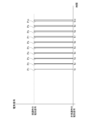
- FIG. 4 shows an example of an electrical signal measured by the measuring unit 45.
- the measuring unit 45 measures an electrical signal that indicates the presence or absence of contact between the cutting tool 20 and the workpiece 30.
- the vertical axis represents the electrical signal (here, a voltage signal) measured by the measuring unit 45
- the horizontal axis represents the time when the cutting tool 20 and the workpiece 30 are moved relatively (approaching each other) at a constant feed speed. Note that if the feed speed changes, the horizontal axis may represent the coordinate value of the feed mechanism 24.
- the cutting tool 20 used is a single-edged (single-blade) milling tool.
- the monitoring unit 40 detects continuity only during the period when the tool cutting edge is in contact with the workpiece 30, and specifically, the measuring unit 45 measures pulse-like voltages P1 to P10 .
- the conduction period corresponds to the angle at which the tool cutting edge contacts the workpiece 30, and the conduction period increases as the contact angle as viewed from the center of rotation increases. If an electrical resistor 47 for noise reduction is provided in the electrical circuit, the measuring unit 45 measures a voltage different from that during the period when the tool cutting edge is in contact with the workpiece 30 compared to the period when it is not in contact.
- FIG. 5 shows a schematic diagram of the state in which the cutting edge of the tool contacts the workpiece. If the contact surface of the workpiece 30 that the cutting edge contacts can be regarded as a plane, and the tool feed amount per rotation is small relative to the tool cutting edge radius R, the cycle in which the moment of the midpoint of the conduction period is repeated is approximately equal to the rotation cycle T of the spindle 10.
- the tool cutting edge radius R indicates the radius of the outermost point of the cutting tool 20 (the cutting edge position located at the outermost periphery during rotation), and therefore the rotation locus circle represents the rotation locus of the outermost point of the tool.
- FIG. 4 shows 10 voltage pulses P 1 to P 10 measured in a time series, and as the cutting depth deepens over time, the contact angle section (2 ⁇ ) becomes larger, and the pulse width of the voltage pulse becomes longer over time.
- the measuring unit 45 measures an electrical signal (voltage signal) indicating the presence or absence of contact between the cutting tool 20 and the workpiece 30 and supplies it to the control unit 100, and the acquiring unit 104 acquires the measured electrical signal together with time information and records it in memory. At this time, it is preferable for the acquiring unit 104 to record the electrical signal in memory together with position information of the feed mechanism.
- the electrical signal recorded in the memory may be a digital value obtained by A/D converting the voltage waveform.
- the movement control unit 103 stops the relative movement of the cutting tool 20 and the workpiece 30 in the cutting direction and stops the cutting that was being performed for the process of identifying the relative positional relationship (part of the setup).
- the movement control unit 103 may stop cutting by moving the cutting tool 20 and the workpiece 30 relatively in a direction that separates them. By making the cutting depth at this time less than the actual machining allowance (for example, the cutting depth during finish machining), it is possible to prevent cutting marks from the setup from remaining on the final machined surface.
- the processing unit 105 has a function of identifying the position where the workpiece 30 reaches the rotation locus circle of the outermost periphery of the cutting tool 20 from one or more voltage pulse signals.
- the position where the workpiece 30 reaches the rotation locus circle may be the position of the workpiece 30 relative to the rotation center position when the rotation locus circle comes into contact with the contact surface of the workpiece 30 in FIG. 5.
- the processing unit 105 can specify, from one voltage pulse P1 , the position at which the workpiece 30 reaches the rotation locus circle of the outermost point of the cutting tool 20. With reference to Fig. 5, the processing unit 105 can specify the position at which the workpiece 30 reaches the rotation locus circle of the outermost point of the cutting tool 20 by deriving the depth (maximum depth) d that the cutting edge of the cutting tool 20 cuts into the contact surface of the workpiece 30 when the cutting tool 20 and the workpiece 30 first come into contact with each other.
- the processing unit 105 identifies a time interval (conduction period) during which the cutting tool 20 and the workpiece 30 are in contact with each other from the electric signal acquired by the acquisition unit 104 and recorded in the memory.
- the time interval during which the cutting tool 20 and the workpiece 30 are in contact with each other is a period (contact period) from the start of contact to the end of contact, and the processing unit 105 identifies the pulse width W1 of the voltage pulse P1 as the contact period.
- the processing unit 105 calculates the ratio of the pulse width W1 of the voltage pulse P1 to the rotation period T of the cutting tool 20, that is, the duty ratio ( W1 /T).
- the processing unit 105 may acquire the rotation period T from the rotation synchronization signal, but when a rotation synchronization signal is not obtained, the interval between the moment when the pulse width W1 of the adjacent voltage pulse P1 becomes the midpoint and the moment when the pulse width W2 of the voltage pulse P2 becomes the midpoint may be regarded as the rotation period T.
- the relationship between the cutting depth d and the duty ratio D can be derived as follows.
- the twist angle of the contacting end mill tool is 0 degrees and the contact surface of the workpiece 30 is a plane parallel to the tool rotation axis as shown in Fig. 5
- the angle section (angle range) 2 ⁇ in which the cutting tool 20 contacts the workpiece 30 with respect to the cutting depth d from the surface of the workpiece 30 is derived as follows.
- the duty ratio D ( 2 ⁇ /2 ⁇ ), which is the ratio of the contact angle section 2 ⁇ to one revolution, is It is calculated as follows.
- the processing unit 105 can derive the maximum depth d of the rotation locus circle (see FIG. 5) of the outermost point of the cutting tool 20 penetrating into the contact surface of the workpiece 30 from one voltage pulse P1 . Therefore, the processing unit 105 can specify the relative positional relationship between the cutting tool 20 and the workpiece 30 using the cutting depth d. Specifically, the processing unit 105 specifies that the rotation locus circle of the outermost point of the cutting tool 20 reaches the workpiece 30 at a position where the cutting tool 20 is moved by a distance d in the opposite direction to the tool feed direction. The position where the rotation locus circle of the outermost point of the cutting tool 20 reaches the workpiece 30 corresponds to the cutting start position of the cutting tool 20. Note that when the angle section 2 ⁇ where the cutting tool 20 contacts the workpiece 30 can be measured by an angle measuring unit using an encoder or the like, the maximum depth d may be derived from the measured angle section 2 ⁇ .
- the processing unit 105 can identify the position where the workpiece 30 reaches the rotation locus circle of the outermost peripheral point of the cutting tool 20 from the multiple voltage pulses P 1 to P 10. In the first embodiment, ten voltage pulses are used, but a multiple number of voltage pulses other than ten may be used.
- the processing unit 105 identifies a contact section (conduction period) during which the cutting tool 20 and the workpiece 30 are in contact with each other from the time-series data of the electrical signal acquired by the acquisition unit 104 and recorded in the memory. The processing unit 105 then identifies the moment of the midpoint of the pulse width of each of the voltage pulses P 1 to P 10 to derive times t 1 to t 10. If the feed amount per rotation is minute with respect to the tool cutting edge radius R as described above, the interval between adjacent times t 1 to t 10 can be regarded as substantially the rotation period T.
- the time t n (2 ⁇ n ⁇ 10) may be determined by (time t 1 + rotation period T ⁇ (n-1)).
- the times t 2 to t 10 corresponding to the rotation periods included in the time intervals of the voltage pulses P 2 to P 10 may be determined starting from the time t 1 .
- the processing unit 105 calculates the ratio of the contact section to the rotation period T for each time section (contact section), i.e., the duty ratio.
- the maximum duty ratio is 50%, but if the feed amount cannot be considered small, the maximum duty ratio may slightly exceed 50%.
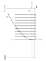
- the processing unit 105 statistically processes the duty ratios of the multiple contact sections, performs curve approximation of the change in the duty ratio, and determines the time at which the approximated regression curve (regression equation) crosses zero (the time at which the duty ratio becomes 0).
- FIG. 7 shows an example of a regression curve 60 calculated by the processing unit 105.
- the processing unit 105 performs regression analysis of the duty ratios of multiple contact sections to obtain a regression curve (regression equation) 60, and uses the obtained regression curve 60 to derive the position at which the contacted surface of the workpiece 30 reaches the rotation locus circle of the outermost point of the cutting tool 20.
- the processing unit 105 obtains the time t0 at which the duty ratio of the calculated regression curve 60 becomes 0.
- the position at which the rotation locus circle of the outermost point of the cutting tool 20 reaches the workpiece 30 corresponds to the cutting start position of the cutting tool 20.
- the processing unit 105 identifies the time interval during which the cutting tool 20 and the workpiece 30 are in contact from the time series data of the electrical signal acquired by the acquisition unit 104, and identifies the time t 0 at which the workpiece 30 reaches the rotation locus circle of the outermost peripheral point of the cutting tool 20 from the identified multiple time intervals, and identifies the positions of the cutting tool 20 and the workpiece 30 at that time t 0.
- the processing unit 105 can derive an accurate cutting start position of the cutting tool 20.
- the rotational speed of the spindle 10 is constant, and the feed speed of the workpiece 30 relative to the cutting tool 20 is constant.
- the contact angle section 2 ⁇ can be measured by an angle measurement unit using an encoder or the like, the rotational speed of the spindle 10 does not necessarily have to be constant, and if the position information of the feed mechanism of the workpiece 30 relative to the cutting tool 20 can be measured, the feed speed does not necessarily have to be constant.
- the processing unit 105 may identify the angle section 2 ⁇ in which the cutting tool 20 and the workpiece 30 are in contact, and identify the feed position at which the workpiece 30 reaches the rotation locus circle of the outermost point of the cutting tool 20 from the identified multiple angle sections.
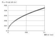
- Figure 8 shows the duty ratio calculated from relational expression (1).
- the vertical axis represents the duty ratio (2 ⁇ /2 ⁇ ), and the horizontal axis represents the cutting depth d.
- R 10 mm.
- the processing unit 105 may derive the regression curve 60 (see FIG. 7 ) based on the relational expression (1). For example, the processing unit 105 specifies the origin of the horizontal axis (a point on the zero line 62 (time t 0 )) so that the error evaluation value (for example, the sum of squares of deviations) from the relational expression (1) is the smallest for the multiple x marks shown in FIG. 7 .
- the error evaluation value for example, the sum of squares of deviations
- the processing unit 105 obtains the relationship between the duty ratio and the cutting depth, and specifies the origin of the horizontal axis of the relational expression (1) so as to fit the multiple duty ratios measured for each rotation period T, thereby specifying the time t 0 at the moment when the workpiece 30 reaches the virtual rotation locus circle of the outermost periphery of the tool, and can accurately specify the positions of the cutting tool 20 and the workpiece 30 at this time t 0 .
- the processing unit 105 may also identify the origin of the horizontal axis so that another error evaluation value, for example the sum of the absolute values of the errors, is minimized.
- the tool cutting edge radius R is assumed to be known, but it may be unknown.
- the processing unit 105 adjusts the value of the tool cutting edge radius R so that the error evaluation value (for example, the sum of squares of deviations) from the relational expression (1) is minimized for the multiple x marks shown in Fig. 7, and then identifies the origin of the horizontal axis (a point on the zero line 62 (time t0 )). In this case, the processing unit 105 can not only identify the origin of the horizontal axis of the relational expression (1), but also identify the tool cutting edge radius R at the same time.
- the relationship between the time on the horizontal axis and the relative position of the tool cutting edge and the surface of the workpiece can be found using information in the control device of the machine tool.
- the acquisition unit 104 records in memory an electrical signal indicating the presence or absence of contact at the same time as the position information (measured value or command value) of the feed mechanism moving for the contact operation, so that the processing unit 105 can identify the position at each time. If this simultaneous recording is difficult, the acquisition unit 104 may record in memory in a chronological order the signal indicating the presence or absence of contact when approaching at a constant speed, while recording in memory the position information at the moment when the approach operation is commanded to stop.
- the processing unit 105 can calculate the position of the section where the tool cutting edge is in contact with the surface of the workpiece using the electrical signals recorded in chronological order, the position information when the last electrical signal was acquired, and the constant approach speed. If time information is recorded in the memory, the processing unit 105 can calculate the position of the section where the tool cutting edge is in contact with the surface of the workpiece using the electrical signals recorded in chronological order and the position information when the last electrical signal was acquired.
- the machining device 1a stops driving the spindle motor and rotates the spindle 10 by inertia while measuring the electrical signal.
- stopping the driving of the spindle motor may mean stopping the supply of power to the spindle motor. Since the spindle 10 has inertia, when the driving of the spindle motor is stopped while the spindle 10 is rotating, the rotation speed of the spindle 10 gradually decreases, but the rotation of the spindle 10 does not stop immediately. In this way, the measuring unit 45 can theoretically solve the problem of electromagnetic noise being mixed into the electrical signal by measuring the electrical signal in the electrical circuit when the spindle control unit 102 stops driving the spindle motor.
- an allowable limit rotational speed (e.g., rotational speed RS) may be set in advance, and when the rotational speed falls below the limit rotational speed or approaches the limit rotational speed, the movement control unit 103 may move the cutting tool 20 in a direction away from the workpiece 30.
- the rotational speed changes (decreases) during the contact detection process, but by acquiring the electrical signal of the contact detection process while measuring the rotational position and/or rotational speed during the inertial rotation of the spindle 10, the contact position can be identified without being affected by electromagnetic noise caused by the drive of the spindle motor.
- FIG. 9 shows an example of an electrical signal measured by the measuring unit 45 during inertial rotation of the spindle.
- the vertical axis represents the electrical signal (here, a voltage signal) measured by the measuring unit 45
- the horizontal axis represents the time when the cutting tool 20 and the workpiece 30 are moved relatively (approaching each other) at a constant feed rate.
- the cutting tool 20 used is a single-edged (one-blade) milling tool.
- the spindle control unit 102 drives the spindle motor in the rotating mechanism 11 to rotate the spindle 10 at a predetermined rotation speed, and then stops the power supply to the spindle motor to stop the drive of the spindle motor. Therefore, the spindle 10 loses rotational power and starts to rotate by inertia.
- the movement control unit 103 brings the cutting tool 20 close to the workpiece 30 at a constant feed rate, and the measurement unit 45 measures the electric signal in the electric circuit.
- the monitoring unit 40 detects the conduction only during the period when the tool cutting edge is in contact with the workpiece 30, and specifically, the measurement unit 45 measures the pulse-like voltages P' 1 to P' 10. Since the drive of the spindle motor is stopped, the measurement unit 45 can measure the electric signal that does not include electromagnetic noise caused by the drive of the spindle motor.
- the processing unit 105 identifies the contact section where the cutting tool 20 and the workpiece 30 are in contact from the electric signal measured by the measuring unit 45, and identifies the relative positional relationship between the cutting tool 20 and the workpiece 30 from the identified contact section. In the first embodiment, the processing unit 105 identifies the position where the workpiece 30 reaches the rotation locus circle of the outermost periphery of the cutting tool 20 from the multiple voltage pulses P' 1 to P' 10. The processing unit 105 identifies the contact section where the cutting tool 20 and the workpiece 30 are in contact from the time series data of the electric signal acquired by the acquiring unit 104 and recorded in the memory.
- the contact section is the section from the start of contact to the end of contact, and is equal to the pulse width.
- the processing unit 105 identifies the moment of the midpoint of the pulse widths W' 1 to W' 10 of each voltage pulse P' 1 to P' 10 , and derives the times t' 1 to t' 10 .
- the interval T n between adjacent voltage pulses can be expressed as (t' n+1 -t' n ).
- the processing unit 105 calculates the ratio of the contact section to the pulse interval Tn , i.e., the duty ratio ( W'n / Tn ), for each contact section.
- the processing unit 105 statistically processes the duty ratios of a plurality of contact sections, performs curve approximation of the change in the duty ratio, and determines the time at which the approximated regression curve (regression equation) crosses zero (the time at which the duty ratio becomes 0). In this example, the processing unit 105 performs regression analysis of the duty ratios of a plurality of contact sections to determine a regression curve (regression equation) 60, and derives the position at which the contacted surface of the workpiece 30 reaches the rotation locus circle of the outermost periphery point of the cutting tool 20 using the determined regression curve 60.
- the processing unit 105 determines the time t'0 at which the duty ratio of the calculated regression curve 60 becomes 0.
- the position at which the rotation locus circle of the outermost point of the cutting tool 20 reaches the workpiece 30 corresponds to the cutting start position of the cutting tool 20.
- the processing unit 105 identifies a contact section where the cutting tool 20 and the workpiece 30 are in contact from the time-series data of the electrical signal acquired by the acquisition unit 104, and identifies the time t'0 at which the workpiece 30 reaches the rotation locus circle of the outermost peripheral point of the cutting tool 20 from the identified multiple contact sections.
- the processing unit 105 identifies the relative positional relationship between the cutting tool 20 and the workpiece 30 by identifying the feed amount of the feed mechanisms 24, 25 at the time t'0 .
- the processing unit 105 can identify the time t'0 with high accuracy by stopping the drive of the spindle motor to suppress electromagnetic noise caused by the drive of the spindle motor from being mixed into the electrical signal.
- FIG. 11 shows another example of an electrical signal measured by the measuring unit 45 during inertial rotation of the spindle.
- the vertical axis represents the electrical signal (here, a voltage signal) measured by the measuring unit 45
- the horizontal axis represents the rotational position of the spindle 10.
- the cutting tool 20 used is a single-edged (single-blade) milling tool.
- the processing unit 105 may derive the relationship between the rotational position and the electrical signal by measuring the rotational position of the spindle 10 during continuity detection.
- the processing unit 105 can also derive the relationship between the feed position and the electrical signal by measuring the feed amount of the feed mechanisms 25, 26 during continuity detection.
- the processing unit 105 identifies a contact section where the cutting tool 20 and the workpiece 30 are in contact with each other from the time series data of the electric signal acquired by the acquisition unit 104 and recorded in the memory.
- the contact section is a section from the start of contact to the end of contact, and is equal to the pulse width.
- the processing unit 105 identifies the moment of the midpoint of the pulse widths W'' 1 to W'' 10 of each voltage pulse P'' 1 to P'' 10 , and derives the rotation positions l 1 to l 10.
- the interval (l n+1 -l n ) between adjacent voltage pulses is a constant value L, which corresponds to the rotation angle of one revolution (360 degrees).
- the processing unit 105 calculates a value (W'' n /L) obtained by dividing the contact section by the pulse interval L.
- the processing unit 105 statistically processes a plurality of (contact sections/pulse intervals), performs curve approximation of changes in the (contact section/pulse interval), and determines the position where the approximated regression curve (regression equation) crosses zero.
- the processing unit 105 performs regression analysis of a plurality of (contact sections/pulse intervals) to determine a regression curve (regression equation) 70, and derives the rotation position at which the contacted surface of the workpiece 30 reaches the rotation locus circle of the outermost peripheral point of the cutting tool 20 using the determined regression curve 70.
- the processing unit 105 determines a rotational position l0 at which the calculated regression curve 70 becomes 0.
- the rotational position l0 specified by the intersection of the regression curve 70 and the zero line 72 is a position where the contacted surface of the workpiece 30 reaches the rotation locus circle (see FIG. 5 ) of the outermost point of the cutting tool 20, that is, a position where the contacted surface of the workpiece 30 touches the rotation locus circle.
- the rotational position l0 at which the rotation locus circle of the outermost point of the cutting tool 20 reaches the workpiece 30 corresponds to the moment when the cutting tool 20 starts cutting.
- the processing unit 105 identifies a contact section where the cutting tool 20 and the workpiece 30 are in contact from the time series data of the electrical signal acquired by the acquisition unit 104, and identifies a rotational position l0 at which the workpiece 30 reaches the rotation locus circle of the outermost periphery of the cutting tool 20 from the identified multiple contact sections.
- the processing unit 105 can identify the relative positional relationship between the cutting tool 20 and the workpiece 30 by identifying the feed amount of the feed mechanisms 24, 25 at the rotational position l0 .
- the processing unit 105 can identify the rotational position l0 with high accuracy by stopping the drive of the spindle motor to suppress electromagnetic noise caused by the drive of the spindle motor from being mixed into the electrical signal.
- FIG. 12(a) shows an example of multiple pulsed electric signals actually measured in the contact detection process
- FIG. 12(b) shows an example of an enlarged shape of one pulsed electric signal.
- the cutting tool 20 is coated with a coating with high contact resistance (e.g., a ceramic thin film coating)
- the measured voltage pulse may be significantly deformed from a square wave and the pulse width may not be clear. If the pulse width is unclear, it becomes difficult for the processing unit 105 to accurately identify the contact section, that is, the section from the start to the end of contact. Therefore, the processing unit 105 may identify the contact position using the area of the voltage pulse (voltage integral value) instead of the pulse width.
- FIG. 12(b) is a diagram for explaining the area of the voltage pulse (voltage integral value).
- the processing unit 105 calculates the voltage integral value in the section (integration period) from when the voltage signal exceeds the reference value to when it returns to the reference value from the time series data of the electrical signal acquired by the acquisition unit 104.
- the processing unit 105 calculates the voltage integral value by integrating (voltage signal - voltage during non-contact) during the integration period (specifically, accumulating and multiplying by the time interval).
- the reference value can be set as a value obtained by adding a value exceeding the amount of fluctuation (e.g., three times the standard deviation, twice the difference between the maximum value and the minimum value, etc.) to the average value of the voltage during non-contact during the period when there is no reliable contact (e.g., the period before the start of the feed motion for contact).
- the voltage during non-contact and the reference value are approximate values, so the processing unit 105 may calculate the voltage integral value by integrating (voltage signal - reference value) during the integration period.
- FIG. 13 is a diagram for explaining a method for calculating the voltage integral value more accurately.
- the processing unit 105 determines the moment that is the midpoint of each interval from when the voltage signal exceeds the reference value until it returns to the reference value (called the "contact midpoint").
- the processing unit 105 may then determine the moment that is the midpoint of adjacent contact midpoints, and calculate the voltage integral value using the integration period between the two midpoints.
- the start point of the first integration period may be the moment that is one integration period, or one rotation period, back in time from the first contact midpoint.
- the processing unit 105 calculates a voltage integral value for each measured voltage pulse (pulse-like electrical signal) and identifies the relative positional relationship between the cutting tool 20 and the workpiece 30 from the calculated multiple voltage integral values.
- the spindle control unit 102 continues the feed motion from when the cutting tool 20 and the workpiece 30 come into contact with each other until the fifth rotation of the spindle 10, and then stops the feed motion thereafter. Therefore, after the fifth rotation, the cutting tool 20 does not cut the workpiece 30.
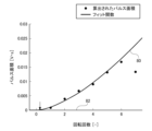
- FIG. 14 shows the relationship between the area of each voltage pulse and the number of rotations of the spindle 10.
- contact occurs at the first rotation and the feed motion continues until the fifth rotation, so the processing unit 105 identifies the contact position using the pulse area (voltage integral value) from the first rotation to the fifth rotation.
- the processing unit 105 curve fits the five pulse area points from the first rotation to the fifth rotation to generate a regression curve 80 and finds the intersection with the zero line 82.
- the point indicated by the arrow corresponds to the position where the workpiece 30 reaches the rotation trajectory circle of the outermost point of the cutting tool 20.
- the machining device 1a may determine the relative positional relationship between the cutting tool 20 and the workpiece 30 using the area of the voltage pulse (voltage integral value) rather than the pulse width, especially when the measured voltage pulse is significantly deformed from a square wave.
- ⁇ Embodiment 2> 15 shows a schematic configuration of a processing device 1b of embodiment 2.
- components denoted by the same reference numerals as those in the processing device 1a of embodiment 1 have the same or similar structure and function as those in the processing device 1a.
- the monitoring unit 40 monitors the thermoelectromotive force generated between the cutting tool 20 and the workpiece 30 during cutting.
- the monitoring unit 40 includes a contact structure 41 electrically connected to the rotating spindle 10, a conductor 42 electrically connected to the contact structure 41, a conductor 43 electrically connected to the workpiece 30, an electrical resistance 44 provided between the conductors 42 and 43, and a measuring unit 45 that measures the thermoelectromotive force (voltage) between the contact structure 41 and the cutting point 50.
- the conductor 42, the contact structure 41, the spindle 10, the holder 32, the cutting tool 20, the workpiece 30, the workpiece fixing portion 23, the conductor 43, and the electrical resistance 44 constitute an electrical circuit.
- the measuring unit 45 measures an electrical signal in the electrical circuit, specifically, a voltage signal applied to the electrical resistance 44.
- the control unit 100 of the second embodiment performs machining process monitoring using the thermoelectromotive force between the tool and the workpiece.
- the control unit 100 includes a motion control unit 101 that controls the motion of the cutting tool 20 and/or the workpiece 30, an acquisition unit 104 that acquires the electrical signal measured by the measurement unit 45, and a processing unit 105 that processes the electrical signal acquired by the acquisition unit 104.
- the processing unit 105 determines the state of the machining process based on the voltage value of the electrical signal acquired by the acquisition unit 104.
- the motion control unit 101 has a spindle control unit 102 that drives the spindle motor of the rotation mechanism 11 to control the rotation of the spindle 10, and a movement control unit 103 that controls the relative movement (feed movement) between the cutting tool 20 and the workpiece 30 by the feed mechanisms 24, 25.
- the cutting tool 20 is attached to the spindle 10
- the workpiece 30 may be attached to the spindle 10
- the processing device 1b may be configured as a turning device.
- the processing unit 105 has a function of calculating the cutting temperature from the voltage measured by the measuring unit 45 by using a temperature conversion curve or a temperature conversion table for converting the thermoelectromotive force into the cutting temperature (the temperature of the cutting point 50). When there is no information for converting the thermoelectromotive force into the cutting temperature, the processing unit 105 may calculate the relative increase or decrease in temperature without calculating the temperature value.
- Each element described as a functional block of the control unit 100 can be configured in hardware as a circuit block, memory, other LSIs, a CPU, etc., and in software as a system software or an application program loaded into memory. Therefore, those skilled in the art will understand that these functional blocks can be realized in various forms by hardware alone, software alone, or a combination of both, and are not limited to any one of them.
- the processing unit 105 may obtain the cutting temperature from the voltage measured by the measuring unit 45 during cutting and determine the state of the machining process. For example, if the cutting temperature falls outside a predetermined range or the fluctuation of the cutting temperature exceeds a predetermined value, the processing unit 105 may determine that there is some abnormality in the machining process including the shape of the workpiece, the fixation of the workpiece, and the state of the tool.
- the processing unit 105 of embodiment 2 may determine whether the machining process is normal or abnormal by determining the cutting temperature from the voltage measured by the measurement unit 45 and monitoring the state of the machining process with reference to the correlation shown in FIG. 16. Note that if there is a curve or table showing the correlation between the cutting thickness and the thermoelectromotive force, or if the value or range of the thermoelectromotive force corresponding to a normal machining process is empirically known, the processing unit 105 may determine the state of the machining process from the voltage measured by the measurement unit 45 without determining the cutting temperature.
- FIG. 1 shows a thermoelectromotive force (voltage signal) mixed with electromagnetic noise caused by motor drive.
- the machining device 1b stops driving the spindle motor and rotates the spindle 10 by inertia while measuring the electrical signal. Since the spindle 10 has inertia, when the spindle motor is stopped while the spindle 10 is rotating, the rotation speed of the spindle 10 gradually decreases, but the spindle 10 does not stop rotating immediately. In this way, the measurement unit 45 can theoretically solve the problem of electromagnetic noise being mixed into the electrical signal by measuring the electrical signal in the electrical circuit when the spindle control unit 102 stops driving the spindle motor. Note that the measurement of the rotation state by the encoder or the like may continue while the spindle motor is stopped. For example, the spindle control unit 102 may resume driving the spindle motor when the rotation speed falls below or approaches a preset allowable limit rotation speed (for example, rotation speed RS).
- a preset allowable limit rotation speed for example, rotation speed RS
- the rotation speed changes (decreases) while the thermoelectromotive force is being measured, but by acquiring an electrical signal for monitoring the machining process while measuring the rotation position and/or rotation speed during the inertial rotation of the spindle 10, it is possible to monitor the state of the machining process at a specified rotation speed without being affected by electromagnetic noise caused by the drive of the spindle motor.
- the spindle control unit 102 increases the rotational speed of the spindle 10 to a speed slightly higher than the target rotational speed, then stops the spindle motor, and the measurement unit 45 measures the thermoelectromotive force at the moment when the rotational speed gradually decreases to the target rotational speed.
- the measurement unit 45 measures the thermoelectromotive force while the spindle 10 is rotating by inertia, allowing the processing unit 105 to perform accurate process monitoring.
- Fig. 17(a) shows the change in the rotation speed of the spindle 10
- Fig. 17(b) shows the measured thermoelectromotive force between the tool and the workpiece.
- the spindle control unit 102 drives the spindle motor so that the rotation speed of the spindle 10 becomes Rt .
- the spindle control unit 102 increases the rotation speed of the spindle 10 above Rt , and at time ts , stops driving the spindle motor.
- the spindle 10 rotates by inertia from time ts to time te , and at time te , the drive of the spindle motor is resumed to return the rotation speed of the spindle 10 to Rt .
- the processing unit 105 measures the cutting point temperature using the electrical signal acquired during the period from time t s to time te .
- the processing unit 105 may measure the cutting point temperature using the electrical signal acquired at time t t when the rotation speed becomes R t .
- the processing unit 105 can determine the state of the machining process under the target cutting conditions.
- a machining apparatus includes a spindle to which a tool or a workpiece is attached, a spindle control unit that drives a spindle motor to control rotation of the spindle, a movement control unit that moves the tool relative to the workpiece, and a measurement unit that measures an electrical signal in an electrical circuit including a contact structure in contact with the spindle, and the measurement unit measures the electrical signal in the electrical circuit when the spindle control unit stops driving the spindle motor.
- This type of machining device can prevent electromagnetic noise caused by the drive of the spindle motor from being mixed into the electrical signal being measured.
- the measuring unit may measure the electrical signal in the electrical circuit when the spindle is rotating by inertia. This makes it possible to measure an electrical signal that is not contaminated by electromagnetic noise caused by the drive of the spindle motor.
- the machining device may include an acquisition unit that acquires the electrical signal measured by the measurement unit, and a processing unit that processes the electrical signal acquired by the acquisition unit.
- the processing unit may identify a section where the tool and the workpiece are in contact from the electrical signal, and identify the relative positional relationship between the tool and the workpiece from the identified section.
- the processing unit may determine the state of the machining process based on the voltage value of the electrical signal.
- Another aspect of the electrical signal measurement method of the present disclosure is a method for measuring an electrical signal, which includes a spindle rotation step of driving a spindle motor to rotate a spindle to which a tool or a workpiece is attached, and a measurement step of stopping the drive of the spindle motor to measure an electrical signal in an electrical circuit including a contact structure that contacts the spindle.
- This electrical signal measurement method can prevent electromagnetic noise caused by the drive of the spindle motor from being mixed into the electrical signal being measured.
- the measuring step may include measuring an electrical signal in an electrical circuit while the spindle is coasting.
- a processing device includes a spindle to which a tool or a workpiece is attached, a spindle control unit that drives a spindle motor to control the rotation of the spindle, a movement control unit that moves the tool relative to the workpiece in a direction in which the tool and the workpiece come into contact, an acquisition unit that acquires a voltage signal that indicates whether or not the tool and the workpiece are in contact, and a processing unit that calculates a voltage integral value by integrating the voltage signal acquired by the acquisition unit over an integration period and determines the relative positional relationship between the tool and the workpiece from the calculated voltage integral value.
- the processing unit may calculate a plurality of voltage integral values from the time series data of the voltage signal acquired by the acquisition unit, and identify the relative positional relationship between the tool and the workpiece from the calculated plurality of voltage integral values.
- the method disclosed herein can be used in processing equipment that cuts workpieces.
Landscapes
- Engineering & Computer Science (AREA)
- Mechanical Engineering (AREA)
- Machine Tool Sensing Apparatuses (AREA)
Priority Applications (2)
| Application Number | Priority Date | Filing Date | Title |
|---|---|---|---|
| PCT/JP2023/002892 WO2024161466A1 (ja) | 2023-01-30 | 2023-01-30 | 加工装置および電気信号測定方法 |
| JP2024574078A JPWO2024161466A1 (https=) | 2023-01-30 | 2023-01-30 |
Applications Claiming Priority (1)
| Application Number | Priority Date | Filing Date | Title |
|---|---|---|---|
| PCT/JP2023/002892 WO2024161466A1 (ja) | 2023-01-30 | 2023-01-30 | 加工装置および電気信号測定方法 |
Publications (1)
| Publication Number | Publication Date |
|---|---|
| WO2024161466A1 true WO2024161466A1 (ja) | 2024-08-08 |
Family
ID=92146174
Family Applications (1)
| Application Number | Title | Priority Date | Filing Date |
|---|---|---|---|
| PCT/JP2023/002892 Ceased WO2024161466A1 (ja) | 2023-01-30 | 2023-01-30 | 加工装置および電気信号測定方法 |
Country Status (2)
| Country | Link |
|---|---|
| JP (1) | JPWO2024161466A1 (https=) |
| WO (1) | WO2024161466A1 (https=) |
Citations (9)
| Publication number | Priority date | Publication date | Assignee | Title |
|---|---|---|---|---|
| JPS5511706A (en) * | 1978-06-29 | 1980-01-26 | Toyoda Mach Works Ltd | Contact detector |
| JPS5560550U (https=) * | 1978-10-20 | 1980-04-24 | ||
| JPS5639852A (en) * | 1979-09-03 | 1981-04-15 | Hitachi Ltd | Abnormality detector for cutting tool of machine tool |
| JPS63174873A (ja) * | 1987-01-09 | 1988-07-19 | Disco Abrasive Syst Ltd | 工具の刃面位置検出方法および検出装置 |
| JPH02232161A (ja) * | 1989-03-03 | 1990-09-14 | Hitachi Seiko Ltd | 砥石と被加工物の接触検出方法 |
| JP2002120130A (ja) * | 2000-10-11 | 2002-04-23 | Fuji Seiko Ltd | 工作機械における刃具位置制御方法および装置 |
| JP2008105134A (ja) * | 2006-10-25 | 2008-05-08 | Citizen Holdings Co Ltd | 工作機械及び加工方法 |
| WO2013038529A1 (ja) * | 2011-09-14 | 2013-03-21 | 株式会社ジェイテクト | 加工誤差算出装置、加工誤差算出方法、加工制御装置および加工制御方法 |
| WO2022049719A1 (ja) * | 2020-09-04 | 2022-03-10 | 国立大学法人東海国立大学機構 | 切削装置 |
-
2023
- 2023-01-30 JP JP2024574078A patent/JPWO2024161466A1/ja active Pending
- 2023-01-30 WO PCT/JP2023/002892 patent/WO2024161466A1/ja not_active Ceased
Patent Citations (9)
| Publication number | Priority date | Publication date | Assignee | Title |
|---|---|---|---|---|
| JPS5511706A (en) * | 1978-06-29 | 1980-01-26 | Toyoda Mach Works Ltd | Contact detector |
| JPS5560550U (https=) * | 1978-10-20 | 1980-04-24 | ||
| JPS5639852A (en) * | 1979-09-03 | 1981-04-15 | Hitachi Ltd | Abnormality detector for cutting tool of machine tool |
| JPS63174873A (ja) * | 1987-01-09 | 1988-07-19 | Disco Abrasive Syst Ltd | 工具の刃面位置検出方法および検出装置 |
| JPH02232161A (ja) * | 1989-03-03 | 1990-09-14 | Hitachi Seiko Ltd | 砥石と被加工物の接触検出方法 |
| JP2002120130A (ja) * | 2000-10-11 | 2002-04-23 | Fuji Seiko Ltd | 工作機械における刃具位置制御方法および装置 |
| JP2008105134A (ja) * | 2006-10-25 | 2008-05-08 | Citizen Holdings Co Ltd | 工作機械及び加工方法 |
| WO2013038529A1 (ja) * | 2011-09-14 | 2013-03-21 | 株式会社ジェイテクト | 加工誤差算出装置、加工誤差算出方法、加工制御装置および加工制御方法 |
| WO2022049719A1 (ja) * | 2020-09-04 | 2022-03-10 | 国立大学法人東海国立大学機構 | 切削装置 |
Also Published As
| Publication number | Publication date |
|---|---|
| JPWO2024161466A1 (https=) | 2024-08-08 |
Similar Documents
| Publication | Publication Date | Title |
|---|---|---|
| US10335914B2 (en) | Method for determining a position of a work piece in a machine tool | |
| US11256229B2 (en) | Industrial machinery and control method thereof | |
| US4786220A (en) | Cutting tool wear monitor | |
| US4694686A (en) | Cutting tool wear monitor | |
| US5904457A (en) | Detecting tool wear by thermal monitoring of workpiece | |
| Choi et al. | Real‐time monitoring of tool fracture in turning using sensor fusion | |
| JP2005313239A (ja) | 数値制御工作機械 | |
| EP0962281A3 (en) | Industrial machine having abnormal vibration detecting function | |
| Bertok et al. | A system for monitoring the machining operation by referring to a predicted cutting torque pattern | |
| CN108274303A (zh) | 自动确定齿轮切削机器中刀具几何尺寸的方法 | |
| JP3421562B2 (ja) | 刃具の振れ検出方法 | |
| JP2012206188A (ja) | 高精度加工装置 | |
| WO2024161466A1 (ja) | 加工装置および電気信号測定方法 | |
| JP7233791B1 (ja) | 切削装置および位置関係特定方法 | |
| CN100462166C (zh) | 自动检测计算机控制数控车床中的切削工具位置的设备 | |
| US20220241924A1 (en) | Contact detection method | |
| JP2018043317A (ja) | 工作機械 | |
| CN111300149B (zh) | 铣削切削力在线监测方法和在线监控系统 | |
| CN110966963B (zh) | 惯性摩擦焊接同轴度精度检测装置及其检测方法 | |
| CN220330752U (zh) | 一种镗床镗削监测系统 | |
| US8090468B2 (en) | Multi-spindle phase controlled machining | |
| JP7058210B2 (ja) | 工作機械、欠損検知方法、および欠損検知プログラム | |
| JP3660920B2 (ja) | 工作機械および加工方法 | |
| CN117066967A (zh) | 机床的进给轴的监视装置及监视方法 | |
| JPS63191553A (ja) | 機械の状態診断方法 |
Legal Events
| Date | Code | Title | Description |
|---|---|---|---|
| 121 | Ep: the epo has been informed by wipo that ep was designated in this application |
Ref document number: 23919611 Country of ref document: EP Kind code of ref document: A1 |
|
| WWE | Wipo information: entry into national phase |
Ref document number: 2024574078 Country of ref document: JP |
|
| NENP | Non-entry into the national phase |
Ref country code: DE |
|
| 122 | Ep: pct application non-entry in european phase |
Ref document number: 23919611 Country of ref document: EP Kind code of ref document: A1 |