WO2024157468A1 - エアロゾル生成システム - Google Patents
エアロゾル生成システム Download PDFInfo
- Publication number
- WO2024157468A1 WO2024157468A1 PCT/JP2023/002684 JP2023002684W WO2024157468A1 WO 2024157468 A1 WO2024157468 A1 WO 2024157468A1 JP 2023002684 W JP2023002684 W JP 2023002684W WO 2024157468 A1 WO2024157468 A1 WO 2024157468A1
- Authority
- WO
- WIPO (PCT)
- Prior art keywords
- battery pack
- opening
- aerosol
- electrical contacts
- housing
- Prior art date
- Legal status (The legal status is an assumption and is not a legal conclusion. Google has not performed a legal analysis and makes no representation as to the accuracy of the status listed.)
- Ceased
Links
Images


Classifications
-
- A—HUMAN NECESSITIES
- A24—TOBACCO; CIGARS; CIGARETTES; SIMULATED SMOKING DEVICES; SMOKERS' REQUISITES
- A24F—SMOKERS' REQUISITES; MATCH BOXES; SIMULATED SMOKING DEVICES
- A24F40/00—Electrically operated smoking devices; Component parts thereof; Manufacture thereof; Maintenance or testing thereof; Charging means specially adapted therefor
- A24F40/90—Arrangements or methods specially adapted for charging batteries thereof
-
- A—HUMAN NECESSITIES
- A24—TOBACCO; CIGARS; CIGARETTES; SIMULATED SMOKING DEVICES; SMOKERS' REQUISITES
- A24F—SMOKERS' REQUISITES; MATCH BOXES; SIMULATED SMOKING DEVICES
- A24F40/00—Electrically operated smoking devices; Component parts thereof; Manufacture thereof; Maintenance or testing thereof; Charging means specially adapted therefor
- A24F40/10—Devices using liquid inhalable precursors
-
- A—HUMAN NECESSITIES
- A24—TOBACCO; CIGARS; CIGARETTES; SIMULATED SMOKING DEVICES; SMOKERS' REQUISITES
- A24F—SMOKERS' REQUISITES; MATCH BOXES; SIMULATED SMOKING DEVICES
- A24F40/00—Electrically operated smoking devices; Component parts thereof; Manufacture thereof; Maintenance or testing thereof; Charging means specially adapted therefor
- A24F40/20—Devices using solid inhalable precursors
-
- A—HUMAN NECESSITIES
- A24—TOBACCO; CIGARS; CIGARETTES; SIMULATED SMOKING DEVICES; SMOKERS' REQUISITES
- A24F—SMOKERS' REQUISITES; MATCH BOXES; SIMULATED SMOKING DEVICES
- A24F40/00—Electrically operated smoking devices; Component parts thereof; Manufacture thereof; Maintenance or testing thereof; Charging means specially adapted therefor
- A24F40/40—Constructional details, e.g. connection of cartridges and battery parts
-
- A—HUMAN NECESSITIES
- A24—TOBACCO; CIGARS; CIGARETTES; SIMULATED SMOKING DEVICES; SMOKERS' REQUISITES
- A24F—SMOKERS' REQUISITES; MATCH BOXES; SIMULATED SMOKING DEVICES
- A24F40/00—Electrically operated smoking devices; Component parts thereof; Manufacture thereof; Maintenance or testing thereof; Charging means specially adapted therefor
- A24F40/40—Constructional details, e.g. connection of cartridges and battery parts
- A24F40/46—Shape or structure of electric heating means
-
- H—ELECTRICITY
- H02—GENERATION; CONVERSION OR DISTRIBUTION OF ELECTRIC POWER
- H02J—ELECTRIC POWER NETWORKS; CIRCUIT ARRANGEMENTS OR SYSTEMS FOR SUPPLYING OR DISTRIBUTING ELECTRIC POWER; SYSTEMS FOR STORING ELECTRIC ENERGY
- H02J7/00—Circuit arrangements for charging or discharging batteries or for supplying loads from batteries
- H02J7/70—Circuit arrangements for charging or discharging batteries or for supplying loads from batteries characterised by the mechanical construction
- H02J7/751—Circuit arrangements for charging or discharging batteries or for supplying loads from batteries characterised by the mechanical construction concerning the insertion or the connection of the batteries
-
- H—ELECTRICITY
- H02—GENERATION; CONVERSION OR DISTRIBUTION OF ELECTRIC POWER
- H02J—ELECTRIC POWER NETWORKS; CIRCUIT ARRANGEMENTS OR SYSTEMS FOR SUPPLYING OR DISTRIBUTING ELECTRIC POWER; SYSTEMS FOR STORING ELECTRIC ENERGY
- H02J7/00—Circuit arrangements for charging or discharging batteries or for supplying loads from batteries
- H02J7/80—Circuit arrangements for charging or discharging batteries or for supplying loads from batteries including monitoring or indicating arrangements
-
- H—ELECTRICITY
- H02—GENERATION; CONVERSION OR DISTRIBUTION OF ELECTRIC POWER
- H02J—ELECTRIC POWER NETWORKS; CIRCUIT ARRANGEMENTS OR SYSTEMS FOR SUPPLYING OR DISTRIBUTING ELECTRIC POWER; SYSTEMS FOR STORING ELECTRIC ENERGY
- H02J7/00—Circuit arrangements for charging or discharging batteries or for supplying loads from batteries
- H02J7/855—Circuit arrangements for charging or discharging batteries or for supplying loads from batteries with circuits adapted for supplying loads from the battery
-
- H—ELECTRICITY
- H02—GENERATION; CONVERSION OR DISTRIBUTION OF ELECTRIC POWER
- H02J—ELECTRIC POWER NETWORKS; CIRCUIT ARRANGEMENTS OR SYSTEMS FOR SUPPLYING OR DISTRIBUTING ELECTRIC POWER; SYSTEMS FOR STORING ELECTRIC ENERGY
- H02J7/00—Circuit arrangements for charging or discharging batteries or for supplying loads from batteries
- H02J7/90—Regulation of charging or discharging current or voltage
- H02J7/933—Regulation of charging or discharging current or voltage the cycle being controlled or terminated in response to electric parameters
Definitions
- This disclosure relates to an aerosol generation system.
- inhalation devices such as electronic cigarettes and nebulizers
- inhalation devices generate aerosol imparted with flavor components using a substrate that includes an aerosol source for generating aerosol and a flavor source for imparting flavor components to the generated aerosol.
- Users can taste the flavor by inhaling the aerosol imparted with flavor components generated by the inhalation device.
- the action of a user inhaling an aerosol is hereinafter also referred to as a puff or a puffing action.
- Patent Document 1 discloses a suction device that is configured so that the battery can be replaced by removing a detachable end cap.
- Patent Document 1 the technology disclosed in the above-mentioned Patent Document 1 has only recently been developed, and there is still room for improvement in various respects.
- the present disclosure has been made in consideration of the above problems, and the purpose of the present disclosure is to provide a more appropriate mechanism for replacing batteries in suction devices.
- an aerosol generation system comprising: a housing; a first opening provided at one end of the housing in a first direction; a storage section for storing a substrate to be inserted and removed through the first opening; a load for generating energy for heating an aerosol source contained in the substrate stored in the storage section; a plurality of electrical contacts detachably connected to each of the positive and negative electrodes of a battery pack that supplies power to the load; and a control circuit for controlling the supply of power from the battery pack to the load, wherein the plurality of electrical contacts are located closer to the first opening than the battery pack in the first direction when the plurality of electrical contacts are connected to the positive and negative electrodes of the battery pack.
- the electrical contacts may be offset from the load in a second direction perpendicular to the first direction.
- the electrical contacts may be made of a heat-resistant alloy.
- the battery pack may have a partition that separates the positive electrode and the negative electrode.
- the aerosol generation system may further include a charging circuit that controls charging of the battery pack, and a charging terminal that is an interface between the charging circuit and an external power source that supplies power for charging the battery pack, and the charging circuit and the charging terminal may be located closer to the first opening than the battery pack in the first direction when the multiple electrical contacts are connected to the positive electrode and the negative electrode of the battery pack.
- the charging terminal may be disposed at a position offset from the load in a second direction perpendicular to the first direction.
- the charging terminal may be provided at one end of the housing in the second direction.
- the aerosol generating system may further include a second opening provided at the other end of the housing in the first direction, a battery chamber that houses the battery pack that is inserted and removed through the second opening, and a lid that opens and closes the second opening.
- the aerosol generating system may further include the substrate.
- the aerosol generating system may further include the battery pack.
- the present disclosure provides a more appropriate mechanism for replacing batteries in suction devices.
- FIG. 2 is a schematic diagram showing a configuration example of a suction device.
- 1 is a perspective view illustrating an example of an external configuration of a suction device according to an embodiment of the present disclosure.
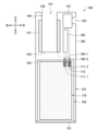
- 2 is a diagram showing an internal configuration of a suction device according to the embodiment of the present invention;
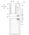
- FIG. 2 is a diagram showing an internal configuration of a suction device according to the embodiment of the present invention;
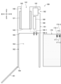
- FIG. 13 is a diagram illustrating a schematic configuration of a suction device according to a first modified example.
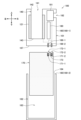
- FIG. 13 is a diagram illustrating a schematic configuration of a suction device according to a second modified example.
- elements having substantially the same functional configuration may be distinguished by assigning an index containing different letters or numbers after the same reference numeral.
- multiple elements having substantially the same functional configuration may be distinguished as necessary, such as devices 1-1 and 1-2.
- only the same reference numeral may be assigned.
- devices 1-1 and 1-2 they may simply be referred to as device 1.
- the inhalation device is a device that generates a substance to be inhaled by a user.
- the substance generated by the inhalation device is described as an aerosol.
- the substance generated by the inhalation device may be a gas.
- FIG. 1 is a schematic diagram showing an example of the configuration of a suction device.
- the suction device 100 includes a power supply unit 111, a sensor unit 112, a notification unit 113, a memory unit 114, a communication unit 115, a control unit 116, a heating unit 121, a storage unit 140, and a heat insulating unit 144.
- the power supply unit 111 stores power.
- the power supply unit 111 supplies power to each component of the suction device 100 under the control of the control unit 116.
- the power supply unit 111 may be configured, for example, by a rechargeable battery such as a lithium ion secondary battery.
- the sensor unit 112 acquires various information related to the suction device 100.
- the sensor unit 112 is configured with a pressure sensor such as a condenser microphone, a flow sensor, or a temperature sensor, and acquires values associated with suction by the user.
- the sensor unit 112 is configured with an input device such as a button or switch that accepts information input from the user.
- the notification unit 113 notifies the user of information.
- the notification unit 113 is composed of, for example, a light-emitting device that emits light, a display device that displays an image, a sound output device that outputs sound, or a vibration device that vibrates.
- the storage unit 114 stores various information for the operation of the suction device 100.
- the storage unit 114 is configured, for example, from a non-volatile storage medium such as a flash memory.
- the communication unit 115 is a communication interface capable of performing communication conforming to any wired or wireless communication standard.
- Such communication standards may include, for example, standards using Wi-Fi (registered trademark), Bluetooth (registered trademark), BLE (Bluetooth Low Energy (registered trademark)), NFC (Near Field Communication), or LPWA (Low Power Wide Area).
- the control unit 116 functions as an arithmetic processing unit and a control unit, and controls the overall operation of the suction device 100 in accordance with various programs.
- the control unit 116 is realized by an electronic circuit such as a CPU (Central Processing Unit) or a microprocessor.
- the storage section 140 has an internal space 141 and holds the stick-shaped substrate 150 while storing a part of the stick-shaped substrate 150 in the internal space 141.
- the storage section 140 has an opening 142 that connects the internal space 141 to the outside, and stores the stick-shaped substrate 150 inserted into the internal space 141 through the opening 142.
- the storage section 140 is a cylindrical body with the opening 142 and the bottom 143 as the bottom surface, and defines a columnar internal space 141.
- An air flow path that supplies air to the internal space 141 is connected to the storage section 140.
- An air inlet hole which is an air inlet to the air flow path, is arranged, for example, on the side of the suction device 100.
- An air outlet hole which is an air outlet from the air flow path to the internal space 141, is arranged, for example, on the bottom 143.
- the stick-type substrate 150 includes a substrate portion 151 and a mouthpiece portion 152.
- the substrate portion 151 includes an aerosol source.
- the aerosol source includes a flavor component derived from tobacco or non-tobacco.
- the aerosol source may include a medicine.
- the aerosol source may be, for example, a liquid such as a polyhydric alcohol such as glycerin and propylene glycol, and water, which includes a flavor component derived from tobacco or non-tobacco, or may be a solid which includes a flavor component derived from tobacco or non-tobacco.
- the stick-type substrate 150 When the stick-type substrate 150 is held in the storage portion 140, at least a portion of the substrate portion 151 is stored in the internal space 141, and at least a portion of the mouthpiece portion 152 protrudes from the opening 142.
- the suction mouth portion 152 protruding from the opening 142 in their mouth and inhales air flows into the internal space 141 via an air flow path (not shown) and reaches the user's mouth together with the aerosol generated from the base portion 151.
- the heating unit 121 generates aerosol by heating the aerosol source and atomizing the aerosol source.
- the heating unit 121 is configured in a film shape and is arranged to cover the outer periphery of the storage unit 140.
- the heating unit 121 generates heat, the substrate unit 151 of the stick-shaped substrate 150 is heated from the outer periphery, and an aerosol is generated.
- the heating unit 121 generates heat when power is supplied from the power supply unit 111.
- power may be supplied when the sensor unit 112 detects that the user has started inhaling and/or that specific information has been input. Power supply may be stopped when the sensor unit 112 detects that the user has stopped inhaling and/or that specific information has been input.
- the insulating section 144 prevents heat transfer from the heating section 121 to other components.
- the insulating section 144 is made of a vacuum insulating material or an aerogel insulating material.
- the configuration of the suction device 100 is not limited to the above, and various configurations such as those exemplified below are possible.
- the heating unit 121 may be configured in a blade shape and disposed so as to protrude from the bottom 143 of the storage unit 140 into the internal space 141. In that case, the blade-shaped heating unit 121 is inserted into the substrate 151 of the stick-shaped substrate 150 and heats the substrate 151 of the stick-shaped substrate 150 from the inside. As another example, the heating unit 121 may be disposed so as to cover the bottom 143 of the storage unit 140. Furthermore, the heating unit 121 may be configured as a combination of two or more of a first heating unit that covers the outer periphery of the storage unit 140, a blade-shaped second heating unit, and a third heating unit that covers the bottom 143 of the storage unit 140.
- the storage unit 140 may include an opening/closing mechanism such as a hinge that opens and closes a portion of the outer shell that forms the internal space 141. The storage unit 140 may then open and close the outer shell to accommodate the stick-shaped substrate 150 inserted into the internal space 141 while clamping it.
- the heating unit 121 may be provided at the clamping location in the storage unit 140, and may heat the stick-shaped substrate 150 while pressing it.
- the means for atomizing the aerosol source is not limited to heating by the heating unit 121.
- the means for atomizing the aerosol source may be induction heating.
- the suction device 100 has at least an electromagnetic induction source such as a coil that generates a magnetic field, instead of the heating unit 121.
- a susceptor that generates heat by induction heating may be provided in the suction device 100, or may be included in the stick-shaped substrate 150.
- FIG. 2 is a perspective view showing an example of the external configuration of the suction device 100 according to this embodiment.
- Figures 3 and 4 are diagrams that generally show the internal configuration of the suction device 100 according to this embodiment.
- the suction device 100 may be configured as a straight cylinder with an oval cross section.
- the suction device 100 is configured to a size that can be held by a user, and is used while being held by the user.
- the surface of the suction device 100 may be provided with a user interface, such as buttons for inputting operating instructions to the suction device 100, or a display that displays the operating status of the suction device 100.
- the direction in which the stick-shaped substrate 150 is inserted into and removed from the storage section 140 is also referred to as the up-down direction.
- the up-down direction corresponds to the longitudinal direction of the suction device 100.
- the longitudinal direction of the cross section of the suction device 100 is also referred to as the left-right direction, and the lateral direction is also referred to as the front-rear direction.
- the up-down direction is an example of a first direction.
- the left-right direction is an example of a second direction that is perpendicular to the up-down direction.
- the suction device 100 has a housing 160, a cover portion 161, a battery chamber 162, a plurality of electrical contacts 166 (166-1, 166-2), a control circuit 180, a charging circuit 181, and a charging terminal 182.
- a battery pack 170 is detachably attached to the suction device 100.
- the control circuit 180 and the charging circuit 181 correspond to the control unit 116 shown in Figure 1.
- the battery pack 170 corresponds to the power supply unit 111 shown in Figure 1.
- the battery pack 170 is a rechargeable battery that is configured to be detachable from the suction device 100.
- the battery pack 170 has multiple electrodes 171 (171-1 and 171-2).
- the electrode 171-1 may be a positive electrode
- the electrode 171-2 may be a negative electrode.
- the portion of the suction device 100 excluding the battery pack 170 is also referred to as the main body 101.
- the housing 160 constitutes the outermost shell of the suction device 100.
- an opening 142 is provided on the top surface of the housing 160.
- the stick-shaped substrate 150 is inserted into and removed from the storage section 140 through the opening 142.
- the opening 142 is an example of a first opening provided at one end of the housing 160 in the vertical direction.
- an opening 164 is provided on the bottom surface of the housing 160.
- the opening 164 is an example of a second opening provided at the other end of the housing 160 in the vertical direction.
- the battery chamber 162 removably houses the battery pack 170. More specifically, the battery chamber 162 has an internal space 163, and houses the battery pack 170 in the internal space 163.
- the opening 164 connects the internal space 163 to the outside.
- the battery pack 170 is inserted into and removed from the battery chamber 162 through the opening 164.
- the lid 161 opens and closes the opening 164.
- the opening and closing of the opening 164 by the lid 161 may be achieved by a hinge mechanism.
- Figure 3 shows a state in which the lid 161 closes the opening 164 and the battery pack 170 is housed in the battery chamber 162.
- Figure 4 shows a state in which the lid 161 opens the opening 164 and the battery pack 170 has been removed from the battery chamber 162.
- the main body 101 of the suction device 100 has multiple electrical contacts 166 (166-1 and 166-2).
- the electrical contacts 166 are a power interface between the battery pack 170 and the components within the main body 101 of the suction device 100.
- the electrical contacts 166 are connected to the heating section 121 and the charging circuit 181 via conductors, and transmit and receive power therebetween. Electrical connections with other components are omitted from the illustration in Figures 3 and 4.
- each of the electrical contacts 166 is detachably connected to each of the electrodes 171 of the battery pack 170.
- the electrical contacts 166 are configured to protrude downward from the upper surface 165 of the battery chamber 162.
- each of the electrical contacts 166 is connected to each of the electrodes 171 (171-1 and 171-2) of the battery pack 170.
- the electrical contact 166-1 is connected to the electrode 171-1
- the electrical contact 166-2 is connected to the electrode 171-2. This allows power to be supplied from the battery pack 170 to other components in the main body 101 of the suction device 100.
- the connection between each of the electrical contacts 166 and each of the electrodes 171 of the battery pack 170 is released.
- the electrical contact 166 may be made of an elastic body such as a wire spring or a leaf spring.
- the elastic body serving as the electrical contact 166 is pushed upward while in contact with the electrode 171, exerting a downward elastic force.
- the electrical contact 166 and the electrode 171 can be brought into stronger contact with each other when the battery pack 170 is housed in the battery chamber 162. As a result, it is possible to reduce the contact resistance at the connection point between the electrical contact 166 and the electrode 171.
- the electrical contact 166 is preferably made of a heat-resistant alloy.
- heat-resistant alloys include phosphor bronze and Corson alloy.
- An offset position here refers to a position that is separated or does not overlap.
- the electrical contacts 166 are located on the opening 142 side of the battery pack 170 in the vertical direction when the electrical contacts 166 and the electrodes 171 of the battery pack 170 are connected. That is, none of the electrical contacts 166 are located below the battery pack 170 housed in the battery chamber 162, but only above it.
- the distance between the electrical contacts 166 and the components e.g., the heating unit 121 and the charging circuit 181) that are the power supply destination of the battery pack 170 can be minimized. Therefore, it is possible to suppress power loss during the transmission from the battery pack 170 to the power supply destination.
- this configuration has various advantages compared to the case where the electrical contacts 166 are provided on both the top and bottom of the battery pack 170.
- the battery pack 170 has a partition 173 that separates the electrodes 171-1 and 171-2. Specifically, the electrodes 171 are embedded in a number of recesses 172 (172-1 and 172-2) provided on the top surface of the battery pack 170. A partition 173 is provided between adjacent recesses 172. With this configuration, when the battery pack 170 is housed in the battery chamber 162, each of the electrical contacts 166 fits completely into each of the recesses 172 and is separated from one another by the partition 173. As a result, it is possible to prevent short circuits.
- the battery chamber 162 may be configured in a shape that circumscribes the battery pack 170.
- the battery pack 170 be configured in a shape that is difficult to rotate around the vertical axis while housed in the battery chamber 162, such as an elliptical cylinder or a rectangular cylinder. With such a configuration, it is possible to limit the rotation of the battery pack 170 within the battery chamber 162, and easily maintain the connection between the electrical contacts 166 and the electrodes 171.
- the control circuit 180 controls the power supply from the battery pack 170 to the heating unit 121.
- the control circuit 180 can control the power supply from the battery pack 170 to the heating unit 121 based on a heating profile.
- the heating profile is control information for controlling the temperature at which the aerosol source is heated, and is, for example, information indicating the time series transition of the target value of the temperature of the heating unit 121.
- the control circuit 180 controls the power supply to the heating unit 121 so that the temperature of the heating unit 121 transitions as specified in the heating profile.
- the heating profile is typically designed to optimize the flavor experienced by the user when the user inhales the aerosol generated from the stick-shaped substrate 150. Therefore, by controlling the operation of the heating unit 121 based on the heating profile, the flavor experienced by the user can be optimized.
- the temperature control of the heating section 121 can be achieved, for example, by known feedback control.
- the feedback control may be, for example, PID control (Proportional-Integral-Differential Controller).
- the control section 116 can supply power from the battery pack 170 to the heating section 121 in the form of pulses using pulse width modulation (PWM) or pulse frequency modulation (PFM). In this case, the control section 116 can control the temperature of the heating section 121 by adjusting the duty ratio of the power pulse in the feedback control.
- PWM pulse width modulation
- PFM pulse frequency modulation
- the temperature of the heating section 121 can be quantified, for example, by measuring or estimating the electrical resistance value of the heating section 121 (more precisely, the heating resistor that constitutes the heating section 121). This is because the electrical resistance value of the heating resistor changes depending on the temperature.
- the electrical resistance value of the heating resistor can be estimated, for example, by measuring the amount of voltage drop in the heating resistor.
- the amount of voltage drop in the heating resistor can be measured by a voltage sensor that measures the potential difference applied to the heating resistor.
- the temperature of the heating section 121 can be measured by a temperature sensor such as a thermistor installed near the heating section 121.
- the charging circuit 181 controls the charging of the battery pack 170.
- the charging circuit 181 supplies power supplied from an external power source via the charging terminal 182 to the battery pack 170. At that time, the charging circuit 181 controls the voltage and current.
- the charging circuit 181 may control the charging of the battery pack 170 while detecting the temperature of the battery pack 170.
- the temperature of the battery pack 170 may be detected by a temperature sensor such as a thermistor.
- the thermistor for detecting the temperature of the battery pack 170 may be built into the battery pack 170. Alternatively, the thermistor for detecting the temperature of the battery pack 170 may be disposed on the inner wall of the battery chamber 162 in a position that contacts the battery pack 170 housed in the battery chamber 162.
- the charging terminal 182 is an interface between the charging circuit 181 and an external power source that supplies power to charge the battery pack 170 housed in the battery chamber 162.
- the charging terminal 182 may be a USB (Universal Serial Bus) port.
- a USB cable may be connected to the charging terminal 182, and power may be supplied from an outlet via the USB cable.
- the charging terminal 182 be provided at one end in the left-right direction of the housing 160.
- the heating unit 121 is provided on the left side, it is desirable that the charging terminal 182 be provided at the right end, which is the end opposite the heating unit 121. With this configuration, it is possible to most effectively suppress the transfer of heat from the heating unit 121 to the charging terminal 182.
- the charging circuit 181 and the charging terminal 182 are located closer to the opening 142 than the battery pack 170 in the vertical direction when the multiple electrical contacts 166 are connected to the multiple electrodes 171 of the battery pack 170.
- neither the charging circuit 181 nor the charging terminal 182 are located below the battery pack 170 housed in the battery chamber 162, but only above it.
- the charging terminal 182 can be located near the charging circuit 181. This makes it possible to suppress power loss during power transmission from the charging terminal 182 to the charging circuit 181.
- the opening 164 is provided at the lower end of the suction device 100, and the opening 164 is opened and closed by the lid portion 161.
- the configuration that allows the battery pack 170 to be replaced is not limited to this example.
- the opening 164 and the lid portion 161 may be provided on the side of the suction device 100, and the battery pack 170 may be inserted and removed in the left-right direction or the front-back direction.
- Other configuration examples will be described with reference to Figs. 5 and 6. Below, differences from the configuration examples described in the above embodiment will be mainly described, and similar points will not be described.
- FIG. 5 is a diagram showing a schematic configuration of the suction device 100 according to the first modified example.
- the housing 160 may be composed of an upper housing 160-1 and a lower housing 160-2 that are detachable from each other.
- the connection between the upper housing 160-1 and the lower housing 160-2 may be realized by fitting or screwing, etc.
- the upper housing 160-1 is provided with a heating section 121, a storage section 140, a plurality of electrical contacts 166, a control circuit 180, a charging circuit 181, and a charging terminal 182.
- the main body 101 in this modified example is a part of the suction device 100 that is included in the upper housing 160-1.
- Each of the plurality of electrical contacts 166 is configured to protrude downward from a bottom surface 167 of the upper housing 160-1.
- the lower housing 160-2 is configured as a bottomed cylindrical body having a battery chamber 162.
- An opening 164 is provided at the top of the lower housing 160-2, which communicates the internal space 163 of the battery chamber 162 with the outside.
- the upper housing 160-1 and the battery pack 170 are connected in a state in which each of the electrical contacts 166 is connected to each of the electrodes 171. Thereafter, the upper housing 160-1 and the lower housing 160-2 are connected to accommodate the battery pack 170 in the battery chamber 162, thereby forming the suction device 100.
- the lower housing 160-2 is removed from the upper housing 160-1 to expose the battery pack 170, and then the battery pack 170 is removed.
- the battery pack 170 is replaced in a state in which the upper housing 160-1 and the lower housing 160-2 are separated. Therefore, it is possible to make the replacement work of the battery pack 170 easier.
- the entire lower housing 160-2 can support the weight of the battery pack 170. Therefore, compared to the above embodiment in which only the lid portion 161 supports the weight of the battery pack 170, damage can be prevented.
- FIG. 6 is a diagram showing a schematic configuration of the suction device 100 according to the second modified example.
- the battery pack 170 is attached to and detached from the main body 101 in an exposed state without being stored.
- the housing 160 according to this modified example is provided with the heating section 121, the storage section 140, a plurality of electrical contacts 166, a control circuit 180, a charging circuit 181, and a charging terminal 182.
- the main body 101 in this modified example is a part of the suction device 100 that is included in the housing 160.
- the connection between the housing 160 and the battery pack 170 can be realized by a screw connection or a similar.
- Each of the plurality of electrical contacts 166 is configured to protrude downward from the bottom surface 168 of the housing 160.
- the housing 160 and the battery pack 170 are connected with each of the plurality of electrical contacts 166 connected to each of the plurality of electrodes 171, thereby forming the suction device 100. According to this modified example, it is possible to make the battery pack 170 replacement work easier.
- the inhalation device 100 is an example of an aerosol generating system that generates an aerosol by heating an aerosol source.
- the battery pack 170 is configured to be detachable from the inhalation device 100.
- the inhalation device 100 excluding the battery pack 170 may be regarded as an aerosol generating system, or the entire inhalation device 100 including the battery pack 170 may be regarded as an aerosol generating system.
- a combination of the inhalation device 100 and the stick-shaped substrate 150 may be regarded as an aerosol generating system.
- the heating unit 121 described above is an example of a load that generates energy to heat the aerosol source contained in the stick-shaped substrate 150 housed in the housing unit 140.
- an electromagnetic induction source such as an induction coil corresponds to the load.
- the lid portion 161 may be configured to be removable from the housing 160, or the lid portion 161 may be detachably connected to the housing 160.
- the connection between the housing 160 and the lid portion 161 may be achieved by a screw engagement, a threaded engagement, or the like.
- connection between the electrical contact 166 and the electrode 171 is realized by configuring the electrical contact 166 as an elastic body, but the present disclosure is not limited to such an example.
- the electrode 171 may be configured as an elastic body together with or instead of the electrical contact 166.
- the electrical contact 166 and/or the electrode 171 may be configured as a pogo pin.
- the electrical contact 166 is made of a heat-resistant alloy
- the present disclosure is not limited to such an example.
- the electrode 171 may be made of a heat-resistant alloy.
- the suction device 100 may have a power receiving device for receiving non-contact power supply such as a power receiving coil. It is desirable for the power receiving device to be disposed in a position similar to the position of the charging terminal 182 described above.
- a partition that separates the multiple electrical contacts 166 may be provided on the upper surface 165 of the battery chamber 162.
- the suction device 100 may have a function of detecting the opening and closing of the lid portion 161. Such a function may be realized, for example, by a capacitance sensor or a magnetic sensor.
- the control unit 116 may control the operation of the suction device 100 based on the opening and closing of the lid portion 161. As an example, the control unit 116 may execute the operation of the suction device 100, such as heating by the heating unit 121, limited to the state in which the lid portion 161 is closed. When the lid portion 161 is in a half-fitted state, that is, in a half-closed state, the contact between the electrode 171 and the electrical contact 166 may be incomplete.
- the series of processes performed by each device described in this specification may be realized using software, hardware, or a combination of software and hardware.
- the programs constituting the software are stored in advance, for example, in a recording medium (more specifically, a non-transient storage medium readable by a computer) provided inside or outside each device.
- Each program is loaded into a RAM when executed by a computer that controls each device described in this specification, and executed by a processing circuit such as a CPU.
- the recording medium is, for example, a magnetic disk, an optical disk, a magneto-optical disk, a flash memory, etc.
- the computer program may be distributed, for example, via a network without using a recording medium.
- the computer may be an application-specific integrated circuit such as an ASIC, a general-purpose processor that executes functions by reading a software program, or a computer on a server used in cloud computing.
- ASIC application-specific integrated circuit
- ASIC application-specific integrated circuit
- CPU central processing unit
- CPU central processing unit
- server a server used in cloud computing.
- the series of processes performed by each device described in this specification may be distributed and processed by multiple computers.
- a first opening is provided at one end of the housing in a first direction; a housing portion that houses a base material to be inserted or removed through the first opening; A load that generates energy for heating an aerosol source contained in the substrate contained in the container; and a plurality of electrical contacts detachably connected to the positive and negative electrodes of a battery pack that supplies power to the load; a control circuit for controlling power supply from the battery pack to the load; Equipped with the plurality of electrical contacts are located closer to the first opening than the battery pack in the first direction when the plurality of electrical contacts are connected to the positive electrode and the negative electrode of the battery pack. Aerosol generation systems.
- the electrical contacts are offset from the load in a second direction perpendicular to the first direction.
- the electrical contacts are made of a heat-resistant alloy.
- the battery pack has a partition wall that separates the positive electrode and the negative electrode.
- the aerosol generation system comprises: a charging circuit for controlling charging of the battery pack; a charging terminal which is an interface between an external power source for supplying power for charging the battery pack and the charging circuit; Further equipped with the charging circuit and the charging terminal are located closer to the first opening than the battery pack in the first direction when the plurality of electrical contacts are connected to the positive electrode and the negative electrode of the battery pack.
- the charging terminal is provided at a position offset from the load in a second direction perpendicular to the first direction.
- the charging terminal is provided at one end of the housing in the second direction.
- the aerosol generation system comprises: a second opening provided at the other end of the housing in the first direction; a battery chamber that houses the battery pack that is inserted and removed through the second opening; A cover portion that opens and closes the second opening; Further comprising: The aerosol generation system described in any one of (1) to (7).
- the aerosol generating system further comprises the substrate.
- the aerosol generating system further comprises the battery pack.
- Suction device 101 Main body 111 Power supply unit 112 Sensor unit 113 Notification unit 114 Memory unit 115 Communication unit 116 Control unit 121 Heating unit 140 Storage unit 141 Internal space 142 Opening 143 Bottom 150 Stick-shaped substrate 151 Substrate unit 152 Suction port unit 160 Housing (160-1: upper housing, 160-2: lower housing) 161 Lid 162 Battery chamber 163 Internal space 164 Opening 165 Top surface 166 Electrical contact 167 Bottom surface 168 Bottom surface 170 Battery pack 171 Electrode 172 Recess 173 Partition 180 Control circuit 181 Charging circuit 182 Charging terminal
Landscapes
- Engineering & Computer Science (AREA)
- Power Engineering (AREA)
- Battery Mounting, Suspending (AREA)
Priority Applications (5)
| Application Number | Priority Date | Filing Date | Title |
|---|---|---|---|
| JP2024572799A JPWO2024157468A1 (cg-RX-API-DMAC7.html) | 2023-01-27 | 2023-01-27 | |
| EP23918428.6A EP4646957A1 (en) | 2023-01-27 | 2023-01-27 | Aerosol generation system |
| PCT/JP2023/002684 WO2024157468A1 (ja) | 2023-01-27 | 2023-01-27 | エアロゾル生成システム |
| CN202380091534.7A CN120475918A (zh) | 2023-01-27 | 2023-01-27 | 气溶胶产生系统 |
| KR1020257023394A KR20250122505A (ko) | 2023-01-27 | 2023-01-27 | 에어로졸 생성 시스템 |
Applications Claiming Priority (1)
| Application Number | Priority Date | Filing Date | Title |
|---|---|---|---|
| PCT/JP2023/002684 WO2024157468A1 (ja) | 2023-01-27 | 2023-01-27 | エアロゾル生成システム |
Publications (1)
| Publication Number | Publication Date |
|---|---|
| WO2024157468A1 true WO2024157468A1 (ja) | 2024-08-02 |
Family
ID=91970092
Family Applications (1)
| Application Number | Title | Priority Date | Filing Date |
|---|---|---|---|
| PCT/JP2023/002684 Ceased WO2024157468A1 (ja) | 2023-01-27 | 2023-01-27 | エアロゾル生成システム |
Country Status (5)
| Country | Link |
|---|---|
| EP (1) | EP4646957A1 (cg-RX-API-DMAC7.html) |
| JP (1) | JPWO2024157468A1 (cg-RX-API-DMAC7.html) |
| KR (1) | KR20250122505A (cg-RX-API-DMAC7.html) |
| CN (1) | CN120475918A (cg-RX-API-DMAC7.html) |
| WO (1) | WO2024157468A1 (cg-RX-API-DMAC7.html) |
Cited By (1)
| Publication number | Priority date | Publication date | Assignee | Title |
|---|---|---|---|---|
| WO2026140101A1 (ja) * | 2024-12-25 | 2026-07-02 | 日本たばこ産業株式会社 | 香味吸引器および香味吸引システム |
Citations (6)
| Publication number | Priority date | Publication date | Assignee | Title |
|---|---|---|---|---|
| JPH0927348A (ja) * | 1995-07-10 | 1997-01-28 | Sony Corp | バッテリー充電装置 |
| WO2015038981A2 (en) | 2013-09-13 | 2015-03-19 | Nicodart, Inc. | Programmable electronic vaporizing apparatus and smoking cessation system |
| JP2018129267A (ja) * | 2017-02-10 | 2018-08-16 | ソニー株式会社 | バッテリー及び接続機器 |
| CN111035075A (zh) * | 2020-01-14 | 2020-04-21 | 东莞市麦斯莫科电子科技有限公司 | 模块化电子烟 |
| JP2020521455A (ja) * | 2017-05-26 | 2020-07-27 | ケーティー・アンド・ジー・コーポレーション | エアロゾル生成装置の充電システム |
| CN113812683A (zh) * | 2021-08-20 | 2021-12-21 | 河南中烟工业有限责任公司 | 可更换电池的外围加热器具 |
-
2023
- 2023-01-27 WO PCT/JP2023/002684 patent/WO2024157468A1/ja not_active Ceased
- 2023-01-27 CN CN202380091534.7A patent/CN120475918A/zh active Pending
- 2023-01-27 EP EP23918428.6A patent/EP4646957A1/en active Pending
- 2023-01-27 JP JP2024572799A patent/JPWO2024157468A1/ja active Pending
- 2023-01-27 KR KR1020257023394A patent/KR20250122505A/ko active Pending
Patent Citations (6)
| Publication number | Priority date | Publication date | Assignee | Title |
|---|---|---|---|---|
| JPH0927348A (ja) * | 1995-07-10 | 1997-01-28 | Sony Corp | バッテリー充電装置 |
| WO2015038981A2 (en) | 2013-09-13 | 2015-03-19 | Nicodart, Inc. | Programmable electronic vaporizing apparatus and smoking cessation system |
| JP2018129267A (ja) * | 2017-02-10 | 2018-08-16 | ソニー株式会社 | バッテリー及び接続機器 |
| JP2020521455A (ja) * | 2017-05-26 | 2020-07-27 | ケーティー・アンド・ジー・コーポレーション | エアロゾル生成装置の充電システム |
| CN111035075A (zh) * | 2020-01-14 | 2020-04-21 | 东莞市麦斯莫科电子科技有限公司 | 模块化电子烟 |
| CN113812683A (zh) * | 2021-08-20 | 2021-12-21 | 河南中烟工业有限责任公司 | 可更换电池的外围加热器具 |
Non-Patent Citations (1)
| Title |
|---|
| See also references of EP4646957A1 |
Cited By (1)
| Publication number | Priority date | Publication date | Assignee | Title |
|---|---|---|---|---|
| WO2026140101A1 (ja) * | 2024-12-25 | 2026-07-02 | 日本たばこ産業株式会社 | 香味吸引器および香味吸引システム |
Also Published As
| Publication number | Publication date |
|---|---|
| JPWO2024157468A1 (cg-RX-API-DMAC7.html) | 2024-08-02 |
| EP4646957A1 (en) | 2025-11-12 |
| KR20250122505A (ko) | 2025-08-13 |
| CN120475918A (zh) | 2025-08-12 |
Similar Documents
| Publication | Publication Date | Title |
|---|---|---|
| JP7712336B2 (ja) | 低温電子気化デバイスおよびその方法 | |
| JP7562726B2 (ja) | 過熱防止を備えたエアロゾル発生システム | |
| TWI643565B (zh) | 電源組合、非燃燒型香味吸嚐器及非燃燒型香味吸嚐系統 | |
| EP3838004A1 (en) | Charging device and smoking substitute kit | |
| US20230114675A1 (en) | Display device, inhaler device, display method, and program | |
| EP4101321A1 (en) | Inhaling device, control method, and program | |
| JP7685067B2 (ja) | エアロゾル生成装置の通知制御装置、エアロゾル生成装置の通知制御方法、及びエアロゾル生成装置の制御プログラム | |
| US20240206553A1 (en) | Aerosol-generating device | |
| WO2024201777A1 (ja) | エアロゾル生成システム | |
| CN115697104A (zh) | 气溶胶生成装置的电源单元 | |
| US20240206562A1 (en) | Aerosol-generating device | |
| JP7493049B2 (ja) | エアロゾル生成装置 | |
| JP2023535401A (ja) | エアロゾル発生装置用ケース | |
| JP2021534729A (ja) | 霧化器及びそれを含むカートリッジ | |
| EP4646957A1 (en) | Aerosol generation system | |
| EP4218438A1 (en) | Suction device, control device, and control method | |
| JP7578721B2 (ja) | 吸引装置、制御方法、及びプログラム | |
| US20250009016A1 (en) | Aerosol-generating device | |
| KR20230057597A (ko) | 에어로졸 발생 시스템 | |
| WO2024241484A1 (ja) | エアロゾル生成システム | |
| JP2026509994A (ja) | エアロゾル生成装置 | |
| WO2025062020A1 (en) | Aerosol provision device | |
| WO2025126388A1 (ja) | エアロゾル生成装置の電源ユニット | |
| WO2025126400A1 (ja) | エアロゾル生成装置 | |
| WO2025126391A1 (ja) | エアロゾル生成装置の電源ユニット |
Legal Events
| Date | Code | Title | Description |
|---|---|---|---|
| 121 | Ep: the epo has been informed by wipo that ep was designated in this application |
Ref document number: 23918428 Country of ref document: EP Kind code of ref document: A1 |
|
| ENP | Entry into the national phase |
Ref document number: 2024572799 Country of ref document: JP Kind code of ref document: A |
|
| WWE | Wipo information: entry into national phase |
Ref document number: 2024572799 Country of ref document: JP |
|
| ENP | Entry into the national phase |
Ref document number: 1020257023394 Country of ref document: KR Free format text: ST27 STATUS EVENT CODE: A-0-1-A10-A15-NAP-PA0105 (AS PROVIDED BY THE NATIONAL OFFICE) |
|
| WWE | Wipo information: entry into national phase |
Ref document number: 1020257023394 Country of ref document: KR |
|
| WWE | Wipo information: entry into national phase |
Ref document number: 202380091534.7 Country of ref document: CN |
|
| WWE | Wipo information: entry into national phase |
Ref document number: 2023918428 Country of ref document: EP |
|
| ENP | Entry into the national phase |
Ref document number: 2023918428 Country of ref document: EP Effective date: 20250804 |
|
| WWP | Wipo information: published in national office |
Ref document number: 202380091534.7 Country of ref document: CN |
|
| WWP | Wipo information: published in national office |
Ref document number: 1020257023394 Country of ref document: KR |
|
| NENP | Non-entry into the national phase |
Ref country code: DE |
|
| WWP | Wipo information: published in national office |
Ref document number: 2023918428 Country of ref document: EP |