WO2024157433A1 - 端末、無線通信方法及び無線通信システム - Google Patents
端末、無線通信方法及び無線通信システム Download PDFInfo
- Publication number
- WO2024157433A1 WO2024157433A1 PCT/JP2023/002539 JP2023002539W WO2024157433A1 WO 2024157433 A1 WO2024157433 A1 WO 2024157433A1 JP 2023002539 W JP2023002539 W JP 2023002539W WO 2024157433 A1 WO2024157433 A1 WO 2024157433A1
- Authority
- WO
- WIPO (PCT)
- Prior art keywords
- uci
- bits
- new
- information
- harq
- Prior art date
- Legal status (The legal status is an assumption and is not a legal conclusion. Google has not performed a legal analysis and makes no representation as to the accuracy of the status listed.)
- Ceased
Links
Images




Classifications
-
- H—ELECTRICITY
- H04—ELECTRIC COMMUNICATION TECHNIQUE
- H04W—WIRELESS COMMUNICATION NETWORKS
- H04W72/00—Local resource management
- H04W72/20—Control channels or signalling for resource management
- H04W72/21—Control channels or signalling for resource management in the uplink direction of a wireless link, i.e. towards the network
-
- H—ELECTRICITY
- H04—ELECTRIC COMMUNICATION TECHNIQUE
- H04W—WIRELESS COMMUNICATION NETWORKS
- H04W72/00—Local resource management
- H04W72/50—Allocation or scheduling criteria for wireless resources
- H04W72/51—Allocation or scheduling criteria for wireless resources based on terminal or device properties
Definitions
- This disclosure relates to a terminal, a wireless communication method, and a wireless communication system.
- LTE Long Term Evolution
- UMTS Universal Mobile Telecommunication System
- Successor systems to LTE are also being considered to achieve even wider bandwidth and faster speeds than LTE.
- Examples of successor systems to LTE include systems called LTE-Advanced (LTE-A), Future Radio Access (FRA), 5th generation mobile communication system (5G), 5G plus (5G+), Radio Access Technology (New-RAT), and New Radio (NR).
- Non-Patent Document 1 For 5G, various wireless technologies and network architectures are being considered to meet the requirements of achieving a throughput of 10 Gbps or more while keeping wireless section latency to 1 ms or less (for example, Non-Patent Document 1).
- CG PUSCH Configured Grant Physical Uplink Shared Channel
- Non-Patent Document 2 There are Type 1 CG PUSCH and Type 2 CG PUSCH.
- Release 17 examines Extended Reality (XR), including virtual reality (VR) and mixed reality (MX), and considers XR scenarios, requirements, key performance indicators (KPIs), and evaluation methods.
- Target requirements for XR include capacity, latency (delay), mobility, and energy saving aspects.
- One aspect of the present disclosure is to provide a terminal, a wireless communication method, and a wireless communication system that can appropriately report dynamic indications of unused CG PUSCH occasions to a base station.
- a terminal includes a control unit that determines uplink control information based on the presence or absence of support for transmission of first information indicating an occasion for an unused uplink signal, the support being determined depending on whether the spectrum is unlicensed or a specific control parameter is set, and a transmission unit that transmits the uplink control information.
- FIG. 1 is a diagram illustrating an example of dual connectivity (DC).
- FIG. 13 is a diagram illustrating an example of PUCCH carrier switching. This is a diagram explaining the overview of Type 1 HARQ-ACK CB. This is a diagram explaining the overview of Type 2 HARQ-ACK CB. This figure explains an example of generating a Type 1 HARQ-ACK CB. This figure explains an example of generating a Type 1 HARQ-ACK CB. This figure explains an example of generating a Type 1 HARQ-ACK CB. A figure explaining an example of determining candidate PDSCH receiving opportunities in Step A-2. A diagram illustrating an example of CG PUSCH. FIG.
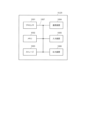
- FIG. 2 is a block diagram showing an example of a configuration of a base station according to the present embodiment.
- 2 is a block diagram showing an example of a configuration of a terminal according to the present embodiment.
- FIG. FIG. 2 is a diagram illustrating an example of a hardware configuration of a base station and a terminal according to an embodiment of the present disclosure.
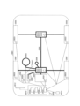
- 1 is a diagram showing an example of a configuration of a vehicle according to an embodiment of the present invention.
- NR Ultra-Reliable and Low Latency Communications
- IIoT Industrial Internet of Things
- HARQ-ACK Hybrid Automatic Repeat request-Acknowledgement
- HARQ-ACK is an example of information regarding an acknowledgment (e.g., acknowledgement) for data received by a terminal.
- PUCCH carrier switching may be referred to by other names, such as carrier switching for control information transmission.
- PUCCH carrier switching is a technology that is applied when a base station communicates through multiple cells. Below, we will explain dual connectivity, which is an example of communication through multiple cells, and PUCCH carrier switching.
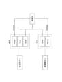
- FIG. 1 is a diagram showing an example of dual connectivity (DC).
- a base station 10-1 may be a Master Node (MN).
- a base station 10-2 may be a Secondary Node (SN).
- DC carriers between different base stations are bundled.
- the base station 10-1 communicates with the terminal 20 via a primary cell (Pcell) and a secondary cell (Scell).
- the terminal 20 establishes an RRC connection with the base station 10-1.
- Uplink Control Information e.g., Uplink Control Information: UCI
- UCI Uplink Control Information
- one carrier under base station 10-2 may be set as a Primary Scell (PScell) and PUCCH transmission may be supported by the PScell.
- PScell Primary Scell
- terminal 20 transmits UCI to base station 10-2 via the PScell.
- the terminal 20 configures an Scell in addition to a Pcell for the base station 10-1.
- the terminal 20 also configures an Scell in addition to a PScell for the base station 10-2.
- the terminal 20 transmits the UCI of each carrier under the base station 10-1 on the PUCCH of the Pcell.
- the terminal 20 also transmits the UCI of each carrier under the base station 10-2 on the PUCCH of the PScell.
- the cell group (CG) under the base station 10-1 may be referred to as a Master Cell-Group (MCG).
- MCG Master Cell-Group
- SCG Secondary Cell-Group
- the terminal 20 may transmit PUCCH via the Pcell, PScell, and/or PUCCH-Scell. In general, it is not expected that the terminal 20 will transmit PUCCH via an Scell other than the Pcell, PScell, and PUCCH-Scell.
- PUCCH carrier switching is being considered as a method to reduce the latency of HARQ-ACK feedback in the Time Division Duplex (TDD) system.
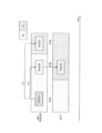
- Figure 2 shows an example of PUCCH carrier switching.
- the base station and the terminal communicate via cell 1 and cell 2.
- cell 1 is a Pcell and cell 2 is an Scell.
- the example of Figure 2 also shows the downlink (DL) slots and uplink (UL) slots in each cell.
- the terminal receives data at timing S101 (receives the Physical Downlink Shared Channel (PDSCH)).
- the terminal attempts to transmit a HARQ-ACK for the data received at S101 at timing S102, but at timing S102, the cell 1 slot is a downlink (DL) slot. Therefore, when the terminal transmits a HARQ-ACK in cell 1, the transmission of the HARQ-ACK is postponed until the timing of transmitting a PUCCH in the uplink (UL) slot (for example, timing S103 in FIG. 2), thereby increasing the latency of the HARQ-ACK transmission.
- the timing of transmitting a PUCCH in an uplink (UL) slot may be referred to as a PUCCH occasion.
- the slot of cell 2 is a UL slot.
- the terminal can transmit a HARQ-ACK for the data received in S101 in the PUCCH occasion at the timing of S102 of cell 2
- the latency of the HARQ-ACK transmission can be reduced.
- URLLC requires low latency, especially in the wireless section.
- 3GPP registered trademark
- PUCCH carrier switching which switches the carrier on which a terminal transmits PUCCH, as an extension of URLLC technology.
- the same timing may mean the exact same timing, or may mean that all or part of a time resource (for example, one or more symbols (which may be a resource with a time unit shorter than a symbol) is the same or overlaps).
- PUCCH carrier switching may refer to a case where a terminal is attempting to transmit PUCCH at a specific transmission timing of a Pcell (which may be a PScell or a PUCCH-Scell), and the slot of the specific transmission timing of the Pcell (which may be a PScell or a PUCCH-Scell) is a DL slot, and the terminal switches the cell from which the PUCCH is transmitted to one of one or more Scells in which the slot with the same timing as the specific transmission timing is a UL slot (in the case of a PScell, an Scell other than the PScell, and in the case of a PUCCH-Scell, an Scell other than the PUCCH-Scell).
- the unit of the specific transmission timing is not limited to a slot.
- the specific transmission timing may be a timing in units of a subframe or a timing in units of a symbol.
- the first method is for the base station to dynamically instruct the terminal on the carrier to transmit the PUCCH.
- the second method is for the base station to semi-statically set the carrier to transmit the PUCCH to the terminal. Note that in the following embodiments, "transmitting PUCCH” and “transmitting PUCCH” may also refer to transmitting uplink control information via PUCCH.
- the terminal may notify the base station of terminal capability information (UE capability) that specifies information regarding the terminal's capabilities regarding PUCCH transmission.
- UE capability terminal capability information
- information indicating whether the terminal supports switching of settings related to the transmission of control information may be specified as the terminal capability information of the terminal.
- Switching of settings related to the transmission of control information may be, for example, switching of resources (e.g., carriers or cells) used for transmitting control information. Switching of resources used for transmitting control information may be referred to as "PUCCH carrier switching.”
- information indicating the application of dynamic PUCCH carrier switching and/or semi-static PUCCH carrier switching may be specified as the terminal capability information of the terminal.
- the configuration operation of quasi-static PUCCH carrier switching may be based on the RRC (Radio Resource Control) setting of the PUCCH cell timing pattern of the PUCCH cell to which the quasi-static PUCCH carrier switching applies.
- the configuration operation of quasi-static PUCCH carrier switching may also be supported between cells of different numerologies.
- PUCCH resources may be configured per UL BWP (Uplink Bandwidth Part) (e.g., per candidate cell and the UL BWP of that candidate cell).
- UL BWP Uplink Bandwidth Part
- the K1 value (offset) from PDSCH to HARQ-ACK may be interpreted based on the numerology of the dynamically instructed target PUCCH cell.
- the control information may be control information for scheduling the PUCCH, such as Downlink control information (DCI).
- DCI Downlink control information
- the numerology may also be considered as slots or Subcarrier Spacing (SCS).
- HARQ-ACK CB HARQ-ACK Codebook
- Type 1 HARQ-ACK CB may also be referred to as semi-static HARQ-ACK CB.
- Type 2 HARQ-ACK CB may also be referred to as dynamic HARQ-ACK CB.
- the terminal may be instructed as to whether to apply Type 1 HARQ-ACK CB or Type 2 HARQ-ACK CB by higher layer signaling, such as RRC (Radio Resource Control).
- RRC Radio Resource Control
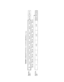
- Fig. 3 is a diagram for explaining an overview of Type 1 HARQ-ACK CB.
- "Scheduled" in Fig. 3 indicates, for example, a slot scheduled by DCI.
- CC indicates Component Carrier.
- Type 1 HARQ-ACK CB the terminal generates a HARQ-ACK bit for the PDSCH regardless of whether a scheduled slot (PDSCH) exists.
- the terminal may set a NACK for an unscheduled PDSCH, as shown in the "HARQ-ACK codebook" in Figure 3.
- Figure 4 is a diagram for explaining the outline of Type 2 HARQ-ACK CB.
- (x, y) in Figure 4 indicates, for example, a slot scheduled by DCI.
- x corresponds to a C-DAI value
- y corresponds to a T-DAI value.
- DAI is an abbreviation for Downlink assignment index.
- DAI indicates, for example, the allocation of a scheduled PDSCH in which HARQ-ACK is bundled in HARQ-ACK CB.
- Type 2 HARQ-ACK CB the terminal generates a HARQ-ACK bit for the scheduled PDSCH.
- the terminal may configure a HARQ-ACK for the scheduled PDSCH as shown in the "HARQ-ACK codebook" in Figure 4.
- C-DAI counts up from 1. For example, in the case of a 2-bit field, C-DAI repeats 1->2->3->0->... C-DAI counts up for each slot at each opportunity to receive DCI for each CC, and even if the slot changes, it counts up from the final value of the previous slot. T-DAI indicates the final value of C-DAI for each slot.
- ⁇ Type 1 HARQ-ACK CB generation> 5 6, and 7 are diagrams for explaining an example of generating a Type 1 HARQ-ACK CB.
- the numerology of the serving cell and the numerology of the PUCCH cell are the same.
- the set of K1 offset from PDSCH to HARQ-ACK is ⁇ 1, 2, 3, 4 ⁇ .
- the numerology of the serving cell and the numerology of the PUCCH cell are different.
- the set of K1 is ⁇ 1, 2, 3, 4, 5 ⁇ .
- the terminal may generate a HARQ-ACK CB based on Step A, Step A-1, Step A-2, and Step B below.
- the terminal determines a HARQ-ACK occasion for a candidate PDSCH reception. For example, the terminal determines the n+4 slot of the PUCCH cell in FIG. 5. For example, the terminal determines the n+5 slot of the PUCCH cell in FIG. 6.
- the terminal determines the PDSCH slot window based on the K1 set. For example, the terminal interprets the K1 set in the numerology of the PUCCH cell and determines the PDSCH slot window shown in the dotted frame in FIG. 5 or FIG. 6.
- Step A-2 The terminal determines candidate PDSCH reception occasions in each slot for each K1. For example, the terminal determines candidate PDSCH reception occasions in each slot as shown in FIG .
- the candidate PDSCH reception opportunities are associated with a set RI (Row index) in the Time Domain Resource Allocation (TDRA) table, as explained in Figure 8.
- RI Range index
- Candidate PDSCH reception opportunities in the TDRA table that overlap with the UL configured by TDD-UL-DL-ConfigurationCommon and TDD-UL-DL-ConfigDedicated are excluded.
- the candidate PDSCH reception opportunities are determined based on specific rules.
- the terminal may determine (generate) a HARQ-ACK (HARQ-ACK information bit, HARQ-ACK CB) for each element of the determined candidate PDSCH receiving opportunity. For example, the terminal may generate the following Type 1 HARQ-ACK CB for a total number of HARQ-ACK information bits O ACK :
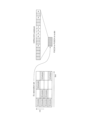
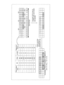
- Figure 8 is a diagram explaining an example of determining candidate PDSCH receiving opportunities in Step A-2.
- the table shown in the upper left of Figure 8 shows an example of TDRA.
- K0 indicates the offset between the DCI slot and the PDSCH slot.
- Start indicates the start symbol in the slot, and Length indicates the length from Start (the number of symbols assigned to the PDSCH).
- Mapping Type relates to the mapping type, which includes information about the symbol that can be set as the start symbol of the PDSCH in the slot.
- the slot format is shown in the upper right corner of Figure 8.
- the last two symbols are semi-statically configured as UL.
- the candidate PDSCH reception opportunities based on RI 0-8 of the TDRA shown in the upper left of Figure 8 are as shown in the upper right of Figure 8. However, the candidate PDSCH reception opportunities in the TDRA table that overlap with the UL are excluded.
- candidate PDSCH reception opportunities in RI2, RI3, and RI8 that overlap with the UL are excluded, and the candidate PDSCH reception opportunities in a certain slot are as shown in the lower right of Figure 8.
- HARQ-ACKs in RI2, RI3, and RI8 are excluded from the generation set of the HARQ-ACK CB.
- the configuration of the CG PUSCH is defined in Rel-16 (for example, Non-Patent Document 2).
- the CG PUSCH includes Type 1 CG PUSCH and Type 2 CG PUSCH.
- Type 1 CG PUSCH The transmission parameters of the Type 1 CG PUSCH are provided by "configuredGrantConfig”, “pusch-Config” and “rrc-ConfiguredUplinkGrant".
- the activation/deactivation of the Type 1 CG PUSCH depends on the RRC-configuration and does not depend on the Downlink Control Information (DCI).
- DCI Downlink Control Information
- Type 2 CG PUSCH The transmission parameters of Type 2 CG PUSCH are provided by "configuredGrantConfig”, "pusch-Config” and "activation DCI". Activation and deactivation of Type 2 CG PUSCH depend on RRC-configuration and DCI. One DCI can activate one CG PUSCH and deactivate multiple CG PUSCHs.
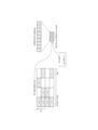
- Figure 9 is a diagram illustrating an example of CG PUSCH.
- the upper layer parameters cg-nrofSlots and cg-nrofPUSCH-InSlot are provided to the terminal.
- cg-nrofSlots indicates the number of consecutive slots allocated in the configured CG period.
- cg-nrofPUSCH-InSlot indicates the number of consecutive PUSCH allocations within a slot.
- the period of the CG PUSCH configuration (the period during which the CG PUSCH is transmitted, for example, the three slots shown in Figure 9) is repeated in the configured CG period.
- the first PUSCH allocation is based on higher layer configuration based on TDRA or TS38.321 in a Type 1 CG PUSCH. Or the first PUSCH allocation is based on UL grant received in DCI in a Type 2 CG PUSCH.
- the remaining PUSCH allocations have the same length and mapping type as the first PUSCH. Each PUSCH is added after the previous PUSCH without gaps.
- TS (technical specification) 38.212 specifies that CG-UCI is transmitted in CG PUSCH when the upper layer parameter "cg-RetransmissionTimer" is set.
- cg-RetransmissionTimer is an example of a specific parameter.
- cg-RetransmissionTimer indicates information about the retransmission timer to be set.
- cg-RetransmissionTimer is set together with the upper layer parameter "harq-ProcID-Offset”.
- cg-RetransmissionTimer is not set for operation in licensed spectrum or is not set simultaneously with the upper layer parameter "harq-ProcID-Offset2".
- licensed spectrum corresponds to a band that requires a license to be used.
- unlicensed spectrum corresponds to a band that does not require a license to be used.
- the fact that the cg-RetransmissionTimer is not set may correspond to the terminal operating in a licensed spectrum.
- the fact that the cg-RetransmissionTimer is set may correspond to the terminal operating not in a licensed spectrum.
- the fact that the terminal operating not in a licensed spectrum may correspond to the terminal operating in an unlicensed spectrum.
- the fact that cg-RetransmissionTimer is set may correspond to the fact that harq-ProcID-Offset is set.
- the fact that cg-RetransmissionTimer is set may correspond to the fact that harq-ProcID-Offset2 is not set, and the fact that cg-RetransmissionTimer is not set may correspond to the fact that harq-ProcID-Offset2 is set.
- the CSI report is divided into two parts.
- the two parts of the CSI report may be referred to as Part 1 CSI report and Part 2 CSI report.
- the two parts of the CSI report may be referred to as CSI part 1 and CSI part 2.
- the HARQ-ACK information may simply be referred to as HARQ-ACK.
- HARQ ACK, CSI part 1 and CSI part 2 may be referred to as HARQ ACK bits, CSI part 1 bits and CSI part 2 bits.
- HARQ ACK bits, CSI part 1 bits and CSI part 2 bits may each be 1 bit of information or multiple bits of information.
- the multiplexed HARQ-ACK, CSI part 1, and CSI part 2 are coded separately.
- the resources for each of the multiplexed HARQ-ACK, CSI part 1, and CSI part 2 are determined separately.
- CG-UCI when transmitting CG PUSCH, CG-UCI is encoded together with HARQ-ACK (e.g., joint encoding). Then, resources are determined for the jointly encoded CG-UCI and HARQ-ACK.
- HARQ-ACK e.g., joint encoding
- a priority is assigned to each UCI in rate matching. For example, when transmitting a CG PUSCH, among the multiplexed HARQ-ACK, CSI part 1, and CSI part 2, the priority of HARQ-ACK is higher than CSI part 1 and CSI part 2, and the priority of CSI part 1 is higher than CSI part 2. In addition, when CG-UCI and HARQ-ACK are coded together, the priority of CG-UCI and HARQ-ACK is higher than CSI part 1 and CSI part 2.
- CG-UCI was introduced along with CG PUSCH in unlicensed spectrum to report information of CG PUSCH.
- a terminal may report a dynamic indication of unused CG PUSCH occasions by UCI.
- the UCI in this consideration may be a CG-UCI or a UCI that is not CG-UCI (e.g., a dedicated UCI).
- an unused CG PUSCH occasion may be described as an unused CG occasion, unused CG opportunity, or unused CG PUSCH opportunity. Note that "unused” may include "unused”.
- a "CG PUSCH occasion” may be referred to as a CG PUSCH transmission occasion.
- a "CG PUSCH configuration" may be referred to as a "CG configuration" or a "CG setting”.
- the first of the two CG-UCIs is the CG-UCI for HARQ process number (HPN), Redundancy version (RV), New data indicator (NDI) and Channel Occupancy Time (COT) sharing information in unlicensed spectrum.
- HPN HARQ process number
- RV Redundancy version
- NDI New data indicator
- COT Channel Occupancy Time
- the CG-UCIs for HPN, RV, NDI and COT sharing information are described in section 6.3.2.1.3 of TS 38.212 and may be referred to below as legacy CG-UCI, "legacy CG-UCI" or "legacy CG-UCI bits".
- the legacy CG-UCI or legacy CG-UCI bits may be one bit of information or multiple bits of information.
- the second of the two CG-UCIs is the CG-UCI introduced to report unused CG occasions.
- the two types of CG-UCI relationships are those between the legacy CG-UCI and the CG-UCI that will be introduced to report unused CG occasions.
- this relationship for example, cases are being considered in which unused CG occasions are indicated by a new CG-UCI and cases in which they are indicated by an existing CG-UCI.
- a CG-UCI that reports an unused CG occasion instruction is a new CG-UCI.
- a CG-UCI that reports an unused CG occasion instruction is described as "new CG-UCI" or "new CG-UCI bits.”
- the new CG-UCI or new CG-UCI bits may be one bit of information or multiple bits of information.
- the new CG-UCI that reports an indication (e.g., a dynamic indication) of an unused CG occasion in the case where the operating frequency band of a wireless communication system including a terminal and a base station is a licensed spectrum and in the case where it is an unlicensed spectrum.
- an indication e.g., a dynamic indication
- ⁇ Consideration item 1 For example, in licensed spectrum, there is room for consideration as to whether or not to support CG-UCI, which reports indications of unused CG occasions (e.g., dynamic indications). Also, if supported, there is room for consideration as to how to multiplex new CG-UCI bits in CG-PUSCH. For example, when multiplexing new CG-UCI bits in CG-PUSCH, there is a matter to consider, such as whether to code them together with existing UCI (e.g., HARQ-ACK, CSI) or to code them separately.
- UCI e.g., HARQ-ACK, CSI
- Consideration item 4 For example, in an unlicensed spectrum, when considering new CG-UCI bits and legacy CG-UCI bits, there is room for consideration as to how the new CG-UCI bits and legacy CG-UCI bits should be multiplexed.
- the terminal may not be able to properly report dynamic indications of unused CG PUSCH occasions to the base station. If the terminal is not able to properly report dynamic indications of unused CG PUSCH occasions to the base station, this may affect the operation of the base station or the terminal, and may also cause problems in terms of resource utilization efficiency.
- this embodiment makes the following proposals.
- Proposal 0 to Proposal 2 are the cases of licensed spectrum and correspond to consideration items 1 and 2 above.
- Proposal 3 to Proposal 5 are the cases of unlicensed spectrum and correspond to consideration items 3 to 5 above.
- Proposal 0 considers support for reporting indications of unused CG occasions (e.g., dynamic indications) by CG-UCI in licensed spectrum.
- Proposal 1 and Proposal 2 consider a method for a terminal to multiplex new CG-UCI in CG PUSCH when multiplexing of other UCIs other than new CG-UCI is considered in CG PUSCH, or when multiplexing is not considered. Note that Proposal 1 considers the case where new CG-UCI is single-part, and Proposal 2 considers the case where new CG-UCI is two-part.
- Proposal 3 considers support for reporting indications of unused CG occasions (e.g., dynamic indications) by CG-UCI in unlicensed spectrum.
- Proposal 4 and Proposal 5 consider a method for a terminal to multiplex new CG-UCI and legacy CG-UCI in a CG PUSCH when multiplexing of UCI other than new CG-UCI is considered in the CG PUSCH, or when multiplexing is not considered. Note that Proposal 4 considers the case where new CG-UCI is single-part, and Proposal 5 considers the case where new CG-UCI is two-part.
- Proposal 0 describes support for reporting of unused CG occasions by CG-UCI in licensed spectrum, which may be replaced by, for example, reporting of unused CG occasions using CG-UCI, and which may correspond to reporting of dynamic indication of unused CG occasions by CG-UCI.
- Option 1 of Proposal 0 does not support a terminal reporting dynamic indication of unused CG occasions by CG-UCI in a licensed spectrum or when cg-RetransmissionTimer is not configured. In other words, Option 1 of Proposal 0 does not support a terminal reporting dynamic indication of unused CG occasions by CG-UCI in a licensed spectrum. Alternatively, Option 1 of Proposal 0 does not support a terminal reporting dynamic indication of unused CG occasions by CG-UCI when cg-RetransmissionTimer is not configured.
- the terminal should not assume that it is configured to report dynamic indication of unused CG occasions by CG-UCI for any CG configuration.
- the terminal does not report dynamic indication of unused CG occasions by CG-UCI in any CG-PUSCH.
- Option 1 of Proposal 0 it may not be necessary to support a terminal reporting dynamic indication of unused CG occasions by CG-UCI in a specific frequency range (e.g., a range referred to as FR (Frequency Range) 1 or FR2-1) and/or a specific SCS (e.g., any SCS of 15 kHz / 30 kHz / 60 kHz / 120 kHz).
- FR Frequency Range
- this variation may support a terminal reporting dynamic indication of unused CG occasions by CG-UCI in a frequency range other than the specific frequency range and/or an SCS other than the specific SCS.
- Option 2 of Proposal 0 supports the terminal to report dynamic indication of unused CG occasions by CG-UCI in a licensed spectrum or when cg-RetransmissionTimer is not configured.
- Option 2 of Proposal 0 supports the terminal to report dynamic indication of unused CG occasions by CG-UCI in a licensed spectrum.
- Option 2 of Proposal 0 supports the terminal to report dynamic indication of unused CG occasions by CG-UCI when cg-RetransmissionTimer is not configured.
- the terminal may assume that it is configured to report dynamic indication of unused CG occasions via CG-UCI for any CG configuration.
- the terminal may report dynamic indication of unused CG occasions by CG-UCI in any CG-PUSCH.
- a terminal may support reporting dynamic indication of unused CG occasions via CG-UCI in a specific frequency range (e.g., the ranges designated FR1, FR2-1) and/or a specific SCS (e.g., any SCS of 15 kHz / 30 kHz / 60 kHz / 120 kHz).
- a specific frequency range e.g., the ranges designated FR1, FR2-1
- a specific SCS e.g., any SCS of 15 kHz / 30 kHz / 60 kHz / 120 kHz.
- the presence or absence of support for reporting dynamic indication of unused CG occasions by CG-UCI is specified depending on whether the operating frequency band is a licensed spectrum or whether cg-RetransmissionTimer is not set.
- the terminal decides whether or not to report dynamic indication of unused CG occasions by CG-UCI based on the presence or absence of support specified depending on, for example, whether the operating frequency band is a licensed spectrum or whether cg-RetransmissionTimer is not set, determines UCI depending on the decision, and transmits UCI. This allows dynamic indication of unused CG occasions to be reported appropriately.
- Proposal 1 is based on the following two assumptions: - It is a licensed spectrum or cg-RetransmissionTimer is not configured. - The CG-UCI for indicating an unused CG PUSCH occasion is a single-part CG-UCI.
- new CG-UCI bits single-part CG-UCI information (e.g., information bits or information parts) for indicating unused CG PUSCH occasions.
- new CG-UCI bits is not limited to being for indicating unused CG PUSCH occasions.
- the terminal generates new CG-UCI bits for indicating unused CG PUSCH occasions.
- the method for generating new CG-UCI bits is not particularly limited.
- new CG-UCI bits may be generated in the following manner.
- ⁇ Production method 1> In generation method 1, the following options are considered regarding the method for the terminal to dynamically indicate an unused CG PUSCH occasion by CG-UCI.
- the terminal dynamically indicates unused CG PUSCH occasions by a CG-UCI (hereinafter, a new CG-UCI) different from the existing CG-UCI.
- a new CG-UCI may be a CG-UCI that can have new CG-UCI bits.
- the terminal generates new CG-UCI bits for indicating unused CG PUSCH occasions in the new CG-UCI.
- the CG PUSCH can contain two CG-UCIs.
- the terminal dynamically indicates the unused CG PUSCH occasion by the existing CG-UCI.
- the new UCI field may be a CG-UCI that can have new CG-UCI bits.
- the terminal generates new CG-UCI bits for indicating the unused CG PUSCH occasion in the new UCI field in the existing CG-UCI.
- the terminal transmits up to one CG-UCI along with the CG PUSCH.
- Whether or not a new CG-UCI exists as in option 1 of generation method 1 described above, or whether or not a new CG-UCI field exists in an existing CG-UCI as in option 2, may be determined (or discriminated) as in the following example.
- option 2 whether a new CG-UCI exists or whether a new CG-UCI field exists in an existing CG-UCI is determined by a higher layer configuration (e.g., an RRC configuration and/or a dynamic indication).
- a higher layer configuration e.g., an RRC configuration and/or a dynamic indication
- CG-UCI field a new field of an existing CG-UCI
- the CG-UCI field indicates the number of consecutive unused (valid) CG PUSCH occasions (eg, M consecutive unused (valid) CG PUSCH occasions).
- an "invalid CG PUSCH occasion” may include at least one of the following: CG PUSCH occasions that overlap symbols configured as DL by TDD-Config-Common and/or TDD-Config-Dedicated CG PUSCH occasions that overlap symbols configured for SSB reception CG PUSCH occasions that overlap symbols for Type 0 CSS CG PUSCH occasions that overlap symbols for CORESET#0 CG PUSCH occasions that overlap symbols indicated as DL (or flexible) by DCI 2_0 CG PUSCH occasions that overlap DL subbands (and/or guard bands) in symbols configured for SBFD operation (however, this is a duplex enhancement feature of Rel-18)
- Valid CG PUSCH occasion may mean a CG PUSCH occasion that is not an "invalid CG PUSCH occasion”.
- the first indicated unused CG PUSCH occasion out of M consecutive unused CG PUSCH occasions may be one of the following: (Alt-a) The first (valid) CG PUSCH occasion that starts after the end of the current CG PUSCH occasion (i.e., the CG PUSCH transmitting CG-UCI). (Alt-b) The first (valid) CG PUSCH occasion that starts/ends X slots/symbols after the start/end symbol of the current CG PUSCH occasion. (Alt-c) The first (valid) CG PUSCH occasion that starts/ends Y CG PUSCH occasion start/end symbols after the current CG PUSCH occasion.
- the value of X in Alt-b and/or the value of Y in Alt-c may be defined by the specification, set by the RRC, or indicated by the CG-UCI field.
- the minimum/maximum values of X and/or Y may also be defined by the specification and may be defined separately for different subcarrier spacings, different frequency ranges, etc.
- the count of X slots/symbols may or may not include the following: Slots/symbols configured as DL by TDD-Config-Common and/or TDD-Config-Dedicated Slots/symbols configured for SSB reception Slots/symbols for Type 0 CSS Slots/symbols for CORESET#0
- invalid CG PUSCH occasions may or may not be taken into account.
- only CG PUSCH occasions of the same CG configuration as the CG PUSCH transmitting CG-UCI may be counted, only CG PUSCH occasions of the same CG period as the CG PUSCH transmitting CG-UCI may be counted, or CG PUSCH occasions of any CG configuration may be counted.
- the CG-UCI field indicates whether each of N consecutive (valid) CG PUSCH occasions is used or not.
- Alt-a/Alt-b/Alt-c in option 1 of generation method 3 above can be reused to determine the first unused CG PUSCH occasion presented among X consecutive CG PUSCH occasions.
- the CG-UCI field may indicate whether to use the first (valid) CG PUSCH occasion of any of the following:
- the CG-UCI field indicates whether to use the first (valid) CG PUSCH occasion starting after the end of the current CG PUSCH occasion (i.e. the CG PUSCH transmitting CG-UCI).
- the CG-UCI field indicates whether to use the first (valid) CG PUSCH occasion that starts/ends X slots/symbols after the start/end symbol of the current CG PUSCH occasion, where the value of X may be defined by the specification, set by the RRC, or indicated by a field in the CG-UCI.
- the CG-UCI field indicates whether to use the first (valid) CG PUSCH occasion that starts/ends Y CG PUSCH occasion start/end symbols after the current CG PUSCH occasion, where the value of Y may be defined by the specification, set by the RRC, or indicated by the CG-UCI field.
- the CG-UCI field indicates a time window associated with an unused CG PUSCH occasion.
- the association between the time window and the dynamic indication of unused CG PUSCH occasions may be one of the following: (Example 1) All CG PUSCH occasions within a time window may be unused. (Example 2) All CG PUSCH occasions of the same CG configuration (as a CG PUSCH transmitting CG-UCI) within a time window may be unused. (Example 3) All CG PUSCHs of a certain CG configuration may not be used within a time window.
- the specific CG configuration may be defined by the specification (e.g., a CG configuration with multiple CG PUSCH occasions in one CG period), may be set by the RRC (e.g., a group of CG configuration indexes configured by the RRC), or may be indicated by the CG-UCI field.
- the start of the time window may be either: (Alt-a) First slot/symbol after the end of the current CG PUSCH occasion (i.e., the CG PUSCH transmitting CG-UCI). (Alt-b) First slot/symbol X slots/symbols from the start/end symbol of the current CG PUCCH occasion. (Alt-c) First slot/symbol Y CG PUSCH occasion start/end symbols from the current CG PUSCH occasion.
- the value of X in Alt-b and/or the value of Y in Alt-c may be defined by the specification, set by the RRC, or indicated by the CG-UCI field.
- the min/max values of X and/or Y may be defined by the specification and may be defined separately for different subcarrier spacings, different frequency ranges, etc.
- the duration of the time window may be defined by the specification, may be set by the RRC, or may be indicated by the CG-UCI field.
- the count of the duration of the time window may or may not include the following: Slots/symbols configured as DL by TDD-Config-Common and/or TDD-Config-Dedicated Slots/symbols configured for SSB reception Slots/symbols for Type 0 CSS Slots/symbols for CORESET#0
- the CG-UCI field indicates, in bitmap format, whether a CG PUSCH occasion is used or not for every N slots/slot group/CG period.
- the count of values for N may or may not include the following: Slots/symbols configured as DL by TDD-Config-Common and/or TDD-Config-Dedicated Slots/symbols configured for SSB reception Slots/symbols for Type 0 CSS Slots/symbols for CORESET#0
- the maximum value of N may be defined by the specification, may be set by the RRC, or may be determined based on the periodicity of the CG-UCI.
- the count of N slots/slot groups/CG periods may or may not include the following: Slots/slot groups/CG periods configured as DL by TDD-Config-Common and/or TDD-Config-Dedicated Slots/slot groups/CG periods configured for SSB reception Slots/slot groups/CG periods for Type 0 CSS Slots/slot groups/CG periods for CORESET#0
- the count of N slots/slot groups/CG periods may or may not include slots/slot groups/CG periods with each/any CG PUSCH that overlaps with: Slots/slot groups/CG periods configured as DL by TDD-Config-Common and/or TDD-Config-Dedicated Slots/slot groups/CG periods configured for SSB reception Slots/slot groups/CG periods for Type 0 CSS Slots/slot groups/CG periods for CORESET#0
- the first slot/slot group/CG period of the N slots/slot groups/CG periods may be determined as follows.
- Alt-a The first slot/slot group/CG period after the slot/slot group/CG period (or start/end symbol) of the current CG PUSCH occasion (i.e., the CG PUSCH transmitting CG UCI).
- Alt-b The first slot/slot group/CG period after X slot/symbol/slot group/CG period of the slot/slot group/CG period (or start/end symbol) of the current CG PUSCH occasion.
- Alt-c The first slot/slot group/CG period after Y CG PUSCH occasions from the current CG PUSCH occasion.
- the value of X in Alt-b and/or the value of Y in Alt-c may be defined by the specification, set by the RRC, or indicated by the CG-UCI field.
- the min/max values of X and/or Y may be defined by the specification, set by the RRC, or indicated by the CG-UCI field. Also, the min/max values of X and/or Y may be defined separately for different subcarrier spacings, different frequency ranges, etc.
- the CG-UCI field indicates the number of CG periods during which a CG PUSCH occasion is not used.
- the first indicated CG period for an unused CG PUSCH occasion may be determined as follows.
- (Alt-a) The first CG period (of the same CG configuration) after the end of the current CG PUSCH occasion (i.e. the CG PUSCH transmitting CG UCI).
- (Alt-b) The first CG period (of the same CG configuration) after X slots/symbols/slot groups/symbols after the start/end symbol of the current CG PUSCH occasion.
- Alt-c The first CG period (of the same CG configuration) after Y CG PUSCH occasion start/end symbols from the current CG PUSCH occasion.
- the value of X in Alt-b and/or the value of Y in Alt-c may be defined by the specification, set by the RRC, or indicated by the CG-UCI field.
- the minimum/maximum values of X and/or Y may be defined by the specification, set by the RRC, or indicated by the CG-UCI field. They may also be defined separately for different subcarrier spacings, different frequency ranges, etc. Also, the minimum/maximum values of X and/or Y may be defined separately for different subcarrier spacings, different frequency ranges, etc.
- the count of X slots/slot groups/CG periods may or may not include the following: Slots/slot groups/CG periods configured as DL by TDD-Config-Common and/or TDD-Config-Dedicated Slots/slot groups/CG periods configured for SSB reception Slots/slot groups/CG periods for Type 0 CSS Slots/slot groups/CG periods for CORESET#0
- the count of X slots/slot groups/CG periods may or may not include slots/slot groups/CG periods with each/any CG PUSCH that overlaps with: Slots/slot groups/CG periods configured as DL by TDD-Config-Common and/or TDD-Config-Dedicated Slots/slot groups/CG periods configured for SSB reception Slots/slot groups/CG periods for Type 0 CSS Slots/slot groups/CG periods for CORESET#0
- generation method 4 specific indication contents when the CG-UCI field indicates an unused CG PUSCH occasion in two stages (or two parts) will be described. Note that generation method 4 is related to Proposal 2 and Proposal 5 described later.
- Part 1 CG-UCI first part of the CG-UCI field
- Part 2 CG-UCI second part of the CG-UCI field
- Part 2 CG-UCI indicates details of unused CG PUSCH occasions.
- the size of Part 1 CG-UCI is 1 bit
- the size of Part 2 CG-UCI is fixed to multiple bits.
- the Part 1 CG-UCI may be a one-bit flag indicating whether or not the Part 2 CG-UCI exists together with the existing CG PUSCH field.
- a one-bit value in the Part 1 CG-UCI may indicate that the Part 2 CG-UCI exists if it is "0", and that the Part 2 CG-UCI does not exist if it is "1" (i.e., there is no information about unused CG PUSCH occasions to be reported together with existing CG PUSCH occasions).
- Part 2 CG-UCI has a fixed size field that indicates details of unused CG PUSCH occasions.
- the specific content of Part 2 CG-UCI may be any of those described in generation method 3 above.
- Part 1 CG-UCI in the CG-UCI field indicates whether or not Part 2 CG-UCI is present and the bit size of Part 2 CG-UCI, and Part 2 CG-UCI indicates details of unused CG PUSCH occasions.
- the size of Part 1 CG-UCI is fixed at X bits (X is multiple), and the size of Part 2 CG-UCI is variable.
- a Part 1 CG-UCI of "00" may indicate that Part 2 CG-UCI does not exist (i.e., there is no information about unused CG PUSCH occasions to be reported together with existing CG PUSCH occasions);
- a Part 1 CG-UCI of "01” may indicate that the size of Part 2 CG-UCI is the first value of the candidate values (e.g., N1);
- a Part 2 CG-UCI of "10” may indicate that the size of Part 2 CG-UCI is the second value of the candidate values (e.g., N2);
- a Part 1 CG-UCI of "11” may indicate that the size of Part 2 CG-UCI is the third value of the candidate values (e.g., N3).
- Part 2 CG-UCI has a variable-sized field that indicates details of unused CG PUSCH occasions.
- the specific content of Part 2 CG-UCI may be any of those described in generation method 3 above.
- a terminal that encodes/decodes the two-part CG-UCI can refer to the encoding/decoding of CSI Part 1 and CSI Part 2 on the PUSCH disclosed in Sections 5.2.3 and 5.2.4 of TS38.214.
- the base station first decodes the Part 1 CG-UCI, and based on the information in the Part 1 CG-UCI (e.g., the presence or absence of Part 2 CG-UCI according to Alt-1, and the size of Part 2 CG-UCI according to Alt-2), decodes the Part 2 CG-UCI (if present), and then decodes the UL-SCH.
- the information in the Part 1 CG-UCI e.g., the presence or absence of Part 2 CG-UCI according to Alt-1, and the size of Part 2 CG-UCI according to Alt-2
- the terminal performs rate matching of CG-UCI to the new CG-UCI bits as described in section 6.3.2.4.1.4 of TS 38.212.
- UCI e.g., HARQ-ACK, CSI, etc.
- the CG-UCI offset parameter may be set by the existing betaOffsetCG-UCI-r16, or may be set by the new RRC parameter betaOffsetCG-UCI-unused-occasion-r18.
- the parameter of the CG-UCI offset is described as ⁇ CG-UCI offset .
- Proposal 1 is based on the premise that the CG-UCI for indicating unused CG PUSCH occasions is a single-part CG-UCI.
- the CG-UCI for indicating unused CG PUSCH occasions is a single-part CG-UCI.
- Option 1-1 or Option 1-2 below will be applied.
- option 1-1 the same rules as the legacy CG-UCI bits (for HPN, RV, NDI, and COT sharing information) are applied to the single-part CG-UCI for indicating unused CG PUSCH occasions.
- the legacy CG-UCI bits are jointly encoded and rate-matched together with the HARQ-ACK bits.
- the coding part including the legacy CG-UCI bits and the HARQ-ACK bits has a higher priority than CSI part 1 and CSI part 2 in rate matching.
- the priority relationship between the legacy CG-UCI bits, the HARQ-ACK, the CSI part 1 bits, and the CSI part 2 bits is expressed as follows: ⁇ [legacy CG-UCI bits and HARQ-ACK if any] > [CSI part 1 bits if any] > [CSI part 2 bits if any]
- [ ] means one coding part.
- the content e.g., a piece of information or information bits
- [ ] are jointly encoded as one coding part.
- [A and B] means that content A (e.g., a part of information or information bit) and content B are encoded together as one coding part.
- [A and B if any] means that content A and, if present, content B are encoded together as one coding part.
- [A and B if any] means that if content B does not exist, only content A is encoded as one coding part.
- [C if any] means that if content C exists, it is encoded as one coding part.
- [C if any] means that if content C does not exist, there is no coding part corresponding to [C if any].
- the relationship indicated using ">" means that the former takes precedence over the latter when performing rate matching, that is, the former has a higher priority than the latter.
- [A and B] > [C] means that in rate matching, the coding part corresponding to [A and B] takes precedence over the coding part corresponding to [C].
- [C if any] > [D] means that in rate matching, if content C exists, the coding part corresponding to [C if any] takes precedence over the coding part corresponding to [D].
- [C if any] > [D] means that in rate matching, if content C does not exist, there is no coding part corresponding to [C if any], so the coding part corresponding to [D] may take precedence over [C if any].
- [legacy CG-UCI bits and HARQ-ACK if any] means that the legacy CG-UCI bits and, if present, the HARQ-ACK are coded together as one coding part.
- [legacy CG-UCI bits and HARQ-ACK if any] > [CSI part 1 bits if any] > [CSI part 2 bits if any] means that in rate matching
- [legacy CG-UCI bits and HARQ-ACK if any] takes precedence over [CSI part 1 bits if any] and [CSI part 2 bits if any]
- [CSI part 1 bits if any] takes precedence over [CSI part 2 bits if any].
- the coding part with the highest priority is the coding part that encodes only the legacy CG-UCI bits.
- the relationship between the new CG-UCI bits corresponding to the single-part CG-UCI for indicating unused CG PUSCH occasions, the HARQ-ACK, the CSI part 1 bits, and the CSI part 2 bits is expressed as follows: ⁇ [new CG-UCI bits and HARQ-ACK if any] > [CSI part 1 bits if any] > [CSI part 2 bits if any]
- [new CG-UCI bits and HARQ-ACK if any] means that the new CG-UCI bits and, if present, the HARQ-ACK are coded together as one coding part.
- [new CG-UCI bits and HARQ-ACK if any] > [CSI part 1 bits if any] > [CSI part 2 bits if any] means that in rate matching, [new CG-UCI bits and HARQ-ACK if any] is prioritized over [CSI part 1 bits if any] and [CSI part 2 bits if any], and [CSI part 1 bits if any] is prioritized over [CSI part 2 bits if any].
- Option 1-1 of Proposal 1 the same rules as for legacy CG-UCI bits are applied to new CG-UCI bits, so there are few changes to the specifications and it is possible to transmit new CG-UCI bits, i.e., to report dynamic instructions by CG-UCI for unused CG PUSCH occasions, in a simple manner.
- a new rule is specified for single-part CG-UCI (i.e., new CG-UCI bits) for indicating unused CG PUSCH occasions, which differs from the multiplexing rule for legacy CG-UCI bits (for HPN, RV, NDI, and COT sharing information), and the new rule is applied.
- the new rule is not particularly limited, but may be, for example, one of the rules Option 1-2A to Option 1-2C described below.
- new CG-UCI bits, HARQ-ACK bits, CSI part 1 bits, and CSI part 2 bits are all coded separately. In other words, two or more of these four bits are not coded together.
- the relationship between the priority of new CG-UCI bits and the priority of other UCIs in rate matching may be any of the following four relationships from Alt a-1 to Alt a-4.
- the ⁇ CG-UCI offset may be set by the existing "betaOffsetCG-UCI-r16" or a new RRC parameter.
- the new RRC parameter may be expressed as "betaOffsetCG-UCI-unused-occasion-r18". If the ⁇ CG-UCI offset is set by the existing "betaOffsetCG-UCI-r16", there is a possibility that an impact on the specification will occur in that "betaOffsetCG-UCI-r16" is set when "cg-RetransmissionTimer" is not set.
- the new CG-UCI bits, HARQ-ACK bits, CSI part 1 bits, and CSI part 2 bits are all encoded separately, allowing appropriate encoding (e.g., setting the offset size) for each.
- the new CG-UCI bits are coded together with the CSI part 1 bits and coded separately from the HARQ-ACK bits and CSI part 2 bits.
- the priority of the new CG-UCI bits and the CSI part 1 bits may follow the priority of the existing CSI part 1 bits in rate matching.
- the new CG-UCI bits and the CSI part The priority of 1 bit is lower than the HARQ ACK bits and higher than the CSI part 2 bits.
- the priority relationship in Option 1-2B may be as follows: ⁇ [HARQ-ACK bits if any] > [new CG-UCI bits and CSI part 1 bits if any] > [CSI part 2 bits if any]
- new CG-UCI bits are coded together with CSI part 2 bits and coded separately from HARQ-ACK bits and CSI part 1 bits.
- the priority of new CG-UCI bits and CSI part 2 bits may follow the priority of existing CSI part 2 bits in rate matching. In other words, the priority of new CG-UCI bits and CSI part 2 bits is lower than HARQ ACK bits and lower than CSI part 1 bits.
- the priority relationship in option 1-2C may be as follows: ⁇ [HARQ-ACK bits if any] > [CSI part 1 bits if any] > [new CG-UCI bits and CSI part 2 bits if any]
- the priority of the new CG-UCI bits and HARQ-ACK may be lower than the CSI part 1 bits and may be lower than CSI part 2.
- the priority of the new CG-UCI bits and CSI part 1 bits may be higher than the HARQ-ACK.
- the priority relationship may be different between the case where new CG-UCI bits and a certain UCI are encoded together and the case where they are encoded separately.
- the ⁇ CG-UCI offset may be set by the existing "betaOffsetCG-UCI-r16" or a new RRC parameter.
- the new RRC parameter may be expressed as "betaOffsetCG-UCI-unused-occasion-r18".
- Proposal 2 is based on the following two assumptions: - It is a licensed spectrum or cg-RetransmissionTimer is not configured. - The CG-UCI for indicating an unused CG PUSCH occasion is a two-part CG-UCI.
- the two-part CG-UCI for indicating unused CG PUSCH occasions i.e., the two parts
- new CG-UCI part 1 bits and "new CG-UCI part 2 bits.”
- new CG-UCI part 1 bits has a higher priority than "new CG-UCI part 2 bits.”
- these two parts may be collectively described as “new CG-UCI bits.”
- the number of bits in each of "new CG-UCI part 1 bits” and “new CG-UCI part 2 bits” may be 1, 2 or more, or may be different from each other.
- the terminal generates new CG-UCI bits.
- the generation method may be the same as that described in Proposal 1 (e.g., generation method 4).
- the terminal performs separate encoding and separate rate matching for the new CG-UCI part 1 bits and the new CG-UCI part 2 bits.
- UCI e.g., HARQ-ACK, CSI, etc.
- a ⁇ CG-UCI offset that is a common CG-UCI offset parameter may be applied to each of new CG-UCI part 1 bits and new CG-UCI part 2 bits.
- the ⁇ CG-UCI offset may be set by the existing betaOffsetCG-UCI-r16 or may be set by a new RRC parameter betaOffsetCG-UCI-unused-occasion-r18.
- ⁇ CG-UCI-part1 offset which is a CG-UCI offset parameter
- ⁇ CG-UCI-part2 offset which is a CG-UCI offset parameter
- ⁇ CG-UCI-part2 offset may be set individually.
- ⁇ CG-UCI-part1 offset and ⁇ CG-UCI-part2 offset may be set by different RRC parameters or may be set by a common RRC parameter.
- the offset parameter ⁇ CG-UCI-part1 offset for new CG-UCI part 1 bits may be set by an RRC parameter called "betaOffsetCG-UCI-part1-unused-occasion-r18"
- the offset parameter ⁇ CG-UCI-part2 offset for new CG-UCI part 2 bits may be set by an RRC parameter called "betaOffsetCG-UCI-part2-unused-occasion-r18"
- one offset parameter may be set from the other offset parameter.
- one offset parameter may be set by performing a specific calculation on the other offset parameter.
- Proposal 2 assumes that the CG-UCI for indicating unused CG PUSCH occasions is a two-part CG-UCI.
- the two-part CG-UCI for indicating unused CG PUSCH occasions either Option 2-1 or Option 2-7 below will be applied.
- each UCI including the two-part CG-UCI is encoded individually.
- the priority of the two-part CG-UCI in option 2-1 that is, the relationship of the priorities including the priority of the new CG-UCI part 1 bits and the priority of the new CG-UCI part 2 bits, may be any of the relationships in options 2-1A to 2-1K below.
- new CG-UCI part 1 bits, new CG-UCI part 2 bits, HARQ-ACK bits, CSI part 1 bits, and CSI part 2 bits are all encoded individually, allowing appropriate encoding (e.g., setting the offset size) for each.
- new CG-UCI part 1 bits are encoded together with HARQ-ACK bits. That is, the rules for legacy CG-UCI bits are applied to new CG-UCI part 1 bits.
- new CG-UCI part 2 bits are encoded separately from other UCI bits.
- the priority of the 2-part CG-UCI in option 2-2 that is, the relationship of the priorities including the priority of the new CG-UCI part 1 bits and the priority of the new CG-UCI part 2 bits, may be any of the relationships in the following options 2-2A to 2-2E.
- ⁇ Option 2-2A [new CG-UCI part 1 bits, and HARQ-ACK if any] > [CSI part 1 bits if any] > [CSI part 2 bits if any] > [new CG-UCI part 2 bits]
- ⁇ Option 2-2B [new CG-UCI part 1 bits, and HARQ-ACK if any] > [CSI part 1 bits if any] > [new CG-UCI part 2 bits] > [CSI part 2 bits if any]
- ⁇ Option 2-2C [new CG-UCI part 1 bits, and HARQ-ACK if any] > [new CG-UCI part 2 bits] > [CSI part 1 bits if any] > [CSI part 2 bits if any]
- ⁇ Option 2-2D [new CG-UCI part 1 bits, and HARQ-ACK if any] > [CSI part 1 bits if any] > [CSI part 2 bits and/or new CG-UCI part 2 bits]
- ⁇ Option 2-2E [new
- [CSI part 2 bits and/or new CG-UCI part 2 bits] means that it may be either [CSI part 2 bits and new CG-UCI part 2 bits] or [CSI part 2 bits or new CG-UCI part 2 bits].
- [CSI part 2 bits and new CG-UCI part 2 bits] indicates that CSI part 2 bits and new CG-UCI part 2 bits are encoded together.
- [CSI part 2 bits or new CG-UCI part 2 bits] indicates that one of CSI part 2 bits and new CG-UCI part 2 bits may be encoded and the other may be discarded (or dropped).
- [CSI part 1 bits and/or new CG-UCI part 2 bits] means that it may be either [CSI part 1 bits and new CG-UCI part 2 bits] or [CSI part 1 bits or new CG-UCI part 2 bits], as in option 2-2D.
- [CSI part 1 bits or new CG-UCI part 2 bits] indicates that either CSI part 1 bits or new CG-UCI part 2 bits may be encoded and the other may be discarded (or dropped).
- the new CG-UCI part 1 bits are encoded together with the HARQ-ACK bits. This reduces the total number of encoded parts, and allows the encoded part containing the new CG-UCI part 1 bits to be transmitted with the same priority as the HARQ-ACK bits, allowing for proper reporting of dynamic indications by CG-UCI for unused CG PUSCH occasions.
- new CG-UCI part 1 bits are coded together with HARQ-ACK bits. That is, the rules for legacy CG-UCI bits are applied to new CG-UCI part 1 bits.
- new CG-UCI part 2 bits are coded together with CSI part 1 bits or CSI part 2 bits.
- the priority of the two-part CG-UCI in option 2-3 that is, the relationship between the priority of the coding part including new CG-UCI part 1 bits and the priority of the coding part including new CG-UCI part 2 bits, may be any of the relationships in options 2-3A to 2-3B below.
- ⁇ Option 2-3A [new CG-UCI part 1 bits, and HARQ-ACK if any] > [new CG-UCI part 2 bits and CSI part 1 bits if any] > [CSI part 2 bits if any]
- ⁇ Option 2-3B [new CG-UCI part 1 bits, and HARQ-ACK if any] > [CSI part 1 bits if any] > [new CG-UCI part 2 bits and CSI part 2 bits if any]
- the new CG-UCI part 1 bits are encoded together with the HARQ-ACK bits, and the new CG-UCI part 2 bits are encoded together with the CSI part 1 bits or CSI part 2 bits. This allows the total number of encoded parts to be further reduced, and the encoded part containing the new CG-UCI part 1 bits can be transmitted with the same priority as the HARQ-ACK bits, allowing proper reporting of dynamic indications by CG-UCI for unused CG PUSCH occasions.
- option 2-4 new CG-UCI part 1 bits are coded together with CSI part 1 bits, and new CG-UCI part 2 bits are coded separately from other UCI bits.
- the priority of the two-part CG-UCI in option 2-4 that is, the relationship between the priority of the coding part including new CG-UCI part 1 bits and the priority of the coding part including new CG-UCI part 2 bits, may be any of the relationships in the following options 2-4A to 2-4B.
- ⁇ Option 2-4A [HAR-ACK bits if any] > [new CG-UCI part 1 bits and CSI part 1 bits if any] > [new CG-UCI part 2 bits] > [CSI part 2 bits if any]
- ⁇ Option 2-4B [HAR-ACK bits if any] > [new CG-UCI part 1 bits and CSI part 1 bits if any] > [CSI part 2 bits if any] > [new CG-UCI part 2 bits]
- new CG-UCI part 1 bits are coded together with CSI part 1 bits. This reduces the total number of coding parts, allowing proper reporting of dynamic indications by CG-UCI for unused CG PUSCH occasions.
- the new CG-UCI part 1 bits are coded together with the CSI part 1 bits
- the new CG-UCI part 2 bits are coded together with the CSI part 2 bits. This allows for a further reduction in the total number of coding parts, allowing for proper reporting of dynamic indications by CG-UCI for unused CG PUSCH occasions.
- the new CG-UCI part 1 bits are coded together with the CSI part 2 bits. This reduces the total number of coding parts, allowing proper reporting of dynamic indications by CG-UCI for unused CG PUSCH occasions.
- new CG-UCI part 1 bits are coded separately from other UCI bits.
- new CG-UCI part 2 bits are coded together with HARQ-ACK bits, CSI part 1 bits, or CSI part 2 bits.
- the priority of the two-part CG-UCI in option 2-7 i.e., the relationship between the priority of the coding part including new CG-UCI part 1 bits and the priority of the coding part including new CG-UCI part 2 bits, may be any of the following relationships:
- Option 2-7A [HARQ-ACK bits if any] > [CSI part 1 bits if any] > [new CG-UCI part 1 bits]> [new CG-UCI part 2 bits and CSI part 2 bits if any]
- ⁇ Option 2-7B [HARQ-ACK bits if any] > [new CG-UCI part 1 bits]> [new CG-UCI part 2 bits and CSI part 1 bits if any] > [CSI part 2 bits if any]
- ⁇ Option 2-7C [HARQ-ACK bits if any] > [new CG-UCI part 1 bits]> [CSI part 1 bits if any] > [new CG-UCI part 2 bits and CSI part 2 bits if any]
- ⁇ Option 2-7D [HARQ-ACK bits if any] > [new CG-UCI part 1 bits]> [new CG-UCI part 2 bits and CSI part 1 bits if any] > [CSI part 2 bits if any]
- ⁇ Option 2-7E [new
- the new CG-UCI part 1 bits are coded separately from the other UCI bits, and the new CG-UCI part 2 bits are coded together with the HARQ-ACK bits, CSI part 1 bits or CSI part 2 bits.
- This allows appropriate coding (e.g., setting an offset) for the new CG-UCI part 1 bits, so that dynamic indications by CG-UCI for unused CG PUSCH occasions can be properly reported.
- Proposal 3 describes support for reporting of unused CG occasions by CG-UCI in unlicensed spectrum.
- Option 1 of Proposal 3 does not support the terminal reporting dynamic indication of unused CG occasions by CG-UCI in unlicensed spectrum or when cg-RetransmissionTimer is configured. In other words, Option 1 of Proposal 3 does not support the terminal reporting dynamic indication of unused CG occasions by CG-UCI in unlicensed spectrum. Alternatively, Option 1 of Proposal 3 does not support the terminal reporting dynamic indication of unused CG occasions by CG-UCI when cg-RetransmissionTimer is configured.
- the terminal need not assume that it is configured to report dynamic indication of unused CG occasions by CG-UCI for any CG configuration.
- the terminal does not report dynamic indication of unused CG occasions by CG-UCI in any CG-PUSCH.
- Option 1 of Proposal 3 it may not be necessary to support a terminal reporting dynamic indication of unused CG occasions by CG-UCI in a specific frequency range (e.g., the range referred to as FR2-2) and/or a specific SCS (e.g., either an SCS of 480 kHz or 960 kHz).
- this variation may support a terminal reporting dynamic indication of unused CG occasions by CG-UCI in a frequency range other than the specific frequency range and/or an SCS other than the specific SCS.
- Proposal 3 supports the terminal to report dynamic indication of unused CG occasions by CG-UCI in unlicensed spectrum or when cg-RetransmissionTimer is configured. In other words, Proposal 3, option 2 supports the terminal to report dynamic indication of unused CG occasions by CG-UCI in unlicensed spectrum. Alternatively, Proposal 3, option 2 supports the terminal to report dynamic indication of unused CG occasions by CG-UCI when cg-RetransmissionTimer is configured.
- the terminal may assume that it is configured to report dynamic indication of unused CG occasions via CG-UCI for any CG configuration.
- the terminal may report dynamic indication of unused CG occasions by CG-UCI in any CG-PUSCH.
- a terminal may support dynamic indication of unused CG occasions by CG-UCI in a specific frequency range (e.g., the range referred to as FR2-2) and/or a specific SCS (e.g., either the 480 kHz or 960 kHz SCS).
- a specific frequency range e.g., the range referred to as FR2-2
- a specific SCS e.g., either the 480 kHz or 960 kHz SCS
- the presence or absence of support for reporting dynamic indications of unused CG occasions by CG-UCI is specified depending on whether the operating frequency band is an unlicensed spectrum or whether cg-RetransmissionTimer is set.
- a terminal determines whether or not to report dynamic indications of unused CG occasions by CG-UCI based on the presence or absence of support specified depending on, for example, whether the operating frequency band is an unlicensed spectrum or whether cg-RetransmissionTimer is set, determines a UCI depending on the determination, and transmits the UCI. This allows dynamic indications of unused CG occasions to be reported appropriately.
- Proposal 4 is based on the following two assumptions: - It is an unlicensed spectrum or cg-RetransmissionTimer is configured. - The CG-UCI for indicating an unused CG PUSCH occasion is a single-part CG-UCI.
- the terminal generates new CG-UCI bits.
- the method of generation may be the same as that described in Proposal 1.
- the terminal may generate one extended CG-UCI.
- the method of generating the extended CG-UCI is not particularly limited.
- the terminal may generate one extended CG-UCI by adding the new CG-UCI bits to the legacy CG-UCI bits.
- the terminal may generate one extended CG-UCI by adding the legacy CG-UCI bits to the new CG-UCI bits.
- the legacy CG-UCI bits may be, for example, a CG-UCI for HPN, RV, NDI, and COT sharing information.
- the terminal performs processing by distinguishing the new CG-UCI bits from other CG-UCI (e.g., the existing CG-UCI).
- the terminal may perform encoding and rate matching by distinguishing between the new CG-UCI bits and the legacy CG-UCI bits.
- UCI e.g., HARQ-ACK, CSI, etc.
- the relationship between the priority of the new CG-UCI bits and the priority of the legacy CG-UCI bits may be either Alt.1 or Alt.2 as follows.
- UCI other than the new CG-UCI bits e.g., HARQ-ACK, CSI, etc.
- UCI other than the new CG-UCI bits e.g., HARQ-ACK, CSI, etc.
- several options are considered for multiplexing UCI in the CG-PUSCH. These options are described below.
- Option 4-1 for a single-part CG-UCI for indicating an unused CG PUSCH occasion, the single-part CG-UCI bits (i.e., new CG-UCI bits) are coded together with the legacy CG-UCI bits (for HPN, RV, NDI, and COT sharing information). Then, the rules for the legacy CG-UCI bits may be applied to a coding part including the new CG-UCI bits and the legacy CG-UCI bits. In the rules for the legacy CG-UCI bits, the legacy CG-UCI bits are coded and rate-matched together with the HARQ-ACK bits. In the rules for the legacy CG-UCI bits, the coding part including the legacy CG-UCI bits, the new CG-UCI bits, and the HARQ-ACK bits has a higher priority than CSI part 1 and CSI part 2 in rate matching.
- the relationship between the new CG-UCI bits, the legacy CG-UCI bits, the HARQ-ACK, the CSI part 1 bits, and the CSI part 2 bits is expressed as follows. [legacy CG-UCI bits and new CG-UCI bits, and HARQ-ACK if any] > [CSI part 1 bits if any] > [CSI part 2 bits if any]
- Option 4-1 allows you to transmit CG-UCI with new CG-UCI bits added while minimizing specification changes.
- Option 4-1 of Proposal 4 the same rules as for legacy CG-UCI bits are applied to new CG-UCI bits, so there are few changes to the specifications and it is possible to transmit new CG-UCI bits, i.e., to report dynamic instructions by CG-UCI for unused CG PUSCH occasions, in a simple manner.
- option 4-2 single-part CG-UCI for indicating unused CG PUSCH occasions is coded separately from legacy CG-UCI bits. Note that option 4-2 is further divided into the following options 4-2A to 4-2C. Note that in the following options 4-2A to 4-2C, legacy CG-UCI bits and HARQ-ACK bits are coded together.
- the new CG-UCI bits, the legacy CG-UCI bits and HARQ-ACK bits, the CSI part 1 bits, and the CSI part 2 bits that are coded together are coded separately from each other.
- the relationship between the priority of the new CG-UCI bits and the priority of other UCIs in rate matching may be any of the following four relationships from Alt a-1 to Alt a-4.
- ⁇ Alt a-1 [legacy CG-UCI bits and HARQ-ACK if any] > [CSI part 1 bits if any] > [CSI part 2 bits if any] > [new CG-UCI bits]
- ⁇ Alt a-2 [legacy CG-UCI bits and HARQ-ACK if any] > [CSI part 1 bits if any] > [new CG-UCI bits] > [CSI part 2 bits if any]
- ⁇ Alt a-3 [legacy CG-UCI bits and HARQ-ACK if any] > [new CG-UCI bits] > [CSI part 1 bits if any] > [CSI part 2 bits if any]
- ⁇ Alt a-4 [new CG-UCI bits] > [legacy CG-UCI bits and HARQ-ACK if any] > [CSI part 1 bits if any] > [CSI part 2 bits if any]
- the ⁇ CG-UCI offset may be set by the existing "betaOffsetCG-UCI-r16" or a new RRC parameter.
- the new RRC parameter may be expressed as "betaOffsetCG-UCI-unused-occasion-r18".
- the new CG-UCI bits are encoded separately from the other UCI bits, allowing for appropriate encoding (for example, setting the offset size) for each.
- option 4-2B new CG-UCI bits are coded together with CSI part 1 bits, and the new CG-UCI bits are coded separately from the legacy CG-UCI bits and HARQ-ACK bits coded together with the new CG-UCI bits and the CSI part 2 bits, and rate matching is performed separately.
- the priority of the new CG-UCI bits and the CSI part 1 bits may follow the priority of the existing CSI part 1 bits in rate matching. In other words, the priority of the coding part including the new CG-UCI bits and the CSI part 1 bits is lower than the HARQ ACK bits and higher than the CSI part 2 bits.
- the relationship in option 4-2B may be as follows. [legacy CG-UCI bits and HARQ-ACK if any] > [new CG-UCI bits and CSI part 1 bits if any] > [CSI part 2 bits if any]
- the new CG-UCI bits are coded together with the CSI part 2 bits, and are coded separately from the legacy CG-UCI bits, HARQ-ACK bits, and CSI part 1 bits that are coded together.
- the priority of the new CG-UCI bits and CSI part 2 bits may follow the priority of the existing CSI part 2 bits in rate matching.
- the priority of the coding part including the new CG-UCI bits and CSI part 2 bits may follow the priority of the HARQ Lower than the ACK bits and lower than the CSI part 1 bits. That is, the relationship of Option 4-2C may be as follows: [legacy CG-UCI bits and HARQ-ACK if any] > [CSI part 1 bits if any] > [new CG-UCI bits and CSI part 2 bits if any]
- Proposal 5 is based on the following two assumptions: - It is an unlicensed spectrum or cg-RetransmissionTimer is configured. - The CG-UCI for indicating an unused CG PUSCH occasion is a two-part CG-UCI.
- the two-part CG-UCI for indicating unused CG PUSCH occasions i.e., the two parts
- new CG-UCI part 1 bits and "new CG-UCI part 2 bits.”
- new CG-UCI part 1 bits has a higher priority than "new CG-UCI part 2 bits.”
- these two parts may be collectively described as “new CG-UCI bits.”
- the number of bits in each of "new CG-UCI part 1 bits” and “new CG-UCI part 2 bits” may be 1, 2 or more, or may be different from each other.
- the new CG-UCI bits and the legacy CG-UCI bits may be encoded and rate matched using any of the following methods, Alt.1 to Alt.3.
- the new CG-UCI part 1 bits and the legacy CG-UCI bits may be coded together as one coding part and rate-matched.
- the new CG-UCI part 2 bits may be coded and rate-matched as another coding part.
- the priority relationship in rate matching is, for example, as follows: [new CG-UCI part 1 bits and legacy CG-UCI bits] > [new CG-UCI part 2 bits]
- new CG-UCI part 1 bits may be coded as one coding part and rate matching may be performed.
- new CG-UCI part 2 bits and legacy CG-UCI bits may be coded and rate matched together as another coding part.
- the priority relationship in rate matching may be, for example, either Alt.2A or Alt.2B below.
- Alt.2B [new CG-UCI part 2 bits and legacy CG-UCI bits] > [new CG-UCI part 1 bits]
- the legacy CG-UCI bits, new CG-UCI part 1 bits, and new CG-UCI part 2 bits may be coded as three coding parts, and rate matching may be performed.
- the priority relationship in rate matching may be, for example, any one of Alt.3A, Alt.3B, and Alt.3C below.
- Alt.3A [legacy CG-UCI bits] > [new CG-UCI part 1 bits] > [new CG-UCI part 2 bits]
- Alt.3B [new CG-UCI part 1 bits] > [legacy CG-UCI bits] > [new CG-UCI part 2 bits]
- Alt.3C [new CG-UCI part 1 bits] > [new CG-UCI part 2 bits] > [legacy CG-UCI bits]
- the new CG-UCI bits e.g., HARQ-ACK, CSI, etc.
- UCI other than the new CG-UCI bits e.g., HARQ-ACK, CSI, etc.
- several options are considered for multiplexing UCI in the CG-PUSCH. These options are described below. Note that in the following options 5-1 to 5-7, the legacy CG-UCI bits and HARQ-ACK bits are coded together.
- each UCI including the two-part CG-UCI is encoded individually.
- the priority of the two-part CG-UCI in option 5-1 that is, the relationship of the priorities including the priority of the new CG-UCI part 1 bits and the priority of the new CG-UCI part 2 bits, may be any of the relationships in the following options 5-1A to 5-1K.
- ⁇ Option 5-1A [new CG-UCI part 1 bits] > [new CG-UCI part 2 bits] > [legacy CG-UCI bits and HARQ-ACK if any] > [CSI part 1 bits if any] > [CSI part 2 bits if any]
- ⁇ Option 5-1B [new CG-UCI part 1 bits] > [legacy CG-UCI bits and HARQ-ACK if any] > [new CG-UCI part 2 bits] > [CSI part 1 bits if any] > [CSI part 2 bits if any]
- ⁇ Option 5-1C [new CG-UCI part 1 bits] >[legacy CG-UCI bits and HARQ-ACK if any] > [CSI part 1 bits if any] > [new CG-UCI part 2 bits] > [CSI part 2 bits if any]
- ⁇ Option 5-1D [new CG-UCI part 1 bits] >[HARQ-ACK and legacy CG-UCI bits] > [CSI part 1
- new CG-UCI part 1 bits and new CG-UCI part 2 bits are all encoded separately, allowing appropriate encoding (for example, setting the offset size) for each.
- new CG-UCI part 1 bits are coded together with the HARQ-ACK bits. That is, the rules for legacy CG-UCI bits are applied to new CG-UCI part 1 bits. In this case, in option 5-2, new CG-UCI part 1 bits, legacy CG-UCI bits, and HARQ-ACK bits are coded together. In option 5-2, new CG-UCI part 2 bits are coded separately from other UCI bits.
- the priority of the 2-part CG-UCI in option 5-2 may be any of the relationships in the following options 5-2A to 5-2E.
- ⁇ Option 5-2A [legacy CG-UCI bits and new CG-UCI part 1 bits, and HARQ-ACK if any] > [CSI part 1 bits if any] > [CSI part 2 bits if any] > [new CG-UCI part 2 bits]
- ⁇ Option 5-2B [legacy CG-UCI bits and new CG-UCI part 1 bits, and HARQ-ACK if any] > [CSI part 1 bits if any] > [new CG-UCI part 2 bits] > [CSI part 2 bits if any]
- ⁇ Option 5-2C [legacy CG-UCI bits and new CG-UCI part 1 bits, and HARQ-ACK if any] > [new CG-UCI part 2 bits] > [CSI part 1 bits if any] > [CSI part 2 bits if any]
- ⁇ Option 5-2D [legacy CG-UCI bits and new CG-UCI part 1 bits, and HARQ-ACK if any] > [CSI part
- the new CG-UCI part 1 bits are encoded together with the HARQ-ACK bits. This reduces the total number of encoded parts, and allows the encoded part containing the new CG-UCI part 1 bits to be transmitted with the same priority as the HARQ-ACK bits, allowing for proper reporting of dynamic indications by CG-UCI for unused CG PUSCH occasions.
- new CG-UCI part 1 bits are coded together with HARQ-ACK bits. That is, the rules for legacy CG-UCI bits are applied to new CG-UCI part 1 bits.
- new CG-UCI part 1 bits, legacy CG-UCI bits, and HARQ-ACK bits are coded together.
- new CG-UCI part 2 bits are coded together with CSI part 1 bits or CSI part 2 bits.
- the priority of the 2-part CG-UCI in option 5-3 may be any of the relationships in the following options 5-3A to 5-3B.
- ⁇ Option 5-3A [legacy CG-UCI bits and new CG-UCI part 1 bits, and HARQ-ACK if any] > [new CG-UCI part 2 bits and CSI part 1 bits if any] > [CSI part 2 bits if any]
- ⁇ Option 5-3B [legacy CG-UCI bits and new CG-UCI part 1 bits, and HARQ-ACK if any] > [CSI part 1 bits if any] > [new CG-UCI part 2 bits and CSI part 2 bits if any]
- the new CG-UCI part 1 bits are encoded together with the HARQ-ACK bits
- the new CG-UCI part 2 bits are encoded together with the CSI part 1 bits or CSI part 2 bits. This allows the total number of encoded parts to be further reduced, and also allows the encoded part containing the new CG-UCI part 1 bits to be transmitted with the same priority as the HARQ-ACK bits, allowing proper reporting of dynamic indications by CG-UCI for unused CG PUSCH occasions.
- Option 5-4A [legacy CG-UCI bits and HARQ-ACK if any] > [new CG-UCI part 1 bits and CSI part 1 bits if any] > [new CG-UCI part 2 bits] > [CSI part 2 bits if any]
- Option 5-4B [legacy CG-UCI bits and HARQ-ACK if any] > [new CG-UCI part 1 bits and CSI part 1 bits if any] > [CSI part 2 bits if any] > [new CG-UCI part 2 bits]
- new CG-UCI part 1 bits are coded together with CSI part 1 bits. This reduces the total number of coding parts, allowing proper reporting of dynamic indications by CG-UCI for unused CG PUSCH occasions.
- [CSI part 1 bits and/or new CG-UCI part 1 bits] means that it may be either [CSI part 1 bits and new CG-UCI part 1 bits] or [CSI part 1 bits or new CG-UCI part 1 bits].
- [CSI part 1 bits and new CG-UCI part 1 bits] indicates that CSI part 1 bits and new CG-UCI part 1 bits are encoded together.
- [CSI part 1 bits or new CG-UCI part 1 bits] indicates that one of CSI part 1 bits and new CG-UCI part 1 bits may be encoded and the other may be discarded (or dropped).
- the new CG-UCI part 1 bits are coded together with the CSI part 1 bits
- the new CG-UCI part 2 bits are coded together with the CSI part 2 bits. This further reduces the total number of coding parts, allowing proper reporting of dynamic indications by CG-UCI for unused CG PUSCH occasions.
- new CG-UCI part 1 bits are coded together with CSI part 2 bits.
- new CG-UCI part 2 bits are coded separately from other UCI bits.
- the relationship between the priorities of the two-part CG-UCI in option 5-6 that is, the priority of the coding part including new CG-UCI part 1 bits and the priority of the coding part including new CG-UCI part 2 bits, may be as follows: [legacy CG-UCI bits and HARQ-ACK if any] > [CSI part 1 bits if any] > [new CG-UCI part 1 bits and CSI part 2 bits if any] > [new CG-UCI part 2 bits]
- the new CG-UCI part 1 bits are coded together with the CSI part 2 bits. This reduces the total number of coding parts, allowing proper reporting of dynamic indications by CG-UCI for unused CG PUSCH occasions.
- new CG-UCI part 1 bits are coded separately from other UCI bits.
- new CG-UCI part 2 bits are coded together with HARQ-ACK bits, CSI part 1 bits, or CSI part 2 bits.
- the priority of the two-part CG-UCI in options 5-7 i.e., the relationship between the priority of the coding part including new CG-UCI part 1 bits and the priority of the coding part including new CG-UCI part 2 bits, may be any of the following relationships:
- Option 5-7A [legacy CG-UCI bits and HARQ-ACK if any] > [CSI part 1 bits if any] > [new CG-UCI part 1 bits]> [new CG-UCI part 2 bits and CSI part 2 bits if any]
- Option 5-7B [legacy CG-UCI bits and HARQ-ACK if any] > [new CG-UCI part 1 bits]> [new CG-UCI part 2 bits and CSI part 1 bits if any] > [CSI part 2 bits if any]
- Option 5-7D [legacy CG-UCI bits and HARQ-ACK if any] > [new CG-UCI part 1 bits]> [new CG-UCI part 2 bits
- the new CG-UCI part 1 bits are coded separately from the other UCI bits and the new CG-UCI part 2 bits are coded together with the HARQ-ACK bits, CSI part 1 bits or CSI part 2 bits. This allows appropriate coding (e.g. setting an offset) for the new CG-UCI part 1 bits, so that dynamic indications for unused CG PUSCH occasions can be properly reported by the CG-UCI.
- ⁇ Capability> At least one of the following may be reported from the terminal to the BS as a capability.
- this report may include that the terminal supports jointly encoding CG-UCI with HARQ-ACK, supports jointly encoding CG-UCI with CSI part 1, and supports jointly encoding CG-UCI with CSI part 2.
- the capability of a terminal in a licensed spectrum and the capability of a terminal in an unlicensed spectrum may be combined. For example, if a terminal reports that it supports jointly encoding CG-UCI with HARQ-ACK as a capability, this report may include that the terminal supports jointly encoding CG-UCI with HARQ-ACK in both the licensed spectrum and the unlicensed spectrum.
- the capabilities of a terminal in a licensed spectrum may be interpreted as the capabilities of a terminal when the cg-RetransmissionTimer is not set.
- capabilities in an unlicensed spectrum may be interpreted as the capabilities of a terminal when the cg-RetransmissionTimer is set.
- the term [A and B] may be read as [A and/or B] or [A or B].
- priority relationships including a priority relationship including new CG-UCI bits, and a priority relationship including new CG-UCI part 1 bits and new CG-UCI part 2 bits.
- a priority relationship including new CG-UCI bits and a priority relationship including new CG-UCI part 1 bits and new CG-UCI part 2 bits.
- cases in which new CG-UCI bits do not exist and cases in which at least one of new CG-UCI part 1 bits and new CG-UCI part 2 bits does not exist may also be specified.
- new CG-UCI bits may be replaced with “new CG-UCI bits if any”
- new CG-UCI part 1 bits and new CG-UCI part 2 bits may be replaced with “new CG-UCI part 1 bits if any” and “new CG-UCI part 2 bits if any”.
- the wireless communication system includes a base station 10 shown in FIG. 10 and a terminal 20 shown in FIG. 11.
- the number of base stations 10 and the number of terminals 20 are not particularly limited.
- the system may be one in which two base stations 10 (base station 10-1 and base station 10-2) communicate with one terminal 20.
- the wireless communication system may be a wireless communication system conforming to New Radio (NR).
- NR New Radio
- the wireless communication system may be a wireless communication system conforming to a method called URLLC and/or IIoT.
- the wireless communication system may be a wireless communication system conforming to a standard called 5G, Beyond 5G, 5G Evolution, or 6G.
- the base station 10 may be referred to as an NG-RAN Node, ng-eNB, eNodeB (eNB), or gNodeB (gNB).
- the terminal 20 may be referred to as User Equipment (UE).
- the base station 10 may also be considered as a device included in the network to which the terminal 20 is connected.
- the wireless communication system may include a Next Generation-Radio Access Network (hereinafter, NG-RAN).
- NG-RAN includes multiple NG-RAN Nodes, specifically, gNBs (or ng-eNBs), and is connected to a 5G-compliant core network (5GC, not shown).
- 5GC 5G-compliant core network
- NG-RAN and 5GC may simply be referred to as a "network.”
- the base station 10 performs wireless communication with the terminal 20.
- the wireless communication performed complies with NR.
- At least one of the base station 10 and the terminal 20 may support Massive MIMO (Multiple-Input Multiple-Output), which generates a more directional beam (BM) by controlling radio signals transmitted from multiple antenna elements.
- At least one of the base station 10 and the terminal 20 may also support Carrier Aggregation (CA), which uses a bundle of multiple component carriers (CC).
- CA Carrier Aggregation
- CC component carriers
- DC Dual Connectivity
- the wireless communication system may support multiple frequency bands.
- the wireless communication system supports Frequency Range (FR) 1 and FR 2.
- the frequency bands of each FR are, for example, as follows: ⁇ FR1: 410MHz to 7.125GHz ⁇ FR2: 24.25GHz to 52.6GHz
- FR1 may use a Sub-Carrier Spacing (SCS) of 15 kHz, 30 kHz or 60 kHz, and a bandwidth (BW) of 5 MHz to 100 MHz.
- SCS Sub-Carrier Spacing
- BW bandwidth
- FR2 is, for example, a higher frequency than FR1.
- FR2 may use an SCS of 60 kHz or 120 kHz, and a bandwidth (BW) of 50 MHz to 400 MHz.
- FR2 may also include an SCS of 240 kHz.
- the wireless communication system in this embodiment may support a frequency band higher than the FR2 frequency band.
- the wireless communication system in this embodiment may support a frequency band exceeding 52.6 GHz up to 114.25 GHz.
- FR2x e.g., FR2-1 or FR2-2.
- Cyclic Prefix-Orthogonal Frequency Division Multiplexing CP-OFDM
- DFT-S-OFDM Discrete Fourier Transform-Spread-Orthogonal Frequency Division Multiplexing having a larger Sub-Carrier Spacing (SCS) than the above-mentioned examples
- SCS Sub-Carrier Spacing
- DFT-S-OFDM may be applied to both the uplink and downlink, or to either one of them.
- a slot configuration pattern for time division duplexing may be set.
- the slot configuration pattern may specify a pattern indicating the order of two or more slots among slots for transmitting downlink (DL) signals, slots for transmitting uplink (UL) signals, slots containing a mixture of DL signals, UL signals, and guard symbols, and slots in which the transmitted signal is changed to flexible.
- channel estimation of a PUSCH can be performed using a demodulation reference signal (DMRS) for each slot, and further, channel estimation of a PUSCH (or a PUCCH) can be performed using DMRSs respectively assigned to multiple slots.
- DMRS demodulation reference signal
- Such channel estimation may be called a joint channel estimation. Alternatively, it may be called by another name, such as a cross-slot channel estimation.
- the terminal 20 may transmit DMRSs assigned to each of the multiple slots in multiple slots so that the base station 10 can perform joint channel estimation using the DMRS.
- an enhanced function may be added to the feedback function from the terminal 20 to the base station 10.
- an enhanced function may be added to the terminal's feedback on the HARQ-ACK.
- the configuration of the base station 10 and the terminal 20 will be described.
- the configuration of the base station 10 and the terminal 20 described below shows an example of functions related to this embodiment.
- the base station 10 and the terminal 20 may have functions that are not shown.
- the functional divisions and/or names of the functional parts are not limited as long as the functions perform the operations related to this embodiment.
- Fig. 10 is a block diagram showing an example of the configuration of a base station 10 according to this embodiment.
- the base station 10 includes, for example, a transmitting unit 101, a receiving unit 102, and a control unit 103.
- the base station 10 communicates with a terminal 20 (see Fig. 11) by radio.
- the transmitting unit 101 transmits a downlink (DL) signal to the terminal 20.
- the transmitting unit 101 transmits the DL signal under the control of the control unit 103.
- the DL signal may include, for example, a downlink data signal and control information (e.g., Downlink Control Information (DCI)).
- DCI Downlink Control Information
- the DL signal may also include information indicating scheduling regarding signal transmission of the terminal 20 (e.g., an UL grant).
- the DL signal may also include control information of higher layers (e.g., Radio Resource Control (RRC) control information).
- RRC Radio Resource Control
- the DL signal may also include a reference signal.
- Channels used to transmit DL signals include, for example, data channels and control channels.
- the data channel may include a PDSCH (Physical Downlink Shared Channel)
- the control channel may include a PDCCH (Physical Downlink Control Channel).
- the base station 10 transmits control information to the terminal 20 using the PDCCH, and transmits downlink data signals using the PDSCH.
- the reference signal included in the DL signal may include, for example, at least one of the following: Demodulation Reference Signal (DMRS), Phase Tracking Reference Signal (PTRS), Channel State Information-Reference Signal (CSI-RS), Sounding Reference Signal (SRS), and Positioning Reference Signal (PRS) for position information.
- DMRS Demodulation Reference Signal
- PTRS Phase Tracking Reference Signal
- CSI-RS Channel State Information-Reference Signal
- SRS Sounding Reference Signal
- PRS Positioning Reference Signal
- reference signals such as DMRS and PTRS are used for demodulating the downlink data signal and are transmitted using the PDSCH.
- the receiving unit 102 receives an uplink (UL) signal transmitted from the terminal 20.
- the receiving unit 102 receives a UL signal under the control of the control unit 103.
- the control unit 103 controls the communication operations of the base station 10, including the transmission processing of the transmission unit 101 and the reception processing of the reception unit 102.
- control unit 103 acquires information such as data and control information from the upper layer and outputs it to the transmission unit 101.
- the control unit 103 also outputs data and control information received from the reception unit 102 to the upper layer.
- control unit 103 allocates resources (or channels) to be used for transmitting and receiving DL signals and/or resources to be used for transmitting and receiving UL signals based on a signal (e.g., data and control information, etc.) received from the terminal 20 and/or data and control information, etc. acquired from a higher layer. Information regarding the allocated resources may be included in the control information to be transmitted to the terminal 20.
- a signal e.g., data and control information, etc.
- Information regarding the allocated resources may be included in the control information to be transmitted to the terminal 20.
- the control unit 103 sets PUCCH resources as an example of resource allocation used for transmitting and receiving UL signals.
- Information related to PUCCH settings such as a PUCCH cell timing pattern (PUCCH setting information) may be notified to the terminal 20 by RRC.
- the base station 10 receives uplink control information (UCI) at the receiving unit 102.
- the received uplink control information may include dynamic instructions by CG-UCI of unused CG PUSCH occasions.
- ⁇ Device configuration> 11 is a block diagram showing an example of a configuration of the terminal 20 according to the present embodiment.
- the terminal 20 includes, for example, a receiving unit 201, a transmitting unit 202, and a control unit 203.
- the terminal 20 communicates with the base station 10, for example, wirelessly.
- the receiving unit 201 receives a DL signal transmitted from the base station 10. For example, the receiving unit 201 receives the DL signal under the control of the control unit 203.
- the transmitting unit 202 transmits the UL signal to the base station 10. For example, the transmitting unit 202 transmits the UL signal under the control of the control unit 203.
- the UL signal may include, for example, an uplink data signal and control information (e.g., UCI). For example, it may include information regarding the processing capabilities of the terminal 20 (e.g., UE capability or simply capability).
- the UL signal may also include a reference signal.
- Channels used to transmit UL signals include, for example, data channels and control channels.
- the data channels include the Physical Uplink Shared Channel (PUSCH)
- the control channels include the Physical Uplink Control Channel (PUCCH).
- the terminal 20 receives control information from the base station 10 using the PUCCH, and transmits uplink data signals using the PUSCH.
- PUSCH Physical Uplink Shared Channel
- PUCCH Physical Uplink Control Channel
- the reference signal included in the UL signal may include, for example, at least one of DMRS, PTRS, CSI-RS, SRS, and PRS.
- reference signals such as DMRS and PTRS are used for demodulating uplink data signals and are transmitted using an uplink channel (e.g., PUSCH).
- the control unit 203 controls the communication operations of the terminal 20, including the receiving process in the receiving unit 201 and the transmitting process in the transmitting unit 202.
- control unit 203 acquires information such as data and control information from a higher layer and outputs it to the transmission unit 202.
- the control unit 203 also outputs, for example, data and control information received from the reception unit 201 to the higher layer.
- the control unit 203 controls the transmission of information to be fed back to the base station 10.
- the information to be fed back to the base station 10 may include, for example, HARQ-ACK, channel state information (Channel State Information (CSI)), or a scheduling request (Scheduling Request (SR)).
- CSI Channel State Information
- SR scheduling request
- the information to be fed back to the base station 10 may be included in UCI.
- the UCI is transmitted in the resources of the PUCCH.
- the control unit 203 sets the PUCCH resource based on the configuration information received from the base station 10 (for example, configuration information such as the PUCCH cell timing pattern notified by RRC and/or DCI).
- the control unit 203 determines the PUCCH resource to be used for transmitting information to be fed back to the base station 10.
- the transmission unit 202 transmits the information to be fed back to the base station 10 in the PUCCH resource determined by the control unit 203.
- the channel used to transmit DL signals and the channel used to transmit UL signals are not limited to the above examples.
- the channel used to transmit DL signals and the channel used to transmit UL signals may include a Random Access Channel (RACH) and a Physical Broadcast Channel (PBCH).
- the RACH may be used to transmit Downlink Control Information (DCI) including, for example, a Random Access Radio Network Temporary Identifier (RA-RNTI).
- DCI Downlink Control Information
- RA-RNTI Random Access Radio Network Temporary Identifier
- the control unit 203 determines the uplink control information based on the presence or absence of support for transmission of first information (e.g., new CG-UCI bits, or new CG-UCI part 1 bits and new CG-UCI part 2 bits) indicating an unused uplink signal occasion (an example of an unused CG occasion) that is specified depending on whether the spectrum is licensed or a specific control parameter (e.g., cg-RetransmissionTimer) is not set. Then, the transmission unit 202 transmits the uplink control information.
- first information e.g., new CG-UCI bits, or new CG-UCI part 1 bits and new CG-UCI part 2 bits
- an unused uplink signal occasion an example of an unused CG occasion
- a specific control parameter e.g., cg-RetransmissionTimer
- the control unit 203 determines the encoding part by encoding the first information part together with a second information part (e.g., HARQ-ACK, CSI, etc.) indicating second information different from the first information, and determines uplink control information including the encoding part.
- a second information part e.g., HARQ-ACK, CSI, etc.
- the control unit 203 determines the encoding part by encoding together a second information part representing second information different from the first information and at least one of the first information parts, and determines the uplink control information including the encoding part.
- control unit 203 determines the encoding part by separately encoding the second information part representing the second information different from the first information and the first information part, and determines the uplink control information including the encoding part.
- the control unit 203 determines the uplink control information based on the presence or absence of support for transmission of first information indicating an occasion of an unused uplink signal, which is defined depending on whether the spectrum is unlicensed or a specific control parameter is set. Then, the transmission unit 202 transmits the uplink control information.
- RRC signaling may also be referred to as an RRC message or an RRC information element.
- each functional block may be realized using one device that is physically or logically coupled, or may be realized using two or more devices that are physically or logically separated and directly or indirectly connected (for example, using wires, wirelessly, etc.).
- the functional blocks may be realized by combining the one device or the multiple devices with software.
- Functions include, but are not limited to, judgement, determination, judgment, calculation, computation, processing, derivation, investigation, search, confirmation, reception, transmission, output, access, resolution, selection, election, establishment, comparison, assumption, expectation, regard, broadcasting, notifying, communicating, forwarding, configuring, reconfiguring, allocating, mapping, and assignment.
- a functional block (component) that performs the transmission function is called a transmitting unit or transmitter.
- a base station, a terminal, etc. in one embodiment of the present disclosure may function as a computer that performs processing of the wireless communication method of the present disclosure.
- FIG. 12 is a diagram showing an example of the hardware configuration of a base station and a terminal in one embodiment of the present disclosure.
- the above-mentioned base station 10 and terminal 20 may be physically configured as a computer device including a processor 1001, a memory 1002, a storage 1003, a communication device 1004, an input device 1005, an output device 1006, a bus 1007, etc.
- the term "apparatus" can be interpreted as a circuit, device, unit, etc.
- the hardware configuration of the base station 10 and the terminal 20 may be configured to include one or more of the devices shown in the figure, or may be configured to exclude some of the devices.
- the functions of the base station 10 and the terminal 20 are realized by loading specific software (programs) onto hardware such as the processor 1001 and memory 1002, causing the processor 1001 to perform calculations, control communications by the communication device 1004, and control at least one of the reading and writing of data in the memory 1002 and storage 1003.
- the processor 1001 for example, operates an operating system to control the entire computer.
- the processor 1001 may be configured as a central processing unit (CPU) including an interface with peripheral devices, a control device, an arithmetic unit, registers, etc.
- CPU central processing unit
- control unit 103 and control unit 203, etc. may be realized by the processor 1001.
- the processor 1001 also reads out programs (program codes), software modules, data, etc. from at least one of the storage 1003 and the communication device 1004 into the memory 1002, and executes various processes according to these.
- the programs used are those that cause a computer to execute at least some of the operations described in the above-mentioned embodiments.
- the control unit 203 of the terminal 20 may be realized by a control program stored in the memory 1002 and running on the processor 1001, and similarly may be realized for other functional blocks.
- the above-mentioned various processes have been described as being executed by one processor 1001, they may be executed simultaneously or sequentially by two or more processors 1001.
- the processor 1001 may be implemented by one or more chips.
- the programs may be transmitted from a network via a telecommunications line.
- Memory 1002 is a computer-readable recording medium and may be composed of at least one of, for example, ROM (Read Only Memory), EPROM (Erasable Programmable ROM), EEPROM (Electrically Erasable Programmable ROM), RAM (Random Access Memory), etc. Memory 1002 may also be called a register, cache, main memory, etc. Memory 1002 can store executable programs (program codes), software modules, etc. for implementing a wireless communication method relating to one embodiment of the present disclosure.
- ROM Read Only Memory
- EPROM Erasable Programmable ROM
- EEPROM Electrical Erasable Programmable ROM
- RAM Random Access Memory
- Memory 1002 may also be called a register, cache, main memory, etc.
- Memory 1002 can store executable programs (program codes), software modules, etc. for implementing a wireless communication method relating to one embodiment of the present disclosure.
- Storage 1003 is a computer-readable recording medium, and may be, for example, at least one of an optical disk such as a CD-ROM (Compact Disc ROM), a hard disk drive, a flexible disk, a magneto-optical disk (e.g., a compact disk, a digital versatile disk, a Blu-ray (registered trademark) disk), a smart card, a flash memory (e.g., a card, a stick, a key drive), a floppy (registered trademark) disk, a magnetic strip, etc.
- Storage 1003 may also be referred to as an auxiliary storage device.
- the above-mentioned storage medium may be, for example, a database, a server, or other suitable medium including at least one of memory 1002 and storage 1003.
- the communication device 1004 is hardware (transmitting/receiving device) for communicating between computers via at least one of a wired network and a wireless network, and is also referred to as, for example, a network device, a network controller, a network card, or a communication module.
- the communication device 1004 may be configured to include a high-frequency switch, a duplexer, a filter, a frequency synthesizer, etc., to realize, for example, at least one of Frequency Division Duplex (FDD) and Time Division Duplex (TDD).
- FDD Frequency Division Duplex
- TDD Time Division Duplex
- the above-mentioned transmitting unit 101, receiving unit 102, receiving unit 201, and transmitting unit 202 may be realized by the communication device 1004.
- the input device 1005 is an input device (e.g., a keyboard, a mouse, a microphone, a switch, a button, a sensor, etc.) that accepts input from the outside.
- the output device 1006 is an output device (e.g., a display, a speaker, an LED lamp, etc.) that performs output to the outside. Note that the input device 1005 and the output device 1006 may be integrated into one structure (e.g., a touch panel).
- each device such as the processor 1001 and memory 1002 is connected by a bus 1007 for communicating information.
- the bus 1007 may be configured using a single bus, or may be configured using different buses between each device.
- the base station 10 and the terminal 20 may be configured to include hardware such as a microprocessor, a digital signal processor (DSP), an application specific integrated circuit (ASIC), a programmable logic device (PLD), or a field programmable gate array (FPGA), and some or all of the functional blocks may be realized by the hardware.
- the processor 1001 may be implemented using at least one of these pieces of hardware.
- the operations of multiple functional units may be physically performed by one part, or the operations of one functional unit may be physically performed by multiple parts.
- the order of processing may be changed as long as there is no contradiction in the processing procedures described in the embodiments.
- the base station and the terminal have been described using functional block diagrams, but such devices may be realized by hardware, software, or a combination thereof.
- the software operated by a processor possessed by a base station in accordance with an embodiment of the present disclosure, and the software operated by a processor possessed by a terminal in accordance with an embodiment of the present disclosure may each be stored in random access memory (RAM), flash memory, read-only memory (ROM), EPROM, EEPROM, register, hard disk (HDD), removable disk, CD-ROM, database, server, or any other suitable storage medium.
- RAM random access memory
- ROM read-only memory
- EPROM EPROM
- EEPROM electrically erasable programmable read-only memory
- register hard disk
- removable disk CD-ROM
- database database
- server or any other suitable storage medium.
- the notification of information is not limited to the embodiment described in the present disclosure, and may be performed using other methods.
- the notification of information may be performed by physical layer signaling (e.g., Downlink Control Information (DCI), Uplink Control Information (UCI)), higher layer signaling (e.g., Radio Resource Control (RRC) signaling, Medium Access Control (MAC) signaling, broadcast information (Master Information Block (MIB), System Information Block (SIB)), other signals, or combinations thereof.
- the RRC signaling may be called an RRC message, and may be, for example, an RRC Connection Setup message, an RRC Connection Reconfiguration message, or the like.
- LTE Long Term Evolution
- LTE-A LTE-Advanced
- SUPER 3G IMT-Advanced
- 4th generation mobile communication system 4th generation mobile communication system
- 5th generation mobile communication system 5G
- 6th generation mobile communication system 6th generation mobile communication system
- xth generation mobile communication system xG (x is, for example, an integer or a decimal)
- Future Radio Access FAA
- new Radio NR
- New radio access NX
- Future generation radio access Future generation radio access
- W-CDMA registered trademark
- GSM registered trademark
- UMB Ultra Mobile Broadband
- IEEE 802.11 Wi-Fi (registered trademark)
- IEEE 802.16 WiMAX (registered trademark)
- IEEE 802.17 WiMAX (registered trademark)
- IEEE 802.19 WiMAX (registered trademark)
- IEEE 802.20 WiMAX (registered trademark)
- IEEE 802.21 WiMAX (registered trademark)
- a specific operation performed by a base station may be performed by its upper node in some cases.
- various operations performed for communication with a terminal may be performed by at least one of the base station and other network nodes other than the base station (e.g., MME or S-GW, etc., but are not limited to these).
- MME Mobility Management Entity
- S-GW Serving Mobility Management Entity
- the above example illustrates a case where there is one other network node other than the base station, it may be a combination of multiple other network nodes (e.g., MME and S-GW).
- Information may be output from a higher layer (or a lower layer) to a lower layer (or a higher layer).
- Information may be input/output via multiple network nodes.
- the input and output information may be stored in a specific location (e.g., memory) or may be managed using a management table.
- the input and output information may be overwritten, updated, or added.
- the output information may be deleted.
- the input information may be transmitted to another device.
- the determination may be based on a value represented by one bit (0 or 1), a Boolean value (true or false), or a numerical comparison (e.g., comparison with a predetermined value).
- notification of predetermined information is not limited to being done explicitly, but may be done implicitly (e.g., not notifying the predetermined information).
- Software shall be construed broadly to mean instructions, instruction sets, code, code segments, program code, programs, subprograms, software modules, applications, software applications, software packages, routines, subroutines, objects, executable files, threads of execution, procedures, functions, etc., whether referred to as software, firmware, middleware, microcode, hardware description language, or otherwise.
- software, instructions, information, etc. may be transmitted and received via a transmission medium.
- a transmission medium For example, if the software is transmitted from a website, server, or other remote source using at least one of wired technologies (such as coaxial cable, fiber optic cable, twisted pair, Digital Subscriber Line (DSL)), and/or wireless technologies (such as infrared, microwave, etc.), then at least one of these wired and wireless technologies is included within the definition of a transmission medium.
- wired technologies such as coaxial cable, fiber optic cable, twisted pair, Digital Subscriber Line (DSL)
- wireless technologies such as infrared, microwave, etc.
- the information, signals, etc. described in this disclosure may be represented using any of a variety of different technologies.
- the data, instructions, commands, information, signals, bits, symbols, chips, etc. that may be referred to throughout the above description may be represented by voltages, currents, electromagnetic waves, magnetic fields or magnetic particles, optical fields or photons, or any combination thereof.
- At least one of the channel and the symbol may be a signal (signaling).
- the signal may be a message.
- a component carrier (CC) may be called a carrier frequency, a cell, a frequency carrier, etc.
- the information, parameters, etc. described in the present disclosure may be represented using absolute values, may be represented using relative values from a predetermined value, or may be represented using other corresponding information.
- a radio resource may be indicated by an index.
- the names used for the above-mentioned parameters are not limiting in any respect. Furthermore, the formulas etc. using these parameters may differ from those explicitly disclosed in this disclosure.
- the various channels (e.g., PUCCH, PDCCH, etc.) and information elements may be identified by any suitable names, and therefore the various names assigned to these various channels and information elements are not limiting in any respect.
- Base station BS
- radio base station fixed station
- NodeB NodeB
- eNodeB eNodeB
- gNodeB gNodeB
- a base station may also be referred to by terms such as a macro cell, a small cell, a femto cell, a pico cell, etc.
- a base station can accommodate one or more (e.g., three) cells.
- a base station accommodates multiple cells, the entire coverage area of the base station can be divided into multiple smaller areas, and each smaller area can also provide communication services by a base station subsystem (e.g., a small indoor base station (RRH: Remote Radio Head).
- RRH Remote Radio Head
- the term "cell” or “sector” refers to a part or the entire coverage area of at least one of the base station and base station subsystems that provide communication services in this coverage.
- a base station transmitting information to a terminal may be interpreted as the base station instructing the terminal to control or operate based on the information.
- MS Mobile Station
- UE User Equipment
- a mobile station may also be referred to by those skilled in the art as a subscriber station, mobile unit, subscriber unit, wireless unit, remote unit, mobile device, wireless device, wireless communication device, remote device, mobile subscriber station, access terminal, mobile terminal, wireless terminal, remote terminal, handset, user agent, mobile client, client, or some other suitable terminology.
- At least one of the base station and the mobile station may be called a transmitting device, a receiving device, a communication device, etc.
- At least one of the base station and the mobile station may be a device mounted on a moving object, the moving object itself, etc.
- the moving object refers to an object that can move, and the moving speed is arbitrary. It also naturally includes the case where the moving object is stopped.
- the moving object includes, but is not limited to, for example, a vehicle, a transport vehicle, an automobile, a motorcycle, a bicycle, a connected car, an excavator, a bulldozer, a wheel loader, a dump truck, a forklift, a train, a bus, a handcar, a rickshaw, a ship and other watercraft, an airplane, a rocket, an artificial satellite, a drone (registered trademark), a multicopter, a quadcopter, a balloon, and objects mounted thereon.
- the moving object may also be a moving object that runs autonomously based on an operation command.
- At least one of the base station and the mobile station may be a device that does not necessarily move during communication operations.
- at least one of the base station and the mobile station may be an IoT (Internet of Things) device such as a sensor.
- IoT Internet of Things
- the base station in the present disclosure may be read as a terminal.
- the embodiment of the present disclosure may be applied to a configuration in which communication between a base station and a terminal is replaced with communication between multiple terminals (which may be called, for example, D2D (Device-to-Device) or V2X (Vehicle-to-Everything)).
- the terminal may be configured to have the functions of the above-mentioned base station.
- terms such as "uplink” and "downlink” may be read as terms corresponding to communication between terminals (for example, "side”).
- the uplink channel, downlink channel, etc. may be read as a side channel.
- the terminal in this disclosure may be interpreted as a base station.
- the base station may be configured to have the functions of the terminal described above.
- FIG. 13 shows an example configuration of a vehicle 2001.
- the vehicle 2001 includes a drive unit 2002, a steering unit 2003, an accelerator pedal 2004, a brake pedal 2005, a shift lever 2006, front wheels 2007, rear wheels 2008, an axle 2009, an electronic control unit 2010, various sensors 2021-2029, an information service unit 2012, and a communication module 2013.
- a communication device mounted on the vehicle 2001 and may be applied to the communication module 2013, for example.
- the drive unit 2002 is composed of, for example, an engine, a motor, or a hybrid of an engine and a motor.
- the steering unit 2003 includes at least a steering wheel (also called a handlebar), and is configured to steer at least one of the front wheels and the rear wheels based on the operation of the steering wheel operated by the user.
- the electronic control unit 2010 is composed of a microprocessor 2031, memory (ROM, RAM) 2032, and a communication port (IO port) 2033. Signals are input to the electronic control unit 2010 from various sensors 2021 to 2029 provided in the vehicle 2001.
- the electronic control unit 2010 may also be called an ECU (Electronic Control Unit).
- Signals from the various sensors 2021-2029 include a current signal from a current sensor 2021 that senses the motor current, a front and rear wheel rotation speed signal obtained by a rotation speed sensor 2022, a front and rear wheel air pressure signal obtained by an air pressure sensor 2023, a vehicle speed signal obtained by a vehicle speed sensor 2024, an acceleration signal obtained by an acceleration sensor 2025, an accelerator pedal depression amount signal obtained by an accelerator pedal sensor 2029, a brake pedal depression amount signal obtained by a brake pedal sensor 2026, a shift lever operation signal obtained by a shift lever sensor 2027, and a detection signal for detecting obstacles, vehicles, pedestrians, etc. obtained by an object detection sensor 2028.
- the information service unit 2012 is composed of various devices, such as a car navigation system, an audio system, speakers, a television, and a radio, for providing (outputting) various information such as driving information, traffic information, and entertainment information, and one or more ECUs for controlling these devices.
- the information service unit 2012 uses information acquired from external devices via the communication module 2013, etc., to provide various multimedia information and multimedia services to the occupants of the vehicle 2001.
- the information service unit 2012 may include input devices (e.g., a keyboard, a mouse, a microphone, a switch, a button, a sensor, a touch panel, etc.) that accept input from the outside, and may also include output devices (e.g., a display, a speaker, an LED lamp, a touch panel, etc.) that perform output to the outside.
- input devices e.g., a keyboard, a mouse, a microphone, a switch, a button, a sensor, a touch panel, etc.
- output devices e.g., a display, a speaker, an LED lamp, a touch panel, etc.
- the driving assistance system unit 2030 is composed of various devices that provide functions for preventing accidents and reducing the driving burden on the driver, such as a millimeter wave radar, LiDAR (Light Detection and Ranging), a camera, a positioning locator (e.g., GNSS, etc.), map information (e.g., high definition (HD) maps, autonomous vehicle (AV) maps, etc.), a gyro system (e.g., IMU (Inertial Measurement Unit), INS (Inertial Navigation System), etc.), AI (Artificial Intelligence) chip, and AI processor, as well as one or more ECUs that control these devices.
- the driving assistance system unit 2030 transmits and receives various information via the communication module 2013 to realize driving assistance functions or autonomous driving functions.
- the communication module 2013 can communicate with the microprocessor 2031 and components of the vehicle 2001 via the communication port.
- the communication module 2013 transmits and receives data via the communication port 2033 between the drive unit 2002, steering unit 2003, accelerator pedal 2004, brake pedal 2005, shift lever 2006, front wheels 2007, rear wheels 2008, axle 2009, microprocessor 2031 and memory (ROM, RAM) 2032 in the electronic control unit 2010, and sensors 2021 to 2029 that are provided in the vehicle 2001.
- the communication module 2013 is a communication device that can be controlled by the microprocessor 2031 of the electronic control unit 2010 and can communicate with an external device. For example, it transmits and receives various information to and from the external device via wireless communication.
- the communication module 2013 may be located either inside or outside the electronic control unit 2010.
- the external device may be, for example, a base station, a mobile station, etc.
- the communication module 2013 may transmit at least one of the signals from the various sensors 2021-2029 described above input to the electronic control unit 2010, information obtained based on the signals, and information based on input from the outside (user) obtained via the information service unit 2012 to an external device via wireless communication.
- the electronic control unit 2010, the various sensors 2021-2029, the information service unit 2012, etc. may be referred to as input units that accept input.
- the PUSCH transmitted by the communication module 2013 may include information based on the above input.
- the communication module 2013 receives various information (traffic information, signal information, vehicle distance information, etc.) transmitted from an external device, and displays it on the information service unit 2012 provided in the vehicle 2001.
- the information service unit 2012 may be called an output unit that outputs information (for example, outputs information to a device such as a display or speaker based on the PDSCH (or data/information decoded from the PDSCH) received by the communication module 2013).
- the communication module 2013 also stores various information received from an external device in a memory 2032 that can be used by the microprocessor 2031.
- the microprocessor 2031 may control the drive unit 2002, steering unit 2003, accelerator pedal 2004, brake pedal 2005, shift lever 2006, front wheels 2007, rear wheels 2008, axles 2009, sensors 2021 to 2029, etc. provided in the vehicle 2001.
- determining and “determining” as used in this disclosure may encompass a wide variety of actions. “Determining” and “determining” may include, for example, judging, calculating, computing, processing, deriving, investigating, looking up, searching, inquiring (e.g., searching in a table, database, or other data structure), ascertaining, and the like. “Determining” and “determining” may also include receiving (e.g., receiving information), transmitting (e.g., sending information), input, output, accessing (e.g., accessing data in a memory), and the like. “Determining” and “determining” may also include resolving, selecting, choosing, establishing, comparing, and the like. In other words, “judgment” and “decision” can include regarding some action as having been “judged” or “decided.” Also, “judgment (decision)” may be interpreted as “assuming,””expecting,””considering,” etc.
- connection refers to any direct or indirect connection or coupling between two or more elements, and may include the presence of one or more intermediate elements between two elements that are “connected” or “coupled” to each other.
- the coupling or connection between elements may be physical, logical, or a combination thereof.
- “connected” may be read as "access”.
- two elements may be considered to be “connected” or “coupled” to each other using at least one of one or more wires, cables, and printed electrical connections, as well as electromagnetic energy having wavelengths in the radio frequency range, microwave range, and optical (both visible and invisible) range, as some non-limiting and non-exhaustive examples.
- the reference signal may be abbreviated as RS (Reference Signal) or may be called a pilot depending on the applicable standard.
- a radio frame may be composed of one or more frames in the time domain. Each of the one or more frames in the time domain may be called a subframe. A subframe may further be composed of one or more slots in the time domain. A subframe may have a fixed time length (e.g., 1 ms) that is independent of numerology.
- Numerology may be a communication parameter that applies to at least one of the transmission and reception of a signal or channel. Numerology may indicate, for example, at least one of the following: Subcarrier Spacing (SCS), bandwidth, symbol length, cyclic prefix length, Transmission Time Interval (TTI), number of symbols per TTI, radio frame structure, a particular filtering process performed by the transceiver in the frequency domain, a particular windowing process performed by the transceiver in the time domain, etc.
- SCS Subcarrier Spacing
- TTI Transmission Time Interval
- radio frame structure a particular filtering process performed by the transceiver in the frequency domain, a particular windowing process performed by the transceiver in the time domain, etc.
- a slot may consist of one or more symbols in the time domain (such as Orthogonal Frequency Division Multiplexing (OFDM) symbols, Single Carrier Frequency Division Multiple Access (SC-FDMA) symbols, etc.).
- a slot may be a time unit based on numerology.
- a slot may include multiple minislots. Each minislot may consist of one or multiple symbols in the time domain. A minislot may also be called a subslot. A minislot may consist of fewer symbols than a slot.
- a PDSCH (or PUSCH) transmitted in a time unit larger than a minislot may be called PDSCH (or PUSCH) mapping type A.
- a PDSCH (or PUSCH) transmitted using a minislot may be called PDSCH (or PUSCH) mapping type B.
- Radio frame, subframe, slot, minislot, and symbol all represent time units for transmitting signals. Radio frame, subframe, slot, minislot, and symbol may each be referred to by a different name that corresponds to the radio frame, subframe, slot, minislot, and symbol.
- one subframe may be called a Transmission Time Interval (TTI)
- TTI Transmission Time Interval
- multiple consecutive subframes may be called a TTI
- one slot or one minislot may be called a TTI.
- at least one of the subframe and the TTI may be a subframe (1 ms) in existing LTE, a period shorter than 1 ms (e.g., 1-13 symbols), or a period longer than 1 ms.
- the unit representing the TTI may be called a slot, minislot, etc., instead of a subframe.
- TTI refers to, for example, the smallest time unit for scheduling in wireless communication.
- a base station schedules each user terminal by allocating radio resources (such as frequency bandwidth and transmission power that can be used by each user terminal) in TTI units.
- radio resources such as frequency bandwidth and transmission power that can be used by each user terminal
- the TTI may be a transmission time unit for a channel-coded data packet (transport block), a code block, a code word, etc., or may be a processing unit for scheduling, link adaptation, etc.
- the time interval e.g., the number of symbols
- the time interval in which a transport block, a code block, a code word, etc. is actually mapped may be shorter than the TTI.
- one or more TTIs may be the minimum time unit of scheduling.
- the number of slots (minislots) that constitute the minimum time unit of scheduling may be controlled.
- a TTI having a time length of 1 ms may be referred to as a normal TTI (TTI in LTE Rel. 8-12), normal TTI, long TTI, normal subframe, normal subframe, long subframe, slot, etc.
- TTI shorter than a normal TTI may be referred to as a shortened TTI, short TTI, partial or fractional TTI, shortened subframe, short subframe, minislot, subslot, slot, etc.
- a long TTI (e.g., a normal TTI, a subframe, etc.) may be interpreted as a TTI having a time length of more than 1 ms
- a short TTI e.g., a shortened TTI, etc.
- TTI length shorter than the TTI length of a long TTI and equal to or greater than 1 ms.
- a resource block is a resource allocation unit in the time domain and frequency domain, and may include one or more consecutive subcarriers in the frequency domain.
- the number of subcarriers included in an RB may be the same regardless of the numerology, and may be, for example, 12.
- the number of subcarriers included in an RB may be determined based on the numerology.
- the time domain of an RB may include one or more symbols and may be one slot, one minislot, one subframe, or one TTI in length.
- One TTI, one subframe, etc. may each be composed of one or more resource blocks.
- one or more RBs may also be referred to as a physical resource block (PRB), a sub-carrier group (SCG), a resource element group (REG), a PRB pair, an RB pair, etc.
- PRB physical resource block
- SCG sub-carrier group
- REG resource element group
- PRB pair an RB pair, etc.
- a resource block may be composed of one or more resource elements (REs).
- REs resource elements
- one RE may be a radio resource area of one subcarrier and one symbol.
- a Bandwidth Part which may also be referred to as a partial bandwidth, may represent a subset of contiguous common resource blocks (RBs) for a given numerology on a given carrier, where the common RBs may be identified by an index of the RB relative to a common reference point of the carrier.
- PRBs may be defined in a BWP and numbered within the BWP.
- the BWP may include a BWP for UL (UL BWP) and a BWP for DL (DL BWP).
- UL BWP UL BWP
- DL BWP DL BWP
- One or more BWPs may be configured for a UE within one carrier.
- At least one of the configured BWPs may be active, and the UE may not expect to transmit or receive a given signal/channel outside the active BWP.
- BWP bitmap
- radio frames, subframes, slots, minislots, and symbols are merely examples.
- the number of subframes included in a radio frame, the number of slots per subframe or radio frame, the number of minislots included in a slot, the number of symbols and RBs included in a slot or minislot, the number of subcarriers included in an RB, as well as the number of symbols in a TTI, the symbol length, and the cyclic prefix (CP) length can be changed in various ways.
- the "maximum transmit power” in this disclosure may mean the maximum value of transmit power, may mean the nominal UE maximum transmit power, or may mean the rated UE maximum transmit power.
- One aspect of the present disclosure is useful in wireless communication systems.
- Base station 20 Terminal 101, 202 Transmitter 102, 201 Receiver 103, 203 Control unit
Landscapes
- Engineering & Computer Science (AREA)
- Computer Networks & Wireless Communication (AREA)
- Signal Processing (AREA)
- Mobile Radio Communication Systems (AREA)
Priority Applications (3)
| Application Number | Priority Date | Filing Date | Title |
|---|---|---|---|
| JP2024572766A JPWO2024157433A1 (cg-RX-API-DMAC7.html) | 2023-01-26 | 2023-01-26 | |
| PCT/JP2023/002539 WO2024157433A1 (ja) | 2023-01-26 | 2023-01-26 | 端末、無線通信方法及び無線通信システム |
| CN202380092473.6A CN120530706A (zh) | 2023-01-26 | 2023-01-26 | 终端、无线通信方法以及无线通信系统 |
Applications Claiming Priority (1)
| Application Number | Priority Date | Filing Date | Title |
|---|---|---|---|
| PCT/JP2023/002539 WO2024157433A1 (ja) | 2023-01-26 | 2023-01-26 | 端末、無線通信方法及び無線通信システム |
Publications (1)
| Publication Number | Publication Date |
|---|---|
| WO2024157433A1 true WO2024157433A1 (ja) | 2024-08-02 |
Family
ID=91970068
Family Applications (1)
| Application Number | Title | Priority Date | Filing Date |
|---|---|---|---|
| PCT/JP2023/002539 Ceased WO2024157433A1 (ja) | 2023-01-26 | 2023-01-26 | 端末、無線通信方法及び無線通信システム |
Country Status (3)
| Country | Link |
|---|---|
| JP (1) | JPWO2024157433A1 (cg-RX-API-DMAC7.html) |
| CN (1) | CN120530706A (cg-RX-API-DMAC7.html) |
| WO (1) | WO2024157433A1 (cg-RX-API-DMAC7.html) |
Cited By (1)
| Publication number | Priority date | Publication date | Assignee | Title |
|---|---|---|---|---|
| WO2026137392A1 (zh) * | 2024-12-27 | 2026-07-02 | 北京小米移动软件有限公司 | 通信方法、第一设备、第二设备、通信系统及存储介质 |
-
2023
- 2023-01-26 WO PCT/JP2023/002539 patent/WO2024157433A1/ja not_active Ceased
- 2023-01-26 CN CN202380092473.6A patent/CN120530706A/zh active Pending
- 2023-01-26 JP JP2024572766A patent/JPWO2024157433A1/ja active Pending
Non-Patent Citations (5)
| Title |
|---|
| ANDERS BERGGREN, SONY: "UL Scheduling enhancement for XR traffic and evaluation results", 3GPP TSG RAN WG 2 #120 R2-2211928, 3 November 2022 (2022-11-03), XP052216016 * |
| ANONYMOUS: "Study on XR Enhancements for NR", 3GPP TSG RAN #98E, RP-222935, 5 December 2022 (2022-12-05), XP093195917 * |
| BENOIST SEBIRE, NOKIA, NOKIA SHANGHAI BELL: "Capacity Enhancements for XR", 3GPP TSG RAN WG 2 #120 R2-2211601, 4 November 2022 (2022-11-04), XP052215706 * |
| JAYA RAO, INTERDIGITAL, INC.: "Discussion on XR-specific capacity enhancements", 3GPP TSG RAN WG1 #112 R1-2300783, 17 February 2023 (2023-02-17), XP052247928 * |
| SHINYA KUMAGAI, NTT DOCOMO, INC.: "Discussion on XR-specific capacity enhancements", 3GPP TSG RAN WG 1 #112 R1-2301511, 17 February 2023 (2023-02-17), XP052248643 * |
Cited By (1)
| Publication number | Priority date | Publication date | Assignee | Title |
|---|---|---|---|---|
| WO2026137392A1 (zh) * | 2024-12-27 | 2026-07-02 | 北京小米移动软件有限公司 | 通信方法、第一设备、第二设备、通信系统及存储介质 |
Also Published As
| Publication number | Publication date |
|---|---|
| JPWO2024157433A1 (cg-RX-API-DMAC7.html) | 2024-08-02 |
| CN120530706A (zh) | 2025-08-22 |
Similar Documents
| Publication | Publication Date | Title |
|---|---|---|
| WO2024214295A1 (ja) | 端末、基地局、無線通信システム及び無線通信方法 | |
| WO2024106463A1 (ja) | 端末及び無線通信方法 | |
| WO2024157431A1 (ja) | 端末、無線通信方法及び無線通信システム | |
| JP2025157066A (ja) | 端末 | |
| CN120530706A (zh) | 终端、无线通信方法以及无线通信系统 | |
| WO2024166368A1 (ja) | 端末、基地局、無線通信システム及び無線通信方法 | |
| WO2023112288A1 (ja) | 端末及び通信方法 | |
| WO2023112287A1 (ja) | 端末及び通信方法 | |
| JP7783294B2 (ja) | 端末、無線システム、及び通信方法 | |
| JP7823084B2 (ja) | 端末及び通信方法 | |
| WO2024236694A1 (ja) | 端末、通信方法及び通信システム | |
| WO2024106467A1 (ja) | 端末及び無線通信方法 | |
| WO2024154312A1 (ja) | 端末及び無線通信方法 | |
| WO2024154309A1 (ja) | 端末及び無線通信方法 | |
| WO2024154311A1 (ja) | 端末及び無線通信方法 | |
| WO2024236673A1 (ja) | 端末及び通信方法 | |
| WO2024181445A1 (ja) | 端末及び無線通信方法 | |
| WO2024236701A1 (ja) | 端末及び通信方法 | |
| WO2026018343A1 (ja) | 端末、基地局、無線通信システム及び無線通信方法 | |
| WO2024181321A1 (ja) | 端末及び通信方法 | |
| WO2025032819A1 (ja) | 端末及び通信方法 | |
| WO2024241394A1 (ja) | 端末及び通信方法 | |
| WO2026028458A1 (ja) | 端末、基地局、無線通信システム及び無線通信方法 | |
| JP2025155475A (ja) | 端末及び無線通信方法 | |
| JP2025155449A (ja) | 端末及び無線通信方法 |
Legal Events
| Date | Code | Title | Description |
|---|---|---|---|
| 121 | Ep: the epo has been informed by wipo that ep was designated in this application |
Ref document number: 23918397 Country of ref document: EP Kind code of ref document: A1 |
|
| ENP | Entry into the national phase |
Ref document number: 2024572766 Country of ref document: JP Kind code of ref document: A |
|
| WWE | Wipo information: entry into national phase |
Ref document number: 2024572766 Country of ref document: JP Ref document number: 202380092473.6 Country of ref document: CN |
|
| WWP | Wipo information: published in national office |
Ref document number: 202380092473.6 Country of ref document: CN |
|
| NENP | Non-entry into the national phase |
Ref country code: DE |
|
| 122 | Ep: pct application non-entry in european phase |
Ref document number: 23918397 Country of ref document: EP Kind code of ref document: A1 |