WO2024154475A1 - 巻線切替システム、車両モータ駆動システム、制御装置、巻線切替方法、及びコンピュータプログラム - Google Patents
巻線切替システム、車両モータ駆動システム、制御装置、巻線切替方法、及びコンピュータプログラム Download PDFInfo
- Publication number
- WO2024154475A1 WO2024154475A1 PCT/JP2023/044074 JP2023044074W WO2024154475A1 WO 2024154475 A1 WO2024154475 A1 WO 2024154475A1 JP 2023044074 W JP2023044074 W JP 2023044074W WO 2024154475 A1 WO2024154475 A1 WO 2024154475A1
- Authority
- WO
- WIPO (PCT)
- Prior art keywords
- relay
- connection state
- windings
- state
- winding
- Prior art date
- Legal status (The legal status is an assumption and is not a legal conclusion. Google has not performed a legal analysis and makes no representation as to the accuracy of the status listed.)
- Ceased
Links
Images



Classifications
-
- H—ELECTRICITY
- H02—GENERATION; CONVERSION OR DISTRIBUTION OF ELECTRIC POWER
- H02P—CONTROL OR REGULATION OF ELECTRIC MOTORS, ELECTRIC GENERATORS OR DYNAMO-ELECTRIC CONVERTERS; CONTROLLING TRANSFORMERS, REACTORS OR CHOKE COILS
- H02P25/00—Arrangements or methods for the control of AC motors characterised by the kind of AC motor or by structural details
- H02P25/16—Arrangements or methods for the control of AC motors characterised by the kind of AC motor or by structural details characterised by the circuit arrangement or by the kind of wiring
- H02P25/18—Arrangements or methods for the control of AC motors characterised by the kind of AC motor or by structural details characterised by the circuit arrangement or by the kind of wiring with arrangements for switching the windings, e.g. with mechanical switches or relays
-
- H—ELECTRICITY
- H02—GENERATION; CONVERSION OR DISTRIBUTION OF ELECTRIC POWER
- H02P—CONTROL OR REGULATION OF ELECTRIC MOTORS, ELECTRIC GENERATORS OR DYNAMO-ELECTRIC CONVERTERS; CONTROLLING TRANSFORMERS, REACTORS OR CHOKE COILS
- H02P25/00—Arrangements or methods for the control of AC motors characterised by the kind of AC motor or by structural details
- H02P25/16—Arrangements or methods for the control of AC motors characterised by the kind of AC motor or by structural details characterised by the circuit arrangement or by the kind of wiring
- H02P25/22—Multiple windings; Windings for more than three phases
-
- H—ELECTRICITY
- H02—GENERATION; CONVERSION OR DISTRIBUTION OF ELECTRIC POWER
- H02P—CONTROL OR REGULATION OF ELECTRIC MOTORS, ELECTRIC GENERATORS OR DYNAMO-ELECTRIC CONVERTERS; CONTROLLING TRANSFORMERS, REACTORS OR CHOKE COILS
- H02P27/00—Arrangements or methods for the control of AC motors characterised by the kind of supply voltage
- H02P27/04—Arrangements or methods for the control of AC motors characterised by the kind of supply voltage using variable-frequency supply voltage, e.g. inverter or converter supply voltage
- H02P27/06—Arrangements or methods for the control of AC motors characterised by the kind of supply voltage using variable-frequency supply voltage, e.g. inverter or converter supply voltage using DC to AC converters or inverters
Definitions
- This disclosure relates to a winding switching system, a vehicle motor drive system, a control device, a winding switching method, and a computer program.
- Patent Document 1 discloses a variable characteristic type vehicle motor system that uses multiple relays to change the characteristics of multiple windings. In this vehicle motor system, multiple relays are used to switch the multiple windings of the motor between series connection and parallel connection.
- a winding switching system is a winding switching system for switching the connection state of a plurality of windings of a motor in which a stator of each phase includes a plurality of windings, and includes: a first relay that is set to on when the connection state of the plurality of windings is a first connection state; a second relay that is set to off when the connection state of the plurality of windings is the first connection state; a first opening unit that sets the first relay to off when the connection state is switched from the first connection state to the second connection state; a first determination unit that determines whether the contact of the first relay set to off by the first opening unit is in an open state; and a first connection unit that sets the second relay to on when the first determination unit determines that the contact of the first relay is in an open state.
- the present disclosure can be realized not only as a winding switching system having the above-mentioned characteristic configuration, but also as a control device included in the winding switching system, or as a control method for a vehicle motor having steps corresponding to characteristic processes in the control device.
- the present disclosure can be realized as a computer program that causes a computer to function as a control device, or as a semiconductor integrated circuit as part or all of the control device.
- FIG. 1 is a diagram illustrating an example of the configuration of a winding switching system according to the first embodiment.
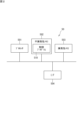
- FIG. 2 is a block diagram illustrating an example of a hardware configuration of the control device.
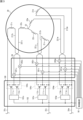
- FIG. 3 is a circuit diagram showing an example of the configuration of the winding switching device according to the first embodiment.
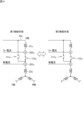
- FIG. 4 is a circuit diagram showing an example of the configuration of the current sensor and the windings according to the first embodiment.
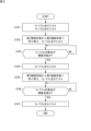
- FIG. 5 is a flowchart showing an example of a winding switching process performed by the control device according to the first embodiment.
- FIG. 6 is a timing chart showing an example of a winding switching process performed by the control device according to the first embodiment.
- FIG. 7 is a circuit diagram showing an example of the configuration of a winding switching device and a measurement unit in the second embodiment.
- FIG. 8 is a circuit diagram showing an example of the configuration of a modified example of a winding switching device.
- the winding switching system is a winding switching system for switching the connection state of a plurality of windings of a motor in which a stator of each phase includes a plurality of windings, and includes a first relay that is set to on when the connection state of the plurality of windings is a first connection state, a second relay that is set to off when the connection state of the plurality of windings is the first connection state, a first opening unit that sets the first relay to off when the connection state is switched from the first connection state to the second connection state, a first determination unit that determines whether the contact of the first relay set to off by the first opening unit is in an open state, and a first connection unit that sets the second relay to on when the first determination unit determines that the contact of the first relay is in an open state.
- the winding switching system may further include a second opening unit that sets the second relay to off when the connection state is switched from the second connection state to the first connection state, a second determination unit that determines whether the contact of the second relay set to off by the second opening unit is in an open state, and a second connection unit that sets the first relay to on when the second determination unit determines that the contact of the second relay is in an open state.
- the first determination unit may determine that the contact of the first relay is in an open state when a current measured by a current sensor that measures a current flowing through a switch including the contact of the first relay is equal to or less than a threshold value. This allows the current sensor to determine whether the relay is in an open state.
- the current sensor may be provided on a power line connecting the first relay and any of the windings of the motor. This allows the current sensor to be provided in various locations as long as it is provided on the power line connecting the first relay and the motor.
- the current sensor may be provided on a power line connecting the motor to a power supply circuit that supplies power to drive the motor. This allows the current sensor to be provided on the power line connecting the power supply circuit to the motor, and for example, a current sensor provided in the power supply circuit can be used.
- the first determination unit may determine whether the contact of the first relay is in an open state based on a voltage measured by a voltage sensor that measures the voltage across both ends of a switch including the contact of the first relay. In this way, the voltage sensor that measures the voltage across both ends of the switch of the relay can determine whether the relay is in an open state.
- the winding switching system may be configured such that the multiple windings include a first winding and a second winding, the first terminal of the first relay is connected to the second terminal of the first winding, the second terminal of the first relay is connected to the first terminal of the second winding, the first terminal of the second relay is connected to the first terminal of the second winding, and the second terminal of the second relay is connected to the first terminal of the first winding.
- the winding switching system may further include a third relay that is set to off when the connection state of the plurality of windings is the first connection state, a first terminal of the third relay is connected to the second terminal of the first winding, a second terminal of the third relay is connected to the second terminal of the second winding, and the first connection unit may set the third relay to on when switching the connection state from the first connection state to the second connection state. This makes it possible to prevent the relays from being simultaneously turned on even when the connection state of the windings is switched between the first connection state in which two windings are connected in series and the second connection state in which two windings are connected in parallel.
- the first opening unit may send an instruction to a power supply circuit that supplies power to drive the motor to suppress the power and set the first relay to off. This allows the relay to be set to off while the current flowing through the winding is suppressed, preventing the relay contacts from fusing and extending the life of the relay.
- the first connection unit may set the second relay on and send an instruction to the power supply circuit that supplies power to drive the motor to restore the suppressed power to the state before the suppression. This allows the power to drive the motor to be quickly restored to the original state after the winding switching system switches the connection state of the windings.
- the first opening unit when the first opening unit switches the connection state from the first connection state to the second connection state, the first opening unit may set the first relay to off upon receiving a notification indicating that the power for driving the motor has been reduced. This allows the relay to be set to off while the current flowing through the winding is reduced, thereby preventing the relay contacts from fusing and extending the life of the relay.
- the vehicle motor drive system includes an AC motor in which the stator of each phase includes multiple windings and drives the wheels of the vehicle, a power converter that converts DC power into three-phase AC power that drives the AC motor, and a winding switching system described in any one of (1) to (11) above that switches the connection state of the multiple windings. This makes it possible to prevent multiple relays from being turned on simultaneously, even in a vehicle equipped with a winding switching device that switches the connection state of the windings of the AC motor that drives the wheels of the vehicle.
- the control device is a control device that controls a winding switching device that switches the connection state of multiple windings of a motor in which a stator of each phase includes multiple windings, and includes an opening unit that sets off a first relay that is set on when the connection state of the multiple windings is a first connection state when switching from the first connection state to a second connection state, a determination unit that determines whether the contact of the first relay set off by the first opening unit is in an open state, and a connection unit that sets on a second relay that is set off when the connection state of the multiple windings is the first connection state when the determination unit determines that the contact of the first relay is in an open state. This makes it possible to avoid the relays being simultaneously on even when the connection state of multiple windings is switched by multiple relays.
- the winding switching method is a winding switching method for switching the connection state of a plurality of windings of a motor in which a stator of each phase includes a plurality of windings, and includes the steps of: setting off a first relay that is set on when the connection state of the plurality of windings is a first connection state, when switching from the first connection state to a second connection state; determining whether the contact of the first relay that is set off by the first opening unit is in an open state; and setting on a second relay that is set off when the connection state of the plurality of windings is the first connection state, when the determination unit determines that the contact of the first relay is in an open state.
- Winding switching system] 1 is a diagram showing an example of the configuration of a winding switching system according to a first embodiment.
- the winding switching system 10 is mounted on a vehicle (hereinafter referred to as an "electric vehicle") that is driven by a motor, such as an electric vehicle or a plug-in hybrid vehicle.
- the winding switching system 10 includes a motor 20, a power converter 30, a battery 40, a control device 50, and a winding switching device 100.
- Motor 20 is a driving motor that generates the propulsion force for the electric vehicle.
- motor 20 is connected to wheels 60 and is a drive motor that drives wheels 60.
- Motor 20 is driven by three-phase AC power.
- motor 20 is a non-commutator type AC motor that does not have a commutator, and drives a stator with three-phase AC power to generate a rotating magnetic field, which then rotates the rotor.
- Non-commutator type AC motors include, for example, synchronous motors, reluctance motors, and induction motors.
- the battery 40 is a battery that supplies power to drive the motor 20.
- the battery 40 is a secondary battery, for example a lithium ion battery.
- the power converter 30 includes legs for the U, V, and W phases.
- the U-phase leg includes switches 31u and 32u
- the V-phase leg includes switches 31v and 32v
- the W-phase leg includes switches 31w and 32w.
- the switches 31u, 32u, 31v, 32v, 31w, and 32w perform switching to convert DC power into three-phase AC power.
- the switches 31u, 32u, 31v, 32v, 31w, and 32w are, for example, IGBTs (Insulated Gate Bipolar Transistors) or MOSFETs (Metal Oxide Semiconductor Field-Effect Transistors).
- Power line 35u corresponding to U phase extends from the U phase leg
- power line 35v corresponding to V phase extends from the V phase leg
- power line 35w corresponding to W phase extends from the W phase leg.
- current sensor 33u is provided on power line 35u
- current sensor 33v is provided on power line 35v
- current sensor 33w is provided on power line 35w.
- Current sensor 33u measures the current value of current Iu of U phase.
- Current sensor 33v measures the current value of current Iv of V phase.
- Current sensor 33w measures the current value of current Iw of W phase.
- Current sensors 33u, 33v, 33w can measure the current values of currents Iu, Iv, Iw flowing through power lines 35u, 35v, 35w, including DC and AC components.
- the current sensors 33u, 33v, and 33w are, for example, DC current sensors using Hall sensors or shunt resistors.
- the winding switching device 100 is disposed between the motor 20 and the power converter 30.
- the power converter 30 and the winding switching device 100 are connected by power lines 35u, 35v, and 35w, and the winding switching device 100 and the motor 20 are connected by a plurality of power lines 25.
- the winding switching device 100 switches the connection state of the multiple windings of the motor 20. The configuration of the winding switching device 100 will be described later.
- the three-phase AC currents Iu, Iv, and Iw output from the power converter 30 are supplied to the motor 20 via the winding switching device 100.
- the measuring unit 26 measures a physical quantity related to the rotation of the motor 20.
- An example of a physical quantity related to the rotation of the motor is the current flowing through each winding of the motor 20, but is not limited to current.
- the measuring unit 26 is provided at a location corresponding to the measurement target. When measuring the current of the power line connecting the winding switching device 100 and the motor 20, the measuring unit 26 is provided on the power lines 212u, 221u, 212v, 221v, 212w, and 221w between the measuring unit 26 and the motor 20.
- the current is measured by a DC current sensor that uses, for example, a Hall sensor.
- the control device 50 controls the motor 20. Specifically, the control device 50 controls the motor 20 by controlling the power converter 30 and the winding switching device 100. Signal lines extend from the control device 50 to each of the switches 31u, 32u, 31v, 32v, 31w, and 32w, and the control device 50 controls the on and off of the switches 31u, 32u, 31v, 32v, 31w, and 32w. A signal line extends from the control device 50 to the winding switching device 100, and the control device 50 outputs a switching command signal to the winding switching device 100 to command the switching of the winding connection state.
- the control device 50 is connected to a sensor 71 that detects the amount of depression of the brake pedal 70, and receives a detection signal output from the sensor 71.
- the control device 50 is connected to a sensor 81 that detects the amount of depression of the accelerator pedal 80, and receives a detection signal output from the sensor 81.
- a rotation sensor 201 that detects the rotation speed of the motor 20 and a torque sensor 202 that detects the output torque of the motor 20 are attached to the output shaft of the motor 20.
- the rotation sensor 201 and the torque sensor 202 are connected to the control device 50.
- the control device 50 receives the detection signal output from the rotation sensor 201 and receives the detection signal output from the torque sensor 202.
- the control device 50 is connected to a gear shift indicator 90.
- the gear shift indicator 90 is an input device that allows the driver to input gear shift instructions.
- the gear shift indicator 90 is, for example, a shift lever.
- the gear shift indicator 90 is a switch that allows the driver to instruct shifting up or down.
- the gear shift indicator 90 outputs a gear shift instruction signal in response to the driver's operation.
- the control device 50 receives the gear shift instruction signal output from the gear shift indicator 90.
- the volatile memory 503 is, for example, a semiconductor memory such as SRAM (Static Random Access Memory) or DRAM (Dynamic Random Access Memory).
- the non-volatile memory 502 is, for example, a flash memory, a hard disk, or a ROM (Read Only Memory).
- the non-volatile memory 502 stores a control program 510, which is a computer program, and data used to execute the control program 510. Each function of the control device 50 is achieved by the processor 501 executing the control program 510.
- the control program 510 can be stored in a recording medium such as a flash memory, a ROM, or a CD-ROM.
- the processor 501 controls the power converter 30 and the winding switching device 100 using the control program 510.
- the processor 501 is, for example, a CPU (Central Processing Unit). However, the processor 501 is not limited to a CPU.
- the processor 501 may be a GPU (Graphics Processing Unit).
- the processor 501 is, for example, a multi-core processor.
- the processor 501 may be a single-core processor.
- the processor 501 may be, for example, an ASIC (Application Specific Integrated Circuit), or a programmable logic device such as a gate array or an FPGA (Field Programmable Gate Array). In this case, the ASIC or the programmable logic device is configured to be capable of executing the same processing as the control program 510.
- ASIC Application Specific Integrated Circuit
- FPGA Field Programmable Gate Array
- the I/F 504 is connected to the rotation sensor 201, the torque sensor 202, the sensor 71, the sensor 81, and the gear shift indicator 90.
- the I/F 504 is, for example, an input/output interface or a communication interface.
- the I/F 504 receives a detection signal of the rotation speed of the motor 20 output from the rotation sensor 201.
- the I/F 504 receives a detection signal of the output torque of the motor 20 output from the torque sensor 202.
- the I/F 504 receives a detection signal of the brake pedal depression amount output from the sensor 71.
- the I/F 504 receives a detection signal of the accelerator pedal depression amount output from the sensor 81.
- the I/F 504 receives a gear shift indicator signal output from the gear shift indicator 90.
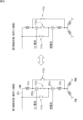
- FIG. 3 is a circuit diagram showing an example of the configuration of the winding switching device according to the first embodiment.
- the motor 20 includes a plurality of windings 21u, 22u, 21v, 22v, 21w, and 22w.
- the windings 21u and 22u correspond to the U phase
- the windings 21v and 22v correspond to the V phase
- the windings 21w and 22w correspond to the W phase.
- the number of windings for each phase is not limited to two, and may be three or more.
- the windings 22u, 22v, and 22w are connected at a neutral point 23.
- the winding switching device 100 switches the connection state of the windings 21u, 22u, 21v, 22v, 21w, and 22w for each phase between a first connection state and a second connection state.
- the winding switching device 100 includes control circuits 103u, 103v, and 103w and switching circuits 104u, 104v, and 104w.
- the switching circuits 104u, 104v, and 104w switch the connection state of the windings 21u, 22u, 21v, 22v, 21w, and 22w between a state in which two windings are connected in series and a state in which one winding is connected, according to the control from the control device 50.
- the state in which two windings are connected in series is a state in which, in the U phase, the first terminal of the winding 21u is connected to the power line 35u, the second terminal is connected to the first terminal of the winding 22u via the relay 112u, and the second terminal of the winding 22u is connected to the neutral point 23.
- the state in which one winding is connected is a state in which the first terminal of the winding 22u is connected to the power line 35u via the relay 111u, and the second terminal of the winding 22u is connected to the neutral point 23.
- the state in which two windings are connected in series is an example of the first connection state.
- the state in which one winding is connected is an example of the second connection state.
- winding 21u is the first winding
- winding 22u is the second winding.
- the power line 35u is connected to a first terminal of the winding 21u.
- the power line 212u extends from a second terminal of the winding 21u.
- the power line 221u extends from a first terminal of the winding 22u.
- the switching circuit 104u includes relays 111u and 112u.
- the relays 111u and 112u are, for example, mechanical (electromagnetic) relays, but are not limited to this and may be semiconductor relays.
- the relay is divided into an input side and an output side.
- the input side is composed of an electromagnetic coil
- the output side is composed of contacts.
- the input side is composed of a light-emitting diode
- the output side is composed of a light-receiving element, a MOSFET, and an IGBT.
- the power line 35u is drawn into the winding switching device 100. Inside the winding switching device 100, the power line 35u branches at a midpoint and is connected to a first terminal of a relay 111u. The second terminal of the relay 111u is connected to a first terminal of a relay 112u.
- the power lines 212u and 221u extend from the motor 20 and are drawn into the winding switching device 100.
- the power line 221u extending from the winding 22u is connected to the connection point between the second terminal of the relay 111u and the first terminal of the relay 112u.
- the power line 212u extending from the winding 21u is connected to the second terminal of the relay 112u.
- a communication line extending from the control circuit 103u is connected to each of the input sides (electromagnetic coil sides) of the relays 112u and 111u.
- a communication line 102 extending from the control device 50 is connected to the control circuit 103u.
- the control device 50 transmits a switching signal SS indicating which connection state of the windings should be set via the communication line 102. For example, when the switching signal SS is at a LOW level, it indicates a first connection state, and when it is at a HIGH level, it indicates a second connection state.
- the switching signal SS may be data including information indicating which relay is to be set on or off.
- the LOW level is, for example, the potential of the vehicle body
- the HIGH level is, for example, the potential of the power supply supplied to the control device 50.
- the control circuit 103u sets the relays 112u and 111u on or off by applying control signals individually to the input sides of the relays 112u and 111u. Specifically, when the control circuit 103u receives a switching signal SS from the control device 50 to switch the connection state of the windings 21u, 22u from the first connection state to the second connection state, the control circuit 103u sets the relay 111u to the on state and the relay 112u to the off state. When the control circuit 103u receives a switching signal SS from the control device 50 to switch the connection state of the windings 21u, 22u from the first connection state to the second connection state, the control circuit 103u sets the relay 111u to the off state and the relay 112u to the on state.
- the control circuit 103u is, for example, configured with multiple logic circuits (AND circuits, NOT circuits, latch circuits, etc.). In another example, the control circuit 103u is configured with a processor. For example, the control circuit 103u is configured with a one-chip microcomputer. The control circuit 103u may also be configured with a programmable logic device such as an ASIC or FPGA.
- the measurement unit 26 is provided on the power line connecting the winding switching device 100 and the motor 20.
- the measurement unit 26 includes a phase current sensor and a relay current sensor.
- the phase current sensor 261u is provided on the power line 221u
- the relay current sensor 262u is provided on the power line 212u.
- the phase current sensor 261u measures the current flowing through the U phase when the windings 21u and 22u are in the first connection state and the second connection state.
- the current measured by the phase current sensor may be referred to as the phase current.
- a signal or information indicating the value of the current measured by the phase current sensor 261u is sent to the control device 50.
- the relay current sensor 262u measures the current flowing through the power line 212u connected to the second terminal of the relay 112u.
- the relay current sensor 262u measures the current of the power line 212u that the relay 112u, which is set to off, is attempting to cut off.
- the current measured by the relay current sensor may be referred to as the relay current.
- a signal or information indicating the value of the current measured by the relay current sensor 262u is sent to the control device 50.
- a phase current sensor 261v is provided on the power line 221v, and a relay current sensor 262v is provided on the power line 212v.
- a phase current sensor 261w is provided on the power line 221w, and a relay current sensor 262w is provided on the power line 212w. Note that if the winding switching system 10 is configured without measuring the relay current, it is not necessary to provide a relay current sensor.
- the measurement unit 26 only needs to be provided on the power line connecting the winding switching device 100 and the motor 20, and the measurement unit 26 may be provided within the winding switching device 100 or within the motor 20.
- the control device 50 has the functions of a first opening unit 511, a first determination unit 512, a first connection unit 513, a second opening unit 514, a second determination unit 515, and a second connection unit 516.
- the processor 501 executes the control program 510 to realize the functions of the first opening unit 511, the first determination unit 512, the first connection unit 513, the second opening unit 514, the second determination unit 515, and the second connection unit 516.
- Only the U phase will be described, but the same is true for the V phase and the W phase. Below, an example will be described in which the connection state is switched from the first connection state to the second connection state, and then switched from the second connection state to the first connection state.
- the first opening unit sets the first relay to OFF when switching the connection state from the first connection state to the second connection state.
- the first relay is set to ON in the first connection state.
- the first relay is relay 112u and the second relay is relay 111u.
- the initial state is the first connection state, so relay 111u is set off and relay 112u is set on.
- the control device 50 transmits a switching signal SS to the control circuit 103u, which indicates that relay 111u is set off and relay 112u is set on.
- the control circuit 103u sets relay 111u of the switching circuit 104u off and sets relay 112u on.
- the first opening section 511 sets the first relay, relay 112u, to OFF.
- the control device 50 transmits, for example, a switching signal SS indicating that relay 112u is to be set to OFF to the control circuit 103u.
- the control circuit 103u that receives the switching signal SS sets the relay 112u of the switching circuit 104u to OFF.
- the first determination unit determines whether or not the contact of the first relay set to OFF by the first opening unit is in an open state.
- a mechanical relay is composed of an electromagnet and a switch.
- the relay is an A-contact relay
- the relay when the current flowing through the electromagnet of the relay is stopped, the relay is set to off.
- A-contact relays are also called normally-off relays.
- the electromagnet that acted as a magnet loses its magnetic function, and the movable segment of the switch of the relay that was attracted by the electromagnet is pulled away by the force of an elastic body such as a spring.
- the movable segment is pulled away, the first contact provided on the movable segment of the switch and the second contact provided on the fixed segment are pulled away.
- a diode may be connected in parallel to the relay's electromagnet. This is because the magnetic energy stored in the electromagnet's coil is circulated by the diode and absorbed as a current circulating through the electromagnet coil and diode. The current circulating through the electromagnet coil and diode gradually decays, but if this current is sufficient to attract the movable contact of the switch, the switch will become electrically conductive. This can sometimes result in the relay's reset time being unexpectedly long.
- the first determination unit 512 of the present disclosure therefore determines whether the contact of the first relay that has been set to off by the first opening unit is in an open state. Specifically, for example, the first determination unit 512 determines that the contact of the first relay is in an open state when the current measured by a current sensor that measures the current flowing through a switch including the contact of the first relay is equal to or less than a threshold value.
- Fig. 4 is a circuit diagram showing an example of the configuration of the current sensor and the winding according to the first embodiment.
- the current sensor that measures the current flowing through the switch including the contact of the first relay is a phase current sensor 261u.
- Fig. 4 shows only the U phase, but the V phase and the W phase are similar.
- the phase current sensor 261u is inserted in the power line 221u that connects the connection point where the second terminal of the relay 111u and the first terminal of the relay 112u are connected to the first terminal of the winding 22u.
- the phase current sensor 261u measures the current flowing through the power line 221u.
- the current flowing through the switch including the contact of the first relay set to off is measured.
- the relay set to on in the first connection state is relay 112u. Therefore, relay 112u corresponds to the first relay.
- the relay set to off in the first connection state is relay 111u. Therefore, relay 111u is the second relay.
- the first opening section 511 sets relay 112u, which is the first relay, from on to off.
- relay 111u is not set to on.
- phase current sensor 261u measures only the current flowing through the path of winding 21u, relay 112u, and winding 22u. Therefore, phase current sensor 261u can measure the current flowing through the switch including the contact of relay 112u.
- the phase current sensor 261u has been described as an example of a current sensor that measures the current flowing through a switch including the contacts of the first relay, but the present invention is not limited to a phase current sensor.
- the current sensor may be provided on a power line connecting the power supply circuit and the motor.
- the power converter 30 corresponds to the power supply circuit.
- the current sensor 33u corresponds to a current sensor that measures the current flowing through the first relay.
- the current sensor 33u is provided on a power line 35u that connects the power converter 30 and the motor 20.
- the current sensor may be provided in the power converter 30 or in the winding switching device 100.
- relay 112u corresponds to the first relay
- relay 111u corresponds to the second relay.
- the first opening section 511 sets relay 112u, which is the first relay, from on to off.
- relay 111u is not set to on.
- current sensor 33u measures the current flowing through power line 35u, and therefore measures only the current flowing through the path of winding 21u, relay 112u, and winding 21u. Therefore, current sensor 33u can measure the current flowing through the switch of relay 112u.
- the first determination unit 512 determines that the contact of the first relay is in an open state when the current measured by the current sensor is equal to or less than a threshold value.
- the threshold value may be set to a value close to zero, but may also be set to a value lower than the current that normally flows, taking noise, etc. into consideration.
- the first connection unit sets the second relay to ON when the first determination unit determines that the contact of the first relay is in an open state.
- the first opening section 511, the first judgment section 512, and the first connection section 513 are provided in the control device 50.
- the first opening section 511, the first judgment section 512, and the first connection section 513 may be provided in the control circuit 103u.
- the control circuit 103u is configured, for example, by a one-chip microcomputer.
- a one-chip microcomputer includes, for example, a processor, a non-volatile memory, a volatile memory, and the like.
- a control program is stored in the non-volatile memory.
- the processor of the one-chip microcomputer executes the control program to realize the functions of the first opening section 511, the first judgment section 512, and the first connection section 513.
- the phase current sensor 261u may send a signal indicating the measured current value or data including information to the control circuit 103u.
- the first opening unit 511 may also send an instruction to reduce power to the power supply circuit that supplies power to drive the motor, and set the first relay off.
- the control device 50 which receives the instruction to reduce power, controls the power converter 30 to turn off or reduce the power that drives the motor 20.
- the first connection unit may also set the second relay on and send an instruction to the power supply circuit that supplies power to drive the motor to restore the suppressed power to its pre-suppression state.
- the control device 50 upon receiving an instruction to restore the suppressed power to its pre-suppression state, controls the power converter 30 to return the current driving the motor 20 to its pre-suppression state. After the winding switching system switches the winding connection state, the motor 20 can quickly return to its original state.
- the first opening unit may set the first relay off upon receiving a notification indicating that the power driving the motor has been reduced.
- the control device 50 first controls the power converter 30 to turn off or reduce the power driving the motor 20.
- the control device 50 then sends a notification indicating that the power driving the motor has been reduced to the first opening unit 511.
- the first opening unit 511 which has received the notification indicating that the power has been reduced, sets the first relay off. This makes it possible to set the relay off when the current flowing through the winding is low, thereby preventing the risk of the relay contacts fusing and extending the life of the relay.
- the second opening unit sets the second relay to off when switching the connection state from the second connection state to the first connection state.
- the first relay is relay 112u
- the second relay is relay 111u. Therefore, when switching the connection state from the second connection state to the first connection state, the second opening unit 514 sets the second relay, relay 111u, to OFF.
- the control device 50 transmits, for example, a switching signal SS indicating that relay 111u is to be set to OFF to the control circuit 103u.
- the control circuit 103u which receives the switching signal SS, sets the relay 111u of the switching circuit 104u to OFF.
- the second determination unit determines whether or not the contact of the second relay that has been set to OFF by the second opening unit is in an open state. When a current measured by a current sensor that measures a current flowing through a switch including the contacts is equal to or less than a threshold value, it is determined that the contacts of the second relay are in an open state.
- the second determination unit 515 determines that the contacts of relay 111u, which is the second relay, are in an open state when the current measured by a current sensor that measures the current flowing through the switch of relay 111u is equal to or less than a threshold value.
- the second opening unit 514 sets the second relay, relay 111u, from on to off.
- relay 112u the first relay
- the phase current sensor 261u measures only the current flowing through the path of relay 111u and winding 22u. Therefore, the phase current sensor 261u can measure the current flowing through the switch of relay 112u.
- the second determination unit 515 determines whether the contact of the second relay is in an open state based on the current measured by the current sensor 33u.
- the phase current sensor 261u can measure the current flowing through the switches of the relays 111u and 112u. For this reason, the current sensor can be shared between the first judgment unit and the second judgment unit, but this is not limited to the above, and a current sensor may be provided in each of the first relay and the second relay.
- the second connection unit sets the first relay to ON when the second determination unit determines that the contact of the second relay is in an open state.
- the first relay is the relay 112u
- the second connection unit 516 sets the relay 112u to ON. More specifically, the second connection unit 516 transmits a switching signal SS representing the setting of the relay 112u to the control circuit 103u.
- the control circuit 103u receiving the switching signal SS sets the relay 112u to ON. This sets the connection state of the windings 21u, 22u to the first connection state.
- FIG. 5 is a flowchart showing an example of a winding switching process performed by the control device according to the first embodiment.
- FIG. 6 is a timing chart showing an example of a winding switching process performed by the control device according to the first embodiment. The following describes an example in which the control device 50 switches the winding connection state from the first connection state to the second connection state, and then switches from the second connection state to the first connection state.
- Step S101 In this example, since the initial state is the first connection state, the control device 50 transmits a switching signal SS indicating that the relay 111u is to be set to OFF and the relay 112u is to be set to ON to the control circuit 103u (step S101), and the process proceeds to step S102.
- the control circuit 103u having received the switching signal SS, sets the relay 111u to OFF and sets the relay 112u to ON. This state is indicated by the position of State 1 in the timing chart shown in FIG.
- Step S102 When switching the connection state from the first connection state to the second connection state, the first opening unit 511 sets the first relay to OFF (step S102).
- the first relay is the relay 112u.
- the first opening unit 511 sets the relay 112u, which is the first relay that is set to ON, to OFF.
- the control device 50 proceeds to step S102. This state is the position at which the state transitions from state 1 to state 2 in the timing chart shown in FIG. 6 .
- Step S103 The first determination unit determines whether or not the contact of the first relay that has been set to OFF by the first opening unit is in an open state (step S103).
- the first relay is relay 112u.
- the phase current sensor 261u or the current sensor 33u measures the current flowing through relay 112u.
- the first determination unit 512 determines that the contacts of the relay 112u are open (YES in step S103) and proceeds to step S104. On the other hand, if the current measured by the phase current sensor 261u or the current sensor 33u is equal to or greater than the threshold value, it determines that the contacts of the relay 112u are not open (NO in step S103) and returns to step S103, where the current is measured again by the phase current sensor 261u or the current sensor 33u, and the first determination unit 512 determines whether the measured current is equal to or less than the threshold value. This state is represented by state 2 in the timing chart shown in FIG. 6.
- the first connection unit sets the second relay to ON when the first determination unit determines that the contact of the first relay is in an open state (step S104).
- the first connection unit 513 transmits a switching signal SS to the control circuit 103u, which indicates that the second relay, relay 111u, is to be set to on.
- the control circuit 103u sets relay 111u to on. This sets the connection state of windings 21u, 22u to the second connection state. This state is the position at which the transition occurs from state 2 to state 3 in the timing chart shown in Figure 6. To subsequently switch the connection state from the second connection state to the first connection state, proceed to step S105.
- Step S105 When switching the connection state from the second connection state to the first connection state, the second opening unit 514 sets the second relay to OFF (step S105).
- the second relay is the relay 111u.
- the second opening unit 514 sets the relay 111u, which is set to ON, to OFF.
- the control device 50 proceeds to step S106. This state is the position at which the state transitions from state 3 to state 4 in the timing chart shown in FIG. 6 .
- Step S106 The second determination unit determines whether or not the contact of the second relay that has been set to OFF by the second opening unit is in an open state (step S106).
- the second determination unit 515 measures the current flowing through the contacts of the second relay that is set to off.
- the second relay is relay 111u.
- the current flowing through relay 111u is measured by phase current sensor 261u or current sensor 33u.
- the second judgment unit 515 judges that the contacts of the relay 111u are open (YES in step S106) and proceeds to step S107.
- the current measured by the phase current sensor 261u or the current sensor 33u is equal to or greater than the threshold value, it is judged that the contacts of the relay 111u are not open (NO in step S106) and the process returns to step S106, where the current is measured again by the phase current sensor 261u or the current sensor 33u, and the second judgment unit 515 judges whether the measured current is equal to or less than the threshold value.
- This state is represented by state 4 in the timing chart shown in FIG. 6.
- the second connection unit sets the first relay to ON when the second determination unit determines that the contact of the second relay is in an open state (step S107).
- the second connection unit 516 transmits a switching signal SS to the control circuit 103u, which indicates that the relay 112u is to be set on.
- the control circuit 103u receives the switching signal SS and sets the relay 112u on. This sets the connection state of the windings 21u, 22u to the first connection state. This state is the position at which the transition occurs from state 4 to state 5 in the timing chart shown in Figure 6. Then, after the relay 112u is set on, the winding switching process ends.
- the contacts of relays 111u and 112u are in an open state before the connection state of the windings is switched. This makes it possible to prevent the windings from being short-circuited even when multiple relays are used, and reduces the risk of large induced currents, torque fluctuations, and contact sticking due to large currents. For these reasons, the present disclosure is preferably applied to mechanical relays.
- the U, V, and W phases have been described as being independent, but the winding connection state may be changed for each phase simultaneously.
- the relay contacts are determined to be open when the values of the current sensors for the U, V, and W phases all reach zero and the connection state is switched, unevenness in each phase can be avoided.
- the circuits for all phases can be opened and closed simultaneously. This allows all phases to be operated uniformly by controlling one relay, simplifying the circuitry and making control easier.
- the winding switching device of the second embodiment includes a voltage sensor that measures the voltage across the switch including the setting of the first relay, and a determination unit determines whether or not the output switch is in an electrically open state based on the measured voltage.
- FIG. 7 is a circuit diagram showing an example of the configuration of the winding switching device and the measurement unit in the second embodiment.
- the second embodiment is different from the first embodiment in the configuration of the measurement unit 26, but the other configurations are the same. Descriptions of the same configurations as the first embodiment will be omitted, and only the different parts will be described, with the same reference numerals used for the same configurations.
- the measurement unit 26 includes voltage sensors 271u, 272u, 271v, 272v, 271w, and 272w.
- a voltage sensor 271u is connected between the U-phase power line 35u and the power line 221u, and the voltage sensor 271u measures the voltage across the switch of the relay 111u.
- a voltage sensor 272u is connected between the U-phase power line 221u and the power line 212u, and the voltage sensor 272u measures the voltage across the switch of the relay 112u.
- the voltage sensor sends information or a signal indicating the measured voltage to the control device 50. The same applies to the V-phase and W-phase.
- the second embodiment is different from the first embodiment in the functions of the first determination unit 512 and the second determination unit 515, but the other functions are the same. Also, the first determination unit 512 and the second determination unit 515 measure different relays, but the functions are the same.
- the first determination unit determines whether or not a contact of the first relay is in an open state based on a voltage measured by a voltage sensor that measures a voltage of the first relay.
- the first determination unit 512 measures the voltage across the output switch of the first relay, which is set to off.
- the relay that is set to on in the first connection state, which is the first connection state is relay 112u, and relay 112u corresponds to the first relay. Therefore, the voltage sensor 272u measures the voltage across the switch of relay 112u.
- the second determination unit 515 determines whether the contacts of the relay 111u are in an open state based on the voltage across the switch of the second relay, the relay 111u, measured by the voltage sensor 271u.
- the second embodiment differs from the first embodiment in the operations of steps S103 and S106, but the other operations are the same. Steps S103 and S106 measure different relays, but the operations are the same.
- Step S103 The first determination unit determines whether or not the contact of the first relay that has been set to OFF by the first opening unit is in an open state (step S103).
- the first determination unit 512 measures the voltage across the switch of the first relay that is set to off.
- the first relay is relay 112u.
- the voltage sensor 272u measures the voltage across the switch of relay 112u.
- step S103 If the voltage measured by the voltage sensor 272u is equal to or greater than the threshold, it is determined that the switch contacts are open (YES in step S103) and the process proceeds to step S103. On the other hand, if the voltage measured by the voltage sensor 272u is equal to or less than the threshold, it is determined that the switch contacts are not open (NO in step S103) and the process returns to step S103, where the first determination unit 512 again determines whether the voltage measured by the voltage sensor 272u is equal to or greater than the predetermined threshold.
- the voltage sensor can also be used to determine whether the relay contacts are open. Therefore, in the second embodiment, the winding connection state is switched after the switch contacts of relays 111u and 112u have both been in an open state. This prevents the windings from being short-circuited even when multiple relays are used, and reduces the risk of large induced currents, torque fluctuations, and contact sticking due to large currents.
- the vehicle motor drive system of the third embodiment includes an AC motor in which a stator of each phase includes multiple windings and drives the wheels of the vehicle, a power converter that converts DC power into three-phase AC power that drives the AC motor, and a winding switching system that switches the connection state of the multiple windings.
- the AC motor that drives the wheels of the vehicle is the traction motor 20 that generates the propulsion force for the electric vehicle.
- the motor 20 is connected to the wheels 60 and is a drive motor that drives the wheels 60.
- the motor 20 is driven by three-phase AC power.
- the stator of each phase of the motor 20 includes multiple windings. The characteristics of the motor 20 can be changed by switching between the multiple windings.
- the power converter 30 is an inverter that converts the DC power supplied from the battery 40 into three-phase AC power.
- the power converter 30 includes a leg for each phase.
- Each phase leg includes a switch. The switches perform switching to convert the DC power into three-phase AC power.
- the winding switching system 10 is a winding switching system that switches the connection state of a plurality of windings of a motor in which the stator of each phase includes a plurality of windings.
- the winding switching system 10 includes a first relay, a second relay, a first opening unit, a first determination unit, and a first connection unit.
- the first relay is set to on when the connection state of the plurality of windings is the first connection state.
- the second relay is set to off when the connection state of the plurality of windings is the first connection state.
- the first opening unit sets the first relay to off when the connection state is switched from the first connection state to the second connection state.
- the first determination unit determines whether the contact of the first relay set to off by the first opening unit is in an open state.
- the first connection unit sets the second relay to on when the first determination unit determines that the contact of the first relay is in an open state.
- the winding switching system 10 has such a configuration, and when the winding connection state is switched, all relays that switch the winding connection state are set to off before the connection state is switched. This prevents the windings from being short-circuited even when multiple relays are used, and reduces the risk of large induced currents, torque fluctuations, and contact sticking due to large currents. And even in a vehicle equipped with such a winding switching system 10, it is possible to prevent multiple relays from being turned on at the same time.
- the winding switching system may further include a third relay that is set to OFF when the connection state of the plurality of windings is the first connection state.
- a first terminal of the third relay is connected to the second terminal of the first winding, a second terminal of the third relay is connected to the second terminal of the second winding, and the first connection unit sets the third relay to ON when switching the connection state from the first connection state to the second connection state.
- the third relay is a relay 113u.
- connection states focusing on the second winding there are a first connection state in which the first winding is connected in series and a second connection state in which the first winding is not connected in series, and in the second connection state, the first winding may be connected in parallel.
- FIG. 8 is a circuit diagram showing an example of the configuration of a modified winding switching device 100.
- FIG. 8 shows only the U phase, the V phase and W phase are similar.
- a relay 113u has been added.
- the relay 113u is set to on or off at the same timing as the relay 111u.
- the addition of the relay 113u allows the windings 21u and 22u to be connected in parallel.
- the case of parallel connection may be referred to as the second connection state.
- the relays 111u and 113u are set to on, and the relay 112u is set to off.
- the relays 111u and 113u are set to off, and the relay 112u is set to on.
- the winding switching device 100 switches the connection state of the windings of the motor 20 from a first connection state to a second connection state, or from the second connection state to the first connection state. Even in this case, when the connection state of the windings is switched between the first connection state and the second connection state, all relays that switch the connection state of the windings are set to on or off after passing through a state in which they are set to off. This makes it possible to prevent the windings from becoming short-circuited even when multiple relays are used, and suppresses the risk of large induced currents, torque fluctuations, and contact sticking due to large currents.
- Winding switching system 20 Motor (drive motor) 21u, 22u, 21v, 22v, 21w, 22w Winding 23 Neutral point 25 Power line 26 Measurement unit 30 Power converter 31u, 32u, 31v, 32v, 31w, 32w Switch 33u, 33v, 33w Current sensor 35u, 35v, 35w Power line 40 Battery 50 Control device 501 Processor 502 Non-volatile memory 503 Volatile memory 504 Interface (I/F) 510 Control program 511 First opening section 512 First judgment section 513 First connection section 514 Second opening section 515 Second judgment section 516 Second connection section 60 Wheel 70 Brake pedal 71 Sensor 80 Accelerator pedal 81 Sensor 90 Gear shift indicator 100 Winding switching device 102 Communication line (switching signal SS) 102d Delay switching signal SS 103u, 103v, 103w Control circuit 104u, 104v, 104w Switching circuit 111u, 112u, 113u, 111v, 112v, 113v, 111w, 112w, 113
Landscapes
- Engineering & Computer Science (AREA)
- Power Engineering (AREA)
- Control Of Ac Motors In General (AREA)
Priority Applications (3)
| Application Number | Priority Date | Filing Date | Title |
|---|---|---|---|
| JP2024571652A JPWO2024154475A1 (cg-RX-API-DMAC7.html) | 2023-01-17 | 2023-12-08 | |
| CN202380090947.3A CN120569896A (zh) | 2023-01-17 | 2023-12-08 | 绕组切换系统、车辆电动机驱动系统、控制装置、绕组切换方法及计算机程序 |
| US19/148,658 US20260221920A1 (en) | 2023-01-17 | 2023-12-08 | Winding switching system, vehicle motor drive system, control device, winding switching method, and computer program |
Applications Claiming Priority (2)
| Application Number | Priority Date | Filing Date | Title |
|---|---|---|---|
| JP2023-005033 | 2023-01-17 | ||
| JP2023005033 | 2023-01-17 |
Publications (1)
| Publication Number | Publication Date |
|---|---|
| WO2024154475A1 true WO2024154475A1 (ja) | 2024-07-25 |
Family
ID=91955676
Family Applications (1)
| Application Number | Title | Priority Date | Filing Date |
|---|---|---|---|
| PCT/JP2023/044074 Ceased WO2024154475A1 (ja) | 2023-01-17 | 2023-12-08 | 巻線切替システム、車両モータ駆動システム、制御装置、巻線切替方法、及びコンピュータプログラム |
Country Status (4)
| Country | Link |
|---|---|
| US (1) | US20260221920A1 (cg-RX-API-DMAC7.html) |
| JP (1) | JPWO2024154475A1 (cg-RX-API-DMAC7.html) |
| CN (1) | CN120569896A (cg-RX-API-DMAC7.html) |
| WO (1) | WO2024154475A1 (cg-RX-API-DMAC7.html) |
Cited By (1)
| Publication number | Priority date | Publication date | Assignee | Title |
|---|---|---|---|---|
| WO2026155021A1 (ja) * | 2025-01-15 | 2026-07-23 | 株式会社オートネットワーク技術研究所 | 巻線切替装置 |
Citations (4)
| Publication number | Priority date | Publication date | Assignee | Title |
|---|---|---|---|---|
| JP2015211597A (ja) * | 2014-04-28 | 2015-11-24 | 日本電産株式会社 | 電動機駆動システム |
| JP2016167963A (ja) * | 2014-11-10 | 2016-09-15 | デンソートリム株式会社 | 内燃機関用回転電機 |
| JP2020114167A (ja) * | 2019-01-10 | 2020-07-27 | 株式会社デンソー | 制御装置及び回転電機システム |
| JP2020188597A (ja) * | 2019-05-15 | 2020-11-19 | 三菱重工サーマルシステムズ株式会社 | 巻線切替モータシステム、制御方法及びプログラム |
-
2023
- 2023-12-08 CN CN202380090947.3A patent/CN120569896A/zh active Pending
- 2023-12-08 JP JP2024571652A patent/JPWO2024154475A1/ja active Pending
- 2023-12-08 US US19/148,658 patent/US20260221920A1/en active Pending
- 2023-12-08 WO PCT/JP2023/044074 patent/WO2024154475A1/ja not_active Ceased
Patent Citations (4)
| Publication number | Priority date | Publication date | Assignee | Title |
|---|---|---|---|---|
| JP2015211597A (ja) * | 2014-04-28 | 2015-11-24 | 日本電産株式会社 | 電動機駆動システム |
| JP2016167963A (ja) * | 2014-11-10 | 2016-09-15 | デンソートリム株式会社 | 内燃機関用回転電機 |
| JP2020114167A (ja) * | 2019-01-10 | 2020-07-27 | 株式会社デンソー | 制御装置及び回転電機システム |
| JP2020188597A (ja) * | 2019-05-15 | 2020-11-19 | 三菱重工サーマルシステムズ株式会社 | 巻線切替モータシステム、制御方法及びプログラム |
Cited By (1)
| Publication number | Priority date | Publication date | Assignee | Title |
|---|---|---|---|---|
| WO2026155021A1 (ja) * | 2025-01-15 | 2026-07-23 | 株式会社オートネットワーク技術研究所 | 巻線切替装置 |
Also Published As
| Publication number | Publication date |
|---|---|
| JPWO2024154475A1 (cg-RX-API-DMAC7.html) | 2024-07-25 |
| US20260221920A1 (en) | 2026-07-30 |
| CN120569896A (zh) | 2025-08-29 |
Similar Documents
| Publication | Publication Date | Title |
|---|---|---|
| CN110460254B (zh) | 用于电力转换器的控制电路 | |
| CN105553210B (zh) | 无刷电机和电机控制设备 | |
| CN101133546B (zh) | 用于驱动电路的故障判断设备和包括故障判断设备的驱动单元以及用于判断驱动电路故障的方法 | |
| KR102232178B1 (ko) | 차량의 구동장치, 및 차량의 제어 방법 | |
| JP2019134590A (ja) | インバータ制御装置 | |
| US20150015178A1 (en) | Method and apparatus for monitoring and controlling a synchronous electric machine | |
| JP7479272B2 (ja) | 電力変換装置 | |
| JP7631751B2 (ja) | 電力変換装置及び電力変換システム | |
| CN120569896A (zh) | 绕组切换系统、车辆电动机驱动系统、控制装置、绕组切换方法及计算机程序 | |
| JP7530756B2 (ja) | 電力変換装置及び電力変換制御装置 | |
| WO2024154474A1 (ja) | 巻線切替システム、車両モータ駆動システム、制御装置、制御方法、及びコンピュータプログラム | |
| JP7559520B2 (ja) | 電力変換装置 | |
| JP2013219868A (ja) | 回転機の制御装置 | |
| JP2008099394A (ja) | モータ制御装置および電動パワーステアリング装置 | |
| CN106953556A (zh) | 无感测器三相马达驱动系统及其方法 | |
| Nitabaru et al. | Drive control development of switched reluctance motor for compact electric vehicles | |
| JP4943719B2 (ja) | スイッチトリラクタンスモータの回生制御装置 | |
| JP2022161346A (ja) | モータおよび車両用ドアシステム | |
| JP5017529B2 (ja) | 磁石式同期モータ用電力変換装置 | |
| WO2026034149A1 (ja) | モータ制御装置 | |
| WO2024154439A1 (ja) | 巻線切替装置、巻線切替システム及び巻線切替方法 | |
| JP7655122B2 (ja) | モータ制御装置、プログラム及びモータ制御方法 | |
| JP7499626B2 (ja) | 電力変換制御装置 | |
| JP7676998B2 (ja) | 車両用制御装置、及びプログラム | |
| JP7109631B1 (ja) | 電力変換装置 |
Legal Events
| Date | Code | Title | Description |
|---|---|---|---|
| 121 | Ep: the epo has been informed by wipo that ep was designated in this application |
Ref document number: 23917686 Country of ref document: EP Kind code of ref document: A1 |
|
| ENP | Entry into the national phase |
Ref document number: 2024571652 Country of ref document: JP Kind code of ref document: A |
|
| WWE | Wipo information: entry into national phase |
Ref document number: 2024571652 Country of ref document: JP |
|
| WWE | Wipo information: entry into national phase |
Ref document number: 202380090947.3 Country of ref document: CN |
|
| NENP | Non-entry into the national phase |
Ref country code: DE |
|
| WWP | Wipo information: published in national office |
Ref document number: 202380090947.3 Country of ref document: CN |
|
| 122 | Ep: pct application non-entry in european phase |
Ref document number: 23917686 Country of ref document: EP Kind code of ref document: A1 |